EP3396265A1 - Moyens d'ajustement et de blocage pour une plaque d'amortissement d'un dispositif de ventilation - Google Patents
Moyens d'ajustement et de blocage pour une plaque d'amortissement d'un dispositif de ventilation Download PDFInfo
- Publication number
- EP3396265A1 EP3396265A1 EP18162567.4A EP18162567A EP3396265A1 EP 3396265 A1 EP3396265 A1 EP 3396265A1 EP 18162567 A EP18162567 A EP 18162567A EP 3396265 A1 EP3396265 A1 EP 3396265A1
- Authority
- EP
- European Patent Office
- Prior art keywords
- adjustment
- locking means
- damper plate
- regulator slide
- handle part
- Prior art date
- Legal status (The legal status is an assumption and is not a legal conclusion. Google has not performed a legal analysis and makes no representation as to the accuracy of the status listed.)
- Granted
Links
Images
Classifications
-
- F—MECHANICAL ENGINEERING; LIGHTING; HEATING; WEAPONS; BLASTING
- F24—HEATING; RANGES; VENTILATING
- F24F—AIR-CONDITIONING; AIR-HUMIDIFICATION; VENTILATION; USE OF AIR CURRENTS FOR SCREENING
- F24F11/00—Control or safety arrangements
- F24F11/89—Arrangement or mounting of control or safety devices
-
- F—MECHANICAL ENGINEERING; LIGHTING; HEATING; WEAPONS; BLASTING
- F24—HEATING; RANGES; VENTILATING
- F24F—AIR-CONDITIONING; AIR-HUMIDIFICATION; VENTILATION; USE OF AIR CURRENTS FOR SCREENING
- F24F13/00—Details common to, or for air-conditioning, air-humidification, ventilation or use of air currents for screening
- F24F13/08—Air-flow control members, e.g. louvres, grilles, flaps or guide plates
- F24F13/10—Air-flow control members, e.g. louvres, grilles, flaps or guide plates movable, e.g. dampers
-
- F—MECHANICAL ENGINEERING; LIGHTING; HEATING; WEAPONS; BLASTING
- F24—HEATING; RANGES; VENTILATING
- F24F—AIR-CONDITIONING; AIR-HUMIDIFICATION; VENTILATION; USE OF AIR CURRENTS FOR SCREENING
- F24F13/00—Details common to, or for air-conditioning, air-humidification, ventilation or use of air currents for screening
- F24F13/08—Air-flow control members, e.g. louvres, grilles, flaps or guide plates
- F24F13/10—Air-flow control members, e.g. louvres, grilles, flaps or guide plates movable, e.g. dampers
- F24F13/14—Air-flow control members, e.g. louvres, grilles, flaps or guide plates movable, e.g. dampers built up of tilting members, e.g. louvre
- F24F13/1426—Air-flow control members, e.g. louvres, grilles, flaps or guide plates movable, e.g. dampers built up of tilting members, e.g. louvre characterised by actuating means
- F24F2013/1453—Air-flow control members, e.g. louvres, grilles, flaps or guide plates movable, e.g. dampers built up of tilting members, e.g. louvre characterised by actuating means with cables, e.g. bowden cables
Definitions
- the object of this invention is an adjustment and locking means for a damper plate of a ventilation device, by the aid of which means the damper plate, or the like, of the ventilation device is adjusted, which damper plate is connected by the aid of a cable, wire, or the like, to the regulator slide of the adjustment and locking means.
- the invention thus relates to a device for ventilation, e.g. to a regulating box, which comprises a damper plate, or the like, for the purpose of adjusting the air flow.
- a damper plate is typically situated inside a regulating box near the inlet duct, so that access to it is difficult.
- Various adjustment mechanisms have been developed for this purpose. For example, a wire is fixed to the damper plate, to the other end of which wire an adjustment and locking means is installed, which in turn can be disposed in a location to which it is easy to gain access.
- the damper plate is moved in the longitudinal direction of the inlet duct by the aid of the adjustment and locking means, in which case in the minimum flow position the damper plate, which can also be a perforated plate, covers the duct.
- the damper plate is adjusted, by the aid of the adjustment and locking means, inwards in the regulating box farther away from the inlet duct.
- Finnish patent specification 124864 discloses an adjustment and locking means having threads on the outer surface of its body, onto which threads the protrusion or protrusions on the inside surface of the setting means is screwable, and a part of the thread extends to only a part of the outer rim of the body of the adjustment and locking means. In this way an adjustment can be made in the critical adjustment area extremely accurately, while in the other areas the adjustment can be made and locked quickly.
- the adjustment and locking means disclosed by the patent in question is functional, but it is rather large in size, more particularly in diameter.
- the large size hampers on-site adjustment of the device because it is not possible to thread it through the nozzle diffuser fastened to the regulating box for the adjustment phase.
- the aim of the present invention is to provide an adjustment and locking means for a ventilation device, the means having such a small diameter that it fits through a nozzle diffuser, in which case adjustment of the product on worksites and/or at installation points is easier in the adjustment phase. It is not then necessary to perform many extra opening and closing phases of the front plate.
- Another aim is to provide an adjustment and locking means with which the adjusting movement is sufficiently accurate in all adjustment positions.
- the adjustment and locking means according to the invention is characterized in that the adjustment and locking means comprises two parts, a handle part and a regulator slide, which regulator slide is installed inside the handle part.
- One preferred embodiment of the adjustment and locking means according to the invention is characterized in that threads are arranged on the outer rim of the regulator slide, of which the first thread is unbroken and the second thread extends to a part of the outer rim of the regulator slide.
- Another preferred embodiment of the adjustment and locking means according to the invention is characterized in that on the inside surface of the handle part are protrusions, which are able to move in the threads of the regulator slide.
- Yet another preferred embodiment of the invention is characterized in that the protrusions in the threadless area of the second thread part are able to move in the longitudinal direction of the regulator slide, in which case the adjustment can be made by pushing or pulling the regulator slide in relation to the handle part and the adjustment can be locked by rotating the regulator slide in relation to the handle part.
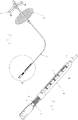
- Fig. 1 presents the adjustment and locking means according to the invention, which means is presented in Fig. 2 in more detail.
- a cable or wire which is mostly inside the shell 4 and is movable in its longitudinal direction, is fastened to the adjustment and locking means.
- the shell does not move, but instead is fixed in its position.
- the wire therefore, is able to move inside the shell.
- a damper plate 3 is fastened to the second end of the wire, which damper plate is thus moved by the aid of the adjustment and locking means.
- the drawings do not present the regulating box, inside which the damper plate in question is typically installed. When the damper plate is in the closing position, it essentially covers/closes the inlet duct entering the regulating box.
- the adjustment and locking means is used in the manner described later, it moves the wire in such a way that the damper plate 3 displaces in the direction of the wire.
- the reference number 5 presents the measuring device of air flow, which is per se conventional and does not itself relate to the invention. For this reason, its operation is not described in more detail here.
- Fig. 2 presents an adjustment and locking means according to the invention.
- the regulator slide which is installed inside the handle part 2, is marked with the reference number 1.
- On the handle part is an adjustment scale 6, by means of which the position of the damper plate is determined.
- On the regulator slide correspondingly, is an indicator, which is set to the desired point on the adjustment scale. The adjustment therefore takes place by moving the regulator slide in relation to the handle part.
- the aforementioned wire is fastened explicitly to the regulator slide 1.
- the outer rim of the regulator slide is provided with threads 7, 8.
- the thread 7 is unbroken and its length on the outer rim of the body corresponds to the length of the more accurate adjustment value 0-1 display of the adjustment scale 6.
- the thread 8 extends to only a part of the outer rim of the regulator slide 6.
- On the inner surface of the handle part 2 is/are a protrusion or protrusions, or the like, (not presented in the figures), which correspond to the threads 7, 8 of the outer rim of the regulator slide in such a way that the regulator slide 1 and handle part 2 can be rotated in relation to each other.
- the protrusion or protrusions is/are at the point of the regulator slide, where there are no threads, the parts move in relation to each other by pushing and by pulling.
- the adjustment can therefore be made extremely accurately (adjustment positions 0-1) by turning the regulator slide to the desired point. After that (adjustment positions 1-5) the adjustment can be done notch by notch, when the adjustment value changes by at least the amount of the pitch of the thread. A more precise adjustment value is therefore obtained near the closing position of the damper plate, where the relative change in air flow is more pronounced. In other words, just a very small adjustment movement substantially affects the air flow.
- the area of unbroken thread is e.g. approx. 10-20% of the whole adjustment area.
- the damper plate 3 can be closed, i.e. adjusted to the 0 position by rotating the regulator slide 1 clockwise and, correspondingly, can be opened from this position by rotating the regulator slide 1 counterclockwise.
- the damper plate can be opened by pulling the regulator slide 1 outwards from the handle part 2 and, correspondingly, can be closed by pushing the regulator slide inside the handle part.
- the adjustment is locked in adjustment positions 1-5 by rotating the regulator slide 90° clockwise.
- the locking is opened by rotating the regulator slide 90° counterclockwise.
- the invention is described above in connection with a regulating box. It is obvious that also other ventilation devices in which the air flow is adjusted fall into its scope. The invention can also be applied to a turning check plate.
Landscapes
- Engineering & Computer Science (AREA)
- Chemical & Material Sciences (AREA)
- Combustion & Propulsion (AREA)
- Mechanical Engineering (AREA)
- General Engineering & Computer Science (AREA)
- Air-Flow Control Members (AREA)
Applications Claiming Priority (1)
| Application Number | Priority Date | Filing Date | Title |
|---|---|---|---|
| FI20175366A FI129426B (fi) | 2017-04-24 | 2017-04-24 | Ilmanvaihtolaitteen säätölevyn säätö- ja lukituselin |
Publications (3)
| Publication Number | Publication Date |
|---|---|
| EP3396265A1 true EP3396265A1 (fr) | 2018-10-31 |
| EP3396265C0 EP3396265C0 (fr) | 2023-06-07 |
| EP3396265B1 EP3396265B1 (fr) | 2023-06-07 |
Family
ID=61691776
Family Applications (1)
| Application Number | Title | Priority Date | Filing Date |
|---|---|---|---|
| EP18162567.4A Active EP3396265B1 (fr) | 2017-04-24 | 2018-03-19 | Moyens d'ajustement et de blocage pour une plaque d'amortissement d'un dispositif de ventilation |
Country Status (2)
| Country | Link |
|---|---|
| EP (1) | EP3396265B1 (fr) |
| FI (1) | FI129426B (fr) |
Citations (4)
| Publication number | Priority date | Publication date | Assignee | Title |
|---|---|---|---|---|
| GB692041A (en) * | 1950-07-04 | 1953-05-27 | Arthur Henry Eakins | Improvements relating to quick-acting screw fastening devices |
| US5156064A (en) * | 1991-05-21 | 1992-10-20 | Handy & Harman Automotive Group, Inc. | Cable length adjustment device |
| JPH10197044A (ja) * | 1996-12-27 | 1998-07-31 | Kurimoto Ltd | 風量調整装置 |
| WO2012101317A1 (fr) * | 2011-01-25 | 2012-08-02 | Fläkt Woods AB | Moyen d'ajustement et de verrouillage pour une plaque d'amortissement d'un dispositif de ventilation |
-
2017
- 2017-04-24 FI FI20175366A patent/FI129426B/fi active IP Right Grant
-
2018
- 2018-03-19 EP EP18162567.4A patent/EP3396265B1/fr active Active
Patent Citations (4)
| Publication number | Priority date | Publication date | Assignee | Title |
|---|---|---|---|---|
| GB692041A (en) * | 1950-07-04 | 1953-05-27 | Arthur Henry Eakins | Improvements relating to quick-acting screw fastening devices |
| US5156064A (en) * | 1991-05-21 | 1992-10-20 | Handy & Harman Automotive Group, Inc. | Cable length adjustment device |
| JPH10197044A (ja) * | 1996-12-27 | 1998-07-31 | Kurimoto Ltd | 風量調整装置 |
| WO2012101317A1 (fr) * | 2011-01-25 | 2012-08-02 | Fläkt Woods AB | Moyen d'ajustement et de verrouillage pour une plaque d'amortissement d'un dispositif de ventilation |
Also Published As
| Publication number | Publication date |
|---|---|
| EP3396265C0 (fr) | 2023-06-07 |
| EP3396265B1 (fr) | 2023-06-07 |
| FI20175366A1 (fi) | 2018-10-25 |
| FI129426B (fi) | 2022-02-15 |
Similar Documents
| Publication | Publication Date | Title |
|---|---|---|
| RU2509193C2 (ru) | Замок для летательного аппарата, содержащий крюк и ручку | |
| US3724503A (en) | Flow measurement and control | |
| US3068891A (en) | Flow regulator for air control | |
| US9273787B2 (en) | Control valve | |
| EP3040589A1 (fr) | Réglage du débit d'air | |
| EP2806196B1 (fr) | Appareil de régulation d'écoulement | |
| EP3091301A1 (fr) | Agencement pour la regulation du debit d'un canal d'air dans lequel un debit d'air est genere par des appareils de ventilation ou similaire | |
| EP3396265A1 (fr) | Moyens d'ajustement et de blocage pour une plaque d'amortissement d'un dispositif de ventilation | |
| US6575046B1 (en) | Air mass flow measuring device and method of use | |
| EP2668449B1 (fr) | Moyen d'ajustement et de verrouillage pour une plaque d'amortissement d'un dispositif de ventilation | |
| NL2021027B1 (en) | Cover and base for an air diffuser, air diffuser, air diffusing system and method for controlling the air flow of an air diffusing system. | |
| DK174164B1 (da) | Spjældmekanisme til at regulere luftstrømmen fra en køkkenventilator | |
| DE69929650T2 (de) | Druckregler | |
| US3342212A (en) | Volume temperature control device for air outlet devices | |
| SK7733Y1 (sk) | Nastaviteľný regulátor prietoku tekutín, najmä vzduchu vo vzduchotechnických prvkoch | |
| SK90595A3 (en) | Woltmann's flow meter | |
| RU2374543C1 (ru) | Клапан избыточного давления | |
| US5665923A (en) | Full range-high accuracy air flow sensing device | |
| US1277413A (en) | Valve. | |
| TWI582324B (zh) | 流量調節裝置 | |
| WO2005088204A1 (fr) | Amortisseur d'air d'extraction | |
| EP2530396B1 (fr) | Valve de régulation de débit d'air | |
| DE19946797C1 (de) | Heizkörperthermostatventilaufsatz | |
| KR101052601B1 (ko) | 공기의 흐름량을 조절할 수 있는 분기덕트 | |
| WO2024038042A1 (fr) | Dispositif de réglage d'un débit volumétrique d'air |
Legal Events
| Date | Code | Title | Description |
|---|---|---|---|
| PUAI | Public reference made under article 153(3) epc to a published international application that has entered the european phase |
Free format text: ORIGINAL CODE: 0009012 |
|
| STAA | Information on the status of an ep patent application or granted ep patent |
Free format text: STATUS: THE APPLICATION HAS BEEN PUBLISHED |
|
| AK | Designated contracting states |
Kind code of ref document: A1 Designated state(s): AL AT BE BG CH CY CZ DE DK EE ES FI FR GB GR HR HU IE IS IT LI LT LU LV MC MK MT NL NO PL PT RO RS SE SI SK SM TR |
|
| AX | Request for extension of the european patent |
Extension state: BA ME |
|
| STAA | Information on the status of an ep patent application or granted ep patent |
Free format text: STATUS: REQUEST FOR EXAMINATION WAS MADE |
|
| 17P | Request for examination filed |
Effective date: 20190322 |
|
| RBV | Designated contracting states (corrected) |
Designated state(s): AL AT BE BG CH CY CZ DE DK EE ES FI FR GB GR HR HU IE IS IT LI LT LU LV MC MK MT NL NO PL PT RO RS SE SI SK SM TR |
|
| STAA | Information on the status of an ep patent application or granted ep patent |
Free format text: STATUS: EXAMINATION IS IN PROGRESS |
|
| 17Q | First examination report despatched |
Effective date: 20191014 |
|
| GRAP | Despatch of communication of intention to grant a patent |
Free format text: ORIGINAL CODE: EPIDOSNIGR1 |
|
| STAA | Information on the status of an ep patent application or granted ep patent |
Free format text: STATUS: GRANT OF PATENT IS INTENDED |
|
| RIC1 | Information provided on ipc code assigned before grant |
Ipc: F24F 13/14 20060101ALN20221011BHEP Ipc: F16K 31/50 20060101ALI20221011BHEP Ipc: F24F 13/10 20060101AFI20221011BHEP |
|
| RIC1 | Information provided on ipc code assigned before grant |
Ipc: F24F 13/14 20060101ALN20221017BHEP Ipc: F16K 31/50 20060101ALI20221017BHEP Ipc: F24F 13/10 20060101AFI20221017BHEP |
|
| INTG | Intention to grant announced |
Effective date: 20221111 |
|
| GRAS | Grant fee paid |
Free format text: ORIGINAL CODE: EPIDOSNIGR3 |
|
| RIN1 | Information on inventor provided before grant (corrected) |
Inventor name: SAARI, VESA |
|
| GRAA | (expected) grant |
Free format text: ORIGINAL CODE: 0009210 |
|
| STAA | Information on the status of an ep patent application or granted ep patent |
Free format text: STATUS: THE PATENT HAS BEEN GRANTED |
|
| AK | Designated contracting states |
Kind code of ref document: B1 Designated state(s): AL AT BE BG CH CY CZ DE DK EE ES FI FR GB GR HR HU IE IS IT LI LT LU LV MC MK MT NL NO PL PT RO RS SE SI SK SM TR |
|
| REG | Reference to a national code |
Ref country code: GB Ref legal event code: FG4D |
|
| REG | Reference to a national code |
Ref country code: CH Ref legal event code: EP Ref country code: AT Ref legal event code: REF Ref document number: 1576182 Country of ref document: AT Kind code of ref document: T Effective date: 20230615 |
|
| REG | Reference to a national code |
Ref country code: DE Ref legal event code: R096 Ref document number: 602018050672 Country of ref document: DE |
|
| U01 | Request for unitary effect filed |
Effective date: 20230607 |
|
| U07 | Unitary effect registered |
Designated state(s): AT BE BG DE DK EE FI FR IT LT LU LV MT NL PT SE SI Effective date: 20230612 |
|
| REG | Reference to a national code |
Ref country code: NO Ref legal event code: T2 Effective date: 20230607 |
|
| REG | Reference to a national code |
Ref country code: LT Ref legal event code: MG9D |
|
| PG25 | Lapsed in a contracting state [announced via postgrant information from national office to epo] |
Ref country code: ES Free format text: LAPSE BECAUSE OF FAILURE TO SUBMIT A TRANSLATION OF THE DESCRIPTION OR TO PAY THE FEE WITHIN THE PRESCRIBED TIME-LIMIT Effective date: 20230607 |
|
| PG25 | Lapsed in a contracting state [announced via postgrant information from national office to epo] |
Ref country code: RS Free format text: LAPSE BECAUSE OF FAILURE TO SUBMIT A TRANSLATION OF THE DESCRIPTION OR TO PAY THE FEE WITHIN THE PRESCRIBED TIME-LIMIT Effective date: 20230607 Ref country code: HR Free format text: LAPSE BECAUSE OF FAILURE TO SUBMIT A TRANSLATION OF THE DESCRIPTION OR TO PAY THE FEE WITHIN THE PRESCRIBED TIME-LIMIT Effective date: 20230607 Ref country code: GR Free format text: LAPSE BECAUSE OF FAILURE TO SUBMIT A TRANSLATION OF THE DESCRIPTION OR TO PAY THE FEE WITHIN THE PRESCRIBED TIME-LIMIT Effective date: 20230908 |
|
| PG25 | Lapsed in a contracting state [announced via postgrant information from national office to epo] |
Ref country code: SK Free format text: LAPSE BECAUSE OF FAILURE TO SUBMIT A TRANSLATION OF THE DESCRIPTION OR TO PAY THE FEE WITHIN THE PRESCRIBED TIME-LIMIT Effective date: 20230607 |
|
| PG25 | Lapsed in a contracting state [announced via postgrant information from national office to epo] |
Ref country code: IS Free format text: LAPSE BECAUSE OF FAILURE TO SUBMIT A TRANSLATION OF THE DESCRIPTION OR TO PAY THE FEE WITHIN THE PRESCRIBED TIME-LIMIT Effective date: 20231007 |
|
| PG25 | Lapsed in a contracting state [announced via postgrant information from national office to epo] |
Ref country code: SM Free format text: LAPSE BECAUSE OF FAILURE TO SUBMIT A TRANSLATION OF THE DESCRIPTION OR TO PAY THE FEE WITHIN THE PRESCRIBED TIME-LIMIT Effective date: 20230607 Ref country code: SK Free format text: LAPSE BECAUSE OF FAILURE TO SUBMIT A TRANSLATION OF THE DESCRIPTION OR TO PAY THE FEE WITHIN THE PRESCRIBED TIME-LIMIT Effective date: 20230607 Ref country code: RO Free format text: LAPSE BECAUSE OF FAILURE TO SUBMIT A TRANSLATION OF THE DESCRIPTION OR TO PAY THE FEE WITHIN THE PRESCRIBED TIME-LIMIT Effective date: 20230607 Ref country code: IS Free format text: LAPSE BECAUSE OF FAILURE TO SUBMIT A TRANSLATION OF THE DESCRIPTION OR TO PAY THE FEE WITHIN THE PRESCRIBED TIME-LIMIT Effective date: 20231007 Ref country code: CZ Free format text: LAPSE BECAUSE OF FAILURE TO SUBMIT A TRANSLATION OF THE DESCRIPTION OR TO PAY THE FEE WITHIN THE PRESCRIBED TIME-LIMIT Effective date: 20230607 |
|
| PG25 | Lapsed in a contracting state [announced via postgrant information from national office to epo] |
Ref country code: PL Free format text: LAPSE BECAUSE OF FAILURE TO SUBMIT A TRANSLATION OF THE DESCRIPTION OR TO PAY THE FEE WITHIN THE PRESCRIBED TIME-LIMIT Effective date: 20230607 |
|
| REG | Reference to a national code |
Ref country code: DE Ref legal event code: R097 Ref document number: 602018050672 Country of ref document: DE |
|
| PLBE | No opposition filed within time limit |
Free format text: ORIGINAL CODE: 0009261 |
|
| STAA | Information on the status of an ep patent application or granted ep patent |
Free format text: STATUS: NO OPPOSITION FILED WITHIN TIME LIMIT |
|
| U20 | Renewal fee for the european patent with unitary effect paid |
Year of fee payment: 7 Effective date: 20240311 |
|
| 26N | No opposition filed |
Effective date: 20240308 |
|
| REG | Reference to a national code |
Ref country code: CH Ref legal event code: PL |
|
| PG25 | Lapsed in a contracting state [announced via postgrant information from national office to epo] |
Ref country code: MC Free format text: LAPSE BECAUSE OF FAILURE TO SUBMIT A TRANSLATION OF THE DESCRIPTION OR TO PAY THE FEE WITHIN THE PRESCRIBED TIME-LIMIT Effective date: 20230607 |
|
| GBPC | Gb: european patent ceased through non-payment of renewal fee |
Effective date: 20240319 |
|
| PG25 | Lapsed in a contracting state [announced via postgrant information from national office to epo] |
Ref country code: MC Free format text: LAPSE BECAUSE OF FAILURE TO SUBMIT A TRANSLATION OF THE DESCRIPTION OR TO PAY THE FEE WITHIN THE PRESCRIBED TIME-LIMIT Effective date: 20230607 |
|
| PG25 | Lapsed in a contracting state [announced via postgrant information from national office to epo] |
Ref country code: GB Free format text: LAPSE BECAUSE OF NON-PAYMENT OF DUE FEES Effective date: 20240319 |
|
| PG25 | Lapsed in a contracting state [announced via postgrant information from national office to epo] |
Ref country code: IE Free format text: LAPSE BECAUSE OF NON-PAYMENT OF DUE FEES Effective date: 20240319 |
|
| PG25 | Lapsed in a contracting state [announced via postgrant information from national office to epo] |
Ref country code: IE Free format text: LAPSE BECAUSE OF NON-PAYMENT OF DUE FEES Effective date: 20240319 Ref country code: GB Free format text: LAPSE BECAUSE OF NON-PAYMENT OF DUE FEES Effective date: 20240319 Ref country code: CH Free format text: LAPSE BECAUSE OF NON-PAYMENT OF DUE FEES Effective date: 20240331 |
|
| U20 | Renewal fee for the european patent with unitary effect paid |
Year of fee payment: 8 Effective date: 20250317 |
|
| PG25 | Lapsed in a contracting state [announced via postgrant information from national office to epo] |
Ref country code: CY Free format text: LAPSE BECAUSE OF FAILURE TO SUBMIT A TRANSLATION OF THE DESCRIPTION OR TO PAY THE FEE WITHIN THE PRESCRIBED TIME-LIMIT; INVALID AB INITIO Effective date: 20180319 |
|
| PG25 | Lapsed in a contracting state [announced via postgrant information from national office to epo] |
Ref country code: HU Free format text: LAPSE BECAUSE OF FAILURE TO SUBMIT A TRANSLATION OF THE DESCRIPTION OR TO PAY THE FEE WITHIN THE PRESCRIBED TIME-LIMIT; INVALID AB INITIO Effective date: 20180319 |
|
| PG25 | Lapsed in a contracting state [announced via postgrant information from national office to epo] |
Ref country code: TR Free format text: LAPSE BECAUSE OF FAILURE TO SUBMIT A TRANSLATION OF THE DESCRIPTION OR TO PAY THE FEE WITHIN THE PRESCRIBED TIME-LIMIT Effective date: 20230607 |
|
| PGFP | Annual fee paid to national office [announced via postgrant information from national office to epo] |
Ref country code: NO Payment date: 20260323 Year of fee payment: 9 |
|
| U20 | Renewal fee for the european patent with unitary effect paid |
Year of fee payment: 9 Effective date: 20260311 |