EP3396302B1 - Neutralisierungskörper - Google Patents
Neutralisierungskörper Download PDFInfo
- Publication number
- EP3396302B1 EP3396302B1 EP18165794.1A EP18165794A EP3396302B1 EP 3396302 B1 EP3396302 B1 EP 3396302B1 EP 18165794 A EP18165794 A EP 18165794A EP 3396302 B1 EP3396302 B1 EP 3396302B1
- Authority
- EP
- European Patent Office
- Prior art keywords
- nozzle
- kit
- shell
- neutralization
- neutralization body
- Prior art date
- Legal status (The legal status is an assumption and is not a legal conclusion. Google has not performed a legal analysis and makes no representation as to the accuracy of the status listed.)
- Active
Links
Images
Classifications
-
- F—MECHANICAL ENGINEERING; LIGHTING; HEATING; WEAPONS; BLASTING
- F42—AMMUNITION; BLASTING
- F42B—EXPLOSIVE CHARGES, e.g. FOR BLASTING, FIREWORKS, AMMUNITION
- F42B33/00—Manufacture of ammunition; Dismantling of ammunition; Apparatus therefor
- F42B33/06—Dismantling fuzes, cartridges, projectiles, missiles, rockets or bombs
- F42B33/067—Dismantling fuzes, cartridges, projectiles, missiles, rockets or bombs by combustion
Definitions
- the invention relates to a kit for a neutralization body, also called an igniter, for removing mines, ammunition, pyrotechnic ammunition or objects.
- the kit is suitable for the manufacture or creation of the neutralization body. The destruction of ammunition etc. is often carried out by initiating it. Cutting charges and shaped charges are generally used for this purpose.
- Pyrotechnic munitions or openly accessible explosives are ignited in so-called EOD (Explosive Ordnance Disposal) igniters.
- EOD Exposive Ordnance Disposal
- pyrotechnic detonators are used to rupture the outer shell of a munition and ignite the explosives inside, allowing it to burn safely.
- From the GB 2 312 864 A discloses an apparatus for cutting relatively hard and tough materials, such as metals, using a thermite composition.
- a container containing this composition has a peripheral slot covered by a rupturable material.
- the US 3,109,369A describes a device for disposal of coated explosives.
- This includes a container for holding a thermite charge. At the bottom, a narrow opening is sealed with a cap that is destroyed when the charge ignites.
- Such devices have little flexibility. The charge is ignited when used and burns off the tip. This can mean that a constant distance from ammunition, etc., is not maintained here, with the disadvantage that not all of the energy of the pyrotechnic charge is applied to the ammunition. As a consequence, the performance decreases with the burning time. There is also the problem of combating and eliminating ammunition that has a Bakelite or similar casing.
- a neutralizing body which consists of two bodies which are set one inside the other and can be rotated in relation to one another. With this body, a lateral longitudinal slit or a selective exit in the floor can be set.
- a thermite charge is preferred as the active mass, which burns particularly hot and with a high level of energy due to the additives.
- Such neutralizing bodies have proven themselves in practice.
- US4601761 describes a neutralizing body with a detachable bottom in which a nozzle is introduced.
- the object of the invention is to provide a device which, during combustion, has a constant distance from the ammunition etc. which is to be destroyed.
- the invention is based on the idea of using different covers as bases with different nozzle shapes on a neutralizing body in order to be able to serve different scenarios.
- the geometry of the nozzle should be matched to the application or a desired burn-off.
- the nozzle shape can still be selected on site, which can be matched to the object to be destroyed itself, for which purpose the cover or the base is designed to be exchangeable.
- the nozzles are installed in an exchangeable base.
- a nozzle for centering the power on a point is being considered.
- point nozzle For example, a nozzle for centering the power on a point (point nozzle) is being considered.
- thick ammunition cases etc. object
- the ignition of the explosives in the cases and the burning over the entire burning time are ensured.
- Another different nozzle or nozzle shape is used, for example, to generate a fanned jet.
- the energy is introduced into the object in the form of a line.
- This nozzle can be used, for example, to open ammunition casings with a lower casing thickness. The initiation of the combustion of the explosive takes place over a larger area.
- a nozzle can also be dispensed with.
- the neutralizing body can be open on one side.
- the explosive is pressed into a container made of aluminum or the like, for example, which is surrounded by a steel container of the neutralization body.
- the explosives can also be accommodated directly in the steel container, if necessary also here by being pressed in.
- composition of the pyrotechnic charge is selected so that, on the one hand, a very high level of heat is generated to penetrate materials and ignite explosives. On the other hand, the set develops gases during combustion, which support the removal of the shell material.
- sets with a metallic fuel and an oxidizing agent e.g. magnesium and potassium nitrate
- an oxidizing agent e.g. magnesium and potassium nitrate
- gas-forming components e.g. a mixture of iron oxide, magnesium, potassium nitrate and a binder
- the charge itself preferably has an internal channel. Through this channel, the energy can be guided in a targeted manner to the area of the bottom (or top) exhaust opening (nozzle).
- the bottom area and/or the lid area should be protected against the intense heat (temperature range ⁇ 2800°C) by a ceramic or clay insert or similar, so that no further, particularly unwanted, exhaust openings are created.
- an anti-twist device should be integrated. These can be pins or nubs on the container on the bottom side, so that the body cannot be moved out of the desired position. Alternatively or additionally, eyelets for attaching lashing straps, straps, ropes, strings, belts, etc. to connect the lighter to the item (object) to be destroyed can be provided.
- a neutralization body which consists of at least a cover with an ignition device, a shell, a pyrotechnic charge held in the shell and a base with a nozzle that can be detached from the shell.
- Different trays have different nozzle shapes.
- the shapes of the nozzle can be punctiform, fan-shaped, cross-shaped, square, elliptical, oval, etc.
- the floor can be exchanged for a different floor. This allows a different cross section or a different geometric shape of the nozzle on the neutralization body to be attached.
- kits or system for the neutralizing body therefore provides at least several floors with the various nozzles. These can be attached to the container of the neutralization body as intended. An exchange is planned.
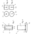
- a neutralizing body 1 with a cover 2, a cover 3 and a pyrotechnic charge 4 is shown in a sectional view.
- the pyrotechnic charge 5 forms a channel 5 as can be seen.
- This exchangeable base 2 can be fastened to the cover 3 .
- the attachment can be made by screwing, clipping, etc.
- a bayonet connection can also be sufficient.
- a mixture that burns very hot and energetically should be selected as the active mass or pyrotechnic charge 4 .
- the shell 3 of the neutralizing body 1 can be round, square, oval, elliptical, etc., with no restrictions being provided. The same applies to the shape of the replaceable bases 6, which should, however, be adapted to the geometric shape of the shell.
- the interchangeable floors 6 can in turn have different geometric nozzle shapes.
- Figures 2 and 3 only excerpts of two possible forms are shown. 2 shows a hole nozzle 7.1, 3 a fan nozzle 7.2.
- the nozzles 7 are placed in the base 7 and form corresponding recesses (openings) in the respective base 6.
- An electrical ignition device 8 or access for a pilot light ignition etc. (not shown in detail) is led out upwards from the cover 2 .
- the pyrotechnic composition 4 burns from the inside out, ie from the duct 5 to the envelope 3. A resulting flame is blown down through the nozzle 7 (7.1, 7.2) out of the bottom 2 of the neutralization body 1. A constant distance from the object 9 to be destroyed is maintained.
- a point nozzle 7.1 is used, for example, to center the power on a point. Different floors 6 with point nozzles 7.1 with different diameters can also be provided here.
- a fan nozzle 7.2 can be used to generate a fanned jet.
- several floors 6 with fan nozzles 7.2 of different lengths/cross sections of the slit of the fan nozzles 7.2 can belong to the kit.
- a point nozzle 7.1 can, for example, be exchanged for a fan nozzle 7.2 and vice versa.
- the bottom 6 is removed from the shell with the point nozzle 7.1 and a bottom 6 is attached to the shell 3 with a fan nozzle 7.2.
- the geometry in the bases 6 can also be crosses, ellipses, squares, ovals, etc., with these bases 6 also being able to be attached to the neutralization body 1 in an interchangeable manner.
- a bottom 6 can be dispensed with. This ensures that a high level of energy is provided in a targeted manner in order to damage the object 9, set it on fire or the like.
- pins or nubs 10 are attached to the casing 3 at least on the bottom face side.
Landscapes
- Engineering & Computer Science (AREA)
- Manufacturing & Machinery (AREA)
- General Engineering & Computer Science (AREA)
- Lighters Containing Fuel (AREA)
Description
- Die Erfindung richtet sich auf einen Bausatz für einen Neutralisierungskörper, auch Anzünder genannt, zur Beseitigung von Minen, Munitionen, pyrotechnischer Munitionen oder Gegenständen. Der Bausatz ist geeignet zur Herstellung bzw. Schaffung des Neutralisierungskörpers. Die Munitionsvernichtung etc. erfolgt häufig durch Initiierung selbiger. Verwendet werden dazu in der Regel Schneid- und Hohlladungen. Pyrotechnische Munition oder offen zugängige Sprengstoffe werden in sogenannten EOD (Explosive Ordnance Disposal) -Anzündern angezündet. Zur Beseitigung von Munition im "Low-order"-Verfahren werden pyrotechnische Anzünder verwendet, um die Außenhülle einer Munition zu durchbrechen und den darin befindlichen Sprengstoff anzuzünden, sodass dieser gefahrlos abbrennen kann.
- Aus der
GB 2 312 864 A - Die
US 3,109,369 A beschreibt eine Vorrichtung zur Beseitigung von umhüllten Explosivstoffen. Diese umfasst einen Behälter zur Aufnahme einer Thermit-Ladung. Bodenseitig ist eine schmale Öffnung mit einer Kappe verschlossen, die zerstört wird, wenn die Ladung zündet. Derartige Vorrichtungen weisen eine geringe Flexibilität auf. Die Ladung wird bei Gebrauch gezündet und brennt von der Spitze ab. Das kann bewirken, dass hier kein konstanter Abstand zur Munition etc. eingehalten wird, mit dem Nachteil, dass nicht die gesamte Energie des pyrotechnischen Satzes auf die Munition aufgebracht wird. In Konsequenz schwindet die Leistung mit der Brennzeit. Zudem besteht das Problem zur Bekämpfung und Beseitigung von Munition, welche eine Ummantelung aus Bakelit oder Ähnlichem aufweist. - Aus der
DE 10 2009 021 820 B4 ist ein Neutralisierungskörper bekannt, der aus zwei Körpern besteht, die ineinander gesetzt, zueinander verdrehbar sind. Mit diesem Körper kann ein seitlicher Längsschlitz oder ein punktueller Austritt im Boden eingestellt werden. Als Wirkmasse wird auch hier eine Thermit-Ladung bevorzugt, die durch Zuschlagstoffe besonders heiß und energiereich abbrennt. Derartige Neutralisationskörper haben sich in der Praxis bewährt. -
US4601761 beschreibt einen Neutralisierungskörper mit einem lösbaren Boden, in dem eine Düse eingebracht ist. - Darauf aufbauend stellt sich der Erfindung die Aufgabe, eine Vorrichtung aufzuzeigen, welche beim Abbrand einen konstanten Abstand zur Munition etc., welche vernichtet werden soll, aufweist.
- Gelöst wird die Aufgabe durch die Merkmale des Patentanspruchs 1. Vorteilhafte Ausgestaltungen sind in den Unteransprüchen aufgezeigt.
- Der Erfindung liegt die Idee zugrunde, verschiedene Deckel als Böden mit unterschiedlichen Düsenformen zum Einsatz an einem Neutralisierungskörper zu bringen, um verschiedene Szenarien bedienen zu können. D.h., mittels der unterschiedlichen Düsenformen im Deckel (bzw. im Boden) ist es möglich, auf die verschiedenen Szenarien erfolgsversprechend und auf diese abgestimmt einwirken zu können. Dabei sollte die Geometrie der Düse auf den Einsatz bzw. einen gewünschten Abbrand abgestimmt sein. Insbesondere kann noch vor Ort die Wahl der Düsenform vorgenommen werden, abstimmbar auf das zu vernichtende Objekt selbst, wozu der Deckel bzw. der Boden auswechselbar gestaltet ist. Die Düsen sind in einem auswechselbaren Boden eingebracht.
- Angedacht ist z.B. eine Düse zum Zentrieren der Leistung auf einen Punkt (Punktdüse). Mit dieser punktuellen Ausrichtung können dicke Munitionshüllen etc. (Objekt) durchdrungen werden. Das Anzünden des in den Hüllen befindlichen Sprengstoffs und das Abbrennen über die gesamte Brennzeit werden sichergestellt.
- Eine weitere andere Düse bzw. Düsenform dient z.B. zum Erzeugen eines gefächerten Strahls. Dabei wird die Energie in Form einer Linie in das Objekt eingebracht. Genutzt werden kann diese Düse zum Öffnen beispielsweise von Munitionshüllen mit einer geringeren Hüllenstärke. Das Einleiten der Verbrennung des Sprengstoffes erfolgt über eine größere Fläche.
- Wird hingegen ein offener Abbrand benötigt, d.h., gezielt ein hohes Maß an Energie, um das Objekt zu schädigen, anzuzünden oder ähnliches, kann auf eine Düse auch verzichtet werden. In diesem Fall kann der Neutralisierungskörper einseitig offen sein.
- Weitere Einsatzmöglichkeiten wie auch weitere Düsenformen bzw. -geometrien sind denkbar, wie Kreuze, Ellipsen, Vierecke, Ovale etc.
- Der Sprengstoff wird in einem Behälter aus Aluminium o. ä. beispielsweise eingepresst, der von einem Stahlbehälter des Neutralisierungskörpers umgeben ist. Alternativ kann der Sprengstoff aber auch direkt im Stahlbehälter untergebracht sein, ggf. auch hier durch Einpressen.
- Die Zusammensetzung des pyrotechnischen Satzes (Sprengstoff) ist so gewählt, dass zum einen eine sehr hohe Hitzeentwicklung zur Durchdringung von Materialien und zur Anzündung von Sprengstoffen entwickelt wird. Zum anderen entwickelt der Satz Gase beim Abbrand, welche den Abtrag des Hüllenmaterials unterstützen.
- Zur Anwendung können hier beispielsweise Sätze mit einem metallischen Brennstoff und einem Oxidationsmittel (z. B. Magnesium und Kaliumnitrat) in einem Mengenverhältnis von ca. 50:50 Gew.% bis 80:20 Gew.% (metallischer Brennstoff: Oxidationsmittel) sowie Sätze auf Basis von Thermitmischungen mit Zusatz von gasbildenden Komponenten (z. B. eine Mischung aus Eisen-Oxid, Magnesium, Kaliumnitrat und einem Binder) kommen.
- Die Ladung selbst hat bevorzugt einen inneren Kanal. Durch diesen Kanal kann die Energie zielgerichtet in den Bereich der bodenseitigen (oder deckelseitigen) Ausblasöffnung (Düse) geführt werden.
- Nach oben (bzw. unten) herausgeführt ist ein Anschluss für einen elektrischen Anzünder oder aber ein Zugang für eine Leitfeuerzündung.
- Der Bodenbereich und / oder der Deckelbereich sollten durch eine Keramik- oder Toneinlage oder dergleichen gegen die starke Hitze (Temperaturbereich < 2800°C) geschützt werden, damit keine weiteren insbesondere ungewollten Ausblasöffnungen entstehen.
- Zudem sollte eine Verdrehsicherung eingebunden werden. Dies können bodenseitig vorhandene Stifte oder Noppen am Behälter sein, damit der Körper nicht aus der gewünschten Position wegbewegt werden kann. Alternativ oder zusätzlich können Ösen zur Anbringung von Verzurrbändern, Riemen, Seilen, Stricken, Gurten etc. zur Verbindung des Anzünders mit dem zu vernichtenden Gegenstand (Objekt) vorgesehen werden.
- Zur Beseitigung von Minen, Munitionen, pyrotechnischer Munitionen oder Gegenständen wird ein Neutralisierungskörper vorgeschlagen, der zumindest aus einem Deckel mit Anzündvorrichtung, einer Hülle, einem in der Hülle gehaltenen pyrotechnischen Satz sowie einem von der Hülle lösbaren Boden mit einer Düse besteht. Verschiedene Böden weisen verschiedene Düsenformen auf. Die Formen der Düse können dabei punktförmig, fächerförmig, kreuzförmig, viereckig, elliptisch, oval etc. sein. Je nach Wunsch und Aufgabenstellung kann der Boden gegen einen anderen Boden ausgetauscht werden. Dadurch kann ein anderer Querschnitt bzw. eine andere geometrische Form der Düse an dem Neutralisierungskörper befestigt werden. So wird es möglich, durch eine individuelle Vorgabe auf die Gegebenheit der zu vernichtenden Gegenstände / Objekte reagieren und den Erfolg einwirken zu können. Ein Bausatz oder System für den Neutralisierungskörper sieht daher zumindest mehrere Böden mit den verschiedenen Düsen vor. Diese können bestimmungsgemäß an dem Behälter des Neutralisierungskörpers befestigt werden. Ein Austausch ist dabei vorgesehen.
- Anhand eines Ausführungsbeispiels mit Zeichnung soll die Erfindung näher erläutert werden. Es zeigt:
- Fig. 1
- einen Neutralisierungskörper in einer Schnittdarstellung,
- Fig. 2
- einen Boden des Neutralisierungskörpers aus
Fig. 1 mit einem Loch als Düse, - Fig. 3
- einen Boden des Neutralisierungskörpers aus
Fig. 1 mit einem Längsschlitz als Düse, - Fig. 4
- den Neutralisierungskörper aus
Fig. 1 in Funktion. - In
Fig. 1 ist ein Neutralisierungskörper 1 mit einem Deckel 2, einer Hülle 3 sowie einem pyrotechnischen Satz 4 in einer Schnittdarstellung dargestellt. Erkennbar bildet der pyrotechnische Satz 5 einen Kanal 5. Mit 6 ist ein wechselbarer Boden mit Düse 7 gekennzeichnet. - Dieser auswechselbare Boden 2 ist an der Hülle 3 befestigbar. Die Befestigung kann mittels Verschraubung, Verklippsung etc. vorgenommen werden. Ausreichend kann auch eine Bajonettverbindung sein. Als Wirkmasse bzw. pyrotechnischer Satz 4 ist eine Mischung zu wählen, welche sehr heiß und energetisch abbrennt.
- Die Hülle 3 des Neutralisierungskörpers 1 kann rund, eckig, oval, elliptisch etc. sein, wobei keine Einschränkungen vorgesehen seind. Gleiches gilt für die Form der auswechselbaren Böden 6, die jedoch an die geometrische Form der Hülle angepasst sein sollte.
- Die wechselbaren Böden 6 können ihrerseits verschiedene geometrische Düsenformen aufweisen. In den
Fig. 2 und 3 sind nur auszugsweise zwei mögliche Formen dargestellt.Fig. 2 zeigt eine Lochdüse 7.1,Fig. 3 eine Fächerdüse 7.2. Die Düsen 7 sind dabei im Boden 7 eingebracht und bilden entsprechende Ausnehmungen (Öffnungen) im jeweiligen Boden 6. - Nach oben aus dem Deckel 2 herausgeführt ist eine elektrische Anzündvorrichtung 8 oder ein Zugang für eine Leitfeuerzündung etc. (nicht näher dargestellt).
-
Fig. 4 zeigt die Neutralisierungskörper 1 im Einsatz. Über die Anzündvorrichtung 8 im Deckel 2 wird die Zündung des pyrotechnischen Satzes 4 eingeleitet. Der pyrotechnische Satz 4 brennt von innen nach außen ab, d. h., vom Kanal 5 zur Hülle 3. Eine entstehende Flamme wird über die Düse 7 (7.1, 7.2) nach unten aus dem Boden 2 des Neutralisierungskörpers 1 ausgeblasen. Dabei wird ein konstanter Abstand zum zu vernichtenden Objekt 9 eingehalten. - Eine Punkt-Düse 7.1 dient beispielsweise zum Zentrieren der Leistung auf einen Punkt. Hier können auch verschiedene Böden 6 mit Punkt-Düsen 7.1 mit unterschiedlichen Durchmessern vorgesehen werden.
- Eine Fächer-Düse 7.2 kann zur Erzeugung eines gefächerten Strahls eingesetzt werden. Auch hier können mehrere Böden 6 mit Fächer-Düsen 7.2 unterschiedlicher Längen / Querschnitte des Schlitzes der Fächer-Düsen 7.2 zum Bausatz gehören.
- Eine Punkt-Düse 7.1 kann beispielsweise gegen eine Fächer-Düse 7.2 ausgetauscht werden und umgekehrt. Dazu wird der Boden 6 mit der Punkt-Düse 7.1 von der Hülle entfernt und ein Boden 6 mit einer Fächerdüse 7.2 an der Hülle 3 befestigt.
- Die Geometrie in den Böden 6 können auch Kreuze, Ellipsen, Vierecke, Ovale etc. sein, wobei auch diese Böden 6 austauschbar an den Neutralisierungskörper 1 angebunden werden können. In der Anwendung des Neutralisierungskörpers kann auf einen Boden 6 verzichtet werden. Dadurch wird erreicht, dass gezielt ein hohes Maß an Energie bereitgestellt wird, um das Objekt 9 zu schädigen, anzuzünden oder ähnliches.
- Als Verdrehsicherung sind zumindest bodenstirnseitig Stifte oder Noppen 10 an der Hülle 3 angebracht.
Claims (6)
- Bausatz für einen Neutralisierungskörper (1), bestehend aus einem Deckel (2) mit Anzündvorrichtung (8), einer Hülle (3), einem in der Hülle (3) gehaltenen pyrotechnischen Satz (4), und verschiedenen von der Hülle (3) lösbaren Böden (6) mit jeweils einer Düse (7, 7.1, 7.2), wobei die Düse (7, 7.1, 7.2) in dem jeweiligen auswechselbaren Boden (6) eingebracht ist, und wobei die verschiedenen Böden (6) verschiedene Düsenformen (7, 7.1, 7.2) aufweisen.
- Bausatz für einen Neutralisationskörper (1) nach Anspruch 1, dadurch gekennzeichnet, dass die Formen der Düse (7) punktförmig (7.1), fächerförmig (7.2), kreuzförmig, viereckig, elliptisch, oval etc. sind.
- Bausatz für einen Neutralisierungskörper nach einem der Ansprüche 1 bis 2, dadurch gekennzeichnet, dass der Bodenbereich und / oder der Deckelbereich durch eine Keramik- oder Toneinlage oder dergleichen gegen die starke Hitze des pyrotechnischen Satzes (4) geschützt werden kann.
- Bausatz für einen Neutralisierungskörper nach einem der Ansprüche 1 bis 3, dadurch gekennzeichnet, dass eine Verdrehsicherung (10) eingebunden ist.
- Bausatz für einen Neutralisierungskörper nach Anspruch 4, dadurch gekennzeichnet, dass als Verdrehsicherung zumindest bodenstirnseitig Stifte oder Noppen (10) an der Hülle (3) angebracht sind.
- Bausatz für einen Neutralisierungskörper nach einem der Ansprüche 1 bis 5, gekennzeichnet durch, Ösen an der Hülle (3) zur Anbringung von Verzurrbändern, Riemen, Seilen, Stricken, Gurten etc.
Applications Claiming Priority (1)
| Application Number | Priority Date | Filing Date | Title |
|---|---|---|---|
| DE102017108833.4A DE102017108833A1 (de) | 2017-04-25 | 2017-04-25 | Neutralisierungskörper |
Publications (2)
| Publication Number | Publication Date |
|---|---|
| EP3396302A1 EP3396302A1 (de) | 2018-10-31 |
| EP3396302B1 true EP3396302B1 (de) | 2022-07-13 |
Family
ID=61906714
Family Applications (1)
| Application Number | Title | Priority Date | Filing Date |
|---|---|---|---|
| EP18165794.1A Active EP3396302B1 (de) | 2017-04-25 | 2018-04-04 | Neutralisierungskörper |
Country Status (2)
| Country | Link |
|---|---|
| EP (1) | EP3396302B1 (de) |
| DE (1) | DE102017108833A1 (de) |
Families Citing this family (1)
| Publication number | Priority date | Publication date | Assignee | Title |
|---|---|---|---|---|
| DE102019111818A1 (de) * | 2019-05-07 | 2020-11-12 | Rheinmetall Waffe Munition Gmbh | Neutralisierungskörper |
Family Cites Families (9)
| Publication number | Priority date | Publication date | Assignee | Title |
|---|---|---|---|---|
| US3109369A (en) | 1944-05-31 | 1963-11-05 | Harold J Plumley | Disposal of encased explosives |
| US4601761A (en) * | 1985-06-17 | 1986-07-22 | The United States Of America As Represented By The Secretary Of The Navy | Nozzle for self-contained cutting torches |
| GB2312864A (en) | 1996-05-09 | 1997-11-12 | Secr Defence | Thermite cutting device |
| US6484617B1 (en) * | 1999-05-10 | 2002-11-26 | Alliant Techsystems Inc. | Assembly and process for controlled burning of landmine without detonation |
| AU2003213629A1 (en) * | 2002-03-01 | 2003-09-16 | Brisant Companies | On-site land mine removal system |
| FR2904105B1 (fr) * | 2006-07-21 | 2008-08-29 | Tda Armements Sas | Dispositif pyrotechnique de destruction de munitions |
| DE102009021820B4 (de) | 2009-05-18 | 2014-01-16 | Rheinmetall Waffe Munition Gmbh | Vorrichtung und Verfahren zur Vernichtung von Munition oder dergleichen |
| WO2014037905A1 (en) * | 2012-09-07 | 2014-03-13 | Kuhn Petrus Gerhardus | Deflagration arrangement for neutralising explosives |
| US9175933B2 (en) * | 2014-02-21 | 2015-11-03 | The United States Of America, As Represented By The Secretary Of The Army | Simple low-cost hand-held landmine neutralization device |
-
2017
- 2017-04-25 DE DE102017108833.4A patent/DE102017108833A1/de not_active Withdrawn
-
2018
- 2018-04-04 EP EP18165794.1A patent/EP3396302B1/de active Active
Also Published As
| Publication number | Publication date |
|---|---|
| EP3396302A1 (de) | 2018-10-31 |
| DE102017108833A1 (de) | 2018-10-25 |
Similar Documents
| Publication | Publication Date | Title |
|---|---|---|
| DE817126C (de) | Vorrichtung zum Lochen von Brunnenrohren, Brunnenschachtwaenden, Brunnenauskleidungen o. dgl. | |
| DE4001864C2 (de) | ||
| DE19944486C2 (de) | Irritationskörper | |
| WO2001008936A1 (de) | Schnurgaserzeuger für einen gassack | |
| DE2842797A1 (de) | Wurfkoerper | |
| EP3396302B1 (de) | Neutralisierungskörper | |
| EP3230682B1 (de) | Zündersystem für handgranaten | |
| DE2932922C2 (de) | Nebelwurfkörper | |
| DE102009021820B4 (de) | Vorrichtung und Verfahren zur Vernichtung von Munition oder dergleichen | |
| EP1983296A2 (de) | Neutralisierungsverfahren für Sprengkörper und Vorrichtung zur Durchführung des Verfahrens | |
| DE1932367C3 (de) | Tragbare Sprengvorrichtung | |
| EP3234495B1 (de) | Anzündsystem für feuerwerkskörper | |
| EP3619495B1 (de) | Handgranate zur erzeugung von rauch | |
| DE2530207B2 (de) | Brandsatz | |
| EP3771881B1 (de) | Pyrotechnischer initiator zum initiieren eines zündschlauches und verfahren zum initiieren eines zündschlauches | |
| EP3966518A1 (de) | Neutralisierungskörper | |
| DE102014109077A1 (de) | Artilleriegeschoss | |
| DE102015009001B4 (de) | Pyrotechnischer Gasgenerator | |
| EP3457076B1 (de) | Wirkkörper mit bremsdeckel | |
| DE249440C (de) | ||
| DE102018124363B4 (de) | Anzündeinheit mit einstellbarer Verzögerungszeit | |
| AT516929B1 (de) | Pyrotechnischer Gasgenerator | |
| AT19194B (de) | Aufschlag- oder Doppelzünder. | |
| DE102010015047B4 (de) | Frühzündvorrichtung zum Abbrennen von Treibstoffen und Explosivstoffen | |
| EP2405229B1 (de) | Verbessertes Zündsystem für pyrotechnische Gegenstände |
Legal Events
| Date | Code | Title | Description |
|---|---|---|---|
| PUAI | Public reference made under article 153(3) epc to a published international application that has entered the european phase |
Free format text: ORIGINAL CODE: 0009012 |
|
| STAA | Information on the status of an ep patent application or granted ep patent |
Free format text: STATUS: THE APPLICATION HAS BEEN PUBLISHED |
|
| AK | Designated contracting states |
Kind code of ref document: A1 Designated state(s): AL AT BE BG CH CY CZ DE DK EE ES FI FR GB GR HR HU IE IS IT LI LT LU LV MC MK MT NL NO PL PT RO RS SE SI SK SM TR |
|
| AX | Request for extension of the european patent |
Extension state: BA ME |
|
| STAA | Information on the status of an ep patent application or granted ep patent |
Free format text: STATUS: REQUEST FOR EXAMINATION WAS MADE |
|
| 17P | Request for examination filed |
Effective date: 20190430 |
|
| RBV | Designated contracting states (corrected) |
Designated state(s): AL AT BE BG CH CY CZ DE DK EE ES FI FR GB GR HR HU IE IS IT LI LT LU LV MC MK MT NL NO PL PT RO RS SE SI SK SM TR |
|
| GRAP | Despatch of communication of intention to grant a patent |
Free format text: ORIGINAL CODE: EPIDOSNIGR1 |
|
| STAA | Information on the status of an ep patent application or granted ep patent |
Free format text: STATUS: GRANT OF PATENT IS INTENDED |
|
| INTG | Intention to grant announced |
Effective date: 20220128 |
|
| RAP3 | Party data changed (applicant data changed or rights of an application transferred) |
Owner name: RHEINMETALL WAFFE MUNITION GMBH |
|
| GRAS | Grant fee paid |
Free format text: ORIGINAL CODE: EPIDOSNIGR3 |
|
| GRAA | (expected) grant |
Free format text: ORIGINAL CODE: 0009210 |
|
| STAA | Information on the status of an ep patent application or granted ep patent |
Free format text: STATUS: THE PATENT HAS BEEN GRANTED |
|
| AK | Designated contracting states |
Kind code of ref document: B1 Designated state(s): AL AT BE BG CH CY CZ DE DK EE ES FI FR GB GR HR HU IE IS IT LI LT LU LV MC MK MT NL NO PL PT RO RS SE SI SK SM TR |
|
| REG | Reference to a national code |
Ref country code: CH Ref legal event code: EP |
|
| REG | Reference to a national code |
Ref country code: DE Ref legal event code: R096 Ref document number: 502018010128 Country of ref document: DE |
|
| REG | Reference to a national code |
Ref country code: AT Ref legal event code: REF Ref document number: 1504488 Country of ref document: AT Kind code of ref document: T Effective date: 20220815 |
|
| REG | Reference to a national code |
Ref country code: IE Ref legal event code: FG4D Free format text: LANGUAGE OF EP DOCUMENT: GERMAN |
|
| REG | Reference to a national code |
Ref country code: LT Ref legal event code: MG9D |
|
| REG | Reference to a national code |
Ref country code: NL Ref legal event code: MP Effective date: 20220713 |
|
| PG25 | Lapsed in a contracting state [announced via postgrant information from national office to epo] |
Ref country code: SE Free format text: LAPSE BECAUSE OF FAILURE TO SUBMIT A TRANSLATION OF THE DESCRIPTION OR TO PAY THE FEE WITHIN THE PRESCRIBED TIME-LIMIT Effective date: 20220713 Ref country code: RS Free format text: LAPSE BECAUSE OF FAILURE TO SUBMIT A TRANSLATION OF THE DESCRIPTION OR TO PAY THE FEE WITHIN THE PRESCRIBED TIME-LIMIT Effective date: 20220713 Ref country code: PT Free format text: LAPSE BECAUSE OF FAILURE TO SUBMIT A TRANSLATION OF THE DESCRIPTION OR TO PAY THE FEE WITHIN THE PRESCRIBED TIME-LIMIT Effective date: 20221114 Ref country code: NO Free format text: LAPSE BECAUSE OF FAILURE TO SUBMIT A TRANSLATION OF THE DESCRIPTION OR TO PAY THE FEE WITHIN THE PRESCRIBED TIME-LIMIT Effective date: 20221013 Ref country code: NL Free format text: LAPSE BECAUSE OF FAILURE TO SUBMIT A TRANSLATION OF THE DESCRIPTION OR TO PAY THE FEE WITHIN THE PRESCRIBED TIME-LIMIT Effective date: 20220713 Ref country code: LV Free format text: LAPSE BECAUSE OF FAILURE TO SUBMIT A TRANSLATION OF THE DESCRIPTION OR TO PAY THE FEE WITHIN THE PRESCRIBED TIME-LIMIT Effective date: 20220713 Ref country code: LT Free format text: LAPSE BECAUSE OF FAILURE TO SUBMIT A TRANSLATION OF THE DESCRIPTION OR TO PAY THE FEE WITHIN THE PRESCRIBED TIME-LIMIT Effective date: 20220713 Ref country code: FI Free format text: LAPSE BECAUSE OF FAILURE TO SUBMIT A TRANSLATION OF THE DESCRIPTION OR TO PAY THE FEE WITHIN THE PRESCRIBED TIME-LIMIT Effective date: 20220713 Ref country code: ES Free format text: LAPSE BECAUSE OF FAILURE TO SUBMIT A TRANSLATION OF THE DESCRIPTION OR TO PAY THE FEE WITHIN THE PRESCRIBED TIME-LIMIT Effective date: 20220713 |
|
| PG25 | Lapsed in a contracting state [announced via postgrant information from national office to epo] |
Ref country code: PL Free format text: LAPSE BECAUSE OF FAILURE TO SUBMIT A TRANSLATION OF THE DESCRIPTION OR TO PAY THE FEE WITHIN THE PRESCRIBED TIME-LIMIT Effective date: 20220713 Ref country code: IS Free format text: LAPSE BECAUSE OF FAILURE TO SUBMIT A TRANSLATION OF THE DESCRIPTION OR TO PAY THE FEE WITHIN THE PRESCRIBED TIME-LIMIT Effective date: 20221113 Ref country code: HR Free format text: LAPSE BECAUSE OF FAILURE TO SUBMIT A TRANSLATION OF THE DESCRIPTION OR TO PAY THE FEE WITHIN THE PRESCRIBED TIME-LIMIT Effective date: 20220713 Ref country code: GR Free format text: LAPSE BECAUSE OF FAILURE TO SUBMIT A TRANSLATION OF THE DESCRIPTION OR TO PAY THE FEE WITHIN THE PRESCRIBED TIME-LIMIT Effective date: 20221014 |
|
| REG | Reference to a national code |
Ref country code: DE Ref legal event code: R097 Ref document number: 502018010128 Country of ref document: DE |
|
| PG25 | Lapsed in a contracting state [announced via postgrant information from national office to epo] |
Ref country code: SM Free format text: LAPSE BECAUSE OF FAILURE TO SUBMIT A TRANSLATION OF THE DESCRIPTION OR TO PAY THE FEE WITHIN THE PRESCRIBED TIME-LIMIT Effective date: 20220713 Ref country code: RO Free format text: LAPSE BECAUSE OF FAILURE TO SUBMIT A TRANSLATION OF THE DESCRIPTION OR TO PAY THE FEE WITHIN THE PRESCRIBED TIME-LIMIT Effective date: 20220713 Ref country code: DK Free format text: LAPSE BECAUSE OF FAILURE TO SUBMIT A TRANSLATION OF THE DESCRIPTION OR TO PAY THE FEE WITHIN THE PRESCRIBED TIME-LIMIT Effective date: 20220713 Ref country code: CZ Free format text: LAPSE BECAUSE OF FAILURE TO SUBMIT A TRANSLATION OF THE DESCRIPTION OR TO PAY THE FEE WITHIN THE PRESCRIBED TIME-LIMIT Effective date: 20220713 |
|
| PLBE | No opposition filed within time limit |
Free format text: ORIGINAL CODE: 0009261 |
|
| STAA | Information on the status of an ep patent application or granted ep patent |
Free format text: STATUS: NO OPPOSITION FILED WITHIN TIME LIMIT |
|
| PG25 | Lapsed in a contracting state [announced via postgrant information from national office to epo] |
Ref country code: SK Free format text: LAPSE BECAUSE OF FAILURE TO SUBMIT A TRANSLATION OF THE DESCRIPTION OR TO PAY THE FEE WITHIN THE PRESCRIBED TIME-LIMIT Effective date: 20220713 Ref country code: EE Free format text: LAPSE BECAUSE OF FAILURE TO SUBMIT A TRANSLATION OF THE DESCRIPTION OR TO PAY THE FEE WITHIN THE PRESCRIBED TIME-LIMIT Effective date: 20220713 |
|
| 26N | No opposition filed |
Effective date: 20230414 |
|
| PG25 | Lapsed in a contracting state [announced via postgrant information from national office to epo] |
Ref country code: AL Free format text: LAPSE BECAUSE OF FAILURE TO SUBMIT A TRANSLATION OF THE DESCRIPTION OR TO PAY THE FEE WITHIN THE PRESCRIBED TIME-LIMIT Effective date: 20220713 |
|
| PG25 | Lapsed in a contracting state [announced via postgrant information from national office to epo] |
Ref country code: SI Free format text: LAPSE BECAUSE OF FAILURE TO SUBMIT A TRANSLATION OF THE DESCRIPTION OR TO PAY THE FEE WITHIN THE PRESCRIBED TIME-LIMIT Effective date: 20220713 |
|
| REG | Reference to a national code |
Ref country code: CH Ref legal event code: PL |
|
| PG25 | Lapsed in a contracting state [announced via postgrant information from national office to epo] |
Ref country code: LU Free format text: LAPSE BECAUSE OF NON-PAYMENT OF DUE FEES Effective date: 20230404 |
|
| REG | Reference to a national code |
Ref country code: BE Ref legal event code: MM Effective date: 20230430 |
|
| PG25 | Lapsed in a contracting state [announced via postgrant information from national office to epo] |
Ref country code: MC Free format text: LAPSE BECAUSE OF FAILURE TO SUBMIT A TRANSLATION OF THE DESCRIPTION OR TO PAY THE FEE WITHIN THE PRESCRIBED TIME-LIMIT Effective date: 20220713 |
|
| PG25 | Lapsed in a contracting state [announced via postgrant information from national office to epo] |
Ref country code: MC Free format text: LAPSE BECAUSE OF FAILURE TO SUBMIT A TRANSLATION OF THE DESCRIPTION OR TO PAY THE FEE WITHIN THE PRESCRIBED TIME-LIMIT Effective date: 20220713 Ref country code: LI Free format text: LAPSE BECAUSE OF NON-PAYMENT OF DUE FEES Effective date: 20230430 Ref country code: IT Free format text: LAPSE BECAUSE OF FAILURE TO SUBMIT A TRANSLATION OF THE DESCRIPTION OR TO PAY THE FEE WITHIN THE PRESCRIBED TIME-LIMIT Effective date: 20220713 Ref country code: CH Free format text: LAPSE BECAUSE OF NON-PAYMENT OF DUE FEES Effective date: 20230430 |
|
| REG | Reference to a national code |
Ref country code: IE Ref legal event code: MM4A |
|
| PG25 | Lapsed in a contracting state [announced via postgrant information from national office to epo] |
Ref country code: BE Free format text: LAPSE BECAUSE OF NON-PAYMENT OF DUE FEES Effective date: 20230430 |
|
| PG25 | Lapsed in a contracting state [announced via postgrant information from national office to epo] |
Ref country code: IE Free format text: LAPSE BECAUSE OF NON-PAYMENT OF DUE FEES Effective date: 20230404 |
|
| PG25 | Lapsed in a contracting state [announced via postgrant information from national office to epo] |
Ref country code: IE Free format text: LAPSE BECAUSE OF NON-PAYMENT OF DUE FEES Effective date: 20230404 |
|
| REG | Reference to a national code |
Ref country code: AT Ref legal event code: MM01 Ref document number: 1504488 Country of ref document: AT Kind code of ref document: T Effective date: 20230404 |
|
| PG25 | Lapsed in a contracting state [announced via postgrant information from national office to epo] |
Ref country code: AT Free format text: LAPSE BECAUSE OF NON-PAYMENT OF DUE FEES Effective date: 20230404 |
|
| PG25 | Lapsed in a contracting state [announced via postgrant information from national office to epo] |
Ref country code: AT Free format text: LAPSE BECAUSE OF NON-PAYMENT OF DUE FEES Effective date: 20230404 |
|
| PG25 | Lapsed in a contracting state [announced via postgrant information from national office to epo] |
Ref country code: BG Free format text: LAPSE BECAUSE OF FAILURE TO SUBMIT A TRANSLATION OF THE DESCRIPTION OR TO PAY THE FEE WITHIN THE PRESCRIBED TIME-LIMIT Effective date: 20220713 |
|
| PG25 | Lapsed in a contracting state [announced via postgrant information from national office to epo] |
Ref country code: BG Free format text: LAPSE BECAUSE OF FAILURE TO SUBMIT A TRANSLATION OF THE DESCRIPTION OR TO PAY THE FEE WITHIN THE PRESCRIBED TIME-LIMIT Effective date: 20220713 |
|
| PGFP | Annual fee paid to national office [announced via postgrant information from national office to epo] |
Ref country code: DE Payment date: 20250422 Year of fee payment: 8 |
|
| PGFP | Annual fee paid to national office [announced via postgrant information from national office to epo] |
Ref country code: GB Payment date: 20250423 Year of fee payment: 8 |
|
| PGFP | Annual fee paid to national office [announced via postgrant information from national office to epo] |
Ref country code: FR Payment date: 20250425 Year of fee payment: 8 |
|
| PG25 | Lapsed in a contracting state [announced via postgrant information from national office to epo] |
Ref country code: CY Free format text: LAPSE BECAUSE OF FAILURE TO SUBMIT A TRANSLATION OF THE DESCRIPTION OR TO PAY THE FEE WITHIN THE PRESCRIBED TIME-LIMIT; INVALID AB INITIO Effective date: 20180404 |
|
| PG25 | Lapsed in a contracting state [announced via postgrant information from national office to epo] |
Ref country code: HU Free format text: LAPSE BECAUSE OF FAILURE TO SUBMIT A TRANSLATION OF THE DESCRIPTION OR TO PAY THE FEE WITHIN THE PRESCRIBED TIME-LIMIT; INVALID AB INITIO Effective date: 20180404 |
|
| PG25 | Lapsed in a contracting state [announced via postgrant information from national office to epo] |
Ref country code: TR Free format text: LAPSE BECAUSE OF FAILURE TO SUBMIT A TRANSLATION OF THE DESCRIPTION OR TO PAY THE FEE WITHIN THE PRESCRIBED TIME-LIMIT Effective date: 20220713 |