EP3396332A1 - Adaptateur de dérivation de compteur - Google Patents
Adaptateur de dérivation de compteur Download PDFInfo
- Publication number
- EP3396332A1 EP3396332A1 EP18165684.4A EP18165684A EP3396332A1 EP 3396332 A1 EP3396332 A1 EP 3396332A1 EP 18165684 A EP18165684 A EP 18165684A EP 3396332 A1 EP3396332 A1 EP 3396332A1
- Authority
- EP
- European Patent Office
- Prior art keywords
- port
- valve element
- meter
- adapter
- flowpath
- Prior art date
- Legal status (The legal status is an assumption and is not a legal conclusion. Google has not performed a legal analysis and makes no representation as to the accuracy of the status listed.)
- Granted
Links
Images




Classifications
-
- G—PHYSICS
- G01—MEASURING; TESTING
- G01F—MEASURING VOLUME, VOLUME FLOW, MASS FLOW OR LIQUID LEVEL; METERING BY VOLUME
- G01F15/00—Details of, or accessories for, apparatus of groups G01F1/00 - G01F13/00 insofar as such details or appliances are not adapted to particular types of such apparatus
- G01F15/18—Supports or connecting means for meters
- G01F15/185—Connecting means, e.g. bypass conduits
-
- F—MECHANICAL ENGINEERING; LIGHTING; HEATING; WEAPONS; BLASTING
- F16—ENGINEERING ELEMENTS AND UNITS; GENERAL MEASURES FOR PRODUCING AND MAINTAINING EFFECTIVE FUNCTIONING OF MACHINES OR INSTALLATIONS; THERMAL INSULATION IN GENERAL
- F16K—VALVES; TAPS; COCKS; ACTUATING-FLOATS; DEVICES FOR VENTING OR AERATING
- F16K11/00—Multiple-way valves, e.g. mixing valves; Pipe fittings incorporating such valves
- F16K11/02—Multiple-way valves, e.g. mixing valves; Pipe fittings incorporating such valves with all movable sealing faces moving as one unit
- F16K11/06—Multiple-way valves, e.g. mixing valves; Pipe fittings incorporating such valves with all movable sealing faces moving as one unit comprising only sliding valves, i.e. sliding closure elements
- F16K11/065—Multiple-way valves, e.g. mixing valves; Pipe fittings incorporating such valves with all movable sealing faces moving as one unit comprising only sliding valves, i.e. sliding closure elements with linearly sliding closure members
-
- F—MECHANICAL ENGINEERING; LIGHTING; HEATING; WEAPONS; BLASTING
- F16—ENGINEERING ELEMENTS AND UNITS; GENERAL MEASURES FOR PRODUCING AND MAINTAINING EFFECTIVE FUNCTIONING OF MACHINES OR INSTALLATIONS; THERMAL INSULATION IN GENERAL
- F16K—VALVES; TAPS; COCKS; ACTUATING-FLOATS; DEVICES FOR VENTING OR AERATING
- F16K11/00—Multiple-way valves, e.g. mixing valves; Pipe fittings incorporating such valves
- F16K11/02—Multiple-way valves, e.g. mixing valves; Pipe fittings incorporating such valves with all movable sealing faces moving as one unit
- F16K11/06—Multiple-way valves, e.g. mixing valves; Pipe fittings incorporating such valves with all movable sealing faces moving as one unit comprising only sliding valves, i.e. sliding closure elements
- F16K11/065—Multiple-way valves, e.g. mixing valves; Pipe fittings incorporating such valves with all movable sealing faces moving as one unit comprising only sliding valves, i.e. sliding closure elements with linearly sliding closure members
- F16K11/0655—Multiple-way valves, e.g. mixing valves; Pipe fittings incorporating such valves with all movable sealing faces moving as one unit comprising only sliding valves, i.e. sliding closure elements with linearly sliding closure members with flat slides
-
- F—MECHANICAL ENGINEERING; LIGHTING; HEATING; WEAPONS; BLASTING
- F16—ENGINEERING ELEMENTS AND UNITS; GENERAL MEASURES FOR PRODUCING AND MAINTAINING EFFECTIVE FUNCTIONING OF MACHINES OR INSTALLATIONS; THERMAL INSULATION IN GENERAL
- F16K—VALVES; TAPS; COCKS; ACTUATING-FLOATS; DEVICES FOR VENTING OR AERATING
- F16K31/00—Actuating devices; Operating means; Releasing devices
- F16K31/44—Mechanical actuating means
- F16K31/53—Mechanical actuating means with toothed gearing
- F16K31/54—Mechanical actuating means with toothed gearing with pinion and rack
-
- G—PHYSICS
- G01—MEASURING; TESTING
- G01F—MEASURING VOLUME, VOLUME FLOW, MASS FLOW OR LIQUID LEVEL; METERING BY VOLUME
- G01F15/00—Details of, or accessories for, apparatus of groups G01F1/00 - G01F13/00 insofar as such details or appliances are not adapted to particular types of such apparatus
- G01F15/18—Supports or connecting means for meters
-
- Y—GENERAL TAGGING OF NEW TECHNOLOGICAL DEVELOPMENTS; GENERAL TAGGING OF CROSS-SECTIONAL TECHNOLOGIES SPANNING OVER SEVERAL SECTIONS OF THE IPC; TECHNICAL SUBJECTS COVERED BY FORMER USPC CROSS-REFERENCE ART COLLECTIONS [XRACs] AND DIGESTS
- Y10—TECHNICAL SUBJECTS COVERED BY FORMER USPC
- Y10T—TECHNICAL SUBJECTS COVERED BY FORMER US CLASSIFICATION
- Y10T137/00—Fluid handling
- Y10T137/598—With repair, tapping, assembly, or disassembly means
- Y10T137/5997—Gas or water meter replacing
Definitions
- the invention relates to gas meters. More particularly, the invention relates to gas meter changeout.
- An exemplary meter has an inlet port/fitting receiving gas flow from a supply line and an outlet port/fitting delivering the gas to a building line.
- the inlet fitting and outlet fitting may be directly connected to respective fittings of the supply line and building line
- common installations use a cast metallic meter bar.
- the meter bar has a first pair or fittings for respectively mating with fittings of the supply line and building line and then a second pair of fittings for respectively mating with the meter fittings (directly or indirectly).
- the second pair may have an on-center spacing the same as a standard on-center spacing of the fittings of the associated class of meter.
- Meters often have to be replaced. When replacing a meter, it is undesirable to terminate all gas flow to the building line. Even if a full flow is not maintained during changeout (changeover), it may be desired to maintain a sufficient flow to keep pilots lit.
- Some changeover systems involve connection to a temporary gas supply such as a portable gas supply. Others involve bypassing the meter. Some bypass systems involve the in situ assembly of a temporary bypass conduit which is subsequently removed. Others are preassembled and remain in place after changeout. An example of these involves bypass meter bars.
- An exemplary such system has a cast body formed essentially as a combination of a pair of elbows and a bypass conduit joining the elbows.
- One elbow has an inlet from the supply line and an outlet to the meter inlet.
- the other elbow has an inlet from the meter outlet and an outlet to the building line.
- the bypass conduit extends between the elbows.
- Each elbow carries a three-way valve.
- An inlet valve has a first condition establishing communication between the supply line and meter while blocking the bypass conduit.
- An outlet valve likewise has a first condition establishing communication between the meter and the building line while blocking the bypass.
- the inlet valve In its second condition, the inlet valve establishes communication between the supply line and the bypass conduit while blocking the meter inlet. In its second condition, the outlet valve establishes communication between the bypass conduit and the building line while blocking the meter outlet. Having both valves in their second conditions is a bypass condition allowing the meter to be removed and replaced. In variations, one or both valves may have additional conditions. To avoid gas theft, the valves may be lockable in their respective first conditions.
- a meter bypass adapter comprising a body having: a first port; a second port; a third port; and a fourth port. At least one valve element is held by the body and moveable between: a first position wherein a flowpath is open from the first port to the second port and a flowpath is open from the third port to the fourth port without a direct flowpath from the first port to the fourth port; and a second position wherein a flowpath extends from the first port to the fourth port bypassing the second port and the third port.
- a single rotary actuator is held by the body to rotate about an axis and, in turn, shift the least one valve element between the first position and the second position.
- the at least one valve element is mounted in the body for a linear shift between the first position and the second position.
- the at least one valve element comprises a first valve element and a second valve element.
- the first valve element and the second valve element each have a toothed rack; and the actuator has a pinion engaged to the toothed rack of the first valve element and the second valve element.
- an assembly comprises the meter bypass adapter and further comprises a gas meter having: an inlet coupled to the second port; and an outlet coupled to the third port.
- the gas meter has a threaded male inlet fitting and a threaded male outlet fitting
- the meter bypass adapter has a threaded male fittings at the first port, the second port, the third port, and the fourth port
- a first male-to-male adapter connects the second port threaded male fitting to the threaded male inlet fitting
- a second male-to-male adapter connects the third port threaded male fitting to the threaded male outlet fitting .
- a method for using the meter bypass adapter comprises: shifting the valve element from the first position to the second position; with the valve element in the second position, decoupling a first gas meter from the second port and third port; with the valve element in the second position, coupling a second gas meter to the second port and third port; and, after the coupling, shifting the valve element from the second position to the first position.
- the shift from the second position to the first position passes through an intermediate condition wherein all four ports are in communication with each other.
- a meter bypass adapter comprising a body having: a first port; a second port; a third port; and a fourth port.
- a first valve element is held by the body and moveable between a first position and a second position.
- a second valve element is held by the body and moveable between a first position and a second position.
- An actuator is coupled to the first valve element and second valve element to synchronize movement of the first valve element and second valve element between their respective first position and second position.
- movement of the first valve element between its first position and its second position is linearly opposite movement of the second valve element between its first position and its second position.
- the actuator comprises a pentagonal socket for receiving a key to rotate the actuator.
- the actuator is a rotary actuator held by the body to rotate about an axis and, in turn, linearly shift the first valve element and the second valve element.
- an assembly comprises the meter bypass adapter and further comprises a gas meter having: an inlet coupled to the second port; and an outlet coupled to the third port.
- the gas meter has a threaded male inlet fitting and a threaded male outlet fitting.
- the meter bypass adapter has a threaded male fittings at the first port, the second port, the third port, and the fourth port.
- a first male-to-male adapter connects the second port threaded male fitting to the threaded male inlet fitting.
- a second male-to-male adapter connects the third port threaded male fitting to the threaded male outlet fitting.
- a method for using meter bypass adapter method comprises: shifting the first valve element and the second valve element from their respective first positions to their respective second positions; with the first valve element and the second valve element in their respective second positions, decoupling a first gas meter from the second port and third port; with the first valve element and the second valve element in their second positions, coupling a second gas meter to the second port and third port; and after the coupling, shifting first valve element and the second valve element to their respective first positions.
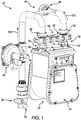
- FIG. 1 shows a gas meter set 20 comprising a meter 22 having a meter housing assembly 24.
- the exemplary meter includes an inlet 26 at an inlet fitting 28 and an outlet 30 at an outlet fitting 32.
- the meter set includes an inlet 34 for connection to a gas supply (e.g., a riser (not shown)) from an underground service line (not shown).
- the exemplary inlet 34 is an inlet of a shutoff valve 36.
- An inlet/supply flowpath 520 extends downstream from the inlet 34 to the meter inlet 26 in a normal mode of operation.
- a pressure regulator 40 is mounted to a tee fitting 42.
- an outlet flowpath 522 extends from the meter outlet 30 to an outlet 44 of the meter set (e.g., at a fitting 46 for connection to a building gas line-not shown).
- Various illustrated pipes and fittings may be of conventional form (e.g., cast iron, steel, or brass pipe and threaded fittings with steel or brass nuts and appropriate gaskets, if any).
- the meter set may be one of many different known or yet-developed configurations to which the present teachings may apply.
- the meter set includes a meter bypass adapter 60 having a housing or body assembly (body) 62.
- the body 62 has multiple ports.
- FIGS. 2 and 3 show a first port 64, a second port 66, a third port 68, and a fourth port 70.
- the first port 64 is an inlet receiving gas along the inlet flowpath from the meter set inlet 34 and through the pressure regulator 40;
- the second port 66 is an outlet to the meter coupled to the meter inlet 26 (e.g., as discussed below);
- the third port 68 is coupled to the meter outlet 30 to receive gas from the meter;
- the fourth port 70 is coupled to an outlet line along the outlet flowpath extending to the meter set outlet 44.
- the exemplary ports 64, 66, 68, and 70 are formed along threaded fittings 74, 76, 78, 80 which, in turn, are connected to adapters to interface with larger threaded fittings of the meter and meter set piping.
- the adapter 60 comprises a rotary actuator 90 coupled to one or more valve elements 92, 94 to shift the one or more valve elements between a plurality of conditions associated with respective modes of operation.
- a first condition is associated with the aforementioned normal mode of operation of the meter wherein the inlet flowpath is open from the first port 64 to the second port 66 and the outlet flowpath is open from the third port 68 to the fourth port 70 without any bypass (i.e., without any direct flowpath from the first port to the fourth port).
- a bypass flowpath from the first port to the fourth port bypassing the second port and the third port.
- this exemplary condition there is no communication between either the first port 64 or the fourth port 70 and the second port 66 or the third port 68.
- This bypass condition allows the meter to be moved and replaced while gas continues to the delivered into the building.
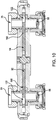
- the exemplary bypass adapter 60 also has a third condition which is a purge condition ( FIGs. 9 and 10 ).
- a purge condition there is communication between all four ports.
- flow directly from the first port 64 to the fourth port 70 may maintain service. This is used to purge a replacement or reinstalled meter of air as is discussed below.
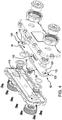
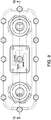
- Each exemplary valve element 92, 94 FIGs. (4 and 5 ) has a first portion 120 bearing a port 122 for passing the associated flow to or from the meter.
- the valve elements have an underside 124 which, along the portion 120, seals relative to the respective port 66 or 68 in the open condition.
- the valve elements have an upper surface 126 which, along the portion 120, seals relative to the respective port 64 or 70 in the open condition.
- the underside 124 is flat, along a sufficient extent, to maintain sealing engagement with the associated port 64 or 68 even in the bypass condition (thus allowing an intact portion of the valve element underside to seal with and block that port).
- FIG. 3 shows the port 122 of the first valve element 92 coaxial about an axis 510 with the respective ports 64 and 66 and the port 122 of the second valve element 94 as coaxial along an axis 512 with the ports 68 and 70 and their associated fittings (discussed below).
- FIG. 2 shows a front-to-back central vertical plane 504 and a lateral central vertical plane 506.
- the axes 510 and 512 fall along the plane 506 and the axis 514 of the rotary actuator 90 falls at the intersection of the planes 504 and 506.
- the rotary actuator serves to actuate the valve elements in directions toward and away from the plane 504.
- the open condition is a maximally retracted condition of the valve elements and the bypass condition is a maximally extended condition.
- the purge condition is an intermediate condition.
- the exemplary rotary actuator 90 ( FIG. 4 ) comprises a pinion gear 140 enmeshed with toothed racks 142 of the respective valve elements 92, 94. Accordingly, rotating the rotary actuator 90 in one direction about its axis of rotation 514 extends the valve elements relative to each other while rotation in the opposite direction retracts them.
- the exemplary housing 62 ( FIG. 3 ) comprises an upper member (upper half) 150 and a lower member (lower half) 152 meeting along a transverse horizontal centerplane 508.
- the exemplary halves 150 and 152 are brass formed by casting and machining or merely machining from bar stock.
- An array of fasteners 160 e.g., screws
- a gasket may seal the two halves along combined slots 164 in mating surfaces 154 and 156.
- the valve elements 92, 94 are held for reciprocal linear motion (e.g., between surfaces 170 and 172 of respective portions of the compartments formed in the two halves.
- the two halves also include respective bores 174 and 176 (the former being a through-bore and the latter being a blind bore) capturing associated upper and lower circular section portions of the actuator 90 to hold it for rotation about the axis 514.
- Bore 174 is open to an exterior (upper) surface of the half 150 to allow driving access to the rotary actuator.
- the exemplary driving access is provided by a five-sided socket 178 in the upper surface of the rotary actuator.
- a five-sided socket is regarded as a security feature equivalent to a lock. This is because five-sided drivers are not commonly available.
- Alternative embodiments may include other actuators (e.g., handles) which, therefore, might have actual external locking features such as a clasp for engagement by a padlock.
- the upper surfaces 126 of the valve elements 92, 94 contain slots 190 ( FIG. 5 ) which align with and become exposed to the ports 64 and 70 in the bypass condition ( FIG. 7 ).
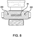
- the slots 190 thus allow flow to pass around the valve elements into chamber portions 200, 202 ( FIG. 8 ), respectively in front of and behind the valve elements.
- flow from the port 64 passes front and back through the first valve element slot 190 then passes front and back along the valve elements through the compartment portions 200 and 202 reentering the ends of the slot 190 of the second valve element to pass out in port 70. In this position, it is seen that intact portions of the underside block the second port and third port from any communication.
- the exemplary fittings 74, 76, 78, 80 are identical and, in the exemplary embodiment, are male threaded fittings of a size equal to or smaller than the smallest anticipated pipe and meter threads to facilitate use of further adapters 240 and 250 ( FIG. 3 ) for mating with specific pipe sizes of the associated installation.
- the fittings 74, 76, 78, 80 are flanged male threaded fittings having hexagonal flanges rotationally locked in associated hexagonal counterbores in the adjacent interior surface of the associated housing half 150 or 152.
- the top (from the point of view of the fitting) surface of each flange bears a groove for capturing a sealing O-ring to seal with the adjacent surface of the associated valve element.
- a radially outwardly open channel Adjacent the underside, a radially outwardly open channel carries another O-ring for sealing with an associated bore in the housing through which the threaded portion protrudes.
- the adapters 240 are female-to-male adapters with a proximal internally threaded portion for mating with the associated externally threaded portion of the fitting 74, 76, 78, 80.
- An externally threaded portion of the adapter 240 is dimensioned to mate with a female fitting of the nominal size of the piping system.
- the fitting 250 is a two-piece fitting comprising a first piece 252 and a second piece 260.
- the first piece 252 has an internally threaded portion mated to the associated threaded portion of fitting 76, 80 and a flange capturing an internally threaded portion 260 of the associated meter fitting 28, 32.
- the exemplary system may be manufactured by machining the various pieces (of which the fittings may be stock items).
- the valve elements 92 and 94 are identical (merely in different orientation). The elements may be assembled such as from the exploded conditions of FIGs. 4 and 5 and screws tightened.
- the adapter could include only a single valve element (i.e., having two apertures for alignment with the two ports and reciprocally moving with a single motion).
- FIG. 2 also shows a purge indicia 188.
- These indicias may be machined in the housing upper half or attached to a boilerplate thereatop (e.g., via screws or rivets).
- the fittings 240 may then be attached to the associated internally-threaded fittings 50, 52 ( FIG. 1 ) of the respective lines to the meter and from the meter.
- the meter may then be installed by tightening the fittings 260 to the associated fitting 28 and 32.
- the system In service, the system is normally run with the bypass adapter in the open condition.
- a technician inserts a complementary five-sided key (not shown) into the socket 174 and rotates the actuator initially to the bypass condition which may involve passing through the purge condition. This blocks the meter. The technician may then loosen the fittings 260 and remove the meter.
- the meter may be serviced or replaced with a replacement meter.
- the technician may tighten only one fitting 260 (e.g., the fitting 260 at port 66 and meter inlet fitting 28).
- the fitting 260 at the meter outlet fitting 30 is left loose.
- the technician may rotate the actuator back to the purge condition and hold for a predetermined time (e.g. in the range of two to five seconds). During this time, flow enters the meter inlet and passes through the meter purging the meter of air which may leak out at the loose fitting 260 at the meter outlet fitting 30.
- the technician then tightens the fitting 260 at the meter outlet fitting 30 and rotates the actuator to the open condition to restore metered service.
- the purge avoids having a slug of air from the meter pass into the building and possibly blow out pilot lights.
- the various components may be made using otherwise conventional or yet-developed materials and techniques.
- first, second, and the like in the description and following claims is for differentiation within the claim only and does not necessarily indicate relative or absolute importance or temporal order. Similarly, the identification in a claim of one element as “first” (or the like) does not preclude such "first” element from identifying an element that is referred to as “second” (or the like) in another claim or in the description.
Landscapes
- Engineering & Computer Science (AREA)
- General Engineering & Computer Science (AREA)
- Mechanical Engineering (AREA)
- Physics & Mathematics (AREA)
- Fluid Mechanics (AREA)
- General Physics & Mathematics (AREA)
- Measuring Volume Flow (AREA)
Applications Claiming Priority (1)
| Application Number | Priority Date | Filing Date | Title |
|---|---|---|---|
| US15/497,527 US10247594B2 (en) | 2017-04-26 | 2017-04-26 | Meter bypass adapter |
Publications (2)
| Publication Number | Publication Date |
|---|---|
| EP3396332A1 true EP3396332A1 (fr) | 2018-10-31 |
| EP3396332B1 EP3396332B1 (fr) | 2019-12-11 |
Family
ID=61906665
Family Applications (1)
| Application Number | Title | Priority Date | Filing Date |
|---|---|---|---|
| EP18165684.4A Active EP3396332B1 (fr) | 2017-04-26 | 2018-04-04 | Adaptateur de dérivation de compteur |
Country Status (3)
| Country | Link |
|---|---|
| US (1) | US10247594B2 (fr) |
| EP (1) | EP3396332B1 (fr) |
| AU (1) | AU2018202819B2 (fr) |
Cited By (1)
| Publication number | Priority date | Publication date | Assignee | Title |
|---|---|---|---|---|
| US11726073B1 (en) | 2022-02-02 | 2023-08-15 | Honeywell International Inc. | Commercial and residential meter bypass system |
Families Citing this family (7)
| Publication number | Priority date | Publication date | Assignee | Title |
|---|---|---|---|---|
| US11060895B2 (en) * | 2017-05-22 | 2021-07-13 | Panasonic Intellectual Property Management Co., Ltd. | Gas meter including a measurement unit in communication with a shutoff valve in an extended section within a meter body |
| US10746406B2 (en) | 2018-09-18 | 2020-08-18 | Georg Fischer Central Plastics Llc | Breaker box assembly |
| US11473957B2 (en) * | 2020-01-02 | 2022-10-18 | Georg Fischer Central Plastics Llc | Meter bypass assembly having a housing including valve bodies rotationally fixed to opposing ends of a shaft |
| US11674605B2 (en) | 2020-05-29 | 2023-06-13 | Mueller International, Llc | Meter bar |
| US11555547B2 (en) | 2021-01-14 | 2023-01-17 | Mueller International, Llc | Revolver bypass valve |
| US11619312B2 (en) | 2021-01-14 | 2023-04-04 | Mueller International, Llc | Revolver bypass valve |
| US12247674B2 (en) * | 2021-01-18 | 2025-03-11 | Chad Heffernan | Eclipse valve assembly |
Citations (4)
| Publication number | Priority date | Publication date | Assignee | Title |
|---|---|---|---|---|
| US48901A (en) * | 1865-07-25 | Improvement in balanced slide-valves | ||
| US3296859A (en) * | 1964-05-20 | 1967-01-10 | Charles W Stewart | Meter bar |
| US5325888A (en) * | 1993-04-30 | 1994-07-05 | Stary Gary M | Pipeline valve transmission apparatus |
| US5785086A (en) * | 1997-07-08 | 1998-07-28 | Boyce; J. Stephen | Valve assembly for metered fluid flow |
Family Cites Families (12)
| Publication number | Priority date | Publication date | Assignee | Title |
|---|---|---|---|---|
| US3386473A (en) * | 1965-05-17 | 1968-06-04 | J J Mooney | By-pass gas meter hanger |
| US3318176A (en) * | 1965-10-21 | 1967-05-09 | Jr Herbert F Geier | Wrench having a pentagonal socket with threaded adjustment means |
| US3946754A (en) | 1974-06-27 | 1976-03-30 | Cook Robert W | Gas meter disconnect device |
| US4327760A (en) | 1980-07-11 | 1982-05-04 | Lancaster James W | Non-interrupting gas meter exchange system |
| US4890645A (en) * | 1987-10-08 | 1990-01-02 | Baroid Technology, Inc. | Rotary shear seal hydraulic valve |
| US5654505A (en) | 1994-10-12 | 1997-08-05 | Southern California Gas Company | Gas meter cabinet and unitary manifold |
| US5992439A (en) * | 1997-02-21 | 1999-11-30 | Mcgill; James C. | Interface apparatus for adapting a gas flow valve to a gas meter |
| US5934304A (en) * | 1998-04-13 | 1999-08-10 | Peterson; Michael H. | Apparatus and method for gas meter bypass |
| US6840493B2 (en) * | 2002-04-03 | 2005-01-11 | Lemuel T. York | Valve actuator |
| US7152621B1 (en) * | 2003-09-19 | 2006-12-26 | R.W. Lyall & Company, Inc. | Integrated gas meters bar device and locking shut-off valve |
| US7347219B2 (en) * | 2005-10-20 | 2008-03-25 | A. Y. Mcdonald Mfg. Co. | Meter bar and metering system |
| US9212752B2 (en) * | 2012-03-26 | 2015-12-15 | Jordan Gardner | Gas bypass device |
-
2017
- 2017-04-26 US US15/497,527 patent/US10247594B2/en active Active
-
2018
- 2018-04-04 EP EP18165684.4A patent/EP3396332B1/fr active Active
- 2018-04-24 AU AU2018202819A patent/AU2018202819B2/en active Active
Patent Citations (4)
| Publication number | Priority date | Publication date | Assignee | Title |
|---|---|---|---|---|
| US48901A (en) * | 1865-07-25 | Improvement in balanced slide-valves | ||
| US3296859A (en) * | 1964-05-20 | 1967-01-10 | Charles W Stewart | Meter bar |
| US5325888A (en) * | 1993-04-30 | 1994-07-05 | Stary Gary M | Pipeline valve transmission apparatus |
| US5785086A (en) * | 1997-07-08 | 1998-07-28 | Boyce; J. Stephen | Valve assembly for metered fluid flow |
Cited By (1)
| Publication number | Priority date | Publication date | Assignee | Title |
|---|---|---|---|---|
| US11726073B1 (en) | 2022-02-02 | 2023-08-15 | Honeywell International Inc. | Commercial and residential meter bypass system |
Also Published As
| Publication number | Publication date |
|---|---|
| EP3396332B1 (fr) | 2019-12-11 |
| US10247594B2 (en) | 2019-04-02 |
| AU2018202819A1 (en) | 2018-11-15 |
| AU2018202819B2 (en) | 2019-04-04 |
| US20180313682A1 (en) | 2018-11-01 |
| NZ741883A (en) | 2019-03-29 |
Similar Documents
| Publication | Publication Date | Title |
|---|---|---|
| EP3396332B1 (fr) | Adaptateur de dérivation de compteur | |
| AU766445B2 (en) | Backflow preventer valve | |
| US4991622A (en) | Multiply configurable backflow preventer | |
| US6178816B1 (en) | Water meter | |
| US7730735B2 (en) | Refrigerant service port valve for air conditioners | |
| US20140299198A1 (en) | Multi-end connector adaptor | |
| US6648009B1 (en) | Tamper-proof ball valve | |
| NZ741883B (en) | Meter bypass adapter | |
| US7841365B2 (en) | Apparatus for controlling flow through a conduit | |
| WO2000050793A1 (fr) | Accessoires de compteur a eau | |
| US10047891B2 (en) | Multi-coupling with serviceable locking mechanism | |
| US3301051A (en) | By-pass fluid meter fitting | |
| CA2589842A1 (fr) | Corps de vanne universel pour liquide | |
| US6767001B2 (en) | Adjustable manifold joining system | |
| US20020166989A1 (en) | Valve assembly | |
| US5785086A (en) | Valve assembly for metered fluid flow | |
| US5083586A (en) | Mounting arrangement for connecting a fluid pressure valve to a pipe bracket by a hollow adapter member | |
| US8186720B2 (en) | Connection module and connector | |
| TWI486535B (zh) | Gas supply collection unit | |
| US20090045369A1 (en) | Plumbing Fitting | |
| JP2003516518A (ja) | 水道メータ取り付け具 | |
| US20250271324A1 (en) | Gas line and meter pressure testing tools and methods | |
| US20130206262A1 (en) | Plumbing Fitting | |
| DE102005006709A1 (de) | Wasserzähleranlage | |
| GB2225824A (en) | Liquid conduit adaptor |
Legal Events
| Date | Code | Title | Description |
|---|---|---|---|
| PUAI | Public reference made under article 153(3) epc to a published international application that has entered the european phase |
Free format text: ORIGINAL CODE: 0009012 |
|
| STAA | Information on the status of an ep patent application or granted ep patent |
Free format text: STATUS: THE APPLICATION HAS BEEN PUBLISHED |
|
| AK | Designated contracting states |
Kind code of ref document: A1 Designated state(s): AL AT BE BG CH CY CZ DE DK EE ES FI FR GB GR HR HU IE IS IT LI LT LU LV MC MK MT NL NO PL PT RO RS SE SI SK SM TR |
|
| AX | Request for extension of the european patent |
Extension state: BA ME |
|
| STAA | Information on the status of an ep patent application or granted ep patent |
Free format text: STATUS: REQUEST FOR EXAMINATION WAS MADE |
|
| 17P | Request for examination filed |
Effective date: 20190220 |
|
| RBV | Designated contracting states (corrected) |
Designated state(s): AL AT BE BG CH CY CZ DE DK EE ES FI FR GB GR HR HU IE IS IT LI LT LU LV MC MK MT NL NO PL PT RO RS SE SI SK SM TR |
|
| RIC1 | Information provided on ipc code assigned before grant |
Ipc: G01F 15/18 20060101AFI20190620BHEP Ipc: F16K 11/065 20060101ALI20190620BHEP Ipc: F16K 31/54 20060101ALI20190620BHEP |
|
| GRAP | Despatch of communication of intention to grant a patent |
Free format text: ORIGINAL CODE: EPIDOSNIGR1 |
|
| STAA | Information on the status of an ep patent application or granted ep patent |
Free format text: STATUS: GRANT OF PATENT IS INTENDED |
|
| INTG | Intention to grant announced |
Effective date: 20190730 |
|
| GRAS | Grant fee paid |
Free format text: ORIGINAL CODE: EPIDOSNIGR3 |
|
| GRAA | (expected) grant |
Free format text: ORIGINAL CODE: 0009210 |
|
| STAA | Information on the status of an ep patent application or granted ep patent |
Free format text: STATUS: THE PATENT HAS BEEN GRANTED |
|
| AK | Designated contracting states |
Kind code of ref document: B1 Designated state(s): AL AT BE BG CH CY CZ DE DK EE ES FI FR GB GR HR HU IE IS IT LI LT LU LV MC MK MT NL NO PL PT RO RS SE SI SK SM TR |
|
| REG | Reference to a national code |
Ref country code: GB Ref legal event code: FG4D |
|
| REG | Reference to a national code |
Ref country code: CH Ref legal event code: EP Ref country code: CH Ref legal event code: NV Representative=s name: GEORG FISCHER AG, CH |
|
| REG | Reference to a national code |
Ref country code: AT Ref legal event code: REF Ref document number: 1212643 Country of ref document: AT Kind code of ref document: T Effective date: 20191215 |
|
| REG | Reference to a national code |
Ref country code: DE Ref legal event code: R096 Ref document number: 602018001531 Country of ref document: DE |
|
| REG | Reference to a national code |
Ref country code: IE Ref legal event code: FG4D |
|
| REG | Reference to a national code |
Ref country code: NL Ref legal event code: MP Effective date: 20191211 |
|
| REG | Reference to a national code |
Ref country code: LT Ref legal event code: MG4D |
|
| PG25 | Lapsed in a contracting state [announced via postgrant information from national office to epo] |
Ref country code: SE Free format text: LAPSE BECAUSE OF FAILURE TO SUBMIT A TRANSLATION OF THE DESCRIPTION OR TO PAY THE FEE WITHIN THE PRESCRIBED TIME-LIMIT Effective date: 20191211 Ref country code: LT Free format text: LAPSE BECAUSE OF FAILURE TO SUBMIT A TRANSLATION OF THE DESCRIPTION OR TO PAY THE FEE WITHIN THE PRESCRIBED TIME-LIMIT Effective date: 20191211 Ref country code: FI Free format text: LAPSE BECAUSE OF FAILURE TO SUBMIT A TRANSLATION OF THE DESCRIPTION OR TO PAY THE FEE WITHIN THE PRESCRIBED TIME-LIMIT Effective date: 20191211 Ref country code: BG Free format text: LAPSE BECAUSE OF FAILURE TO SUBMIT A TRANSLATION OF THE DESCRIPTION OR TO PAY THE FEE WITHIN THE PRESCRIBED TIME-LIMIT Effective date: 20200311 Ref country code: NO Free format text: LAPSE BECAUSE OF FAILURE TO SUBMIT A TRANSLATION OF THE DESCRIPTION OR TO PAY THE FEE WITHIN THE PRESCRIBED TIME-LIMIT Effective date: 20200311 Ref country code: GR Free format text: LAPSE BECAUSE OF FAILURE TO SUBMIT A TRANSLATION OF THE DESCRIPTION OR TO PAY THE FEE WITHIN THE PRESCRIBED TIME-LIMIT Effective date: 20200312 Ref country code: LV Free format text: LAPSE BECAUSE OF FAILURE TO SUBMIT A TRANSLATION OF THE DESCRIPTION OR TO PAY THE FEE WITHIN THE PRESCRIBED TIME-LIMIT Effective date: 20191211 |
|
| PG25 | Lapsed in a contracting state [announced via postgrant information from national office to epo] |
Ref country code: RS Free format text: LAPSE BECAUSE OF FAILURE TO SUBMIT A TRANSLATION OF THE DESCRIPTION OR TO PAY THE FEE WITHIN THE PRESCRIBED TIME-LIMIT Effective date: 20191211 Ref country code: HR Free format text: LAPSE BECAUSE OF FAILURE TO SUBMIT A TRANSLATION OF THE DESCRIPTION OR TO PAY THE FEE WITHIN THE PRESCRIBED TIME-LIMIT Effective date: 20191211 |
|
| PG25 | Lapsed in a contracting state [announced via postgrant information from national office to epo] |
Ref country code: AL Free format text: LAPSE BECAUSE OF FAILURE TO SUBMIT A TRANSLATION OF THE DESCRIPTION OR TO PAY THE FEE WITHIN THE PRESCRIBED TIME-LIMIT Effective date: 20191211 |
|
| PG25 | Lapsed in a contracting state [announced via postgrant information from national office to epo] |
Ref country code: CZ Free format text: LAPSE BECAUSE OF FAILURE TO SUBMIT A TRANSLATION OF THE DESCRIPTION OR TO PAY THE FEE WITHIN THE PRESCRIBED TIME-LIMIT Effective date: 20191211 Ref country code: RO Free format text: LAPSE BECAUSE OF FAILURE TO SUBMIT A TRANSLATION OF THE DESCRIPTION OR TO PAY THE FEE WITHIN THE PRESCRIBED TIME-LIMIT Effective date: 20191211 Ref country code: ES Free format text: LAPSE BECAUSE OF FAILURE TO SUBMIT A TRANSLATION OF THE DESCRIPTION OR TO PAY THE FEE WITHIN THE PRESCRIBED TIME-LIMIT Effective date: 20191211 Ref country code: PT Free format text: LAPSE BECAUSE OF FAILURE TO SUBMIT A TRANSLATION OF THE DESCRIPTION OR TO PAY THE FEE WITHIN THE PRESCRIBED TIME-LIMIT Effective date: 20200506 Ref country code: NL Free format text: LAPSE BECAUSE OF FAILURE TO SUBMIT A TRANSLATION OF THE DESCRIPTION OR TO PAY THE FEE WITHIN THE PRESCRIBED TIME-LIMIT Effective date: 20191211 Ref country code: EE Free format text: LAPSE BECAUSE OF FAILURE TO SUBMIT A TRANSLATION OF THE DESCRIPTION OR TO PAY THE FEE WITHIN THE PRESCRIBED TIME-LIMIT Effective date: 20191211 |
|
| PG25 | Lapsed in a contracting state [announced via postgrant information from national office to epo] |
Ref country code: IS Free format text: LAPSE BECAUSE OF FAILURE TO SUBMIT A TRANSLATION OF THE DESCRIPTION OR TO PAY THE FEE WITHIN THE PRESCRIBED TIME-LIMIT Effective date: 20200411 Ref country code: SK Free format text: LAPSE BECAUSE OF FAILURE TO SUBMIT A TRANSLATION OF THE DESCRIPTION OR TO PAY THE FEE WITHIN THE PRESCRIBED TIME-LIMIT Effective date: 20191211 Ref country code: SM Free format text: LAPSE BECAUSE OF FAILURE TO SUBMIT A TRANSLATION OF THE DESCRIPTION OR TO PAY THE FEE WITHIN THE PRESCRIBED TIME-LIMIT Effective date: 20191211 |
|
| REG | Reference to a national code |
Ref country code: DE Ref legal event code: R097 Ref document number: 602018001531 Country of ref document: DE |
|
| REG | Reference to a national code |
Ref country code: AT Ref legal event code: MK05 Ref document number: 1212643 Country of ref document: AT Kind code of ref document: T Effective date: 20191211 |
|
| PLBE | No opposition filed within time limit |
Free format text: ORIGINAL CODE: 0009261 |
|
| STAA | Information on the status of an ep patent application or granted ep patent |
Free format text: STATUS: NO OPPOSITION FILED WITHIN TIME LIMIT |
|
| PG25 | Lapsed in a contracting state [announced via postgrant information from national office to epo] |
Ref country code: DK Free format text: LAPSE BECAUSE OF FAILURE TO SUBMIT A TRANSLATION OF THE DESCRIPTION OR TO PAY THE FEE WITHIN THE PRESCRIBED TIME-LIMIT Effective date: 20191211 |
|
| 26N | No opposition filed |
Effective date: 20200914 |
|
| PG25 | Lapsed in a contracting state [announced via postgrant information from national office to epo] |
Ref country code: MC Free format text: LAPSE BECAUSE OF FAILURE TO SUBMIT A TRANSLATION OF THE DESCRIPTION OR TO PAY THE FEE WITHIN THE PRESCRIBED TIME-LIMIT Effective date: 20191211 Ref country code: AT Free format text: LAPSE BECAUSE OF FAILURE TO SUBMIT A TRANSLATION OF THE DESCRIPTION OR TO PAY THE FEE WITHIN THE PRESCRIBED TIME-LIMIT Effective date: 20191211 Ref country code: SI Free format text: LAPSE BECAUSE OF FAILURE TO SUBMIT A TRANSLATION OF THE DESCRIPTION OR TO PAY THE FEE WITHIN THE PRESCRIBED TIME-LIMIT Effective date: 20191211 |
|
| PG25 | Lapsed in a contracting state [announced via postgrant information from national office to epo] |
Ref country code: LU Free format text: LAPSE BECAUSE OF NON-PAYMENT OF DUE FEES Effective date: 20200404 |
|
| REG | Reference to a national code |
Ref country code: BE Ref legal event code: MM Effective date: 20200430 |
|
| PG25 | Lapsed in a contracting state [announced via postgrant information from national office to epo] |
Ref country code: BE Free format text: LAPSE BECAUSE OF NON-PAYMENT OF DUE FEES Effective date: 20200430 Ref country code: PL Free format text: LAPSE BECAUSE OF FAILURE TO SUBMIT A TRANSLATION OF THE DESCRIPTION OR TO PAY THE FEE WITHIN THE PRESCRIBED TIME-LIMIT Effective date: 20191211 |
|
| PG25 | Lapsed in a contracting state [announced via postgrant information from national office to epo] |
Ref country code: IE Free format text: LAPSE BECAUSE OF NON-PAYMENT OF DUE FEES Effective date: 20200404 |
|
| PG25 | Lapsed in a contracting state [announced via postgrant information from national office to epo] |
Ref country code: TR Free format text: LAPSE BECAUSE OF FAILURE TO SUBMIT A TRANSLATION OF THE DESCRIPTION OR TO PAY THE FEE WITHIN THE PRESCRIBED TIME-LIMIT Effective date: 20191211 Ref country code: MT Free format text: LAPSE BECAUSE OF FAILURE TO SUBMIT A TRANSLATION OF THE DESCRIPTION OR TO PAY THE FEE WITHIN THE PRESCRIBED TIME-LIMIT Effective date: 20191211 Ref country code: CY Free format text: LAPSE BECAUSE OF FAILURE TO SUBMIT A TRANSLATION OF THE DESCRIPTION OR TO PAY THE FEE WITHIN THE PRESCRIBED TIME-LIMIT Effective date: 20191211 |
|
| PG25 | Lapsed in a contracting state [announced via postgrant information from national office to epo] |
Ref country code: MK Free format text: LAPSE BECAUSE OF FAILURE TO SUBMIT A TRANSLATION OF THE DESCRIPTION OR TO PAY THE FEE WITHIN THE PRESCRIBED TIME-LIMIT Effective date: 20191211 |
|
| P01 | Opt-out of the competence of the unified patent court (upc) registered |
Effective date: 20230529 |
|
| PGFP | Annual fee paid to national office [announced via postgrant information from national office to epo] |
Ref country code: DE Payment date: 20250422 Year of fee payment: 8 |
|
| PGFP | Annual fee paid to national office [announced via postgrant information from national office to epo] |
Ref country code: GB Payment date: 20250423 Year of fee payment: 8 |
|
| PGFP | Annual fee paid to national office [announced via postgrant information from national office to epo] |
Ref country code: IT Payment date: 20250424 Year of fee payment: 8 |
|
| PGFP | Annual fee paid to national office [announced via postgrant information from national office to epo] |
Ref country code: FR Payment date: 20250425 Year of fee payment: 8 |
|
| PGFP | Annual fee paid to national office [announced via postgrant information from national office to epo] |
Ref country code: CH Payment date: 20250501 Year of fee payment: 8 |