EP3396452B1 - Integrierter selfie-stick - Google Patents
Integrierter selfie-stick Download PDFInfo
- Publication number
- EP3396452B1 EP3396452B1 EP16877503.9A EP16877503A EP3396452B1 EP 3396452 B1 EP3396452 B1 EP 3396452B1 EP 16877503 A EP16877503 A EP 16877503A EP 3396452 B1 EP3396452 B1 EP 3396452B1
- Authority
- EP
- European Patent Office
- Prior art keywords
- pin shaft
- stick
- clamping device
- thread
- selfie stick
- Prior art date
- Legal status (The legal status is an assumption and is not a legal conclusion. Google has not performed a legal analysis and makes no representation as to the accuracy of the status listed.)
- Active
Links
- 239000000758 substrate Substances 0.000 claims description 17
- 230000000694 effects Effects 0.000 claims description 5
- 230000004308 accommodation Effects 0.000 claims description 4
- UQMRAFJOBWOFNS-UHFFFAOYSA-N butyl 2-(2,4-dichlorophenoxy)acetate Chemical compound CCCCOC(=O)COC1=CC=C(Cl)C=C1Cl UQMRAFJOBWOFNS-UHFFFAOYSA-N 0.000 description 9
- 238000010586 diagram Methods 0.000 description 7
- 238000000354 decomposition reaction Methods 0.000 description 3
- 230000003247 decreasing effect Effects 0.000 description 2
- 230000009286 beneficial effect Effects 0.000 description 1
- 230000007547 defect Effects 0.000 description 1
- 239000000428 dust Substances 0.000 description 1
- 238000000034 method Methods 0.000 description 1
- 238000012856 packing Methods 0.000 description 1
- 230000002265 prevention Effects 0.000 description 1
- 238000010408 sweeping Methods 0.000 description 1
Images


Classifications
-
- F—MECHANICAL ENGINEERING; LIGHTING; HEATING; WEAPONS; BLASTING
- F16—ENGINEERING ELEMENTS AND UNITS; GENERAL MEASURES FOR PRODUCING AND MAINTAINING EFFECTIVE FUNCTIONING OF MACHINES OR INSTALLATIONS; THERMAL INSULATION IN GENERAL
- F16M—FRAMES, CASINGS OR BEDS OF ENGINES, MACHINES OR APPARATUS, NOT SPECIFIC TO ENGINES, MACHINES OR APPARATUS PROVIDED FOR ELSEWHERE; STANDS; SUPPORTS
- F16M11/00—Stands or trestles as supports for apparatus or articles placed thereon ; Stands for scientific apparatus such as gravitational force meters
- F16M11/02—Heads
- F16M11/04—Means for attachment of apparatus; Means allowing adjustment of the apparatus relatively to the stand
- F16M11/06—Means for attachment of apparatus; Means allowing adjustment of the apparatus relatively to the stand allowing pivoting
- F16M11/10—Means for attachment of apparatus; Means allowing adjustment of the apparatus relatively to the stand allowing pivoting around a horizontal axis
-
- G—PHYSICS
- G03—PHOTOGRAPHY; CINEMATOGRAPHY; ANALOGOUS TECHNIQUES USING WAVES OTHER THAN OPTICAL WAVES; ELECTROGRAPHY; HOLOGRAPHY
- G03B—APPARATUS OR ARRANGEMENTS FOR TAKING PHOTOGRAPHS OR FOR PROJECTING OR VIEWING THEM; APPARATUS OR ARRANGEMENTS EMPLOYING ANALOGOUS TECHNIQUES USING WAVES OTHER THAN OPTICAL WAVES; ACCESSORIES THEREFOR
- G03B17/00—Details of cameras or camera bodies; Accessories therefor
- G03B17/56—Accessories
-
- G—PHYSICS
- G03—PHOTOGRAPHY; CINEMATOGRAPHY; ANALOGOUS TECHNIQUES USING WAVES OTHER THAN OPTICAL WAVES; ELECTROGRAPHY; HOLOGRAPHY
- G03B—APPARATUS OR ARRANGEMENTS FOR TAKING PHOTOGRAPHS OR FOR PROJECTING OR VIEWING THEM; APPARATUS OR ARRANGEMENTS EMPLOYING ANALOGOUS TECHNIQUES USING WAVES OTHER THAN OPTICAL WAVES; ACCESSORIES THEREFOR
- G03B17/00—Details of cameras or camera bodies; Accessories therefor
- G03B17/56—Accessories
- G03B17/561—Support related camera accessories
-
- F—MECHANICAL ENGINEERING; LIGHTING; HEATING; WEAPONS; BLASTING
- F16—ENGINEERING ELEMENTS AND UNITS; GENERAL MEASURES FOR PRODUCING AND MAINTAINING EFFECTIVE FUNCTIONING OF MACHINES OR INSTALLATIONS; THERMAL INSULATION IN GENERAL
- F16M—FRAMES, CASINGS OR BEDS OF ENGINES, MACHINES OR APPARATUS, NOT SPECIFIC TO ENGINES, MACHINES OR APPARATUS PROVIDED FOR ELSEWHERE; STANDS; SUPPORTS
- F16M11/00—Stands or trestles as supports for apparatus or articles placed thereon ; Stands for scientific apparatus such as gravitational force meters
- F16M11/02—Heads
- F16M11/04—Means for attachment of apparatus; Means allowing adjustment of the apparatus relatively to the stand
- F16M11/041—Allowing quick release of the apparatus
-
- F—MECHANICAL ENGINEERING; LIGHTING; HEATING; WEAPONS; BLASTING
- F16—ENGINEERING ELEMENTS AND UNITS; GENERAL MEASURES FOR PRODUCING AND MAINTAINING EFFECTIVE FUNCTIONING OF MACHINES OR INSTALLATIONS; THERMAL INSULATION IN GENERAL
- F16M—FRAMES, CASINGS OR BEDS OF ENGINES, MACHINES OR APPARATUS, NOT SPECIFIC TO ENGINES, MACHINES OR APPARATUS PROVIDED FOR ELSEWHERE; STANDS; SUPPORTS
- F16M11/00—Stands or trestles as supports for apparatus or articles placed thereon ; Stands for scientific apparatus such as gravitational force meters
- F16M11/20—Undercarriages with or without wheels
- F16M11/24—Undercarriages with or without wheels changeable in height or length of legs, also for transport only, e.g. by means of tubes screwed into each other
- F16M11/38—Undercarriages with or without wheels changeable in height or length of legs, also for transport only, e.g. by means of tubes screwed into each other by folding, e.g. pivoting or scissors tong mechanisms
-
- F—MECHANICAL ENGINEERING; LIGHTING; HEATING; WEAPONS; BLASTING
- F16—ENGINEERING ELEMENTS AND UNITS; GENERAL MEASURES FOR PRODUCING AND MAINTAINING EFFECTIVE FUNCTIONING OF MACHINES OR INSTALLATIONS; THERMAL INSULATION IN GENERAL
- F16M—FRAMES, CASINGS OR BEDS OF ENGINES, MACHINES OR APPARATUS, NOT SPECIFIC TO ENGINES, MACHINES OR APPARATUS PROVIDED FOR ELSEWHERE; STANDS; SUPPORTS
- F16M13/00—Other supports for positioning apparatus or articles; Means for steadying hand-held apparatus or articles
-
- F—MECHANICAL ENGINEERING; LIGHTING; HEATING; WEAPONS; BLASTING
- F16—ENGINEERING ELEMENTS AND UNITS; GENERAL MEASURES FOR PRODUCING AND MAINTAINING EFFECTIVE FUNCTIONING OF MACHINES OR INSTALLATIONS; THERMAL INSULATION IN GENERAL
- F16M—FRAMES, CASINGS OR BEDS OF ENGINES, MACHINES OR APPARATUS, NOT SPECIFIC TO ENGINES, MACHINES OR APPARATUS PROVIDED FOR ELSEWHERE; STANDS; SUPPORTS
- F16M13/00—Other supports for positioning apparatus or articles; Means for steadying hand-held apparatus or articles
- F16M13/04—Other supports for positioning apparatus or articles; Means for steadying hand-held apparatus or articles for supporting on, or holding steady relative to, a person, e.g. by chains, e.g. rifle butt or pistol grip supports, supports attached to the chest or head
-
- G—PHYSICS
- G03—PHOTOGRAPHY; CINEMATOGRAPHY; ANALOGOUS TECHNIQUES USING WAVES OTHER THAN OPTICAL WAVES; ELECTROGRAPHY; HOLOGRAPHY
- G03B—APPARATUS OR ARRANGEMENTS FOR TAKING PHOTOGRAPHS OR FOR PROJECTING OR VIEWING THEM; APPARATUS OR ARRANGEMENTS EMPLOYING ANALOGOUS TECHNIQUES USING WAVES OTHER THAN OPTICAL WAVES; ACCESSORIES THEREFOR
- G03B17/00—Details of cameras or camera bodies; Accessories therefor
- G03B17/56—Accessories
- G03B17/563—Camera grips, handles
-
- H—ELECTRICITY
- H04—ELECTRIC COMMUNICATION TECHNIQUE
- H04M—TELEPHONIC COMMUNICATION
- H04M1/00—Substation equipment, e.g. for use by subscribers
- H04M1/02—Constructional features of telephone sets
- H04M1/11—Supports for sets, e.g. incorporating armrests
-
- H—ELECTRICITY
- H04—ELECTRIC COMMUNICATION TECHNIQUE
- H04M—TELEPHONIC COMMUNICATION
- H04M1/00—Substation equipment, e.g. for use by subscribers
- H04M1/02—Constructional features of telephone sets
- H04M1/11—Supports for sets, e.g. incorporating armrests
- H04M1/12—Adjustable supports, e.g. extensible
- H04M1/13—Adjustable supports, e.g. extensible pantographic
-
- F—MECHANICAL ENGINEERING; LIGHTING; HEATING; WEAPONS; BLASTING
- F16—ENGINEERING ELEMENTS AND UNITS; GENERAL MEASURES FOR PRODUCING AND MAINTAINING EFFECTIVE FUNCTIONING OF MACHINES OR INSTALLATIONS; THERMAL INSULATION IN GENERAL
- F16M—FRAMES, CASINGS OR BEDS OF ENGINES, MACHINES OR APPARATUS, NOT SPECIFIC TO ENGINES, MACHINES OR APPARATUS PROVIDED FOR ELSEWHERE; STANDS; SUPPORTS
- F16M2200/00—Details of stands or supports
- F16M2200/02—Locking means
- F16M2200/021—Locking means for rotational movement
- F16M2200/022—Locking means for rotational movement by friction
-
- F—MECHANICAL ENGINEERING; LIGHTING; HEATING; WEAPONS; BLASTING
- F16—ENGINEERING ELEMENTS AND UNITS; GENERAL MEASURES FOR PRODUCING AND MAINTAINING EFFECTIVE FUNCTIONING OF MACHINES OR INSTALLATIONS; THERMAL INSULATION IN GENERAL
- F16M—FRAMES, CASINGS OR BEDS OF ENGINES, MACHINES OR APPARATUS, NOT SPECIFIC TO ENGINES, MACHINES OR APPARATUS PROVIDED FOR ELSEWHERE; STANDS; SUPPORTS
- F16M2200/00—Details of stands or supports
- F16M2200/02—Locking means
- F16M2200/025—Locking means for translational movement
- F16M2200/027—Locking means for translational movement by friction
-
- H—ELECTRICITY
- H04—ELECTRIC COMMUNICATION TECHNIQUE
- H04M—TELEPHONIC COMMUNICATION
- H04M1/00—Substation equipment, e.g. for use by subscribers
- H04M1/02—Constructional features of telephone sets
- H04M1/04—Supports for telephone transmitters or receivers
Definitions
- the invention relates to a selfie device, and particularly relates to an integrated selfie stick.
- a selfie stick as known from e.g. US9170473 or CN 204 442 465 U , which is a selfie stick sweeping the world, can extend and retract arbitrarily between a length of 20cm-120cm, and a user can realize multi-angle selfie through a remote controller only by fixing a mobile phone or an instamatic on an extendable stick.
- the selfie stick is equipped with a clamping device for clamping the mobile phone or a tablet computer and an extendable stick, wherein the clamping device is fixed at an active end of the extendable stick.
- the volume of the selfie stick should be reduced when not in use, so as to enhance the convenience; therefore, a folding selfie stick is emerged in the market.
- the folding selfie stick folds the clamping device on the extendable stick, but in such structure, the clamping device still have many protruding places, in this way, the integrity is relatively poor, and the appearance effect is bad, and meanwhile, a hand bag/handbag is easily scratched by the protruding part of the clamping device when the folded selfie stick is put in the hand bag/handbag and others accommodating articles, therefore, its convenient use is poor, and the user experience is bad.
- the invention aims at providing an integrated selfie stick to overcome defects of existing art, so as to improve the integrity, appearance and the convenient use.
- the integrated selfie stick comprises a long-cylinder handle shell, an extendable stick fixed on the handle shell, a clamping device which can be folded relative to the extendable stick and a folding device for connecting an active end of the extendable stick and the clamping device, wherein a cavity for accommodating the clamping device is left between an inner wall of the handle shell and an outer wall of the extendable stick; and when the selfie stick is in a pack-up state, the clamping device is folded on the extendable stick, the active end of the extendable stick is retracted back to the handle shell, and the clamping device is placed in the cavity.
- the handle shell comprises an inner shell and a transparent outer shell, wherein the inner shell is fixed in the outer shell, the extendable stick is fixed in the inner shell, and the cavity is located in between an inner wall of the inner shell and the outer wall of the extendable stick.
- a decorative ring is disposed on an outer wall of the handle shell, and a groove for installing a key is arranged on a position of the corresponding decorative ring on the outer wall of the handle shell.
- rotatable opening and closing or a dismountable top cover is arranged on the handle shell, and the top cover is covered on the handle shell when the selfie stick is in a pack-up state.
- the folding device comprises a connector for fixedly connecting the active end of the extendable stick of the selfie stick, a pin shaft is fixed on the connector, the clamping device comprises a substrate and a lower clamp plate fixed at a lower part of the substrate, a connecting cylinder for the pin shaft to penetrate through is arranged at a bottom surface of the lower clamp plate, and a channel for the lower clamp plate to pass through when the clamping device overturns round the pin shaft is arranged between the pin shaft of the connector and a body of the connector.
- the clamping device further comprises an upper clamping arm which can move relative to the substrate, and the upper clamping arm is disposed on an upper part of the substrate.
- the upper clamping arm is equipped with two symmetrical parts, an accommodation tank for accommodating the extendable stick when folding is formed between the two parts.
- two hangers arranged symmetrically are arranged on the connector, the pin shaft penetrates through the two hangers, and the channel is surrounded by the two hangers, the pin shaft and the body of the connector.
- a cross section of one end of the pin shaft is pentagonal, and a pentagonal through hole for nesting in a pentagonal end of the pin shaft is arranged on the hanger.
- the folding device further comprises a thread column and a thread cylinder with an internal thread hole, wherein an external thread is arranged at a front end of the thread column, and a rear end of the thread column is nested in the pin shaft; and when the clamping device is locked, the external thread of the thread column is in a threaded connection with the internal thread hole of the thread cylinder, a cylinder opening of the thread cylinder abuts against an outer wall of the connecting cylinder, and a mutual pressing force is generated by an inner wall of the connecting cylinder and the pin shaft under an effect of a thrust of the thread cylinder, to realize locking.
- the connecting cylinder is divided into two parts with the same size axially along the pin shaft, and a gap for the thread column to penetrate through and allowing the thread column to rotate round a center shaft of the pin shaft is left between the two parts.
- a slot for accommodating a connection plug is arranged in a middle position of a lower part of the substrate.
- the utility model has the beneficial effects that: the extendable stick and the clamping device are surrounded by a cylindrical shell in the utility model, in this way, the clamping device cannot have the protruding part; and the selfie stick is just a complete long cylinder when packing up, therefore, the integrity is very good, and the appearance effect is greatly improved; and moreover, it is not scratched when putting in a hand bag/hangbag, therefore, the convenient use and user experience are improved.
- a selfie stick of the present embodiment comprises a long-cylinder handle shell 40, an extendable stick 30 fixed on the handle shell 40, a clamping device 10 which can be folded relative to the extendable stick 30 and a folding device 20 for connecting an active end of the extendable stick 30 and the clamping device 10.
- a section of the hand shell 40 in the present embodiment is square, and can also be round, polygonal and others in other embodiments.
- the handle shell 40 comprises an inner shell 42 and a transparent outer shell 41, wherein the inner shell 42 is fixed in the outer shell 41, the extendable stick 30 is fixed in the inner shell 41.
- a decorative ring 44 is disposed on an outer wall of the handle shell 40, and a groove 411 ( Fig. 2 ) for installing a key is arranged on a position of the corresponding decorative ring 44 on the outer wall of the handle shell 40.
- a cavity 43 for accommodating the clamping device 10 is left between an inner wall of the inner shell 42 of the handle shell 40 and an outer wall of the extendable stick 30.
- a fixed sleeve 45 for fixing the extendable stick 30 is further arranged in the inner shell 42.
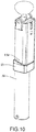
- FIG. 1 when the selfie stick is in a full unfolding state, the active end of the extendable stick 30 stretches out, and clamping device 10 rotates and open from the extendable stick 30. And when the selfie stick is packed up, clamping device 10 is folded toward the extendable stick 30, and then, the active end of the extendable stick 30 is pushed toward the handle shell 40. Finally, when the selfie stick is in a full pack-up state, the clamping device 10 is folded on the extendable stick 30, the active end of the extendable stick 30 is retracted back to the handle shell 40, and the clamping device 10 is placed in the cavity 43.
- rotatable opening and closing or a dismountable top cover is arranged on the handle shell, and the top cover is covered on the handle shell to cover the folding device and the clamping device when the selfie stick is in the full pack-up state.
- a top cover 26 is arranged on the folding device 20 to play a role of protection and dust prevention.
- the clamping device 10 comprises a substrate 14, a lower clamp plate 12 fixed at a lower part of the substrate 14, and an upper clamping arm 13.
- the upper clamping arm 13 is disposed on an upper part of the substrate 14.
- the upper clamping arm 13 and the lower clamp plate 12 are configured to clamp two sides of a mobile phone or a tablet computer and other portable shooting equipment.
- the upper clamping arm 13 can move relative to the substrate 14, so that a spacing between the upper clamping arm 13 and the lower clamp plate 12 is adjustable, so as to adapt to the portable shooting equipment having different widths.
- the upper clamping arm 13 can move relative to the substrate 14, and the lower clamp plate 12 is relatively fixed with the substrate 14.
- a specific structure that the upper clamping arm 13 can move relative to the substrate 14 belongs to the existing art, so no more detailed description is provided here.
- the selfie stick can realize the control of the shooting equipment through a line control, so, a connection and a connection plug are inevitably provided.
- a slot 141 for accommodating the connection plug is arranged in a middle position of a lower part of the substrate 14, so as to enable the connection plug not to shake arbitrarily, as shown in Fig. 4 and Fig. 5 .
- the upper clamping arm 13 is equipped with two symmetrical parts, and an accommodation tank 130 for accommodating the extendable stick when folding is formed between the two parts.
- the folding device 20 comprises a connector 24 configured to fixedly connected with the active end of the extendable stick.
- the connector 24 comprises a body 240 and two hangers 241 arranged symmetrically.
- a pin shaft 25 is fixed on the connector 24, and penetrates through the two hangers 241.
- a connecting cylinder 11 for the pin shaft 25 to penetrate through is arranged at a bottom surface of the lower clamp plate 12.
- a channel 243 for the lower clamp plate 12 o pass through when the clamping device 10 overturns round the pin shaft 25 is arranged between the pin shaft 25 of the connector 24 and the body 240 of the connector 24, and is surrounded by the two hangers 241, the pin shaft 25 and the body 240 of the connector 24.
- the clamping device 10 When the clamping device 10 is folded along a direction of Fig. 4 until to be fully folded (namely, the accommodation tank 130 of the upper clamping arm 13 shown in Fig. 10 is nested on the extendable stick 30), the lower clamp plate 12 is disposed in the channel 243, therefore, the folding area can be greatly reduced.
- the axial rotational degree of freedom of the pin shaft 25 is zero.
- a cross section of an end 251 of the pin shaft 25 is pentagonal, and a pentagonal through hole 242 for nesting in a pentagonal end 251 of the pin shaft 25 is arranged on the hanger 241. After the end 251 of the pin shaft 25 is inserted into the through hole 242 of the hanger 241, the pin shaft 25 cannot rotate relative to the hanger 241.
- the two ends of the pin shaft can be made into pentagon.
- the folding device 20 of the present embodiment further comprises a thread column 21 and a thread cylinder 22 with an internal thread hole.
- an external thread is arranged at a front end of the thread column 21, and a rear end of the thread column 2 is nested in the pin shaft 25; and when the clamping device is locked; and the thread column 21 can rotate round a center shaft of the pin shaft 25.
- the internal thread hole of the thread cylinder 22 is matched with an external thread of the thread column 21. That is, the external thread of the thread column 21 is in a threaded connection with the internal thread hole of the thread cylinder 22, therefore, the thread column 21 can screw in or out of the internal thread hole of the thread cylinder 22.
- a handle 23 is fixed at an outer end of the thread cylinder 22, which can improve the usage experience when screwing the thread cylinder 22 or pulling the thread cylinder 22, and can also improve the appearance effect.
- a connecting cylinder 11 for the pin shaft 25 to penetrate through is arranged at an end of the clamping device 10.
- the connecting cylinder 11 is divided into two parts with the same size axially along the pin shaft 25, and a gap 12 for the thread column 21 to penetrate through and allowing the thread column 21 to rotate round a center shaft of the pin shaft 25 is left between the two parts.
Landscapes
- Engineering & Computer Science (AREA)
- General Engineering & Computer Science (AREA)
- Mechanical Engineering (AREA)
- Physics & Mathematics (AREA)
- General Physics & Mathematics (AREA)
- Signal Processing (AREA)
- Purses, Travelling Bags, Baskets, Or Suitcases (AREA)
- Mutual Connection Of Rods And Tubes (AREA)
Claims (11)
- Integrierter Selfie-Stab (1), bestehend aus einer Langzylinder-Griffhülle (40), einem ausziehbaren Stab (30), der an der Griffhülle befestigt ist, einer Klemmvorrichtung (10), die relativ zu dem ausziehbaren Stab zusammengeklappt werden kann, und einer Klappvorrichtung zum Verbinden eines aktiven Endes des ausziehbaren Stabes und der Klemmvorrichtung, wobei zwischen einer Innenwand der Griffhülle und einer Außenwand des ausziehbaren Stabes ein Hohlraum (43) zum Unterbringen der Klemmvorrichtung freigelassen ist, dadurch gekennzeichnet, dass die Klemmvorrichtung, wenn sich der Selfie-Stab in einem verpackten Zustand befindet, auf den ausziehbaren Stab geklappt ist, wobei das aktive Ende des ausziehbaren Stabes zur Griffhülle zurückgezogen ist und die Klemmvorrichtung in dem Hohlraum platziert ist.
- Integrierter Selfie-Stab nach Anspruch 1, wobei die Griffhülle eine innere Hülle und eine transparente äußere Hülle umfasst, wobei die innere Hülle in der äußeren Hülle befestigt ist, wobei der ausziehbare Stab in der inneren Hülle befestigt ist und der Hohlraum zwischen einer Innenwand der inneren Hülle und der Außenwand des ausziehbaren Stabes angeordnet ist.
- Integrierter Selfie-Stab nach Anspruch 1, wobei auf einer Außenwand der Griffhülle ein dekorativer Ring angeordnet ist, und an einer Position des entsprechenden dekorativen Rings an der Außenwand der Griffhülle eine Rille zum Anbringen einer Passfeder angeordnet ist.
- Integrierter Selfie-Stab nach Anspruch 1, wobei an der Griffhülle eine drehbare, öffnende oder verschließende oder eine demontierbare obere Abdeckung angeordnet ist und die obere Abdeckung die Griffhülle bedeckt, wenn sich der Selfie-Stab in einem verpackten Zustand befindet.
- Integrierter Selfie-Stab nach Anspruch 1, wobei die Klappvorrichtung ein Verbindungsstück für das feste Verbinden des aktiven Endes des ausziehbaren Stabes des Selfie-Stabes umfasst, wobei an dem Verbindungsstück eine Stiftwelle befestigt ist, wobei die Klemmvorrichtung ein Substrat und eine untere Klemmplatte umfasst, die an einem unteren Teil des Substrats befestigt ist, wobei an einer Unterseite der unteren Klemmplatte ein Verbindungszylinder für die Stiftwelle zum Hindurchtreten angeordnet ist, und zwischen der Stiftwelle des Verbindungsstücks und einem Körper des Verbindungsstücks ein Kanal zum Hindurchtreten der unteren Klemmplatte beim Überschlag der Klemmvorrichtung um die Stiftwelle angeordnet ist.
- Integrierter Selfie-Stab nach Anspruch 5, wobei die Klemmvorrichtung ferner einen oberen Klemmarm umfasst, der sich relativ zum Substrat bewegen kann, und wobei der obere Klemmarm an einem oberen Teil des Substrats angeordnet ist.
- Integrierter Selfie-Stab nach Anspruch 6, wobei der obere Klemmarm mit zwei symmetrischen Teilen ausgestattet ist, wobei zwischen den zwei Teilen ein Unterbringungstank zum Unterbringen des ausziehbaren Stabes beim Zusammenklappen gebildet ist.
- Integrierter Selfie-Stab nach Anspruch 5, wobei an dem Verbindungsstück zwei symmetrisch angeordnete Aufhänger angeordnet sind, wobei die Stiftwelle durch die zwei Aufhänger hindurchtritt und der Kanal von den zwei Aufhängern, der Stiftwelle und dem Körper des Verbindungsstücks umgeben ist.
- Integrierter Selfie-Stab nach Anspruch 8, wobei ein Querschnitt eines Endes der Stiftwelle fünfeckig ist und an dem Aufhänger eine fünfeckige Durchgangsöffnung zum Einsetzen eines fünfeckigen Endes der Stiftwelle angeordnet ist.
- Integrierter Selfie-Stab nach einem der Ansprüche 5 bis 9, wobei die Klappvorrichtung ferner eine Gewindesäule und einen Gewindezylinder mit einer Innengewindeöffnung umfasst, wobei an einem vorderen Ende der Gewindesäule ein Außengewinde angeordnet ist und ein hinteres Ende der Gewindesäule in die Stiftwelle eingesetzt ist und wenn die Klemmvorrichtung arretiert ist, sich das Außengewinde der Gewindesäule in einer Gewindeverbindung mit der Innengewindeöffnung des Gewindezylinders befindet, wobei eine Zylinderöffnung des Gewindezylinders an eine Außenwand des Verbindungszylinders stößt und durch eine Innenwand des Verbindungszylinders und die Stiftwelle unter Einwirkung eines Schubs des Gewindezylinders eine gegenseitige Druckkraft erzeugt wird, um die Arretierung umzusetzen.
- Integrierter Selfie-Stab nach Anspruch 10, wobei der Verbindungszylinder axial entlang der Stiftwelle in zwei Teile gleicher Größe geteilt ist und zwischen den zwei Teilen ein Spalt für die Gewindesäule zum Hindurchtreten und zum Ermöglichen der Drehung der Gewindesäule um eine Mittelwelle der Stiftwelle freigelassen ist.
Applications Claiming Priority (2)
| Application Number | Priority Date | Filing Date | Title |
|---|---|---|---|
| CN201521080484.1U CN205232329U (zh) | 2015-12-23 | 2015-12-23 | 一体式自拍杆 |
| PCT/CN2016/105271 WO2017107692A1 (zh) | 2015-12-23 | 2016-11-10 | 一体式自拍杆 |
Publications (3)
| Publication Number | Publication Date |
|---|---|
| EP3396452A1 EP3396452A1 (de) | 2018-10-31 |
| EP3396452A4 EP3396452A4 (de) | 2019-08-21 |
| EP3396452B1 true EP3396452B1 (de) | 2020-07-29 |
Family
ID=55907368
Family Applications (1)
| Application Number | Title | Priority Date | Filing Date |
|---|---|---|---|
| EP16877503.9A Active EP3396452B1 (de) | 2015-12-23 | 2016-11-10 | Integrierter selfie-stick |
Country Status (10)
| Country | Link |
|---|---|
| US (1) | US10012342B2 (de) |
| EP (1) | EP3396452B1 (de) |
| JP (1) | JP3219247U (de) |
| KR (1) | KR20170002376U (de) |
| CN (1) | CN205232329U (de) |
| DE (1) | DE212016000250U1 (de) |
| ES (1) | ES1232197Y (de) |
| RU (1) | RU185834U1 (de) |
| TW (1) | TWM539015U (de) |
| WO (1) | WO2017107692A1 (de) |
Cited By (1)
| Publication number | Priority date | Publication date | Assignee | Title |
|---|---|---|---|---|
| US12235569B1 (en) | 2023-02-24 | 2025-02-25 | Carl Robert Hoerger | Integrated selfie attachment |
Families Citing this family (48)
| Publication number | Priority date | Publication date | Assignee | Title |
|---|---|---|---|---|
| CN205232329U (zh) * | 2015-12-23 | 2016-05-11 | 深圳市随身秀时尚创意科技有限公司 | 一体式自拍杆 |
| CN107426375A (zh) * | 2016-05-24 | 2017-12-01 | 华东交通大学 | 一种多功能自拍杆 |
| CN205919076U (zh) * | 2016-07-01 | 2017-02-01 | 深圳市浩瀚卓越科技有限公司 | 可调重心的稳定器 |
| MX2019001522A (es) * | 2016-08-07 | 2019-06-13 | Stikbox Tech Limited | Telefono movil y panel posterior para el mismo, transformable en brazo para autofoto retractil. |
| USD866558S1 (en) * | 2016-11-11 | 2019-11-12 | Samsung Electronics Co., Ltd. | SSD storage device |
| USD822754S1 (en) * | 2016-12-30 | 2018-07-10 | Guixiong Fang | Selfie stick |
| CN106641626B (zh) * | 2017-01-16 | 2019-11-22 | 陈文穆 | 便携自拍杆 |
| USD843433S1 (en) * | 2017-05-16 | 2019-03-19 | Vitec Holdings Italia Srl | Pan and tilt body with device mounting clamp |
| KR101914868B1 (ko) * | 2017-06-19 | 2018-11-02 | 박용태 | 셀카기능을 가지는 등산스틱 |
| CN108513606B (zh) | 2017-07-31 | 2020-05-05 | 深圳市大疆灵眸科技有限公司 | 云台拍摄器 |
| USD863289S1 (en) * | 2017-08-28 | 2019-10-15 | Shenzhen Sen Xiyuan Technology Co., Ltd | Selfie device |
| CN107606448B (zh) * | 2017-09-01 | 2023-06-13 | 东莞欧森隆数码有限公司 | 一种自拍装置 |
| USD841724S1 (en) * | 2017-09-05 | 2019-02-26 | Xiang HUANG | Selfie stick |
| CN207471091U (zh) * | 2017-09-19 | 2018-06-08 | 深圳市大疆创新科技有限公司 | 支架装置 |
| CN207200854U (zh) * | 2017-09-19 | 2018-04-06 | 深圳市大疆创新科技有限公司 | 便携式手柄 |
| CN107701895A (zh) * | 2017-10-25 | 2018-02-16 | 深圳市法码尔科技开发有限公司 | 夹持装置及自拍杆 |
| USD852872S1 (en) * | 2017-11-21 | 2019-07-02 | Guixiong Fang | Selfie stick |
| USD852873S1 (en) * | 2017-11-21 | 2019-07-02 | Guixiong Fang | Selfie stick |
| USD851163S1 (en) * | 2017-12-21 | 2019-06-11 | Shenzhen Haohualianhe Technology Co., Ltd. | Selfie stick |
| USD863411S1 (en) * | 2017-12-26 | 2019-10-15 | Guilin Zhishen Information Technology Co., Ltd. | Stabilizer |
| JP1618305S (de) * | 2017-12-26 | 2018-11-19 | ||
| USD857786S1 (en) * | 2018-01-08 | 2019-08-27 | SZ DJI Technology Co., Ltd. | Gimbal |
| CN209557997U (zh) * | 2018-06-27 | 2019-10-29 | 深圳市豪华联合科技有限公司 | 支架及具有其的自拍杆 |
| USD901051S1 (en) * | 2018-09-19 | 2020-11-03 | Spyridon Petratos | Flashlight with scroll-wheel dimmer |
| CN109185640B (zh) * | 2018-11-13 | 2024-08-16 | 杨鹏 | 可折弯控制的伸缩杆 |
| CN209638742U (zh) * | 2019-01-08 | 2019-11-15 | 源德盛塑胶电子(深圳)有限公司 | 一种自拍装置 |
| TWD199103S (zh) * | 2019-01-18 | 2019-08-11 | 奕方企業股份有限公司 | 手機固定裝置 |
| JP1655653S (de) * | 2019-02-15 | 2020-03-23 | ||
| CN110131533B (zh) * | 2019-03-25 | 2020-09-08 | 南京溧水高新创业投资管理有限公司 | 一种方便控制的自拍杆 |
| CN210266648U (zh) * | 2019-03-27 | 2020-04-07 | 源德盛塑胶电子(深圳)有限公司 | 一种夹持机构及手持云台 |
| CN110266867A (zh) * | 2019-04-22 | 2019-09-20 | 上海稳奇电脑有限公司 | 一种防滑固定自拍杆 |
| CN110278308B (zh) * | 2019-04-23 | 2020-09-04 | 南京溧水高新创业投资管理有限公司 | 一种自拍杆结构 |
| KR102227565B1 (ko) * | 2019-04-23 | 2021-03-12 | 김제훈 | 지지부가 구비된 셀카봉용 케이스 |
| CN110278309B (zh) * | 2019-04-23 | 2020-09-22 | 金华东阳玖润信息科技有限公司 | 一种自拍设备 |
| USD921096S1 (en) * | 2019-05-15 | 2021-06-01 | Shenzhen Haohualianhe Technology Co., Ltd. | Selfie stick |
| USD909455S1 (en) * | 2019-06-19 | 2021-02-02 | Jinghua Shan | Camera stabilizer |
| RU194603U1 (ru) * | 2019-09-30 | 2019-12-17 | Общество с ограниченной ответственностью «Модуль» | Устройство управления видеоэндоскопом для осмотра фитингов контейнеров и фитинговых упоров железнодорожных платформ |
| USD946563S1 (en) * | 2019-10-21 | 2022-03-22 | Innoplay Limited | Smart holder for mobile phone or camera |
| USD923689S1 (en) * | 2019-11-20 | 2021-06-29 | Dongguan Osm Digital Co. | Selfie stick |
| CN211525898U (zh) * | 2019-12-19 | 2020-09-18 | 广东百诺影像科技工业有限公司 | 一种带手机夹功能的快装板 |
| CN212251923U (zh) * | 2020-01-20 | 2020-12-29 | 深圳市全天拍科技有限公司 | 带有副手柄的拍摄设备支架 |
| CN212776713U (zh) * | 2020-05-27 | 2021-03-23 | 深圳市元素创达科技有限公司 | 手柄滑动结构及应用其的自拍杆 |
| CN213028148U (zh) * | 2020-06-29 | 2021-04-20 | 源德盛塑胶电子(深圳)有限公司 | 一种手机夹持装置 |
| US12142898B2 (en) * | 2020-09-24 | 2024-11-12 | Honeywell International Inc. | Adjustable electric insulating device |
| USD1017670S1 (en) * | 2022-02-16 | 2024-03-12 | Xing Wang | Gimbal or handheld quadropod |
| USD1002709S1 (en) * | 2022-06-20 | 2023-10-24 | Guixiong Fang | Selfie stick |
| US11931883B1 (en) | 2023-04-07 | 2024-03-19 | Eddie N Sons Investments Llc | Reach extending tool system |
| USD1109223S1 (en) * | 2024-08-01 | 2026-01-13 | Zhongshan Vndefo Technology Co., Ltd. | Selfie stick |
Family Cites Families (12)
| Publication number | Priority date | Publication date | Assignee | Title |
|---|---|---|---|---|
| DE202011004245U1 (de) * | 2011-03-22 | 2011-09-01 | Wilhelm Wennmann | VideoHandy+CO-Führungssystem |
| GB201216944D0 (en) * | 2012-09-21 | 2012-11-07 | Beaumont John W | QuadPod. Compact camera/smart phone cradle for anglers |
| CN204119349U (zh) * | 2014-09-11 | 2015-01-21 | 源德盛塑胶电子(深圳)有限公司 | 一种一体式自拍装置 |
| US9473190B1 (en) * | 2015-03-06 | 2016-10-18 | Jason Sandlofer | Phone case with built-in holder |
| CN204442465U (zh) * | 2015-03-16 | 2015-07-01 | 侯雁 | 一种手机自拍杆 |
| US10859894B2 (en) * | 2015-05-19 | 2020-12-08 | Stikbox Technologies Ltd. | Transformable accessory for a handheld digital device |
| CN204756380U (zh) * | 2015-06-29 | 2015-11-11 | 东莞市金弘美电子有限公司 | 一种方便收纳控制伸缩和分离拍照的自拍装置 |
| CN204906489U (zh) * | 2015-08-28 | 2015-12-23 | 比亚迪股份有限公司 | 一种自拍杆 |
| CN205081834U (zh) * | 2015-10-29 | 2016-03-09 | 上虞市宇洋摄影器材有限公司 | 一种自拍杆装置 |
| CN205304916U (zh) * | 2015-11-27 | 2016-06-08 | 中山品创塑胶制品有限公司 | 一种可拆卸式自拍杆 |
| CN205232329U (zh) * | 2015-12-23 | 2016-05-11 | 深圳市随身秀时尚创意科技有限公司 | 一体式自拍杆 |
| CN105657096A (zh) * | 2016-03-07 | 2016-06-08 | 杨腾飞 | 手机自拍杆 |
-
2015
- 2015-12-23 CN CN201521080484.1U patent/CN205232329U/zh not_active Expired - Fee Related
-
2016
- 2016-10-27 TW TW105216373U patent/TWM539015U/zh not_active IP Right Cessation
- 2016-11-07 KR KR2020160006490U patent/KR20170002376U/ko not_active Ceased
- 2016-11-10 US US15/569,091 patent/US10012342B2/en not_active Expired - Fee Related
- 2016-11-10 JP JP2018600070U patent/JP3219247U/ja not_active Expired - Fee Related
- 2016-11-10 DE DE212016000250.3U patent/DE212016000250U1/de not_active Expired - Lifetime
- 2016-11-10 EP EP16877503.9A patent/EP3396452B1/de active Active
- 2016-11-10 RU RU2018126382U patent/RU185834U1/ru active
- 2016-11-10 WO PCT/CN2016/105271 patent/WO2017107692A1/zh not_active Ceased
- 2016-11-10 ES ES201890014U patent/ES1232197Y/es not_active Expired - Fee Related
Non-Patent Citations (1)
| Title |
|---|
| None * |
Cited By (1)
| Publication number | Priority date | Publication date | Assignee | Title |
|---|---|---|---|---|
| US12235569B1 (en) | 2023-02-24 | 2025-02-25 | Carl Robert Hoerger | Integrated selfie attachment |
Also Published As
| Publication number | Publication date |
|---|---|
| ES1232197U9 (es) | 2019-10-01 |
| RU185834U1 (ru) | 2018-12-19 |
| DE212016000250U1 (de) | 2018-08-02 |
| US10012342B2 (en) | 2018-07-03 |
| TWM539015U (zh) | 2017-04-01 |
| JP3219247U (ja) | 2018-12-13 |
| ES1232197U (es) | 2019-07-09 |
| WO2017107692A1 (zh) | 2017-06-29 |
| CN205232329U (zh) | 2016-05-11 |
| KR20170002376U (ko) | 2017-07-03 |
| ES1232197Y (es) | 2019-10-07 |
| US20180066792A1 (en) | 2018-03-08 |
| EP3396452A1 (de) | 2018-10-31 |
| EP3396452A4 (de) | 2019-08-21 |
Similar Documents
| Publication | Publication Date | Title |
|---|---|---|
| EP3396452B1 (de) | Integrierter selfie-stick | |
| CN205931112U (zh) | 一种锁紧机构及折叠车 | |
| CN206427191U (zh) | 折叠机构及具有其的滑板车 | |
| KR200496057Y1 (ko) | 노트북 컴퓨터 거치대 | |
| JP4564104B1 (ja) | 収納容器 | |
| CN209725636U (zh) | 一种夹持装置 | |
| CN108591753A (zh) | 一种显示设备 | |
| CN104879639A (zh) | 多功能便携式手机自拍杆 | |
| CN207364615U (zh) | 夹持装置及自拍杆 | |
| CN204861628U (zh) | 旅行箱旋转拉杆 | |
| CN203952666U (zh) | 一种弯臂遮阳伞 | |
| CN203709734U (zh) | 一种带折叠杯把的水杯 | |
| CN207544822U (zh) | 一种家用筷子筒 | |
| CN206206946U (zh) | 一种伸缩自拍杆 | |
| CN212617313U (zh) | 一种地理信息采集装置 | |
| CN207251736U (zh) | 自拍装置 | |
| CN213392796U (zh) | 滑旋折叠支撑机构及其电器设备 | |
| CN209521816U (zh) | 滑板车把手组件与端盖的连接结构 | |
| CN222797211U (zh) | 一种便携式可折叠围挡 | |
| CN107373943A (zh) | 一种带有可伸缩三脚架的伞把 | |
| CN211844754U (zh) | 一种折叠式滑板车 | |
| CN204713160U (zh) | 儿童推车 | |
| KR20170028465A (ko) | 디자인을 편리하게 변경할 수 있는 스탠딩 우산 | |
| CN203291446U (zh) | 一种两杆的收折结构及使用该收折结构的室内跑步机 | |
| CN201465055U (zh) | 弹出式折叠手写笔 |
Legal Events
| Date | Code | Title | Description |
|---|---|---|---|
| STAA | Information on the status of an ep patent application or granted ep patent |
Free format text: STATUS: THE INTERNATIONAL PUBLICATION HAS BEEN MADE |
|
| PUAI | Public reference made under article 153(3) epc to a published international application that has entered the european phase |
Free format text: ORIGINAL CODE: 0009012 |
|
| STAA | Information on the status of an ep patent application or granted ep patent |
Free format text: STATUS: REQUEST FOR EXAMINATION WAS MADE |
|
| 17P | Request for examination filed |
Effective date: 20180723 |
|
| AK | Designated contracting states |
Kind code of ref document: A1 Designated state(s): AL AT BE BG CH CY CZ DE DK EE ES FI FR GB GR HR HU IE IS IT LI LT LU LV MC MK MT NL NO PL PT RO RS SE SI SK SM TR |
|
| AX | Request for extension of the european patent |
Extension state: BA ME |
|
| DAV | Request for validation of the european patent (deleted) | ||
| DAX | Request for extension of the european patent (deleted) | ||
| A4 | Supplementary search report drawn up and despatched |
Effective date: 20190719 |
|
| RIC1 | Information provided on ipc code assigned before grant |
Ipc: H04N 5/232 20060101ALI20190715BHEP Ipc: F16M 11/04 20060101ALI20190715BHEP Ipc: H04M 1/13 20060101ALI20190715BHEP Ipc: G03B 17/56 20060101AFI20190715BHEP Ipc: F16M 13/04 20060101ALI20190715BHEP |
|
| GRAP | Despatch of communication of intention to grant a patent |
Free format text: ORIGINAL CODE: EPIDOSNIGR1 |
|
| STAA | Information on the status of an ep patent application or granted ep patent |
Free format text: STATUS: GRANT OF PATENT IS INTENDED |
|
| INTG | Intention to grant announced |
Effective date: 20200217 |
|
| GRAJ | Information related to disapproval of communication of intention to grant by the applicant or resumption of examination proceedings by the epo deleted |
Free format text: ORIGINAL CODE: EPIDOSDIGR1 |
|
| STAA | Information on the status of an ep patent application or granted ep patent |
Free format text: STATUS: REQUEST FOR EXAMINATION WAS MADE |
|
| INTC | Intention to grant announced (deleted) | ||
| GRAR | Information related to intention to grant a patent recorded |
Free format text: ORIGINAL CODE: EPIDOSNIGR71 |
|
| GRAS | Grant fee paid |
Free format text: ORIGINAL CODE: EPIDOSNIGR3 |
|
| STAA | Information on the status of an ep patent application or granted ep patent |
Free format text: STATUS: GRANT OF PATENT IS INTENDED |
|
| GRAA | (expected) grant |
Free format text: ORIGINAL CODE: 0009210 |
|
| STAA | Information on the status of an ep patent application or granted ep patent |
Free format text: STATUS: THE PATENT HAS BEEN GRANTED |
|
| INTG | Intention to grant announced |
Effective date: 20200617 |
|
| AK | Designated contracting states |
Kind code of ref document: B1 Designated state(s): AL AT BE BG CH CY CZ DE DK EE ES FI FR GB GR HR HU IE IS IT LI LT LU LV MC MK MT NL NO PL PT RO RS SE SI SK SM TR |
|
| REG | Reference to a national code |
Ref country code: CH Ref legal event code: EP |
|
| REG | Reference to a national code |
Ref country code: AT Ref legal event code: REF Ref document number: 1296490 Country of ref document: AT Kind code of ref document: T Effective date: 20200815 |
|
| REG | Reference to a national code |
Ref country code: IE Ref legal event code: FG4D |
|
| REG | Reference to a national code |
Ref country code: DE Ref legal event code: R096 Ref document number: 602016041081 Country of ref document: DE |
|
| REG | Reference to a national code |
Ref country code: LT Ref legal event code: MG4D |
|
| REG | Reference to a national code |
Ref country code: NL Ref legal event code: MP Effective date: 20200729 |
|
| REG | Reference to a national code |
Ref country code: AT Ref legal event code: MK05 Ref document number: 1296490 Country of ref document: AT Kind code of ref document: T Effective date: 20200729 |
|
| PG25 | Lapsed in a contracting state [announced via postgrant information from national office to epo] |
Ref country code: AT Free format text: LAPSE BECAUSE OF FAILURE TO SUBMIT A TRANSLATION OF THE DESCRIPTION OR TO PAY THE FEE WITHIN THE PRESCRIBED TIME-LIMIT Effective date: 20200729 Ref country code: SE Free format text: LAPSE BECAUSE OF FAILURE TO SUBMIT A TRANSLATION OF THE DESCRIPTION OR TO PAY THE FEE WITHIN THE PRESCRIBED TIME-LIMIT Effective date: 20200729 Ref country code: BG Free format text: LAPSE BECAUSE OF FAILURE TO SUBMIT A TRANSLATION OF THE DESCRIPTION OR TO PAY THE FEE WITHIN THE PRESCRIBED TIME-LIMIT Effective date: 20201029 Ref country code: HR Free format text: LAPSE BECAUSE OF FAILURE TO SUBMIT A TRANSLATION OF THE DESCRIPTION OR TO PAY THE FEE WITHIN THE PRESCRIBED TIME-LIMIT Effective date: 20200729 Ref country code: NO Free format text: LAPSE BECAUSE OF FAILURE TO SUBMIT A TRANSLATION OF THE DESCRIPTION OR TO PAY THE FEE WITHIN THE PRESCRIBED TIME-LIMIT Effective date: 20201029 Ref country code: FI Free format text: LAPSE BECAUSE OF FAILURE TO SUBMIT A TRANSLATION OF THE DESCRIPTION OR TO PAY THE FEE WITHIN THE PRESCRIBED TIME-LIMIT Effective date: 20200729 Ref country code: PT Free format text: LAPSE BECAUSE OF FAILURE TO SUBMIT A TRANSLATION OF THE DESCRIPTION OR TO PAY THE FEE WITHIN THE PRESCRIBED TIME-LIMIT Effective date: 20201130 Ref country code: LT Free format text: LAPSE BECAUSE OF FAILURE TO SUBMIT A TRANSLATION OF THE DESCRIPTION OR TO PAY THE FEE WITHIN THE PRESCRIBED TIME-LIMIT Effective date: 20200729 Ref country code: ES Free format text: LAPSE BECAUSE OF FAILURE TO SUBMIT A TRANSLATION OF THE DESCRIPTION OR TO PAY THE FEE WITHIN THE PRESCRIBED TIME-LIMIT Effective date: 20200729 Ref country code: GR Free format text: LAPSE BECAUSE OF FAILURE TO SUBMIT A TRANSLATION OF THE DESCRIPTION OR TO PAY THE FEE WITHIN THE PRESCRIBED TIME-LIMIT Effective date: 20201030 |
|
| PGFP | Annual fee paid to national office [announced via postgrant information from national office to epo] |
Ref country code: GB Payment date: 20201020 Year of fee payment: 5 Ref country code: FR Payment date: 20201119 Year of fee payment: 5 |
|
| PG25 | Lapsed in a contracting state [announced via postgrant information from national office to epo] |
Ref country code: LV Free format text: LAPSE BECAUSE OF FAILURE TO SUBMIT A TRANSLATION OF THE DESCRIPTION OR TO PAY THE FEE WITHIN THE PRESCRIBED TIME-LIMIT Effective date: 20200729 Ref country code: PL Free format text: LAPSE BECAUSE OF FAILURE TO SUBMIT A TRANSLATION OF THE DESCRIPTION OR TO PAY THE FEE WITHIN THE PRESCRIBED TIME-LIMIT Effective date: 20200729 Ref country code: RS Free format text: LAPSE BECAUSE OF FAILURE TO SUBMIT A TRANSLATION OF THE DESCRIPTION OR TO PAY THE FEE WITHIN THE PRESCRIBED TIME-LIMIT Effective date: 20200729 Ref country code: IS Free format text: LAPSE BECAUSE OF FAILURE TO SUBMIT A TRANSLATION OF THE DESCRIPTION OR TO PAY THE FEE WITHIN THE PRESCRIBED TIME-LIMIT Effective date: 20201129 |
|
| PG25 | Lapsed in a contracting state [announced via postgrant information from national office to epo] |
Ref country code: NL Free format text: LAPSE BECAUSE OF FAILURE TO SUBMIT A TRANSLATION OF THE DESCRIPTION OR TO PAY THE FEE WITHIN THE PRESCRIBED TIME-LIMIT Effective date: 20200729 |
|
| PG25 | Lapsed in a contracting state [announced via postgrant information from national office to epo] |
Ref country code: SM Free format text: LAPSE BECAUSE OF FAILURE TO SUBMIT A TRANSLATION OF THE DESCRIPTION OR TO PAY THE FEE WITHIN THE PRESCRIBED TIME-LIMIT Effective date: 20200729 Ref country code: IT Free format text: LAPSE BECAUSE OF FAILURE TO SUBMIT A TRANSLATION OF THE DESCRIPTION OR TO PAY THE FEE WITHIN THE PRESCRIBED TIME-LIMIT Effective date: 20200729 Ref country code: EE Free format text: LAPSE BECAUSE OF FAILURE TO SUBMIT A TRANSLATION OF THE DESCRIPTION OR TO PAY THE FEE WITHIN THE PRESCRIBED TIME-LIMIT Effective date: 20200729 Ref country code: RO Free format text: LAPSE BECAUSE OF FAILURE TO SUBMIT A TRANSLATION OF THE DESCRIPTION OR TO PAY THE FEE WITHIN THE PRESCRIBED TIME-LIMIT Effective date: 20200729 Ref country code: DK Free format text: LAPSE BECAUSE OF FAILURE TO SUBMIT A TRANSLATION OF THE DESCRIPTION OR TO PAY THE FEE WITHIN THE PRESCRIBED TIME-LIMIT Effective date: 20200729 Ref country code: CZ Free format text: LAPSE BECAUSE OF FAILURE TO SUBMIT A TRANSLATION OF THE DESCRIPTION OR TO PAY THE FEE WITHIN THE PRESCRIBED TIME-LIMIT Effective date: 20200729 |
|
| REG | Reference to a national code |
Ref country code: DE Ref legal event code: R097 Ref document number: 602016041081 Country of ref document: DE |
|
| PG25 | Lapsed in a contracting state [announced via postgrant information from national office to epo] |
Ref country code: AL Free format text: LAPSE BECAUSE OF FAILURE TO SUBMIT A TRANSLATION OF THE DESCRIPTION OR TO PAY THE FEE WITHIN THE PRESCRIBED TIME-LIMIT Effective date: 20200729 |
|
| REG | Reference to a national code |
Ref country code: DE Ref legal event code: R119 Ref document number: 602016041081 Country of ref document: DE |
|
| PLBE | No opposition filed within time limit |
Free format text: ORIGINAL CODE: 0009261 |
|
| STAA | Information on the status of an ep patent application or granted ep patent |
Free format text: STATUS: NO OPPOSITION FILED WITHIN TIME LIMIT |
|
| PG25 | Lapsed in a contracting state [announced via postgrant information from national office to epo] |
Ref country code: MC Free format text: LAPSE BECAUSE OF FAILURE TO SUBMIT A TRANSLATION OF THE DESCRIPTION OR TO PAY THE FEE WITHIN THE PRESCRIBED TIME-LIMIT Effective date: 20200729 Ref country code: SK Free format text: LAPSE BECAUSE OF FAILURE TO SUBMIT A TRANSLATION OF THE DESCRIPTION OR TO PAY THE FEE WITHIN THE PRESCRIBED TIME-LIMIT Effective date: 20200729 |
|
| REG | Reference to a national code |
Ref country code: CH Ref legal event code: PL |
|
| 26N | No opposition filed |
Effective date: 20210430 |
|
| PG25 | Lapsed in a contracting state [announced via postgrant information from national office to epo] |
Ref country code: LU Free format text: LAPSE BECAUSE OF NON-PAYMENT OF DUE FEES Effective date: 20201110 |
|
| REG | Reference to a national code |
Ref country code: BE Ref legal event code: MM Effective date: 20201130 |
|
| PG25 | Lapsed in a contracting state [announced via postgrant information from national office to epo] |
Ref country code: CH Free format text: LAPSE BECAUSE OF NON-PAYMENT OF DUE FEES Effective date: 20201130 Ref country code: SI Free format text: LAPSE BECAUSE OF FAILURE TO SUBMIT A TRANSLATION OF THE DESCRIPTION OR TO PAY THE FEE WITHIN THE PRESCRIBED TIME-LIMIT Effective date: 20200729 Ref country code: LI Free format text: LAPSE BECAUSE OF NON-PAYMENT OF DUE FEES Effective date: 20201130 |
|
| PG25 | Lapsed in a contracting state [announced via postgrant information from national office to epo] |
Ref country code: IE Free format text: LAPSE BECAUSE OF NON-PAYMENT OF DUE FEES Effective date: 20201110 |
|
| PG25 | Lapsed in a contracting state [announced via postgrant information from national office to epo] |
Ref country code: DE Free format text: LAPSE BECAUSE OF NON-PAYMENT OF DUE FEES Effective date: 20210601 |
|
| PG25 | Lapsed in a contracting state [announced via postgrant information from national office to epo] |
Ref country code: TR Free format text: LAPSE BECAUSE OF FAILURE TO SUBMIT A TRANSLATION OF THE DESCRIPTION OR TO PAY THE FEE WITHIN THE PRESCRIBED TIME-LIMIT Effective date: 20200729 Ref country code: MT Free format text: LAPSE BECAUSE OF FAILURE TO SUBMIT A TRANSLATION OF THE DESCRIPTION OR TO PAY THE FEE WITHIN THE PRESCRIBED TIME-LIMIT Effective date: 20200729 Ref country code: CY Free format text: LAPSE BECAUSE OF FAILURE TO SUBMIT A TRANSLATION OF THE DESCRIPTION OR TO PAY THE FEE WITHIN THE PRESCRIBED TIME-LIMIT Effective date: 20200729 |
|
| PG25 | Lapsed in a contracting state [announced via postgrant information from national office to epo] |
Ref country code: MK Free format text: LAPSE BECAUSE OF FAILURE TO SUBMIT A TRANSLATION OF THE DESCRIPTION OR TO PAY THE FEE WITHIN THE PRESCRIBED TIME-LIMIT Effective date: 20200729 |
|
| GBPC | Gb: european patent ceased through non-payment of renewal fee |
Effective date: 20211110 |
|
| PG25 | Lapsed in a contracting state [announced via postgrant information from national office to epo] |
Ref country code: BE Free format text: LAPSE BECAUSE OF NON-PAYMENT OF DUE FEES Effective date: 20201130 |
|
| PG25 | Lapsed in a contracting state [announced via postgrant information from national office to epo] |
Ref country code: GB Free format text: LAPSE BECAUSE OF NON-PAYMENT OF DUE FEES Effective date: 20211110 |
|
| PG25 | Lapsed in a contracting state [announced via postgrant information from national office to epo] |
Ref country code: FR Free format text: LAPSE BECAUSE OF NON-PAYMENT OF DUE FEES Effective date: 20211130 |