EP3396809A1 - Batterieausgleichsvorrichtung und -verfahren - Google Patents
Batterieausgleichsvorrichtung und -verfahren Download PDFInfo
- Publication number
- EP3396809A1 EP3396809A1 EP17834609.4A EP17834609A EP3396809A1 EP 3396809 A1 EP3396809 A1 EP 3396809A1 EP 17834609 A EP17834609 A EP 17834609A EP 3396809 A1 EP3396809 A1 EP 3396809A1
- Authority
- EP
- European Patent Office
- Prior art keywords
- battery cell
- balancing
- voltage value
- battery
- unit
- Prior art date
- Legal status (The legal status is an assumption and is not a legal conclusion. Google has not performed a legal analysis and makes no representation as to the accuracy of the status listed.)
- Granted
Links
Images



Classifications
-
- H—ELECTRICITY
- H02—GENERATION; CONVERSION OR DISTRIBUTION OF ELECTRIC POWER
- H02J—ELECTRIC POWER NETWORKS; CIRCUIT ARRANGEMENTS OR SYSTEMS FOR SUPPLYING OR DISTRIBUTING ELECTRIC POWER; SYSTEMS FOR STORING ELECTRIC ENERGY
- H02J7/00—Circuit arrangements for charging or discharging batteries or for supplying loads from batteries
- H02J7/50—Circuit arrangements for charging or discharging batteries or for supplying loads from batteries acting upon multiple batteries simultaneously or sequentially
- H02J7/52—Circuit arrangements for charging or discharging batteries or for supplying loads from batteries acting upon multiple batteries simultaneously or sequentially for charge balancing, e.g. equalisation of charge between batteries
- H02J7/56—Active balancing, e.g. using capacitor-based, inductor-based or DC-DC converters
-
- B—PERFORMING OPERATIONS; TRANSPORTING
- B60—VEHICLES IN GENERAL
- B60L—PROPULSION OF ELECTRICALLY-PROPELLED VEHICLES; SUPPLYING ELECTRIC POWER FOR AUXILIARY EQUIPMENT OF ELECTRICALLY-PROPELLED VEHICLES; ELECTRODYNAMIC BRAKE SYSTEMS FOR VEHICLES IN GENERAL; MAGNETIC SUSPENSION OR LEVITATION FOR VEHICLES; MONITORING OPERATING VARIABLES OF ELECTRICALLY-PROPELLED VEHICLES; ELECTRIC SAFETY DEVICES FOR ELECTRICALLY-PROPELLED VEHICLES
- B60L50/00—Electric propulsion with power supplied within the vehicle
- B60L50/50—Electric propulsion with power supplied within the vehicle using propulsion power supplied by batteries or fuel cells
-
- B—PERFORMING OPERATIONS; TRANSPORTING
- B60—VEHICLES IN GENERAL
- B60L—PROPULSION OF ELECTRICALLY-PROPELLED VEHICLES; SUPPLYING ELECTRIC POWER FOR AUXILIARY EQUIPMENT OF ELECTRICALLY-PROPELLED VEHICLES; ELECTRODYNAMIC BRAKE SYSTEMS FOR VEHICLES IN GENERAL; MAGNETIC SUSPENSION OR LEVITATION FOR VEHICLES; MONITORING OPERATING VARIABLES OF ELECTRICALLY-PROPELLED VEHICLES; ELECTRIC SAFETY DEVICES FOR ELECTRICALLY-PROPELLED VEHICLES
- B60L3/00—Electric devices on electrically-propelled vehicles for safety purposes; Monitoring operating variables, e.g. speed, deceleration or energy consumption
- B60L3/0023—Detecting, eliminating, remedying or compensating for drive train abnormalities, e.g. failures within the drive train
- B60L3/0084—Detecting, eliminating, remedying or compensating for drive train abnormalities, e.g. failures within the drive train relating to control modules
-
- B—PERFORMING OPERATIONS; TRANSPORTING
- B60—VEHICLES IN GENERAL
- B60L—PROPULSION OF ELECTRICALLY-PROPELLED VEHICLES; SUPPLYING ELECTRIC POWER FOR AUXILIARY EQUIPMENT OF ELECTRICALLY-PROPELLED VEHICLES; ELECTRODYNAMIC BRAKE SYSTEMS FOR VEHICLES IN GENERAL; MAGNETIC SUSPENSION OR LEVITATION FOR VEHICLES; MONITORING OPERATING VARIABLES OF ELECTRICALLY-PROPELLED VEHICLES; ELECTRIC SAFETY DEVICES FOR ELECTRICALLY-PROPELLED VEHICLES
- B60L3/00—Electric devices on electrically-propelled vehicles for safety purposes; Monitoring operating variables, e.g. speed, deceleration or energy consumption
- B60L3/0092—Electric devices on electrically-propelled vehicles for safety purposes; Monitoring operating variables, e.g. speed, deceleration or energy consumption with use of redundant elements for safety purposes
-
- B—PERFORMING OPERATIONS; TRANSPORTING
- B60—VEHICLES IN GENERAL
- B60L—PROPULSION OF ELECTRICALLY-PROPELLED VEHICLES; SUPPLYING ELECTRIC POWER FOR AUXILIARY EQUIPMENT OF ELECTRICALLY-PROPELLED VEHICLES; ELECTRODYNAMIC BRAKE SYSTEMS FOR VEHICLES IN GENERAL; MAGNETIC SUSPENSION OR LEVITATION FOR VEHICLES; MONITORING OPERATING VARIABLES OF ELECTRICALLY-PROPELLED VEHICLES; ELECTRIC SAFETY DEVICES FOR ELECTRICALLY-PROPELLED VEHICLES
- B60L58/00—Methods or circuit arrangements for monitoring or controlling batteries or fuel cells, specially adapted for electric vehicles
- B60L58/10—Methods or circuit arrangements for monitoring or controlling batteries or fuel cells, specially adapted for electric vehicles for monitoring or controlling batteries
- B60L58/18—Methods or circuit arrangements for monitoring or controlling batteries or fuel cells, specially adapted for electric vehicles for monitoring or controlling batteries of two or more battery modules
- B60L58/22—Balancing the charge of battery modules
-
- H—ELECTRICITY
- H01—ELECTRIC ELEMENTS
- H01M—PROCESSES OR MEANS, e.g. BATTERIES, FOR THE DIRECT CONVERSION OF CHEMICAL ENERGY INTO ELECTRICAL ENERGY
- H01M10/00—Secondary cells; Manufacture thereof
- H01M10/42—Methods or arrangements for servicing or maintenance of secondary cells or secondary half-cells
-
- H—ELECTRICITY
- H01—ELECTRIC ELEMENTS
- H01M—PROCESSES OR MEANS, e.g. BATTERIES, FOR THE DIRECT CONVERSION OF CHEMICAL ENERGY INTO ELECTRICAL ENERGY
- H01M10/00—Secondary cells; Manufacture thereof
- H01M10/42—Methods or arrangements for servicing or maintenance of secondary cells or secondary half-cells
- H01M10/425—Structural combination with electronic components, e.g. electronic circuits integrated to the outside of the casing
-
- H—ELECTRICITY
- H01—ELECTRIC ELEMENTS
- H01M—PROCESSES OR MEANS, e.g. BATTERIES, FOR THE DIRECT CONVERSION OF CHEMICAL ENERGY INTO ELECTRICAL ENERGY
- H01M10/00—Secondary cells; Manufacture thereof
- H01M10/42—Methods or arrangements for servicing or maintenance of secondary cells or secondary half-cells
- H01M10/44—Methods for charging or discharging
-
- H—ELECTRICITY
- H02—GENERATION; CONVERSION OR DISTRIBUTION OF ELECTRIC POWER
- H02J—ELECTRIC POWER NETWORKS; CIRCUIT ARRANGEMENTS OR SYSTEMS FOR SUPPLYING OR DISTRIBUTING ELECTRIC POWER; SYSTEMS FOR STORING ELECTRIC ENERGY
- H02J7/00—Circuit arrangements for charging or discharging batteries or for supplying loads from batteries
-
- H—ELECTRICITY
- H02—GENERATION; CONVERSION OR DISTRIBUTION OF ELECTRIC POWER
- H02J—ELECTRIC POWER NETWORKS; CIRCUIT ARRANGEMENTS OR SYSTEMS FOR SUPPLYING OR DISTRIBUTING ELECTRIC POWER; SYSTEMS FOR STORING ELECTRIC ENERGY
- H02J7/00—Circuit arrangements for charging or discharging batteries or for supplying loads from batteries
- H02J7/50—Circuit arrangements for charging or discharging batteries or for supplying loads from batteries acting upon multiple batteries simultaneously or sequentially
- H02J7/52—Circuit arrangements for charging or discharging batteries or for supplying loads from batteries acting upon multiple batteries simultaneously or sequentially for charge balancing, e.g. equalisation of charge between batteries
-
- H—ELECTRICITY
- H02—GENERATION; CONVERSION OR DISTRIBUTION OF ELECTRIC POWER
- H02J—ELECTRIC POWER NETWORKS; CIRCUIT ARRANGEMENTS OR SYSTEMS FOR SUPPLYING OR DISTRIBUTING ELECTRIC POWER; SYSTEMS FOR STORING ELECTRIC ENERGY
- H02J7/00—Circuit arrangements for charging or discharging batteries or for supplying loads from batteries
- H02J7/50—Circuit arrangements for charging or discharging batteries or for supplying loads from batteries acting upon multiple batteries simultaneously or sequentially
- H02J7/52—Circuit arrangements for charging or discharging batteries or for supplying loads from batteries acting upon multiple batteries simultaneously or sequentially for charge balancing, e.g. equalisation of charge between batteries
- H02J7/54—Passive balancing, e.g. using resistors or parallel MOSFETs
-
- H—ELECTRICITY
- H02—GENERATION; CONVERSION OR DISTRIBUTION OF ELECTRIC POWER
- H02J—ELECTRIC POWER NETWORKS; CIRCUIT ARRANGEMENTS OR SYSTEMS FOR SUPPLYING OR DISTRIBUTING ELECTRIC POWER; SYSTEMS FOR STORING ELECTRIC ENERGY
- H02J7/00—Circuit arrangements for charging or discharging batteries or for supplying loads from batteries
- H02J7/60—Circuit arrangements for charging or discharging batteries or for supplying loads from batteries including safety or protection arrangements
- H02J7/61—Circuit arrangements for charging or discharging batteries or for supplying loads from batteries including safety or protection arrangements against overcharge
-
- H—ELECTRICITY
- H02—GENERATION; CONVERSION OR DISTRIBUTION OF ELECTRIC POWER
- H02J—ELECTRIC POWER NETWORKS; CIRCUIT ARRANGEMENTS OR SYSTEMS FOR SUPPLYING OR DISTRIBUTING ELECTRIC POWER; SYSTEMS FOR STORING ELECTRIC ENERGY
- H02J7/00—Circuit arrangements for charging or discharging batteries or for supplying loads from batteries
- H02J7/60—Circuit arrangements for charging or discharging batteries or for supplying loads from batteries including safety or protection arrangements
- H02J7/64—Circuit arrangements for charging or discharging batteries or for supplying loads from batteries including safety or protection arrangements against overvoltage
-
- B—PERFORMING OPERATIONS; TRANSPORTING
- B60—VEHICLES IN GENERAL
- B60L—PROPULSION OF ELECTRICALLY-PROPELLED VEHICLES; SUPPLYING ELECTRIC POWER FOR AUXILIARY EQUIPMENT OF ELECTRICALLY-PROPELLED VEHICLES; ELECTRODYNAMIC BRAKE SYSTEMS FOR VEHICLES IN GENERAL; MAGNETIC SUSPENSION OR LEVITATION FOR VEHICLES; MONITORING OPERATING VARIABLES OF ELECTRICALLY-PROPELLED VEHICLES; ELECTRIC SAFETY DEVICES FOR ELECTRICALLY-PROPELLED VEHICLES
- B60L2240/00—Control parameters of input or output; Target parameters
- B60L2240/40—Drive Train control parameters
- B60L2240/54—Drive Train control parameters related to batteries
- B60L2240/547—Voltage
-
- B—PERFORMING OPERATIONS; TRANSPORTING
- B60—VEHICLES IN GENERAL
- B60L—PROPULSION OF ELECTRICALLY-PROPELLED VEHICLES; SUPPLYING ELECTRIC POWER FOR AUXILIARY EQUIPMENT OF ELECTRICALLY-PROPELLED VEHICLES; ELECTRODYNAMIC BRAKE SYSTEMS FOR VEHICLES IN GENERAL; MAGNETIC SUSPENSION OR LEVITATION FOR VEHICLES; MONITORING OPERATING VARIABLES OF ELECTRICALLY-PROPELLED VEHICLES; ELECTRIC SAFETY DEVICES FOR ELECTRICALLY-PROPELLED VEHICLES
- B60L58/00—Methods or circuit arrangements for monitoring or controlling batteries or fuel cells, specially adapted for electric vehicles
- B60L58/10—Methods or circuit arrangements for monitoring or controlling batteries or fuel cells, specially adapted for electric vehicles for monitoring or controlling batteries
- B60L58/12—Methods or circuit arrangements for monitoring or controlling batteries or fuel cells, specially adapted for electric vehicles for monitoring or controlling batteries responding to state of charge [SoC]
- B60L58/15—Preventing overcharging
-
- H—ELECTRICITY
- H01—ELECTRIC ELEMENTS
- H01M—PROCESSES OR MEANS, e.g. BATTERIES, FOR THE DIRECT CONVERSION OF CHEMICAL ENERGY INTO ELECTRICAL ENERGY
- H01M10/00—Secondary cells; Manufacture thereof
- H01M10/42—Methods or arrangements for servicing or maintenance of secondary cells or secondary half-cells
- H01M10/425—Structural combination with electronic components, e.g. electronic circuits integrated to the outside of the casing
- H01M2010/4271—Battery management systems including electronic circuits, e.g. control of current or voltage to keep battery in healthy state, cell balancing
-
- H—ELECTRICITY
- H01—ELECTRIC ELEMENTS
- H01M—PROCESSES OR MEANS, e.g. BATTERIES, FOR THE DIRECT CONVERSION OF CHEMICAL ENERGY INTO ELECTRICAL ENERGY
- H01M2220/00—Batteries for particular applications
- H01M2220/20—Batteries in motive systems, e.g. vehicle, ship, plane
-
- Y—GENERAL TAGGING OF NEW TECHNOLOGICAL DEVELOPMENTS; GENERAL TAGGING OF CROSS-SECTIONAL TECHNOLOGIES SPANNING OVER SEVERAL SECTIONS OF THE IPC; TECHNICAL SUBJECTS COVERED BY FORMER USPC CROSS-REFERENCE ART COLLECTIONS [XRACs] AND DIGESTS
- Y02—TECHNOLOGIES OR APPLICATIONS FOR MITIGATION OR ADAPTATION AGAINST CLIMATE CHANGE
- Y02E—REDUCTION OF GREENHOUSE GAS [GHG] EMISSIONS, RELATED TO ENERGY GENERATION, TRANSMISSION OR DISTRIBUTION
- Y02E60/00—Enabling technologies; Technologies with a potential or indirect contribution to GHG emissions mitigation
- Y02E60/10—Energy storage using batteries
-
- Y—GENERAL TAGGING OF NEW TECHNOLOGICAL DEVELOPMENTS; GENERAL TAGGING OF CROSS-SECTIONAL TECHNOLOGIES SPANNING OVER SEVERAL SECTIONS OF THE IPC; TECHNICAL SUBJECTS COVERED BY FORMER USPC CROSS-REFERENCE ART COLLECTIONS [XRACs] AND DIGESTS
- Y02—TECHNOLOGIES OR APPLICATIONS FOR MITIGATION OR ADAPTATION AGAINST CLIMATE CHANGE
- Y02T—CLIMATE CHANGE MITIGATION TECHNOLOGIES RELATED TO TRANSPORTATION
- Y02T10/00—Road transport of goods or passengers
- Y02T10/60—Other road transportation technologies with climate change mitigation effect
- Y02T10/70—Energy storage systems for electromobility, e.g. batteries
Definitions
- the present invention relates to an apparatus and a method of balancing a battery, and more particularly, to an apparatus and a method of balancing a battery, in which a control unit controls an operation of a balancing unit that performs balancing of a battery cell in response to a voltage value of the battery cell included in a battery, and a self-discharging unit discharges the battery cell according to whether the voltage value of the battery cell exceeds a predetermined first reference voltage value during a non-operation of the balancing unit.
- the secondary battery attracts attention as a new energy source that is environmentally-friendly and has improved energy efficiency in that it is possible to innovatively decrease use of fossil energy, which is the primary advantage, while not generating a by-product when using energy.
- a secondary battery used in an EV, an HV, an ESS, and a UPS is configured by connecting a plurality of battery cells in order to charge or discharge high-output and large capacity power.
- Battery cells of the secondary battery ideally need to have the same characteristic, but the battery cells have a deviation in capacity, impedance, and internal resistance, and the deviation increases according to the performance of a charging/discharging of the secondary battery. Due to the deviation between the battery cells, a specific battery cell is overcharged or overdischarged, so that a life of the battery cell is decreased, and further, there is a problem in that even a life of the secondary battery is decreased.
- the method of uniformly balancing a voltage of each battery cell included in the secondary battery includes active balancing which supplies a charging current to a battery cell having a relatively low voltage and increases the voltage, passive balancing which discharges a battery cell having a relatively high voltage and drops the voltage, and the like.
- a balancing circuit including a resistor consuming power of the battery cell, a switching element controlling electricity conduction between the battery cell and the resistor, and a control unit controlling on or off of the switching element according to a voltage of the battery cell is provided in the secondary battery.
- the present inventor invented an apparatus and a method of balancing a battery, in which a control unit controls an operation of a balancing unit that performs balancing of a battery cell in response to a voltage value of the battery cell included in a battery, and a self-discharging unit discharges the battery cell according to whether the voltage value of the battery cell exceeds a predetermined first reference voltage value during a non-operation of the balancing unit.
- An object of the present invention is to provide an apparatus and a method of balancing a battery, in which a control unit controls an operation of a balancing unit that performs balancing of a battery cell in response to a voltage value of the battery cell included in a battery, and a self-discharging unit discharges the battery cell according to whether the voltage value of the battery cell exceeds a predetermined first reference voltage value during a non-operation of the balancing unit, so that even though the control unit has a problem, when the voltage of the first reference voltage value or larger is charged in the battery cell, it is possible to prevent the battery cell from being overcharged by discharging the battery cell.
- An apparatus for balancing a battery includes: a balancing unit which is connected with a battery cell included in a battery and performs balancing of the battery cell; a control unit which controls an operation of the balancing unit in response to a voltage value of the battery cell; and a self-discharging unit which discharges the battery cell according to whether a voltage value of the battery cell exceeds a predetermined first reference voltage value during a non-operation of the balancing unit.
- the balancing unit may include: a balancing resistor consuming power of the battery cell; and a switching element which conducts or blocks a current flowing from the battery cell to the balancing resistor.
- the control unit may switch the switching element to be on and allow a current to flow in the balancing resistor to discharge the battery cell.
- the self-discharging unit may be connected with the switching element in parallel, so that the voltage of the battery cell may be applied as an inverse voltage, and when the switching element is not operated, so that the voltage value of the battery cell exceeds the first reference voltage value, the self-discharging unit may electrically conduct the current flowing from the battery cell to the balancing resistor to discharge the battery cell.
- the self-discharging unit may be any one of a zener diode and a transient voltage suppression (TVS) diode.
- TVS transient voltage suppression
- the first reference voltage value may be a breakdown voltage value of the zener diode.
- a method of balancing a battery includes: providing ,which is connected with a battery cell included in a battery to perform balancing of the battery cell; controlling, by a control unit, an operation of the balancing unit in response to a voltage value of the battery cell; and discharging, by a self-discharging unit, the battery cell according to whether a voltage value of the battery cell exceeds a predetermined first reference voltage value during a non-operation of the balancing unit.
- the providing may include: providing a balancing resistor consuming power of the battery cell; and providing a switching element which conducts or blocks a current flowing from the battery cell to the balancing resistor.
- the controlling may include, when the voltage value of the battery cell is equal to or larger than a predetermined second reference voltage value, switching, by the control unit, the switching element to be on, and allowing a current to flow in the balancing resistor to discharge the battery cell.
- the discharging may include, when the switching element is not operated, so that the voltage value of the battery cell exceeds the first reference voltage value, electrically conducting, by the self-discharging unit, which is connected with the switching element in parallel, so that the voltage of the battery cell is applied as an inverse voltage, the current flowing from the battery cell to the balancing resistor to discharge the battery cell.
- the self-discharging unit may be any one of a zener diode and a transient voltage suppression (TVS) diode.
- TVS transient voltage suppression
- the first reference voltage value may be a breakdown voltage value of the zener diode.
- the control unit controls an operation of the balancing unit that performs balancing of a battery cell in response to a voltage value of the battery cell included in a battery, and the self-discharging unit discharges the battery cell according to whether the voltage value of the battery cell exceeds a predetermined first reference voltage value during a non-operation of the balancing unit, so that even though the control unit has a problem, when the voltage of the first reference voltage value or larger is charged in the battery cell, it is possible to prevent the battery cell from being overcharged by discharging the battery cell.
- ... unit described in the specification means a unit for processing at least one function and operation and may be implemented by hardware components or software components and combinations thereof.
- FIG. 1 is a diagram schematically illustrating an electric vehicle to which a battery balancing apparatus according to an exemplary embodiment of the present invention is applicable.
- FIG. 1 illustrates an example, in which the battery balancing apparatus according to the exemplary embodiment of the present invention is applied to the electric vehicle, but the battery balancing apparatus according to the exemplary embodiment of the present invention is applicable to any technical field, such as a mobile device, an energy storage system, or an uninterruptible power supply, to which a secondary battery is applicable, in addition to the electric vehicle.
- a technical field such as a mobile device, an energy storage system, or an uninterruptible power supply, to which a secondary battery is applicable, in addition to the electric vehicle.
- An electric vehicle 1 may include a battery 10, a battery management system 20, an electronic control unit (ECU) 30, an inverter 40, and a motor 50.
- ECU electronice control unit
- the battery 10 is an electric energy source which provides driving force to the motor 50 and drives the electric vehicle 1.
- the battery 10 may be charged or discharged by the inverter 40 according to the driving of the motor 50 or an internal combustion engine (not illustrated).
- the kind of battery 10 is not particularly limited, and may include, for example, a lithium ion battery, a lithium polymer battery, a nickel cadmium battery, a nickel hydrogen battery, and a nickel zinc battery.
- the BMS 20 estimates a state of the battery 10, and manages the battery 10 by using information on the estimated state. For example, the BMS 20 estimates and manages state information of the battery 10, such as a state of charging (SOC), a state of health (SOH), a maximum input/output power allowance quantity, and an output voltage, about the battery 10. Further, the BMS 20 controls a charge or a discharge of the battery 10 by using the state information, and further, may estimate a replacement time of the battery 10 by using the state information.
- state information of the battery 10 such as a state of charging (SOC), a state of health (SOH), a maximum input/output power allowance quantity, and an output voltage
- SOC state of charging
- SOH state of health
- an output voltage about the battery 10.
- the BMS 20 controls a charge or a discharge of the battery 10 by using the state information, and further, may estimate a replacement time of the battery 10 by using the state information.
- the BMS 20 may include a battery balancing apparatus 100 ( FIG. 2 ) which is to be described below.
- the battery balancing apparatus 100 may control an operation of a balancing unit which performs balancing of a battery cell in response to a voltage value of a battery cell included in a battery 100, and discharge the battery cell according to whether the voltage value of the battery cell exceeds a predetermined first reference voltage value during a non-operation of the balancing unit, thereby preventing the battery cell from being overcharged.
- the ECU 30 is an electronic control device controlling a state of the electric vehicle 1. For example, the ECU 30 determines the degree of torque based on information, such as an accelerator, a break, and a speed, and controls an output of the motor 50 to be matched to the torque information.
- information such as an accelerator, a break, and a speed
- the ECU 30 transmits a control signal to the inverter 40 so that the battery 10 is chargeable or dischargeable based on the station information, such as an SOC and an SOH, of the battery 10 received by the BMS 20.
- the inverter 40 allows the battery 10 to be charged or discharged based on a control signal of the ECU 30.
- the motor 50 drives the electric vehicle 1 based on the control information (for example, torque information) transmitted from the ECU 30 by using electric energy of the battery 10.
- control information for example, torque information
- FIG. 2 is a block diagram illustrating a configuration of the battery balancing apparatus according to the exemplary embodiment of the present invention
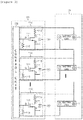
- FIG. 3 is a diagram illustrating an example of a particular configuration of the battery balancing apparatus according to the exemplary embodiment of the present invention.
- the battery balancing apparatus 100 may include a balancing unit 110, a control unit 120, and a self-discharging unit 130.
- the battery balancing apparatuses 100 illustrated in FIGS. 1 and 2 are the exemplary embodiment, and constituent elements thereof are not limited to the exemplary embodiment illustrated in FIGS. 2 and 3 , and may be added, changed, or deleted as necessary.
- the battery balancing apparatus 100 may be included in the battery 10 including battery cells 11, and the BMS 20, which calculates an SOC, an SOH, and a maximum input/output power allowance quantity of the battery cell 11 based on a voltage, a current, and a temperature of each of the battery cells 11, and controls a charge or a discharge of the battery cell 11 by using the calculated state information (the SOC, the SOH, and the maximum input/output power allowance quantity) of the battery cell 11.
- the balancing unit 110 may serve to balance a voltage charged in the battery cell 11 included in the battery 10. More particularly, when a voltage value of the battery cell 11 is equal to or larger than a predetermined second reference voltage value, the balancing unit 110 may perform passive balancing of discharging the battery cell 11. To this end, the balancing unit 110 may include a switching element 111 and a balancing resistor 112.
- the switching element 111 may be any one among a metal oxide silicon field effect transistor (MOS FET) device, an insulated gate bipolar transistor (IGBT) device, and a bipolar junction transistor (BJT) device.
- MOS FET metal oxide silicon field effect transistor
- IGBT insulated gate bipolar transistor
- BJT bipolar junction transistor
- the balancing unit 110 may further include a gate resistor 113 for adjusting a gate voltage of the MOS FET device, in addition to the balancing resistor 112.
- the balancing unit 110 in which the switching element 111 is the MOS FET device, will be described.
- the switching element 111 may include a drain terminal D, a gate terminal G, and a source terminal S, and the drain terminal D and the gate terminal G may be connected to the balancing resistor 112 and the gate resistor 113, respectively.
- the current flowing in the balancing resistor 112 may be a current output from the battery cell 11 in order to perform the balancing of the battery cell 11 according to the application of the voltage having the predetermined first reference voltage value or larger to the battery cell 11.
- the switching element 111 is electrically conducted and the current output from the battery cell 11 flows in the balancing resistor 112, so that the battery cell 11 is discharged, and thus, the voltage value of the battery cell 11, which is charged with the voltage having the predetermined first reference voltage value or larger, may be decreased.
- a resistance value of the gate resistor 113 may be changed.
- the control unit 120 may serve to control an operation of the balancing unit 110 in response to a voltage value of the battery cell 11.
- the control unit 120 may apply a gate voltage having the threshold voltage or larger of the switching element 111 to the gate terminal G and control an operation state of the switching element 111 to be on.
- the predetermined second reference voltage value may be a voltage value serving as a reference for determining whether to perform the balancing of the battery cell 11.
- control unit 120 allows the current to flow in the balancing resistor 112 connected with the drain terminal D of the switching element 111, thereby discharging the battery cell 11.
- control unit 120 may control an operation state of the switching element 111 to be off and may not discharge the battery cell 11.
- control unit 120 may be any one of a micro controller unit (MCU) and an application specific integrated circuit (ASIC).
- MCU micro controller unit
- ASIC application specific integrated circuit
- the switching element 111 may not be switched from off to on even though the voltage value of the battery cell 11 is equal to or larger than the predetermined second reference voltage value.
- the switching element 111 may not be switched from off to on even though the voltage value of the battery cell 11 is equal to or larger than the predetermined second reference voltage value.
- the voltage that is equal to or larger than the predetermined second reference voltage value is charged in the battery cell 11, so that imbalance is generated between the battery cells 11.
- the self-discharging unit 130 is connected to the switching element 111 in parallel, so that an inverse voltage of the voltage of the battery cell 11 is applied, and may serve to discharge the battery cell 11 according to whether the voltage of the battery cell 11 exceeds the predetermined first reference voltage value.
- the self-discharging unit 130 may discharge the battery cell 11 when the voltage value of the battery cell 11 exceeds the predetermined first reference voltage value.
- the self-discharging unit 130 may not discharge the battery cell 11.
- the predetermined first reference voltage value may be a voltage value larger than the predetermined second reference voltage value.
- the self-discharging unit 130 may be any one of a zener diode and a transient voltage suppression (TVS) diode, and when the self-discharging unit 130 is the zener diode, the predetermined first reference voltage value may be a breakdown voltage value of the zener diode.
- TVS transient voltage suppression
- the switching element 111 When the switching element 111 is not operated and is not switched on, and the battery cell 11 is not discharged even though the voltage that is equal to or larger than the predetermined second reference voltage value is charged in the battery cell 11, the voltage of the battery cell 11 may be charged with the predetermined first reference voltage value which exceeds the predetermined second reference voltage value.
- the voltage of the first reference voltage value exceeding the breakdown voltage value is applied to both ends of the self-discharging unit 130 that is the zener diode, and thus, the zener diode is electrically conducted and a current flows in the balancing resistor 112, thereby discharging the battery cell 11.
- the voltage of the battery cell 11 is decreased by the discharging of the battery cell 11, so that the voltage having the predetermined first reference voltage value or smaller may be charged in the battery cell 11.
- the voltage of the breakdown voltage value or smaller is applied to both ends of the self-discharging unit 130 that is the zener diode and the zener diode is turned off, so that the discharging of the battery cell 11 may be stopped.
- the battery balancing apparatus 100 even though the switching element 111 performing the balancing of the battery cell 11 and the control unit 120 controlling the switching element 11 are erroneously operated, when a voltage value of the battery cell 11 exceeds the predetermined first reference voltage value, the battery cell 11 is discharged through the self-discharging unit 130, thereby preventing the battery cell 11 from being overcharged.
- FIG. 4 is a flowchart for describing a battery balancing method according to an exemplary embodiment of the present invention.
- the BMS measures a voltage applied to a battery cell (S601), and the control unit controls an operation state of the switching element in response to the measured voltage of the battery cell to perform balancing of the battery cell.
- the control unit applies a gate voltage of a threshold voltage or larger of the switching element to a gate terminal and changes an operation state of the switching element to be on (S403). Accordingly, a current flows in the balancing resistor and the battery cell is discharged.
- the control unit does not change the operation state of the switching element and returns to the start.
- the control unit or the switching element is erroneously operated, when the battery cell is not balanced, that is, not discharged in operations S401 to S403, so that the voltage of the battery cell is increased to a predetermined second reference voltage value or more and exceeds the predetermined first reference voltage value (S404), the operation state of the self-discharging unit that is connected with the switching element in parallel is changed to be on (S405). Accordingly, a current flows in the balancing resistor, so that the battery cell is discharged (S406), and the voltage of the battery cell is decreased to be the predetermined first reference voltage value or smaller.
- the battery balancing method even though the switching element performing the balancing of the battery cell and the control unit controlling the switching element are erroneously operated, when a voltage value of the battery cell exceeds the predetermined first reference voltage value, the battery cell is discharged through the self-discharging unit, thereby preventing the battery cell from being overcharged.
Landscapes
- Engineering & Computer Science (AREA)
- Power Engineering (AREA)
- Life Sciences & Earth Sciences (AREA)
- Sustainable Development (AREA)
- Sustainable Energy (AREA)
- Transportation (AREA)
- Mechanical Engineering (AREA)
- Manufacturing & Machinery (AREA)
- Chemical & Material Sciences (AREA)
- Chemical Kinetics & Catalysis (AREA)
- Electrochemistry (AREA)
- General Chemical & Material Sciences (AREA)
- Microelectronics & Electronic Packaging (AREA)
- Secondary Cells (AREA)
- Charge And Discharge Circuits For Batteries Or The Like (AREA)
- Electric Propulsion And Braking For Vehicles (AREA)
Applications Claiming Priority (2)
| Application Number | Priority Date | Filing Date | Title |
|---|---|---|---|
| KR1020160097478A KR20180013574A (ko) | 2016-07-29 | 2016-07-29 | 배터리 밸런싱 장치 및 방법 |
| PCT/KR2017/004859 WO2018021664A1 (ko) | 2016-07-29 | 2017-05-11 | 배터리 밸런싱 장치 및 방법 |
Publications (3)
| Publication Number | Publication Date |
|---|---|
| EP3396809A1 true EP3396809A1 (de) | 2018-10-31 |
| EP3396809A4 EP3396809A4 (de) | 2019-04-17 |
| EP3396809B1 EP3396809B1 (de) | 2022-10-19 |
Family
ID=61017552
Family Applications (1)
| Application Number | Title | Priority Date | Filing Date |
|---|---|---|---|
| EP17834609.4A Active EP3396809B1 (de) | 2016-07-29 | 2017-05-11 | Batterieausgleichsvorrichtung und -verfahren |
Country Status (9)
| Country | Link |
|---|---|
| US (1) | US20190023146A1 (de) |
| EP (1) | EP3396809B1 (de) |
| JP (1) | JP6868037B2 (de) |
| KR (1) | KR20180013574A (de) |
| CN (1) | CN108604812A (de) |
| ES (1) | ES2933802T3 (de) |
| HU (1) | HUE060451T2 (de) |
| PL (1) | PL3396809T3 (de) |
| WO (1) | WO2018021664A1 (de) |
Families Citing this family (14)
| Publication number | Priority date | Publication date | Assignee | Title |
|---|---|---|---|---|
| KR102236384B1 (ko) | 2017-10-27 | 2021-04-05 | 주식회사 엘지화학 | 배터리 밸런싱을 위한 장치 및 그것을 포함하는 배터리팩 |
| US10608442B1 (en) * | 2018-09-24 | 2020-03-31 | Texas Instruments Incorporated | Adaptive cell-balancing |
| KR102443667B1 (ko) * | 2018-10-26 | 2022-09-14 | 주식회사 엘지에너지솔루션 | 밸런싱 장치, 및 그것을 포함하는 배터리 관리 시스템과 배터리팩 |
| US11374734B2 (en) * | 2019-01-04 | 2022-06-28 | Baidu Usa Llc | Method and system for key distribution and exchange for data processing accelerators |
| CN112236772B (zh) | 2019-01-04 | 2023-12-22 | 百度时代网络技术(北京)有限公司 | 用于管理数据处理加速器的内存的方法和系统 |
| US11799651B2 (en) | 2019-01-04 | 2023-10-24 | Baidu Usa Llc | Data processing accelerator having a security unit to provide root trust services |
| EP3794444A4 (de) | 2019-01-04 | 2022-01-12 | Baidu.com Times Technology (Beijing) Co., Ltd. | Verfahren und system zum schutz von durch datenverarbeitungsbeschleuniger verarbeiteten daten |
| EP3794763B1 (de) | 2019-01-04 | 2024-08-14 | Baidu.com Times Technology (Beijing) Co., Ltd. | Bestätigungsprotokoll zwischen einem hostsystem und einem datenverarbeitungsbeschleuniger |
| US11328075B2 (en) | 2019-01-04 | 2022-05-10 | Baidu Usa Llc | Method and system for providing secure communications between a host system and a data processing accelerator |
| EP3794477B1 (de) | 2019-01-04 | 2023-05-10 | Baidu.com Times Technology (Beijing) Co., Ltd. | Verfahren und system zur validierung von kernel-objekten, die von einem datenverarbeitungsbeschleuniger eines hostsystems ausgeführt werden |
| EP3811557B1 (de) | 2019-01-04 | 2026-02-11 | Baidu.com Times Technology (Beijing) Co., Ltd. | Verfahren und system zur ableitung eines sitzungsschlüssels zur sicherung eines informationsaustauschkanals zwischen einem host-system und einem datenverarbeitungsbeschleuniger |
| CN112334902B (zh) | 2019-01-04 | 2024-11-15 | 百度时代网络技术(北京)有限公司 | 建立主机系统与数据处理加速器之间的安全信息交换信道的方法 |
| WO2023167508A1 (ko) * | 2022-03-02 | 2023-09-07 | 주식회사 마루온 | 배터리 방전장치 및 그 방전방법 |
| KR20250046686A (ko) | 2023-09-27 | 2025-04-03 | 현대모비스 주식회사 | 셀 밸런싱 장치 |
Family Cites Families (17)
| Publication number | Priority date | Publication date | Assignee | Title |
|---|---|---|---|---|
| US6331763B1 (en) * | 1998-04-15 | 2001-12-18 | Tyco Electronics Corporation | Devices and methods for protection of rechargeable elements |
| JP2000184609A (ja) * | 1998-12-17 | 2000-06-30 | Japan Storage Battery Co Ltd | 群電池の容量平準化回路 |
| CA2406500C (en) * | 2001-10-01 | 2008-04-01 | Research In Motion Limited | An over-voltage protection circuit for use in a charging circuit |
| KR100908716B1 (ko) * | 2007-03-02 | 2009-07-22 | 삼성에스디아이 주식회사 | 배터리 관리 시스템 및 그의 구동 방법 |
| JP5423805B2 (ja) * | 2009-10-27 | 2014-02-19 | ミツミ電機株式会社 | 充放電制御回路、半導体集積回路、充放電制御方法及び充放電制御プログラム |
| JP2011188789A (ja) * | 2010-03-15 | 2011-09-29 | Yanmar Co Ltd | 電動乗用草刈機 |
| JP6229248B2 (ja) * | 2011-06-03 | 2017-11-15 | 株式会社Gsユアサ | 蓄電モジュールのセル監視装置、および断線検出方法 |
| CN102355015A (zh) * | 2011-09-07 | 2012-02-15 | 重庆长安汽车股份有限公司 | 一种电动汽车分布式电池管理系统 |
| FR2986383B1 (fr) * | 2012-02-01 | 2014-02-14 | Renault Sa | Equilibrage d'une batterie de stockage d'energie electrique a au moins deux branches paralleles |
| KR101165593B1 (ko) * | 2012-02-07 | 2012-07-23 | (주)이미지스테크놀로지 | 양방향 디씨-디씨 컨버터를 이용한 배터리 관리 시스템의 셀 밸런싱 회로 장치 |
| JP5660105B2 (ja) * | 2012-10-24 | 2015-01-28 | トヨタ自動車株式会社 | 蓄電システム |
| KR102044808B1 (ko) * | 2013-04-17 | 2019-11-15 | 엘지이노텍 주식회사 | 배터리 제어 시스템 및 그의 구동 방법 |
| US9531038B2 (en) * | 2013-07-31 | 2016-12-27 | Dell Products, Lp | System and method of cell block voltage analytics to improve balancing effectiveness and identify self-discharge rate |
| JP6056730B2 (ja) * | 2013-10-16 | 2017-01-11 | トヨタ自動車株式会社 | 蓄電システム |
| JP6107836B2 (ja) * | 2015-01-07 | 2017-04-05 | トヨタ自動車株式会社 | 電池監視装置 |
| JP2016134948A (ja) * | 2015-01-16 | 2016-07-25 | トヨタ自動車株式会社 | 電源システム |
| KR101619770B1 (ko) * | 2015-01-26 | 2016-05-11 | 주식회사 서울파워시스템 | 배터리 관리 시스템 |
-
2016
- 2016-07-29 KR KR1020160097478A patent/KR20180013574A/ko not_active Ceased
-
2017
- 2017-05-11 EP EP17834609.4A patent/EP3396809B1/de active Active
- 2017-05-11 JP JP2018555098A patent/JP6868037B2/ja active Active
- 2017-05-11 US US16/070,457 patent/US20190023146A1/en not_active Abandoned
- 2017-05-11 WO PCT/KR2017/004859 patent/WO2018021664A1/ko not_active Ceased
- 2017-05-11 ES ES17834609T patent/ES2933802T3/es active Active
- 2017-05-11 CN CN201780008517.7A patent/CN108604812A/zh active Pending
- 2017-05-11 PL PL17834609.4T patent/PL3396809T3/pl unknown
- 2017-05-11 HU HUE17834609A patent/HUE060451T2/hu unknown
Also Published As
| Publication number | Publication date |
|---|---|
| HUE060451T2 (hu) | 2023-03-28 |
| WO2018021664A1 (ko) | 2018-02-01 |
| ES2933802T3 (es) | 2023-02-14 |
| CN108604812A (zh) | 2018-09-28 |
| EP3396809B1 (de) | 2022-10-19 |
| JP6868037B2 (ja) | 2021-05-12 |
| US20190023146A1 (en) | 2019-01-24 |
| JP2019504612A (ja) | 2019-02-14 |
| EP3396809A4 (de) | 2019-04-17 |
| PL3396809T3 (pl) | 2023-03-13 |
| KR20180013574A (ko) | 2018-02-07 |
Similar Documents
| Publication | Publication Date | Title |
|---|---|---|
| EP3396809B1 (de) | Batterieausgleichsvorrichtung und -verfahren | |
| KR101680526B1 (ko) | 배터리 제어 장치 및 방법 | |
| US9954379B2 (en) | Apparatus, system, and method of preventing battery rack damage by measuring voltage | |
| CN107394834B (zh) | 电池装置 | |
| US9373973B2 (en) | Apparatus, system, and method of preventing battery rack damage by measuring current | |
| EP3261168B1 (de) | Symmetrierungsvorrichtung für eine batterie | |
| US10461546B2 (en) | System and method of managing battery by using balancing battery | |
| EP3339086A1 (de) | Kraftfahrzeug sowie lade- und entladesteuerungsschaltung dafür | |
| CN108780928B (zh) | 电池管理系统 | |
| US20230050979A1 (en) | Charging Management Apparatus, Charging Management Method, And Electric Vehicle | |
| CN110431723B (zh) | 电池装置、电池管理装置、电子设备、电动车辆、蓄电装置及电力系统 | |
| CN112119563A (zh) | 蓄电系统 | |
| US20200321664A1 (en) | Battery control method | |
| KR102225896B1 (ko) | 배터리 셀을 이용한 저전압 전원 공급 장치 및 방법 | |
| CN108352719B (zh) | 电源装置 | |
| EP3246718B1 (de) | Transformatorrelais und system zum messen von batteriespannung | |
| KR102096132B1 (ko) | 배터리 셀 밸런싱 장치 및 방법 | |
| KR20160049300A (ko) | 배터리 랙 간 전압 밸런싱 장치 및 방법 | |
| US12136839B2 (en) | Pre-charge circuit and battery system having the same | |
| JP2019198195A (ja) | 車載用リチウムイオンバッテリ制御装置 | |
| JP2022101801A (ja) | バッテリパックの制御システム | |
| US10850691B2 (en) | Management device and power supply system | |
| KR102141263B1 (ko) | 배터리 셀의 밸런싱 저항값 추정 장치 및 방법 | |
| CN107210613A (zh) | 本质安全的电池组电池的接通延迟 |
Legal Events
| Date | Code | Title | Description |
|---|---|---|---|
| STAA | Information on the status of an ep patent application or granted ep patent |
Free format text: STATUS: THE INTERNATIONAL PUBLICATION HAS BEEN MADE |
|
| PUAI | Public reference made under article 153(3) epc to a published international application that has entered the european phase |
Free format text: ORIGINAL CODE: 0009012 |
|
| STAA | Information on the status of an ep patent application or granted ep patent |
Free format text: STATUS: REQUEST FOR EXAMINATION WAS MADE |
|
| 17P | Request for examination filed |
Effective date: 20180726 |
|
| AK | Designated contracting states |
Kind code of ref document: A1 Designated state(s): AL AT BE BG CH CY CZ DE DK EE ES FI FR GB GR HR HU IE IS IT LI LT LU LV MC MK MT NL NO PL PT RO RS SE SI SK SM TR |
|
| AX | Request for extension of the european patent |
Extension state: BA ME |
|
| A4 | Supplementary search report drawn up and despatched |
Effective date: 20190319 |
|
| RIC1 | Information provided on ipc code assigned before grant |
Ipc: H01M 10/44 20060101ALI20190313BHEP Ipc: B60L 3/00 20190101ALI20190313BHEP Ipc: B60L 50/50 20190101ALI20190313BHEP Ipc: B60L 58/15 20190101ALI20190313BHEP Ipc: H01M 10/42 20060101ALI20190313BHEP Ipc: H02J 7/00 20060101AFI20190313BHEP Ipc: B60L 58/22 20190101ALI20190313BHEP |
|
| DAV | Request for validation of the european patent (deleted) | ||
| DAX | Request for extension of the european patent (deleted) | ||
| STAA | Information on the status of an ep patent application or granted ep patent |
Free format text: STATUS: EXAMINATION IS IN PROGRESS |
|
| 17Q | First examination report despatched |
Effective date: 20200507 |
|
| RAP1 | Party data changed (applicant data changed or rights of an application transferred) |
Owner name: LG ENERGY SOLUTION LTD. |
|
| RAP3 | Party data changed (applicant data changed or rights of an application transferred) |
Owner name: LG ENERGY SOLUTION, LTD. |
|
| GRAP | Despatch of communication of intention to grant a patent |
Free format text: ORIGINAL CODE: EPIDOSNIGR1 |
|
| STAA | Information on the status of an ep patent application or granted ep patent |
Free format text: STATUS: GRANT OF PATENT IS INTENDED |
|
| INTG | Intention to grant announced |
Effective date: 20220729 |
|
| GRAS | Grant fee paid |
Free format text: ORIGINAL CODE: EPIDOSNIGR3 |
|
| GRAA | (expected) grant |
Free format text: ORIGINAL CODE: 0009210 |
|
| STAA | Information on the status of an ep patent application or granted ep patent |
Free format text: STATUS: THE PATENT HAS BEEN GRANTED |
|
| AK | Designated contracting states |
Kind code of ref document: B1 Designated state(s): AL AT BE BG CH CY CZ DE DK EE ES FI FR GB GR HR HU IE IS IT LI LT LU LV MC MK MT NL NO PL PT RO RS SE SI SK SM TR |
|
| REG | Reference to a national code |
Ref country code: GB Ref legal event code: FG4D |
|
| REG | Reference to a national code |
Ref country code: CH Ref legal event code: EP |
|
| REG | Reference to a national code |
Ref country code: DE Ref legal event code: R096 Ref document number: 602017062854 Country of ref document: DE |
|
| REG | Reference to a national code |
Ref country code: IE Ref legal event code: FG4D |
|
| REG | Reference to a national code |
Ref country code: AT Ref legal event code: REF Ref document number: 1526171 Country of ref document: AT Kind code of ref document: T Effective date: 20221115 |
|
| REG | Reference to a national code |
Ref country code: SE Ref legal event code: TRGR |
|
| REG | Reference to a national code |
Ref country code: LT Ref legal event code: MG9D |
|
| REG | Reference to a national code |
Ref country code: ES Ref legal event code: FG2A Ref document number: 2933802 Country of ref document: ES Kind code of ref document: T3 Effective date: 20230214 |
|
| REG | Reference to a national code |
Ref country code: NL Ref legal event code: MP Effective date: 20221019 |
|
| REG | Reference to a national code |
Ref country code: AT Ref legal event code: MK05 Ref document number: 1526171 Country of ref document: AT Kind code of ref document: T Effective date: 20221019 |
|
| REG | Reference to a national code |
Ref country code: HU Ref legal event code: AG4A Ref document number: E060451 Country of ref document: HU |
|
| PG25 | Lapsed in a contracting state [announced via postgrant information from national office to epo] |
Ref country code: NL Free format text: LAPSE BECAUSE OF FAILURE TO SUBMIT A TRANSLATION OF THE DESCRIPTION OR TO PAY THE FEE WITHIN THE PRESCRIBED TIME-LIMIT Effective date: 20221019 |
|
| PG25 | Lapsed in a contracting state [announced via postgrant information from national office to epo] |
Ref country code: PT Free format text: LAPSE BECAUSE OF FAILURE TO SUBMIT A TRANSLATION OF THE DESCRIPTION OR TO PAY THE FEE WITHIN THE PRESCRIBED TIME-LIMIT Effective date: 20230220 Ref country code: NO Free format text: LAPSE BECAUSE OF FAILURE TO SUBMIT A TRANSLATION OF THE DESCRIPTION OR TO PAY THE FEE WITHIN THE PRESCRIBED TIME-LIMIT Effective date: 20230119 Ref country code: LT Free format text: LAPSE BECAUSE OF FAILURE TO SUBMIT A TRANSLATION OF THE DESCRIPTION OR TO PAY THE FEE WITHIN THE PRESCRIBED TIME-LIMIT Effective date: 20221019 Ref country code: FI Free format text: LAPSE BECAUSE OF FAILURE TO SUBMIT A TRANSLATION OF THE DESCRIPTION OR TO PAY THE FEE WITHIN THE PRESCRIBED TIME-LIMIT Effective date: 20221019 Ref country code: AT Free format text: LAPSE BECAUSE OF FAILURE TO SUBMIT A TRANSLATION OF THE DESCRIPTION OR TO PAY THE FEE WITHIN THE PRESCRIBED TIME-LIMIT Effective date: 20221019 |
|
| PG25 | Lapsed in a contracting state [announced via postgrant information from national office to epo] |
Ref country code: RS Free format text: LAPSE BECAUSE OF FAILURE TO SUBMIT A TRANSLATION OF THE DESCRIPTION OR TO PAY THE FEE WITHIN THE PRESCRIBED TIME-LIMIT Effective date: 20221019 Ref country code: LV Free format text: LAPSE BECAUSE OF FAILURE TO SUBMIT A TRANSLATION OF THE DESCRIPTION OR TO PAY THE FEE WITHIN THE PRESCRIBED TIME-LIMIT Effective date: 20221019 Ref country code: IS Free format text: LAPSE BECAUSE OF FAILURE TO SUBMIT A TRANSLATION OF THE DESCRIPTION OR TO PAY THE FEE WITHIN THE PRESCRIBED TIME-LIMIT Effective date: 20230219 Ref country code: HR Free format text: LAPSE BECAUSE OF FAILURE TO SUBMIT A TRANSLATION OF THE DESCRIPTION OR TO PAY THE FEE WITHIN THE PRESCRIBED TIME-LIMIT Effective date: 20221019 Ref country code: GR Free format text: LAPSE BECAUSE OF FAILURE TO SUBMIT A TRANSLATION OF THE DESCRIPTION OR TO PAY THE FEE WITHIN THE PRESCRIBED TIME-LIMIT Effective date: 20230120 |
|
| P01 | Opt-out of the competence of the unified patent court (upc) registered |
Effective date: 20230512 |
|
| REG | Reference to a national code |
Ref country code: DE Ref legal event code: R097 Ref document number: 602017062854 Country of ref document: DE |
|
| PG25 | Lapsed in a contracting state [announced via postgrant information from national office to epo] |
Ref country code: SM Free format text: LAPSE BECAUSE OF FAILURE TO SUBMIT A TRANSLATION OF THE DESCRIPTION OR TO PAY THE FEE WITHIN THE PRESCRIBED TIME-LIMIT Effective date: 20221019 Ref country code: RO Free format text: LAPSE BECAUSE OF FAILURE TO SUBMIT A TRANSLATION OF THE DESCRIPTION OR TO PAY THE FEE WITHIN THE PRESCRIBED TIME-LIMIT Effective date: 20221019 Ref country code: EE Free format text: LAPSE BECAUSE OF FAILURE TO SUBMIT A TRANSLATION OF THE DESCRIPTION OR TO PAY THE FEE WITHIN THE PRESCRIBED TIME-LIMIT Effective date: 20221019 Ref country code: DK Free format text: LAPSE BECAUSE OF FAILURE TO SUBMIT A TRANSLATION OF THE DESCRIPTION OR TO PAY THE FEE WITHIN THE PRESCRIBED TIME-LIMIT Effective date: 20221019 Ref country code: CZ Free format text: LAPSE BECAUSE OF FAILURE TO SUBMIT A TRANSLATION OF THE DESCRIPTION OR TO PAY THE FEE WITHIN THE PRESCRIBED TIME-LIMIT Effective date: 20221019 |
|
| PLBE | No opposition filed within time limit |
Free format text: ORIGINAL CODE: 0009261 |
|
| STAA | Information on the status of an ep patent application or granted ep patent |
Free format text: STATUS: NO OPPOSITION FILED WITHIN TIME LIMIT |
|
| PG25 | Lapsed in a contracting state [announced via postgrant information from national office to epo] |
Ref country code: SK Free format text: LAPSE BECAUSE OF FAILURE TO SUBMIT A TRANSLATION OF THE DESCRIPTION OR TO PAY THE FEE WITHIN THE PRESCRIBED TIME-LIMIT Effective date: 20221019 Ref country code: AL Free format text: LAPSE BECAUSE OF FAILURE TO SUBMIT A TRANSLATION OF THE DESCRIPTION OR TO PAY THE FEE WITHIN THE PRESCRIBED TIME-LIMIT Effective date: 20221019 |
|
| 26N | No opposition filed |
Effective date: 20230720 |
|
| PG25 | Lapsed in a contracting state [announced via postgrant information from national office to epo] |
Ref country code: SI Free format text: LAPSE BECAUSE OF FAILURE TO SUBMIT A TRANSLATION OF THE DESCRIPTION OR TO PAY THE FEE WITHIN THE PRESCRIBED TIME-LIMIT Effective date: 20221019 |
|
| REG | Reference to a national code |
Ref country code: CH Ref legal event code: PL |
|
| PG25 | Lapsed in a contracting state [announced via postgrant information from national office to epo] |
Ref country code: MC Free format text: LAPSE BECAUSE OF FAILURE TO SUBMIT A TRANSLATION OF THE DESCRIPTION OR TO PAY THE FEE WITHIN THE PRESCRIBED TIME-LIMIT Effective date: 20221019 |
|
| REG | Reference to a national code |
Ref country code: BE Ref legal event code: MM Effective date: 20230531 |
|
| PG25 | Lapsed in a contracting state [announced via postgrant information from national office to epo] |
Ref country code: MC Free format text: LAPSE BECAUSE OF FAILURE TO SUBMIT A TRANSLATION OF THE DESCRIPTION OR TO PAY THE FEE WITHIN THE PRESCRIBED TIME-LIMIT Effective date: 20221019 Ref country code: LU Free format text: LAPSE BECAUSE OF NON-PAYMENT OF DUE FEES Effective date: 20230511 Ref country code: LI Free format text: LAPSE BECAUSE OF NON-PAYMENT OF DUE FEES Effective date: 20230531 Ref country code: CH Free format text: LAPSE BECAUSE OF NON-PAYMENT OF DUE FEES Effective date: 20230531 |
|
| REG | Reference to a national code |
Ref country code: IE Ref legal event code: MM4A |
|
| PG25 | Lapsed in a contracting state [announced via postgrant information from national office to epo] |
Ref country code: IE Free format text: LAPSE BECAUSE OF NON-PAYMENT OF DUE FEES Effective date: 20230511 |
|
| PG25 | Lapsed in a contracting state [announced via postgrant information from national office to epo] |
Ref country code: IE Free format text: LAPSE BECAUSE OF NON-PAYMENT OF DUE FEES Effective date: 20230511 |
|
| PG25 | Lapsed in a contracting state [announced via postgrant information from national office to epo] |
Ref country code: IT Free format text: LAPSE BECAUSE OF FAILURE TO SUBMIT A TRANSLATION OF THE DESCRIPTION OR TO PAY THE FEE WITHIN THE PRESCRIBED TIME-LIMIT Effective date: 20221019 Ref country code: BE Free format text: LAPSE BECAUSE OF NON-PAYMENT OF DUE FEES Effective date: 20230531 |
|
| PG25 | Lapsed in a contracting state [announced via postgrant information from national office to epo] |
Ref country code: BG Free format text: LAPSE BECAUSE OF FAILURE TO SUBMIT A TRANSLATION OF THE DESCRIPTION OR TO PAY THE FEE WITHIN THE PRESCRIBED TIME-LIMIT Effective date: 20221019 |
|
| PG25 | Lapsed in a contracting state [announced via postgrant information from national office to epo] |
Ref country code: BG Free format text: LAPSE BECAUSE OF FAILURE TO SUBMIT A TRANSLATION OF THE DESCRIPTION OR TO PAY THE FEE WITHIN THE PRESCRIBED TIME-LIMIT Effective date: 20221019 |
|
| PGFP | Annual fee paid to national office [announced via postgrant information from national office to epo] |
Ref country code: DE Payment date: 20250422 Year of fee payment: 9 Ref country code: PL Payment date: 20250423 Year of fee payment: 9 |
|
| PGFP | Annual fee paid to national office [announced via postgrant information from national office to epo] |
Ref country code: ES Payment date: 20250613 Year of fee payment: 9 |
|
| PGFP | Annual fee paid to national office [announced via postgrant information from national office to epo] |
Ref country code: HU Payment date: 20250526 Year of fee payment: 9 |
|
| PGFP | Annual fee paid to national office [announced via postgrant information from national office to epo] |
Ref country code: FR Payment date: 20250422 Year of fee payment: 9 |
|
| PG25 | Lapsed in a contracting state [announced via postgrant information from national office to epo] |
Ref country code: CY Free format text: LAPSE BECAUSE OF FAILURE TO SUBMIT A TRANSLATION OF THE DESCRIPTION OR TO PAY THE FEE WITHIN THE PRESCRIBED TIME-LIMIT; INVALID AB INITIO Effective date: 20170511 |
|
| PGFP | Annual fee paid to national office [announced via postgrant information from national office to epo] |
Ref country code: SE Payment date: 20250422 Year of fee payment: 9 |
|
| PG25 | Lapsed in a contracting state [announced via postgrant information from national office to epo] |
Ref country code: TR Free format text: LAPSE BECAUSE OF FAILURE TO SUBMIT A TRANSLATION OF THE DESCRIPTION OR TO PAY THE FEE WITHIN THE PRESCRIBED TIME-LIMIT Effective date: 20221019 |
|
| PGFP | Annual fee paid to national office [announced via postgrant information from national office to epo] |
Ref country code: GB Payment date: 20260324 Year of fee payment: 10 |