EP3397552B1 - Aéronef multirotor - Google Patents
Aéronef multirotor Download PDFInfo
- Publication number
- EP3397552B1 EP3397552B1 EP16888622.4A EP16888622A EP3397552B1 EP 3397552 B1 EP3397552 B1 EP 3397552B1 EP 16888622 A EP16888622 A EP 16888622A EP 3397552 B1 EP3397552 B1 EP 3397552B1
- Authority
- EP
- European Patent Office
- Prior art keywords
- actuator
- arms
- lateral shaft
- aircraft
- multirotor aircraft
- Prior art date
- Legal status (The legal status is an assumption and is not a legal conclusion. Google has not performed a legal analysis and makes no representation as to the accuracy of the status listed.)
- Active
Links
Images


Classifications
-
- B—PERFORMING OPERATIONS; TRANSPORTING
- B64—AIRCRAFT; AVIATION; COSMONAUTICS
- B64U—UNMANNED AERIAL VEHICLES [UAV]; EQUIPMENT THEREFOR
- B64U20/00—Constructional aspects of UAVs
- B64U20/70—Constructional aspects of the UAV body
-
- B—PERFORMING OPERATIONS; TRANSPORTING
- B64—AIRCRAFT; AVIATION; COSMONAUTICS
- B64U—UNMANNED AERIAL VEHICLES [UAV]; EQUIPMENT THEREFOR
- B64U50/00—Propulsion; Power supply
- B64U50/10—Propulsion
- B64U50/19—Propulsion using electrically powered motors
-
- G—PHYSICS
- G05—CONTROLLING; REGULATING
- G05D—SYSTEMS FOR CONTROLLING OR REGULATING NON-ELECTRIC VARIABLES
- G05D1/00—Control of position, course, altitude or attitude of land, water, air or space vehicles, e.g. using automatic pilots
- G05D1/0011—Control of position, course, altitude or attitude of land, water, air or space vehicles, e.g. using automatic pilots associated with a remote control arrangement
- G05D1/0038—Control of position, course, altitude or attitude of land, water, air or space vehicles, e.g. using automatic pilots associated with a remote control arrangement by providing the operator with simple or augmented images from one or more cameras located onboard the vehicle, e.g. tele-operation
-
- G—PHYSICS
- G05—CONTROLLING; REGULATING
- G05D—SYSTEMS FOR CONTROLLING OR REGULATING NON-ELECTRIC VARIABLES
- G05D1/00—Control of position, course, altitude or attitude of land, water, air or space vehicles, e.g. using automatic pilots
- G05D1/0094—Control of position, course, altitude or attitude of land, water, air or space vehicles, e.g. using automatic pilots involving pointing a payload, e.g. camera, weapon, sensor, towards a fixed or moving target
-
- G—PHYSICS
- G05—CONTROLLING; REGULATING
- G05D—SYSTEMS FOR CONTROLLING OR REGULATING NON-ELECTRIC VARIABLES
- G05D1/00—Control of position, course, altitude or attitude of land, water, air or space vehicles, e.g. using automatic pilots
- G05D1/08—Control of attitude, i.e. control of roll, pitch, or yaw
- G05D1/0808—Control of attitude, i.e. control of roll, pitch, or yaw specially adapted for aircraft
-
- B—PERFORMING OPERATIONS; TRANSPORTING
- B64—AIRCRAFT; AVIATION; COSMONAUTICS
- B64U—UNMANNED AERIAL VEHICLES [UAV]; EQUIPMENT THEREFOR
- B64U10/00—Type of UAV
- B64U10/10—Rotorcrafts
- B64U10/13—Flying platforms
- B64U10/14—Flying platforms with four distinct rotor axes, e.g. quadcopters
-
- B—PERFORMING OPERATIONS; TRANSPORTING
- B64—AIRCRAFT; AVIATION; COSMONAUTICS
- B64U—UNMANNED AERIAL VEHICLES [UAV]; EQUIPMENT THEREFOR
- B64U2101/00—UAVs specially adapted for particular uses or applications
- B64U2101/30—UAVs specially adapted for particular uses or applications for imaging, photography or videography
-
- B—PERFORMING OPERATIONS; TRANSPORTING
- B64—AIRCRAFT; AVIATION; COSMONAUTICS
- B64U—UNMANNED AERIAL VEHICLES [UAV]; EQUIPMENT THEREFOR
- B64U2201/00—UAVs characterised by their flight controls
- B64U2201/20—Remote controls
-
- B—PERFORMING OPERATIONS; TRANSPORTING
- B64—AIRCRAFT; AVIATION; COSMONAUTICS
- B64U—UNMANNED AERIAL VEHICLES [UAV]; EQUIPMENT THEREFOR
- B64U30/00—Means for producing lift; Empennages; Arrangements thereof
- B64U30/20—Rotors; Rotor supports
-
- B—PERFORMING OPERATIONS; TRANSPORTING
- B64—AIRCRAFT; AVIATION; COSMONAUTICS
- B64U—UNMANNED AERIAL VEHICLES [UAV]; EQUIPMENT THEREFOR
- B64U30/00—Means for producing lift; Empennages; Arrangements thereof
- B64U30/20—Rotors; Rotor supports
- B64U30/29—Constructional aspects of rotors or rotor supports; Arrangements thereof
- B64U30/296—Rotors with variable spatial positions relative to the UAV body
- B64U30/297—Tilting rotors
Definitions
- the present invention relates generally to unmanned aerial vehicle, and in particular to a multirotor aircraft.
- Multirotor aircraft designed for first person view (FPV) piloting usually employs an upturned fixed-angle camera as a compromise between forward and hover flight. It aims to the ground in fast forward-flight and to the sky in horizontal hover flight. In addition, the high pitch angle in forward flight leads to increased aerodynamic drag of the multirotor body.
- FV first person view
- US 2015021429 A1 discloses a remote-controlled aerial device platform, where the remote-controlled aerial device platform includes a body and a bridge.
- the body and the bridge are connected to one another via a central module, wherein the connection uses a gimbal support in order to allow as many degrees of freedom in the movement of the body relative to the bridge as possible.
- the central module 40 here has compensation elements which are here designed as servomotors.
- the body further comprises four arms that are curved inward.
- DE 102008025607 A1 discloses an aircraft, where the aircraft comprises four arms and four rotors disposed on the ends of the four arms respectively.
- the four arms are connected to a shaft by using external controllable axial rotation mechanisms (In a fastening means).
- the arms are straight.
- US 4678141 A discloses an VTOL aircraft, where the aircraft comprises a carrier and two engines disposed two ends of the carrier respectively. Engines are capable of being pivoted between a first position in which they provide substantially vertical thrust; and a second position in which the thrust provided is substantially horizontal.
- US 2011001001 A1 discloses a VTOL flying-wing aircraft, where the aircraft comprises a wing-structure that carries four thrust-vectoring propulsion units .
- the propulsion units are carried fore and aft respectively of a strake.
- the propulsion units are correspondingly carried fore and aft of a strake.
- the propulsion units are rotatably mounted on the strakes to enable the thrust each produces to be vectored to the extend necessary.
- a multirotor aircraft and a method for controlling the multirotor aircraft are provided, to obtain a more speed-independent and balanced camera view in terms of ground/sky and to reduce the aerodynamic drag in forward flight at the same time.
- a multirotor aircraft comprises:
- the servo mechanism comprises a second actuator, two gears and a rotary position sensor, the second actuator being coupled with the lateral shaft of the H-shaped frame by the gears and the rotary position sensor being configured to sense the rotation of the second actuator.
- the two gears comprises a first gear mounted on a shaft of the second actuator and a second gear mounted on the lateral shaft,, and the first gear being coupled with the second gear.
- the two arms connected with one end of the lateral shaft are integrally manufactured as one piece, and the other two arms connected to the other end of the lateral shaft are manufactured as one piece.
- the four arms are fixedly or removably coupled with the lateral shaft of the H-shaped frame.
- the two bearing comprise sliding bearings or rolling bearings.
- the second actuator comprises electric motor, mechanical actuator, hydraulic actuator or pneumatic actuator.
- Multirotor aircrafts accelerate and fly forward by tilting their propeller plane to the desired direction.
- a fixed-angle camera therefore aims to the ground in fast forward-flight with negative pitch angles and more to the sky in horizontal hover flight.
- the high pitch angle leads to increased aerodynamic drag of the multirotor body.
- the first approach creates a constant offset angle between the propeller plane and the camera axis in order to find a compromise between hover flight and forward flight. In its most simple and widespread form this is achieved by an upturned, fixed-angle camera mount.
- the second approach (Tilt Racing Drone, OFM SWIFT TR260) employs servo-controlled tilting motor arms in order to adjust the camera-propeller angle dynamically.
- the front and back motor arm of the H shaped frame is rotated synchronously in order to tilt the rotor plane without tilting the multirotor's body.
- the first approach (fixed camera-propeller angle) has the disadvantage of only partial compensation of pitch angle in forward flight and over compensation in hover flight which makes take-off and landing harder due to limited sight. Additionally, the body is in general not properly aligned with the flight direction, thus producing additional drag. For high camera tilt-angles, it becomes obvious and non-intuitive, that the pilot's rate commands are not aligned with the camera frame, but stay in the body-fixed frame.
- the second approach has drawbacks in two aspects.
- the overall system performance degrades at high tilt angles due to the propeller downwash hitting the rear propellers and due to the reduced lever arm between the motor axes.
- the multirotor aircraft and the method for controlling an aircraft provided by the present disclosure aim to obtain a more speed-independent and balanced camera view in terms of ground/sky and to reduce the aerodynamic drag in forward flight at the same time.
- the terms 'upper', 'lower', 'vertical', 'horizontal' and other similar position-indicating terms are used with reference to the multirotor aircraft in its normal operation mode, and should not be considered limiting.
- FIG. 1 illustrates an isometric view of a multirotor aircraft in accordance with an embodiment of the present invention.
- the multirotor aircraft 10 comprises a body 12 and a frame 14.
- the frame 14 has a lateral shaft 141, and the body 12 and the lateral shaft 141 of the frame 14 may be connected by a bearing, so that the frame 14 can rotate around the lateral shaft 141 with regard to the body 12.
- the frame 14 has rotated a certain angle around the lateral shaft 141 with regard to the body 12.
- a servo mechanism 121 may be mounted on the body 12, for controlling the rotation of the lateral shaft 141, so as to control the angle between the body 12 and the frame 14.
- an actuator assembly 18 is positioned on each arm of the H-shaped frame 14.
- the actuator assembly 18 comprises an actuator 181 and a propeller 182 coupled to the actuator 181.
- the actuator 181 may comprise electric motor, mechanical actuator, hydraulic actuator, pneumatic actuator, or the like. Electric motors may include magnetic, electrostatic or piezoelectric motors.
- the actuator includes a brushless DC electric motor.
- the actuator assembly 18 may be fixedly or removably coupled to each arm of the H-shaped frame 14.
- the body 12 may be mounted with one or more electrical component adapted to control various aspects of the operation of the multirotor aircraft 10.
- the term 'electrical component' refers to any component that provides, uses or transmits electricity.
- Such electrical components can include an energy source (e.g., battery), flight control or navigation module, GPS module (e.g., GPS receiver or transceivers), inertial measurement unit (IMU) module, communication module (e.g., wireless transceiver), electronic speed control (ESC) module adapted to control an actuator (e.g., electric motor), actuator(s) such as an electric motor used to actuate a propeller of the multirotor aircraft, electrical wirings and connectors, and the like.
- an energy source e.g., battery
- GPS module e.g., GPS receiver or transceivers
- IMU inertial measurement unit
- communication module e.g., wireless transceiver
- ESC electronic speed control
- an actuator e.g., electric motor
- actuator(s) such
- some of the electrical components may be located on an integrated electrical unit such as a circuit board o module. In some embodiments, some of the electrical components may be located on one or more circuit modules.
- Each circuit module can include one or more electrical components.
- the circuit module can include the flight control module that includes one or more processors (such as implemented by a field-programmable gate array (FPGA)) for controlling key operation of the multirotor aircraft.
- the same or a different circuit module can also include an IMU module for measuring the velocity, orientation and gravitational forces of the multirotor aircraft.
- the IMU module can include one or more accelerometers and/or gyroscopes.
- the same or a different circuit module can also include a communication module for remotely communicating with a remote control device.
- the communication module can include a wireless (e.g., radio) transceiver.
- the communication module can be provided with button or buttons and corresponding indicator light that is spaced apart from the buttons.
- the buttons and the indicator light may be used for facilitating communication between the multirotor aircraft and a remote control device.
- the buttons may be used to adjust the frequency channel used by the multirotor aircraft and the indicator light can be used to indicate the success and/or failure of the establishment of a communication channel between the multirotor aircraft and the remote control device.
- the fight control module is typically a key component or 'brain' of a multirotor aircraft.
- the flight control module can be configured to estimate the current velocity, orientation and/or position of the multirotor aircraft based on data obtained from visual sensors (e.g., cameras), IMU, GPS receiver and/or other sensors, perform path planning, provide control signals to actuators to implement navigational control and the like.
- the flight control module can be configured to issue control signals to adjust the state of the multirotor aircraft based on remotely received control signals.
- the body 12 has a rectangular shape, and the head of the body may be curved to facilitate high speed flight.
- the shape of the body 12 may be different from that of FIG.1 , for example, cone, cylinder etc.
- the body 12 is mounted with a first person view camera, for first person view piloting.
- the first person view camera may be positioned in the head of the body.
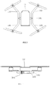
- FIG. 3 illustrated a top view of the multirotor aircraft of the FIG.1 , in accordance with the present invention.
- the frame 14 comprises four arms 142-145 and a lateral shaft 141, wherein two arms 142, 143 are connected to one end of the lateral shaft 141, and the other two arms 144, 145 are connected to the other end of the lateral shaft 141, and the four arms may be within the same plane.
- the two arms connected to either end of the lateral shaft may be symmetric with each other.
- the two arms 142, 143 connected to one end of the lateral shaft and the other two arms 144, 145 connected to the other end of the lateral shaft may be symmetric with respect to the central vertical line of the lateral shaft 141.
- the four arms 142-145 and lateral shaft 141 of the frame form a H-shaped frame.
- the term 'H-shaped frame' does no necessarily means strict H-shaped frame, but can also mean similar H-shaped frame as illustrated in FIG.3 .
- the four arms 142-145 of the H-shaped frame 14 are bended away from the body 12, so as to avoid the collision of the propellers on different arms in the case of a short lateral shaft.
- the four arms of the H-shaped frame 14 may have a shape different from the shape as shown in FIG.3 .
- the four arms may be straight, or may be bended toward the body, or may be any other shapes.
- each arm of the H-shaped frame 14 may be removably coupled to the lateral shaft 141.
- each arm may be removably coupled to the lateral shaft via fasteners such as screw, bolt, buckle, clamp, clasp, latch, hook, nail, pin, strap, cable, or the like.
- fasteners such as screw, bolt, buckle, clamp, clasp, latch, hook, nail, pin, strap, cable, or the like.
- each arm may be decoupled from the lateral shaft.
- each arm and the lateral shaft of the H-shaped frame may be welded or otherwise permanently held together.
- any individual or combination of the components that form the H-shaped frame 14 can be manufactured using any suitable technique such injection molding, additive manufacturing (3-D printing) techniques, or the like.
- each arm 142-145 and the lateral shaft 141 of the H-shaped frame 14 can be manufactured individually and welded, fastened or otherwise combined to form the H-shaped frame.
- the two arms 142-143 connected to one end of the lateral shaft can be integrally manufactured as one piece, and the other two arms 144-145 connected to the other end of the lateral shaft can be integrally manufactured as one piece. Then the two integrally manufactured pieces and the lateral shaft 141 can be combined (via welding, fastener, etc.) to from the H-shaped frame 14.
- the H-shaped frame 14 can be integrally manufactured, for example, using injection molding or additive manufacturing techniques.
- FIG.4 illustrated a back view of the multirotor aircraft of FIG.1 , in accordance with an embodiment of the present invention.
- the lateral shaft 141 can be connected with the body 12 by a bearing.
- two bearings 161-162 are positioned underneath the body 12, and the lateral shaft 141 of the H-shaped frame 14 goes through the two bearings 161-162, so that the H-shaped frame 14 rotates around the lateral shaft 141 with respect to the body 12.
- the two bearings 161-162 may be positioned at other places of the body, for example, may be positioned on the top of the body, or may be positioned on both sides of the body.
- the bearing can comprise a sliding bearing or a rolling bearing.
- FIG.5 illustrates a side view of the multirotor aircraft of FIG.1 , in accordance with an embodiment of the present invention.
- the body 12 is mounted with a servo mechanism 121.
- the servo mechanism 121 may comprise a second actuator, a gear and a rotary position sensor.
- the actuator may be coupled to the lateral shaft of the H-shaped frame by the gearing, so as to drive the later shaft of the H-shaped frame to rotate.
- one gear 1211 may be positioned on the shaft of the actuator, and another gear 1212 may be positioned on the lateral shaft 141 of the H-shaped frame, these two gears may be coupled with each other, so that the actuator may drive the gear on its shaft, which drives the gear on the lateral shaft, and as a result drives the lateral shaft to rotate.
- the two gears may be coupled to the shaft of the actuator and the lateral shaft of the H-shaped frame respectively by a spline or a flat key.
- one gear may be connected to the shaft of the actuator by a spline or a flat key
- the lateral shaft may be manufactured as a gear shaft
- the gear may be coupled with the gear shaft, so that the actuator can drive the gear shaft to rotate.
- rotary position sensor may sense the rotation of the actuator, and determine the angle between the boy and the H-shaped frame on the basis of the quantity of the rotation.
- the actuator may comprise electric motor, mechanical actuator, hydraulic actuator, pneumatic actuator, or the like. Electric motors may include magnetic, electrostatic or piezoelectric motors.
- the multirotor aircraft provided by embodiments of the present invention can solve the aforementioned problems.
- the camera view and the aerodynamic drag of the main body are optimized by aligning the body including the camera with the direction of flight. This is achieved by a two-piece construction with a dynamically controlled angle between the body and the frame with actuators and propellers. This way, the body can be operated at its lowest coefficient of drag without introducing interference between the front and rear propellers. Due to the fixed relative actuator angles and positions, the propellers still breathe laminar air and are not affected by the downwash of the front propellers.
- a method for controlling an aircraft may comprise a beginner friendly mode and an advanced mode.
- a beginner friendly mode In the beginner friendly mode, horizon is kept in the camera view of the aircraft.
- a control command is generated on the basis of the aircraft's camera aligned axis.
- the beginner friendly mode makes the FPV not only fun but also easy to fly.
- the advanced mode makes the user have an intuitive visual feedback of his/her commands.
- the generation of a control command on the basis of the aircraft's camera aligned axis may be implemented by the following procedures: obtaining the angle between the camera and the body as well as the attitude of the aircraft; determining the camera aligned axis according to the obtained angle and attitude; and generating a control command based on the determined camera aligned axis.
- the control command may comprise rate command.
- the aircraft may have a fixed body, tilting camera configuration.
- the aircraft may be the aforementioned multirotor aircraft with an upturned fixed-angle camera.
- the method may comprise: in the beginner friendly mode, keeping horizon within the camera view of the aircraft, by controlling each rotor's rotating speed.
- the above procedure may be implemented by the following steps: obtaining images taken by the camera; determining whether horizon is approaching an edge of the camera view according to the obtained images; if so, determining the direction in which horizon is approaching the edge; adjusting each rotor's rotating speed according to the reverse direction of the determined direction, in order to avoid horizon from leaving the camera view. For example, when it is determined that horizon is approaching the lower edge of the camera view according to the images taken by the camera, implying that the aircraft is flying upward with a high pitch angle, each rotor's rotating speed need to be controlled in order to reduce the pitch angle of the aircraft, so that horizon will not go across the lower edge of the camera.
- each rotor's speed need to be controlled in order to increase the pitch angle, so that horizon will not go across the upper edge of the camera view.
- the above procedure may be implemented by the following steps: obtaining the biggest pitch angle and the smallest pitch angle which make horizon within the camera view, according to the angle between the camera and the body as well as camera's view angle; obtaining the current pitch angle of the aircraft; if the current pitch angle of the aircraft is bigger than the biggest pitch angle, then controlling the speed of each rotor of the aircraft in order to reduce the pitch angle of the aircraft; if the current pitch angle of the aircraft is smaller than the smallest pitch angle, then controlling the speed of each rotor of the aircraft in order to increase the pitch angle of the aircraft.
- camera's view angle may be 60 degree, and the angle between the camera and the body is 10 degree, so the biggest pitch angle is 20 degree, and the smallest pitch angle is -40 degree.
- the speed of each rotor of the aircraft need to be controlled in order to reduce the pitch angle of the aircraft, however, if the current pitch angle is smaller than -40 degree, then the speed of each rotor of the aircraft need to be controlled in order to increase the pitch angle of the aircraft.
- the aircraft may be the multirotor aircraft according to embodiments of the present invention.
- the additional degree of freedom provided by the tilting mechanism may be used to control the multirotor aircraft.
- horizon may be kept within the camera view by controlling the angle between the body and the H-shaped frame of the multirotor aircraft utilizinging the servo mechanism.
- a normal multirotor aircraft speeds up the back rotors and slows down the front rotors, so that the body is tilted forward and the forward force is generated.
- the angle between the body and the H-shaped frame may be made larger by the servo mechanism, so that the rotors on the H-shaped frame may tilt forward and thus generate forward force. Therefore, forward flight can be realized while the alignment of the body and the flight direction is maintained, and as a result, horizon is kept within the camera view.
- the step of obtaining the attitude of the aircraft may be implemented by the following steps: obtaining the aerodynamic velocity vector of the aircraft and the angle between the body and H-shaped frame of the aircraft; and obtaining the attitude of the aircraft on the basis of the aerodynamic velocity vector and the angle between the body and the H-shaped frame.
- the angle between the body and the H-shaped frame may be obtained by the rotary position sensor of the servo mechanism of the multirotor aircraft.
- the method may further comprise: in the advanced mode, controlling the servo mechanism to keep the angle between the body and the H-shaped of the multirotor aircraft unchanged during the hover to cruise flight transition. Specifically, in the advanced mode, the actuator of the servo mechanism is kept still to keep the angle between the body and the H-shaped frame unchanged during the hover to cruise flight transition. Thus, intuitive visual feedback of the attitude may be provided to the user.
- the method may further comprise: in the advanced mode, receiving angle adjustment command from the user, and adjusting the angle between the body and the H-shaped frame of the multirotor by controlling the servo mechanism. In this way, the automatic angle compensation can be individually adjusted by the user.
- the multirotor aircraft in accordance with embodiments of the present invention may be used as FPV race multirotor for high speed flight with improved aerodynamic efficiency in cruise flight.
- the additional degree of freedom provided by the tilting mechanism gives a more intuitive camera view to the user.
- the multirotor aircraft can also be used as normal camera drone with 360 degree camera view utilizing the tilting degree of freedom of the camera.
Landscapes
- Engineering & Computer Science (AREA)
- Remote Sensing (AREA)
- Aviation & Aerospace Engineering (AREA)
- Radar, Positioning & Navigation (AREA)
- Chemical & Material Sciences (AREA)
- Combustion & Propulsion (AREA)
- Physics & Mathematics (AREA)
- General Physics & Mathematics (AREA)
- Automation & Control Theory (AREA)
- Mechanical Engineering (AREA)
- Studio Devices (AREA)
Claims (7)
- Aéronef multirotor (10), comprenant :un fuselage (12), le fuselage (10) étant monté avec deux paliers (161, 162) ;un cadre en forme de H (14), comprenant un arbre latéral (141) raccordé avec le fuselage (12) par les deux paliers (161, 162) et quatre bras (142, 143, 144, 145), deux bras (142, 143) étant raccordés à une extrémité de l'arbre latéral (141) et les deux autres bras (144, 145) étant raccordés à l'autre extrémité de l'arbre latéral (141);quatre ensembles actionneurs (18), les quatre ensembles actionneurs (18) étant couplés aux extrémités des quatre bras (142, 143, 144, 145) respectivement, chacun des quatre ensembles actionneurs (18) comprenant un premier actionneur (181) monté sur l'extrémité du bras correspondant et une hélice (182) couplée au premier actionneur (181) ;une première caméra de vue de personne montée sur le fuselage (12) ; etun servomécanisme (121), le servomécanisme (121) étant couplé avec l'arbre latéral (141) et configuré pour commander le cadre en forme de H (14) pour qu'il tourne par rapport au fuselage (12) ;caractérisé en ce queles quatre bras (142, 143, 144, 145) sont pliés à distance du fuselage (12) pour éviter la collision des hélices (182) sur différents bras.
- Aéronef multirotor selon la revendication 1, dans lequel
le servomécanisme (121) comprend un deuxième actionneur, deux engrenages (1211, 1212) et un capteur de position de rotation, le deuxième actionneur étant couplé avec l'arbre latéral (141) du cadre en forme de H (14) par les engrenages (1211, 1212) et le capteur de position de rotation étant configuré pour capter la rotation du deuxième actionneur. - Aéronef multirotor selon la revendication 2, dans lequel
les deux engrenages (1211, 1212) comprennent un premier engrenage (1211) monté sur un arbre du deuxième actionneur et un deuxième engrenage (1212) monté sur l'arbre latéral (141), le premier engrenage (1211) étant couplé avec le deuxième engrenage (1212). - Aéronef multirotor selon la revendication 1, dans lequel
les deux bras (142, 143) raccordés avec une extrémité de l'arbre latéral (141) sont fabriqués intégralement en une seule pièce, et les deux autres bras (144, 145) raccordés à l'autre extrémité de l'arbre latéral (141) sont fabriqués en une seule pièce. - Aéronef multirotor selon la revendication 1, dans lequel
les quatre bras (142, 143, 144, 145) sont couplés de manière fixe ou amovible avec l'arbre latéral (141) du cadre en forme de H (14). - Aéronef multirotor selon la revendication 1, dans lequel
les deux paliers (161, 162) comprennent des paliers lisses ou des paliers à roulement. - Aéronef multirotor selon la revendication 2 ou 3, dans lequel
le deuxième actionneur comprend un moteur électrique, un actionneur mécanique, un actionneur hydraulique ou un actionneur pneumatique.
Applications Claiming Priority (1)
| Application Number | Priority Date | Filing Date | Title |
|---|---|---|---|
| PCT/CN2016/073058 WO2017132796A1 (fr) | 2016-02-01 | 2016-02-01 | Aéronef multirotor et procédé permettant de commander l'aéronef multirotor |
Publications (3)
| Publication Number | Publication Date |
|---|---|
| EP3397552A1 EP3397552A1 (fr) | 2018-11-07 |
| EP3397552A4 EP3397552A4 (fr) | 2019-01-09 |
| EP3397552B1 true EP3397552B1 (fr) | 2020-04-08 |
Family
ID=59499239
Family Applications (1)
| Application Number | Title | Priority Date | Filing Date |
|---|---|---|---|
| EP16888622.4A Active EP3397552B1 (fr) | 2016-02-01 | 2016-02-01 | Aéronef multirotor |
Country Status (3)
| Country | Link |
|---|---|
| US (1) | US10710717B2 (fr) |
| EP (1) | EP3397552B1 (fr) |
| WO (1) | WO2017132796A1 (fr) |
Families Citing this family (13)
| Publication number | Priority date | Publication date | Assignee | Title |
|---|---|---|---|---|
| US20180186472A1 (en) * | 2016-12-30 | 2018-07-05 | Airmada Technology Inc. | Method and apparatus for an unmanned aerial vehicle with a 360-degree camera system |
| CN206885330U (zh) * | 2017-04-26 | 2018-01-16 | 深圳市道通智能航空技术有限公司 | 机臂、动力组件及无人机 |
| EP3668788B1 (fr) * | 2017-08-15 | 2023-10-18 | Saronikos Trading and Services, Unipessoal Lda | Aéronef multirotor amélioré et dispositif d'interface |
| CN108100243A (zh) * | 2017-12-22 | 2018-06-01 | 深圳市道通智能航空技术有限公司 | 无人飞行器及其机架 |
| US11275951B2 (en) * | 2018-08-22 | 2022-03-15 | Connie Jordan Carmichael | Surveillance drone with microbots |
| US20200257904A1 (en) | 2019-02-11 | 2020-08-13 | Booz Allen Hamilton Inc. | Advanced Manufacturing Technologies and Machine Learning in Unmanned Aviation Systems |
| WO2020166054A1 (fr) * | 2019-02-15 | 2020-08-20 | 株式会社テクノスヤシマ | Corps volant |
| WO2020237566A1 (fr) * | 2019-05-30 | 2020-12-03 | 深圳市大疆创新科技有限公司 | Véhicule aérien sans pilote, son terminal de commande et son procédé de réglage d'attitude, et support d'informations |
| CN110360890B (zh) * | 2019-08-30 | 2022-05-17 | 中国人民解放军空军工程大学 | 一种具有抗后坐力的无人机机载射网装置 |
| US20240083604A1 (en) * | 2021-01-21 | 2024-03-14 | Trim Robotics Ltd. | Dynamic drive |
| US11814172B2 (en) * | 2021-06-28 | 2023-11-14 | Lockheed Martin Corporation | Integrated convertible quadcopter with full field of regard |
| CN115108007A (zh) * | 2022-07-22 | 2022-09-27 | 北京航空航天大学 | 一种两栖式跨介质无人机及其控制方法 |
| US12145753B2 (en) * | 2022-08-09 | 2024-11-19 | Pete Bitar | Compact and lightweight drone delivery device called an ArcSpear electric jet drone system having an electric ducted air propulsion system and being relatively difficult to track in flight |
Family Cites Families (14)
| Publication number | Priority date | Publication date | Assignee | Title |
|---|---|---|---|---|
| US3231221A (en) * | 1964-03-10 | 1966-01-25 | Haviland H Platt | Vertical take-off airplanes |
| US3259343A (en) * | 1964-09-23 | 1966-07-05 | Clarence L Roppel | Control apparatus for vertical take-off aircraft |
| US4678141A (en) | 1981-03-16 | 1987-07-07 | Grumman Aerospace Corporation | Aircraft launcher and retriever |
| EP2247500B1 (fr) * | 2008-02-01 | 2012-04-04 | Ashley Christopher Bryant | Aile volante |
| DE102008025607A1 (de) * | 2008-05-28 | 2009-12-03 | Surauer, Michael, Dipl.-Ing. | Vertikal abhebendes, landendes und robustes Fluggerät mit Mitteln zum autonomen Schweben und aerodynamisch getragenen Horizontal Flug mit niedrigem Energieverbrauch |
| KR20120081500A (ko) * | 2011-01-11 | 2012-07-19 | 유세혁 | 복수개의 회전익을 가진 비행장치 및 그 제어방법 |
| DE102013107654A1 (de) | 2013-07-18 | 2015-01-22 | OIC-GmbH | Fluggerät zum Befördern von einem oder mehreren Aufnahmegeräten durch die Luft |
| CN103640690A (zh) * | 2013-09-02 | 2014-03-19 | 张更生 | 一种改变飞机发动机垂直起落与快速飞行的方法 |
| KR101554487B1 (ko) * | 2013-12-23 | 2015-09-21 | 이상현 | 멀티 로터 비행체 |
| CN204290620U (zh) * | 2014-12-31 | 2015-04-22 | 深圳市大疆创新科技有限公司 | 电机、动力装置及使用该动力装置的飞行器 |
| CN204701770U (zh) * | 2015-06-03 | 2015-10-14 | 江苏数字鹰科技发展有限公司 | 免云台稳定航拍四旋翼飞机 |
| CN104890864A (zh) * | 2015-06-29 | 2015-09-09 | 深圳第一视角科技有限公司 | 一种动态旋转电机多轴飞行器 |
| CN105207408B (zh) * | 2015-10-26 | 2018-01-30 | 深圳市道通智能航空技术有限公司 | 一种电机、云台及飞行器 |
| CN105235912B (zh) * | 2015-10-30 | 2017-11-28 | 深圳高启科技有限公司 | 公安消防执法用航拍采集无人机及其控制方法 |
-
2016
- 2016-02-01 EP EP16888622.4A patent/EP3397552B1/fr active Active
- 2016-02-01 WO PCT/CN2016/073058 patent/WO2017132796A1/fr not_active Ceased
-
2018
- 2018-07-31 US US16/050,515 patent/US10710717B2/en active Active
Non-Patent Citations (1)
| Title |
|---|
| None * |
Also Published As
| Publication number | Publication date |
|---|---|
| US20180354622A1 (en) | 2018-12-13 |
| EP3397552A1 (fr) | 2018-11-07 |
| EP3397552A4 (fr) | 2019-01-09 |
| WO2017132796A1 (fr) | 2017-08-10 |
| US10710717B2 (en) | 2020-07-14 |
Similar Documents
| Publication | Publication Date | Title |
|---|---|---|
| EP3397552B1 (fr) | Aéronef multirotor | |
| EP3587263A1 (fr) | Aéronef sans pilote à décollage et atterrissage verticaux | |
| KR101554487B1 (ko) | 멀티 로터 비행체 | |
| CN113260565B (zh) | 具有解耦自由度的飞行器 | |
| EP3400171B1 (fr) | Aéronef à rotors multiples | |
| TW201836925A (zh) | 具有單體機翼和雙轉子推進/提升模組的無人駕駛飛行器 | |
| KR100812756B1 (ko) | 요잉제어가 용이한 쿼드로콥터 | |
| JP2015530947A (ja) | 航空機の制御装置、制御システム及び制御方法 | |
| JP2010254264A (ja) | Tilt翼機構による垂直離発着無人航空機 | |
| US12099128B2 (en) | Methods and systems for utilizing dual global positioning system (GPS) antennas in vertical take-off and landing (VTOL) aerial vehicles | |
| CN107531325A (zh) | 无人飞行器 | |
| KR20200028742A (ko) | 부력기구를 구비한 무인 비행체 및 무인 비행체의 자세제어방법 | |
| JP7577770B2 (ja) | 多自由度飛行モードを有するドローンの制御方法 | |
| EP3269641A1 (fr) | Véhicule marin ou aérien sans pilote | |
| JP2019026236A (ja) | 垂直離着陸機 | |
| RU183717U1 (ru) | Беспилотный летательный аппарат мультироторного типа | |
| CN114379777B (zh) | 一种倾转旋翼无人机结构及其工作方法 | |
| US20190193840A1 (en) | Optimally Stabilized Multi Rotor Aircraft | |
| KR20250065974A (ko) | 양력 조절 가능한 고정익을 구비하는 멀티로터 드론 | |
| JP3236741U (ja) | テールシッタ式飛行体 | |
| JP2019043394A (ja) | 回転翼航空機 | |
| Jain | Summer Internship Report on |
Legal Events
| Date | Code | Title | Description |
|---|---|---|---|
| STAA | Information on the status of an ep patent application or granted ep patent |
Free format text: STATUS: THE INTERNATIONAL PUBLICATION HAS BEEN MADE |
|
| PUAI | Public reference made under article 153(3) epc to a published international application that has entered the european phase |
Free format text: ORIGINAL CODE: 0009012 |
|
| STAA | Information on the status of an ep patent application or granted ep patent |
Free format text: STATUS: REQUEST FOR EXAMINATION WAS MADE |
|
| 17P | Request for examination filed |
Effective date: 20180801 |
|
| AK | Designated contracting states |
Kind code of ref document: A1 Designated state(s): AL AT BE BG CH CY CZ DE DK EE ES FI FR GB GR HR HU IE IS IT LI LT LU LV MC MK MT NL NO PL PT RO RS SE SI SK SM TR |
|
| AX | Request for extension of the european patent |
Extension state: BA ME |
|
| A4 | Supplementary search report drawn up and despatched |
Effective date: 20181207 |
|
| RIC1 | Information provided on ipc code assigned before grant |
Ipc: B64C 27/02 20060101AFI20181203BHEP |
|
| DAV | Request for validation of the european patent (deleted) | ||
| DAX | Request for extension of the european patent (deleted) | ||
| GRAP | Despatch of communication of intention to grant a patent |
Free format text: ORIGINAL CODE: EPIDOSNIGR1 |
|
| STAA | Information on the status of an ep patent application or granted ep patent |
Free format text: STATUS: GRANT OF PATENT IS INTENDED |
|
| INTG | Intention to grant announced |
Effective date: 20191029 |
|
| GRAS | Grant fee paid |
Free format text: ORIGINAL CODE: EPIDOSNIGR3 |
|
| GRAA | (expected) grant |
Free format text: ORIGINAL CODE: 0009210 |
|
| STAA | Information on the status of an ep patent application or granted ep patent |
Free format text: STATUS: THE PATENT HAS BEEN GRANTED |
|
| AK | Designated contracting states |
Kind code of ref document: B1 Designated state(s): AL AT BE BG CH CY CZ DE DK EE ES FI FR GB GR HR HU IE IS IT LI LT LU LV MC MK MT NL NO PL PT RO RS SE SI SK SM TR |
|
| REG | Reference to a national code |
Ref country code: AT Ref legal event code: REF Ref document number: 1254053 Country of ref document: AT Kind code of ref document: T Effective date: 20200415 Ref country code: CH Ref legal event code: EP |
|
| REG | Reference to a national code |
Ref country code: DE Ref legal event code: R096 Ref document number: 602016033873 Country of ref document: DE |
|
| REG | Reference to a national code |
Ref country code: IE Ref legal event code: FG4D |
|
| REG | Reference to a national code |
Ref country code: NL Ref legal event code: MP Effective date: 20200408 |
|
| REG | Reference to a national code |
Ref country code: LT Ref legal event code: MG4D |
|
| PG25 | Lapsed in a contracting state [announced via postgrant information from national office to epo] |
Ref country code: PT Free format text: LAPSE BECAUSE OF FAILURE TO SUBMIT A TRANSLATION OF THE DESCRIPTION OR TO PAY THE FEE WITHIN THE PRESCRIBED TIME-LIMIT Effective date: 20200817 Ref country code: GR Free format text: LAPSE BECAUSE OF FAILURE TO SUBMIT A TRANSLATION OF THE DESCRIPTION OR TO PAY THE FEE WITHIN THE PRESCRIBED TIME-LIMIT Effective date: 20200709 Ref country code: NO Free format text: LAPSE BECAUSE OF FAILURE TO SUBMIT A TRANSLATION OF THE DESCRIPTION OR TO PAY THE FEE WITHIN THE PRESCRIBED TIME-LIMIT Effective date: 20200708 Ref country code: NL Free format text: LAPSE BECAUSE OF FAILURE TO SUBMIT A TRANSLATION OF THE DESCRIPTION OR TO PAY THE FEE WITHIN THE PRESCRIBED TIME-LIMIT Effective date: 20200408 Ref country code: SE Free format text: LAPSE BECAUSE OF FAILURE TO SUBMIT A TRANSLATION OF THE DESCRIPTION OR TO PAY THE FEE WITHIN THE PRESCRIBED TIME-LIMIT Effective date: 20200408 Ref country code: LT Free format text: LAPSE BECAUSE OF FAILURE TO SUBMIT A TRANSLATION OF THE DESCRIPTION OR TO PAY THE FEE WITHIN THE PRESCRIBED TIME-LIMIT Effective date: 20200408 Ref country code: FI Free format text: LAPSE BECAUSE OF FAILURE TO SUBMIT A TRANSLATION OF THE DESCRIPTION OR TO PAY THE FEE WITHIN THE PRESCRIBED TIME-LIMIT Effective date: 20200408 Ref country code: IS Free format text: LAPSE BECAUSE OF FAILURE TO SUBMIT A TRANSLATION OF THE DESCRIPTION OR TO PAY THE FEE WITHIN THE PRESCRIBED TIME-LIMIT Effective date: 20200808 |
|
| REG | Reference to a national code |
Ref country code: AT Ref legal event code: MK05 Ref document number: 1254053 Country of ref document: AT Kind code of ref document: T Effective date: 20200408 |
|
| PG25 | Lapsed in a contracting state [announced via postgrant information from national office to epo] |
Ref country code: HR Free format text: LAPSE BECAUSE OF FAILURE TO SUBMIT A TRANSLATION OF THE DESCRIPTION OR TO PAY THE FEE WITHIN THE PRESCRIBED TIME-LIMIT Effective date: 20200408 Ref country code: RS Free format text: LAPSE BECAUSE OF FAILURE TO SUBMIT A TRANSLATION OF THE DESCRIPTION OR TO PAY THE FEE WITHIN THE PRESCRIBED TIME-LIMIT Effective date: 20200408 Ref country code: LV Free format text: LAPSE BECAUSE OF FAILURE TO SUBMIT A TRANSLATION OF THE DESCRIPTION OR TO PAY THE FEE WITHIN THE PRESCRIBED TIME-LIMIT Effective date: 20200408 Ref country code: BG Free format text: LAPSE BECAUSE OF FAILURE TO SUBMIT A TRANSLATION OF THE DESCRIPTION OR TO PAY THE FEE WITHIN THE PRESCRIBED TIME-LIMIT Effective date: 20200708 |
|
| PG25 | Lapsed in a contracting state [announced via postgrant information from national office to epo] |
Ref country code: AL Free format text: LAPSE BECAUSE OF FAILURE TO SUBMIT A TRANSLATION OF THE DESCRIPTION OR TO PAY THE FEE WITHIN THE PRESCRIBED TIME-LIMIT Effective date: 20200408 |
|
| REG | Reference to a national code |
Ref country code: DE Ref legal event code: R097 Ref document number: 602016033873 Country of ref document: DE |
|
| PG25 | Lapsed in a contracting state [announced via postgrant information from national office to epo] |
Ref country code: ES Free format text: LAPSE BECAUSE OF FAILURE TO SUBMIT A TRANSLATION OF THE DESCRIPTION OR TO PAY THE FEE WITHIN THE PRESCRIBED TIME-LIMIT Effective date: 20200408 Ref country code: RO Free format text: LAPSE BECAUSE OF FAILURE TO SUBMIT A TRANSLATION OF THE DESCRIPTION OR TO PAY THE FEE WITHIN THE PRESCRIBED TIME-LIMIT Effective date: 20200408 Ref country code: CZ Free format text: LAPSE BECAUSE OF FAILURE TO SUBMIT A TRANSLATION OF THE DESCRIPTION OR TO PAY THE FEE WITHIN THE PRESCRIBED TIME-LIMIT Effective date: 20200408 Ref country code: AT Free format text: LAPSE BECAUSE OF FAILURE TO SUBMIT A TRANSLATION OF THE DESCRIPTION OR TO PAY THE FEE WITHIN THE PRESCRIBED TIME-LIMIT Effective date: 20200408 Ref country code: SM Free format text: LAPSE BECAUSE OF FAILURE TO SUBMIT A TRANSLATION OF THE DESCRIPTION OR TO PAY THE FEE WITHIN THE PRESCRIBED TIME-LIMIT Effective date: 20200408 Ref country code: EE Free format text: LAPSE BECAUSE OF FAILURE TO SUBMIT A TRANSLATION OF THE DESCRIPTION OR TO PAY THE FEE WITHIN THE PRESCRIBED TIME-LIMIT Effective date: 20200408 Ref country code: IT Free format text: LAPSE BECAUSE OF FAILURE TO SUBMIT A TRANSLATION OF THE DESCRIPTION OR TO PAY THE FEE WITHIN THE PRESCRIBED TIME-LIMIT Effective date: 20200408 Ref country code: DK Free format text: LAPSE BECAUSE OF FAILURE TO SUBMIT A TRANSLATION OF THE DESCRIPTION OR TO PAY THE FEE WITHIN THE PRESCRIBED TIME-LIMIT Effective date: 20200408 |
|
| PLBE | No opposition filed within time limit |
Free format text: ORIGINAL CODE: 0009261 |
|
| STAA | Information on the status of an ep patent application or granted ep patent |
Free format text: STATUS: NO OPPOSITION FILED WITHIN TIME LIMIT |
|
| PG25 | Lapsed in a contracting state [announced via postgrant information from national office to epo] |
Ref country code: SK Free format text: LAPSE BECAUSE OF FAILURE TO SUBMIT A TRANSLATION OF THE DESCRIPTION OR TO PAY THE FEE WITHIN THE PRESCRIBED TIME-LIMIT Effective date: 20200408 Ref country code: PL Free format text: LAPSE BECAUSE OF FAILURE TO SUBMIT A TRANSLATION OF THE DESCRIPTION OR TO PAY THE FEE WITHIN THE PRESCRIBED TIME-LIMIT Effective date: 20200408 |
|
| 26N | No opposition filed |
Effective date: 20210112 |
|
| PG25 | Lapsed in a contracting state [announced via postgrant information from national office to epo] |
Ref country code: SI Free format text: LAPSE BECAUSE OF FAILURE TO SUBMIT A TRANSLATION OF THE DESCRIPTION OR TO PAY THE FEE WITHIN THE PRESCRIBED TIME-LIMIT Effective date: 20200408 |
|
| PG25 | Lapsed in a contracting state [announced via postgrant information from national office to epo] |
Ref country code: MC Free format text: LAPSE BECAUSE OF FAILURE TO SUBMIT A TRANSLATION OF THE DESCRIPTION OR TO PAY THE FEE WITHIN THE PRESCRIBED TIME-LIMIT Effective date: 20200408 |
|
| REG | Reference to a national code |
Ref country code: BE Ref legal event code: MM Effective date: 20210228 |
|
| PG25 | Lapsed in a contracting state [announced via postgrant information from national office to epo] |
Ref country code: LI Free format text: LAPSE BECAUSE OF NON-PAYMENT OF DUE FEES Effective date: 20210228 Ref country code: LU Free format text: LAPSE BECAUSE OF NON-PAYMENT OF DUE FEES Effective date: 20210201 Ref country code: CH Free format text: LAPSE BECAUSE OF NON-PAYMENT OF DUE FEES Effective date: 20210228 |
|
| PG25 | Lapsed in a contracting state [announced via postgrant information from national office to epo] |
Ref country code: IE Free format text: LAPSE BECAUSE OF NON-PAYMENT OF DUE FEES Effective date: 20210201 |
|
| PG25 | Lapsed in a contracting state [announced via postgrant information from national office to epo] |
Ref country code: BE Free format text: LAPSE BECAUSE OF NON-PAYMENT OF DUE FEES Effective date: 20210228 |
|
| PG25 | Lapsed in a contracting state [announced via postgrant information from national office to epo] |
Ref country code: CY Free format text: LAPSE BECAUSE OF FAILURE TO SUBMIT A TRANSLATION OF THE DESCRIPTION OR TO PAY THE FEE WITHIN THE PRESCRIBED TIME-LIMIT Effective date: 20200408 |
|
| PG25 | Lapsed in a contracting state [announced via postgrant information from national office to epo] |
Ref country code: HU Free format text: LAPSE BECAUSE OF FAILURE TO SUBMIT A TRANSLATION OF THE DESCRIPTION OR TO PAY THE FEE WITHIN THE PRESCRIBED TIME-LIMIT; INVALID AB INITIO Effective date: 20160201 |
|
| PG25 | Lapsed in a contracting state [announced via postgrant information from national office to epo] |
Ref country code: MK Free format text: LAPSE BECAUSE OF FAILURE TO SUBMIT A TRANSLATION OF THE DESCRIPTION OR TO PAY THE FEE WITHIN THE PRESCRIBED TIME-LIMIT Effective date: 20200408 |
|
| PGFP | Annual fee paid to national office [announced via postgrant information from national office to epo] |
Ref country code: GB Payment date: 20240219 Year of fee payment: 9 |
|
| PG25 | Lapsed in a contracting state [announced via postgrant information from national office to epo] |
Ref country code: TR Free format text: LAPSE BECAUSE OF FAILURE TO SUBMIT A TRANSLATION OF THE DESCRIPTION OR TO PAY THE FEE WITHIN THE PRESCRIBED TIME-LIMIT Effective date: 20200408 |
|
| PG25 | Lapsed in a contracting state [announced via postgrant information from national office to epo] |
Ref country code: MT Free format text: LAPSE BECAUSE OF FAILURE TO SUBMIT A TRANSLATION OF THE DESCRIPTION OR TO PAY THE FEE WITHIN THE PRESCRIBED TIME-LIMIT Effective date: 20200408 |
|
| GBPC | Gb: european patent ceased through non-payment of renewal fee |
Effective date: 20250201 |
|
| PG25 | Lapsed in a contracting state [announced via postgrant information from national office to epo] |
Ref country code: GB Free format text: LAPSE BECAUSE OF NON-PAYMENT OF DUE FEES Effective date: 20250201 |
|
| PGFP | Annual fee paid to national office [announced via postgrant information from national office to epo] |
Ref country code: DE Payment date: 20260218 Year of fee payment: 11 |
|
| PGFP | Annual fee paid to national office [announced via postgrant information from national office to epo] |
Ref country code: FR Payment date: 20260218 Year of fee payment: 11 |