EP3397946B1 - Optisches detektionssystem für partikel - Google Patents
Optisches detektionssystem für partikel Download PDFInfo
- Publication number
- EP3397946B1 EP3397946B1 EP16882705.3A EP16882705A EP3397946B1 EP 3397946 B1 EP3397946 B1 EP 3397946B1 EP 16882705 A EP16882705 A EP 16882705A EP 3397946 B1 EP3397946 B1 EP 3397946B1
- Authority
- EP
- European Patent Office
- Prior art keywords
- light
- channel
- detector
- mask
- irradiation zone
- Prior art date
- Legal status (The legal status is an assumption and is not a legal conclusion. Google has not performed a legal analysis and makes no representation as to the accuracy of the status listed.)
- Active
Links
Images



Classifications
-
- G—PHYSICS
- G01—MEASURING; TESTING
- G01N—INVESTIGATING OR ANALYSING MATERIALS BY DETERMINING THEIR CHEMICAL OR PHYSICAL PROPERTIES
- G01N15/00—Investigating characteristics of particles; Investigating permeability, pore-volume or surface-area of porous materials
- G01N15/10—Investigating individual particles
- G01N15/14—Optical investigation techniques, e.g. flow cytometry
- G01N15/1434—Optical arrangements
-
- G—PHYSICS
- G01—MEASURING; TESTING
- G01N—INVESTIGATING OR ANALYSING MATERIALS BY DETERMINING THEIR CHEMICAL OR PHYSICAL PROPERTIES
- G01N15/00—Investigating characteristics of particles; Investigating permeability, pore-volume or surface-area of porous materials
- G01N15/10—Investigating individual particles
- G01N15/14—Optical investigation techniques, e.g. flow cytometry
- G01N15/1404—Handling flow, e.g. hydrodynamic focusing
-
- G—PHYSICS
- G01—MEASURING; TESTING
- G01N—INVESTIGATING OR ANALYSING MATERIALS BY DETERMINING THEIR CHEMICAL OR PHYSICAL PROPERTIES
- G01N15/00—Investigating characteristics of particles; Investigating permeability, pore-volume or surface-area of porous materials
- G01N15/10—Investigating individual particles
- G01N15/14—Optical investigation techniques, e.g. flow cytometry
- G01N15/1456—Optical investigation techniques, e.g. flow cytometry without spatial resolution of the texture or inner structure of the particle, e.g. processing of pulse signals
- G01N15/1459—Optical investigation techniques, e.g. flow cytometry without spatial resolution of the texture or inner structure of the particle, e.g. processing of pulse signals the analysis being performed on a sample stream
-
- G—PHYSICS
- G01—MEASURING; TESTING
- G01N—INVESTIGATING OR ANALYSING MATERIALS BY DETERMINING THEIR CHEMICAL OR PHYSICAL PROPERTIES
- G01N21/00—Investigating or analysing materials by the use of optical means, i.e. using sub-millimetre waves, infrared, visible or ultraviolet light
- G01N21/62—Systems in which the material investigated is excited whereby it emits light or causes a change in wavelength of the incident light
- G01N21/63—Systems in which the material investigated is excited whereby it emits light or causes a change in wavelength of the incident light optically excited
- G01N21/64—Fluorescence; Phosphorescence
- G01N21/6428—Measuring fluorescence of fluorescent products of reactions or of fluorochrome labelled reactive substances, e.g. measuring quenching effects, using measuring "optrodes"
-
- G—PHYSICS
- G01—MEASURING; TESTING
- G01N—INVESTIGATING OR ANALYSING MATERIALS BY DETERMINING THEIR CHEMICAL OR PHYSICAL PROPERTIES
- G01N15/00—Investigating characteristics of particles; Investigating permeability, pore-volume or surface-area of porous materials
- G01N15/10—Investigating individual particles
- G01N15/14—Optical investigation techniques, e.g. flow cytometry
- G01N15/1404—Handling flow, e.g. hydrodynamic focusing
- G01N15/1409—Handling samples, e.g. injecting samples
Definitions
- a signal is detected from particles in various types of assays.
- the particles may be solid-phase particles (e.g., beads), liquid-phase particles (droplets), or biological cells, among others.
- the particles are labeled with a fluorescent dye. Fluorescence then is detected from individual particles as the particles are passed serially through a detection volume where the fluorescent dye is excited to cause light emission.
- Fluorescence alone may be inadequate to accurately detect the presence of each particle and characterize the particle's size/shape.
- This problem can be significant in a mixed population of particles each having high or low fluorescence, as in many digital assays, and/or when some of the particles should be ignored for being too large or small or for having an aberrant shape. Accordingly, the result of a particle-based assay may be skewed by overestimating or underestimating the number of particles detected, failing to exclude fluorescence data for particles that do not meet size/shape criteria, and the like.
- Cell sorting instruments have been developed that detect light scattering by, and fluorescence from, biological cells traveling through a flow cell.
- the ability of each cell to scatter light allows the presence of the cell to be detected, while a fluorescence signal detected from the cell provides further characterization.
- the instrument utilizes a laser beam to irradiate a region of the flow cell, and positions an opaque optical stop behind the flow cell. The stop blocks undeflected light of the beam, while scattered light bypasses the optical stop and is detected by a scattering detector located beyond the optical stop.
- a condenser with a long focal length focuses the laser beam onto the flow cell, which makes epi-fluorescence detection impractical.
- WO 2013/189921 discloses a detection system for particles, comprising a channel; a light source configured to generate light; one or more optical elements configured to focus a beam of the light on an irradiation zone within the channel; a mask operatively disposed in an optical path between the light source and the channel, wherein the mask is configured to block a portion of the beam, thereby producing a shadow region; and a detector configured to detect light deflected from the beam into the shadow region by interaction with a particle passing through the irradiation zone.
- US 2014/0370586 discloses a microchip including an incident surface configured to receive light transmitted from a light source, the light being received from an incident direction and a back surface that is opposite the incident surface, the back surface including a portion that is configured to reflect light transmitted from the light source away from the incident direction.
- the present disclosure provides an optical detection system and method for particles as defined in claims 1 and 8.
- the detection system for particles comprises a channel; a light source configured to generate light; one or more optical elements configured to focus a beam of the light on an irradiation zone within the channel; a mask operatively disposed in an optical path between the light source and the channel, wherein the mask is configured to block a portion of the beam, thereby producing a shadow region; a first detector configured to detect light deflected from the beam into the shadow region by interaction with a particle passing through the irradiation zone; and a second detector configured to detect photoluminescence induced by the beam in the irradiation zone; wherein the one or more optical elements provide an objective that collects emitted light from the irradiation zone for propagation to the second detector; and wherein the same light source generates light deflected by the particle at the irradiation zone and detected by the first detector, and excitation light that induces photoluminescence in the irradiation
- the method of detecting a particle comprises generating a beam of light; blocking a portion of the beam optically upstream of a channel to produce a shadow region; focusing the beam on an irradiation zone within the channel; passing a particle through the irradiation zone, wherein the step of passing deflects light into the shadow region by interaction with the particle; spatially filtering light of the beam with an optical slit disposed in an optical path between the channel and a first detector; detecting light in the shadow region using the first detector, wherein the light detected in the shadow region is not focused between the channel and the first detector; and detecting, with a second detector, photoluminescence induced by the beam at the irradiation zone.
- the present invention provides an optical detection system and method for particles as defined hereinbefore.
- the system comprises a channel, a light source configured to generate light, and one or more optical elements configured to focus a beam of the light on an irradiation zone within the channel.
- the system also comprises a mask operatively disposed in an optical path between the light source and the channel. The mask is be configured to block a portion of the beam, thereby producing a shadow region.
- the system further comprises a detector configured to detect light deflected from the beam into the shadow region by interaction with a particle passing through the irradiation zone.
- the system may comprise an optical slit operatively disposed in an optical path between the light source and the channel.
- At least one collimating element may be operatively disposed in the optical path upstream of the mask, such that the mask intersects a collimated region of the beam.
- the mask may be a line mask having an elongated masking region oriented parallel to the optical slit and configured to block a portion of the collimated region of the beam.
- One or more focusing elements may be operatively disposed in an optical path between the mask and the channel and configured to focus the beam on the irradiation zone.
- the particle may be a droplet, a solid-phase particle, or a biological cell. In some embodiments, the particle may be a droplet suspended in an immiscible carrier liquid.
- a beam of light may be generated.
- a transverse (cross-sectional) portion of the beam may be blocked optically upstream of a channel to produce a shadow region.
- the beam may be focused on an irradiation zone within the channel.
- a particle may be passed through the irradiation zone.
- the step of passing may deflect light into the shadow region by interaction with the particle. Deflected light may be detected in the shadow region.
- the step of passing may cause more light to be detected temporarily, optionally as a pulse of increased light intensity.
- the method may be defined further.
- the step of focusing may be performed on a partially blocked region of the beam that results from the step of blocking.
- the step of blocking may be performed on a collimated region of the beam.
- the method further may comprise a step of passing light of the beam through an optical slit operatively disposed such that the step of passing light is performed optically upstream of the step of blocking a portion of the beam.
- the beam may include optical radiation emitted by a light-emitting diode.
- the step of blocking may be performed with a line mask.
- the line mask may have a masking region elongated orthogonal to the channel.
- the masking region may be elongated parallel to an optical slit operatively disposed upstream of the line mask.
- the step of detecting may be performed with a detector, and the method further may comprise a step of spatially filtering light of the beam with an optical slit disposed in an optical path between the channel and the detector.
- the method further may comprise a step of detecting photoluminescence induced by the beam at the irradiation zone.
- the step of passing a particle may include a step of passing a droplet through the irradiation zone.
- the step of blocking may be performed with a mask, and the step of detecting may detect light received from an optical slit located in an image plane of the mask.
- the step of detecting may be performed with a detector, and the light detected in the shadow region may not be focused between the channel and the detector.
- Detection system 50 may include a fluidics subsystem 54, an optical subsystem 56, and a processing/control subsystem 58.
- Fluidics subsystem 54 may incorporate a channel 60 at which the fluidics subsystem intersects the optical subsystem.
- the channel defines a flow path for travel, indicated by a motion arrow at 62, of particles 52 and a surrounding carrier fluid 64.
- the flow path extends through an irradiation zone 66 within the channel.
- the irradiation zone 66 interchangeably may be called a detection volume, as explained below.
- the fluidics subsystem also includes a drive mechanism operatively connected to the channel and including one or more sources of positive/negative pressure.
- Each source of positive/negative pressure may, for example, include at least one pump 68 that is operatively connected to the channel, to create a pressure differential that drives flow of the carrier fluid along channel 60 and through irradiation zone 66.
- the pump may be a positive pressure pump or a negative pressure pump (i.e., a vacuum pump). Fluid communication between the pump and the channel may be controlled by one or more valves located in a fluid path between the pump and the
- the carrier fluid may be supplied by a source of carrier fluid that is in fluid communication with the channel.
- the particles may be droplets, such as aqueous droplets, and the carrier fluid may be a continuous phase, such as oil, composed of liquid that is immiscible with the droplets.
- Optical subsystem 56 includes at least one light source 70, at least one light detector (e.g., a deflection detector 72 and a photoluminescence detector 74), and various optical elements to direct and/or restrict travel of optical radiation from the light source(s) to irradiation zone 66, and from the irradiation zone to the detector(s).
- Light source 70 generates a beam 76 of optical radiation, which may, for example, be diverging, collimated, or converging in regions along the beam, according to the optical elements disposed in the path of the beam.
- the optical subsystem may incorporate any suitable optical elements, such as lenses, masks, spatial/spectral filters, mirrors, aperture-defining elements, beam splitters, and light guides.
- one or more spectral filters may be disposed in an optical path between the irradiation zone and the photoluminescence detector to selectively prevent excitation light (relative to light emitted by photoluminescence) from reaching the detector.
- light and “optical radiation” are used interchangeably herein. Either term denotes ultraviolet radiation, visible light, or infrared radiation, or any combination thereof.
- Beam 76 follows on an optical path 77 extending downstream from light source 70, across channel 60, and toward deflection detector 72.
- the optical path defines an optical axis 78 that may be linear, as shown here, or may be bent (e.g., via a light guide and/or a mirror) (see Example 3).
- beam 76 diverges, is collimated by a collimating lens 80, extends through a beam splitter 82 (here, a short-pass mirror), and is focused by a focusing lens 84.
- the focused beam extends through an optical slit 86, is collimated by another collimating lens 88, and partially blocked by mask 90.
- the beam is focused by at least one focusing element on irradiation zone 66 of channel 60.
- the focusing element(s) may be described as a condenser and as an objective.
- the focusing element(s) functions as a condenser for optical radiation of beam 76 traveling from left to right in Figure 1 along optical path 77, and as an objective for emitted light traveling in reverse, from right to left in Figure 1 , along only a portion of the optical path.
- the focusing element(s) is called objective 92.
- optical radiation incident on irradiation zone 66 may follow different trajectories. Most of the optical radiation of the beam may pass through irradiation zone 66 substantially undeflected. This undeflected optical radiation is not incident on the photosensitive region of deflection detector 72. For example, this undeflected optical radiation may be prevented from reaching detector 72 by a spatial filter, namely, an aperture-defining element (e.g., a slit-forming element 94), or may be too divergent from the optical path to detector 72.
- a fraction of the optical radiation may be deflected sufficiently toward the deflection detector by the current contents of the irradiation zone, such that the deflected radiation is incident on a photosensitive area of the detector and thus is detected. Another fraction of the optical radiation may excite a photoluminophore(s) within the irradiation zone, causing emission of photons (i.e., photoluminescence).
- a portion of this emitted light may be detected by photoluminescence detector 74, after travel in reverse along a portion of optical path 77.
- the emitted light passes through objective 92, collimating (now focusing) lens 88, optical slit 86, and focusing (now collimating) lens 84.
- the emitted light (of longer wavelength than the excitation light of beam 76) reaches beam splitter 82, the light is reflected to a focusing lens 96, indicated by an arrow at 98, which focuses the emitted light on photoluminescence detector 74.
- optical radiation from the same light source 70 may be deflected toward deflection detector 72 and may cause photoluminescence.
- deflect means cause to change course or follow a new trajectory. More specifically, optical radiation deflected by interaction with matter (e.g., a particle and/or carrier fluid) in an irradiation zone deviates from a current trajectory as a consequence of the interaction. Deflection may occur by any suitable mechanism or combination of mechanisms. Exemplary deflection mechanisms pertinent to the detection system disclosed herein may include refraction, reflection, and Mie scattering. In some embodiments, such as with transparent particles, a difference in refractive index between the particles and the carrier fluid may be responsible for a majority of the detected deflection.
- matter e.g., a particle and/or carrier fluid
- light can be considered to travel in the beam along an optical path from positions optically "upstream” to positions optically “downstream.” Accordingly, the relative position of optical elements in the optical path also can be described with these two terms.
- light source 70 is upstream of optical slit 86, which, in turn, is upstream of mask 90.
- the mask is upstream of objective 92 and irradiation zone 66.
- Deflection detector 72 and slit-forming element 94 are downstream of irradiation zone 66, and slit-forming element 94 is upstream of detector 72.
- Processing/control subsystem 58 may be in communication with and/or operatively connected to any suitable components of the fluidics subsystem and/or the optical subsystem, as indicated by arrows 100.
- subsystem 58 may receive a deflection signal detected by deflection detector 72 and/or a photoluminescence signal detected by photoluminescence detector 74.
- Subsystem 58 may include a processor 102 (e.g., an electronic/digital processor) configured to process the deflection signal and/or the photoluminescence signal to determine one or more characteristics of particles 52. The characteristics may include a size, velocity, shape, transit time through the irradiation zone, presence or absence of an analyte in or on individual particles.
- Processor 102 also or alternatively may control operation of pump 68, light source 70, or one or both detectors 72 and 74, or any combination thereof.
- Processor 102 may include a memory and a data manipulation program stored in the memory.
- the data manipulation program may include instructions stored in memory and executable by the processor to control and/or perform any of the steps of the present method.
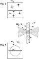
- Figure 2 shows a slit-forming optical element 110 of detection system 50 that creates optical slit 86.
- the slit is transparent for the optical radiation of the system, while an opaque body 112 around the slit prevents transmission of the optical radiation through optical element 110 elsewhere.
- Slit 86 may, for example, be created by an opening (an air gap) in body 112 or as an unmasked area on an otherwise masked surface of body 112.
- the slit is elongated orthogonal to optical path 77 followed by beam 76 at optical element 110, and elongated orthogonal to a direction of elongation of channel 60 (and fluid flow) through irradiation zone 66 (after correcting for a change in direction, if any, in the optical path between optical slit 86 and irradiation zone 66 (e.g., a change in direction created by a mirror)).
- Figure 3 shows irradiation zone 66 of channel 60 in more detail.
- Optical elements located in the optical path between slit 86 and channel 60 may collimate beam 76 and then focus the beam 76 on a section of the channel.
- the channel may be elongated in an image plane of slit 86 (see Figure 1 ), such that the slit is projected onto the section of the channel to create a volume within the channel that is irradiated by beam 76.
- This volume which is stippled distinctly in Figure 3 , is equivalent to irradiation zone 66, and may be described as a detection volume because the changing contents of this volume, as carrier fluid and particles flow through channel 60, may be a primary determinant of how much light is sensed by each detector over time.
- the width of slit 86 may, for example, be selected according to the diameter (or length) of particles 52 being detected, such that projected slit width 114 is less than the diameter (or length) of particles 52.
- the projected slit width is about 40-90%, 50-80%, or 60-70% of the particle diameter (or length).
- the length of the particles is defined in channel 60 as each particle passes through the irradiation zone.
- Figure 4 shows mask 90 of detection system 50.
- the mask may block any suitable transverse portion of the beam.
- the mask may be a line mask that provides a narrow, elongated, non-transmissive region, namely, a line 120 to block a portion of beam 76.
- Line 120 may be oriented parallel to optical slit 86, and may or may not be centered on beam 76 and/or optical axis 78.
- the mask may, for example, be formed by a transparent substrate 122 having an opaque coating to create an opaque line 120.
- substrate 122 may be formed of glass, and line 120 may be produced by chromium etching of an elongated surface region of the glass.
- the mask may be considered to be the entire optical element or only an opaque region thereof.
- the line mask may be created by a discrete elongated member, such as a thin wire.
- the mask may have a different shape of masking element, such as a non-elongated shape (e.g., a circle or square) to create a point mask.
- Line 120 may have any suitable size and position.
- the line may be longer than the diameter of beam 76, as shown in Figure 4 .
- the width of line 120 may be substantially less than the beam's diameter, such as less than about 20%, 10%, or 5%, among others, of the diameter.
- the line may block any suitable portion of the beam's cross-sectional area (and/or light), such as less than about 10%, 5%, or 2%, among others.
- Exemplary widths of line 120 include less than about 1 mm, 700 ⁇ m, or 400 ⁇ m, among others.
- Figure 5 shows an embodiment 130 of detection system 50.
- Beam 76 is stippled to illustrate how mask 90 blocks a portion of the beam to form a shadow region 132 (interchangeably termed a dark region) in the beam.
- Portions of the shadow region may be located optically upstream and downstream of the irradiation zone (and channel 60). However, in the depicted embodiment, the downstream portion provides a location for detection of deflected light.
- the shadow region may represent any suitable portion of a beam angle 134 defined by a diverging region of the beam extending away from channel 60 toward deflection detector 72.
- the shadow region may define a shadow region angle 136 of less than about 8, 6, 5, 4, 3, or 2 degrees.
- Deflection detector 72 has a photosensitive area 138 that is aligned with shadow region 132.
- An optical slit 140 defined by optical element 94 is sized and positioned to prevent undeflected light 142 of beam 76 from striking photosensitive area 138. In other words, optical slit 140 may be narrower than the width of shadow region 132 where the beam strikes optical element 94.
- Optical slit 140 may be located in the image plane of mask 90.
- Deflection detector 72 is positioned behind (downstream from) optical element 94 and its slit 140 and detects light from beam 76 that is deflected into the shadow region. A suitable position for slit 140 and/or deflection detector 72 may be determined by the proximity of mask 90 to the back focal plane of objective 92.
- the image plane for the mask is located at infinity behind channel 60. Accordingly, the mask can be positioned with an offset from the back focal plane to move the mask's image plane to a convenient distance from channel 60.
- Photosensitive area 138 of detector 72 may be positioned near the image plane of the mask, such as close to and directly behind slit 140.
- light that has passed through the irradiation zone, and particularly deflected light can be focused with an optical element, as described below in Example 1.
- the slit may be located in the mask's image plane. Moving the slit closer to or farther from the objective, and therefore out of the image plane, rapidly reduces contrast of the mask image and increases noise. The contrast is reduced because the slit has a finite width, and the light coming though it may not be perfectly collimated when incident on the mask.
- An idealized, masked beam pattern i.e., a sharp mask shadow at any downstream position, shown in Figure 1 , only may occur for a mask inserted in a perfectly collimated beam.
- a mask image formed in an image plane of mask may or may not be magnified or minified with respect the physical mask.
- the image of the mask is minified 0.5x relative to the physical mask. For example, if a line of the physical mask has a width of 300 ⁇ m, the width of the line in the mask image may be 150 ⁇ m.
- Detection system 130 illustrates additional exemplary aspects of system 50 of Figure 1 .
- system 130 incorporates an objective 92 formed by two or more lenses, which may be pre-assembled with one another to create a unit.
- the objective is a Meiji objective having 40x magnification, a numerical aperture of 0.6, and a working distance of 2.8 mm.
- a spatial filter 143 providing a 2x magnification is formed by lenses 84 and 88, and slit-forming optical element 110.
- fluidics subsystem 54 is designed to transport droplets 144 (as particles 52) through irradiation zone 66 in a channel-forming member 146 that is planar.
- the droplets are disposed in an immiscible carrier liquid 148 (e.g., oil).
- the separation, if any, between droplets approaching irradiation zone 66 may be increased by introduction of additional carrier fluid 150 from one or more dilution channels at a channel junction 154 that is fluidically upstream of irradiation zone 66.
- Channel member 146 also may have an inlet 156 for ingress of additional carrier fluid and an outlet 158 for egress of droplets 144 after passing through the irradiation zone.
- Figures 6-9 show exemplary deflection of light within detection system 50 as a particle (e.g., a droplet 144) passes through irradiation zone 66.
- a particle e.g., a droplet 14
- the entire droplet is outside of irradiation zone 66. No deflected light reaches deflection detector 72.
- a leading edge of the droplet has entered the irradiation zone, which produces deflected light 160 that enters shadow region 132 sufficiently to pass through optical slit 140 and reach detector 72.
- the droplet is roughly centered in the irradiation zone and produces deflected light 160 that enters shadow region 132 from both branches 162 of beam 76.
- each branch 162 also called a beam portion, may have about the same intensity if the line mask is centered on the beam.
- the trailing edge of the droplet has entered the irradiation zone, producing deflected light 160 that enters shadow region 132 sufficiently to pass through optical slit 140 and reach detector 72.
- This section describes exemplary aspects of the fluidics subsystem and exemplary carrier fluid and particles therein.
- the fluidics subsystem includes at least one channel 60 to contain and direct movement of carrier fluid and particles.
- the channel may have any suitable cross-sectional shape, such as circular, elliptical, or polygonal.
- the channel may have a cross-sectional dimension that is approximately the same as or greater than the diameter of the particles.
- the channel is a microfluidic channel, namely, a channel having a cross-sectional dimension less than about 1 mm.
- Exemplary channels have a length that is at least about 2, 5, 10, or 20 times the minimum cross-sectional dimension of the channel.
- the channel may be a circumferentially-enclosed passage defined in a planar member, or may be an enclosed passage defined inside a tube (e.g., a tube with a cylindrical exterior).
- the channel may be formed at least in part by molding, wet etching, dry etching, laser etching, or machining.
- the fluidics subsystem may include a source of negative pressure (a vacuum) to pull fluid along the channel, positive pressure to push fluid along the channel, or both.
- a source of negative pressure a vacuum
- the pressure may be created by a pump.
- the pump may be a positive-displacement pump, such as a syringe pump, among others.
- Other exemplary pumps include peristaltic pumps, or rotary pumps.
- the pressure may be provided by a container introduced to the system while holding pressurized gas or a vacuum.
- the carrier fluid may be any suitable liquid or gas phase capable of transporting the particles along the channel.
- the carrier fluid and the particles both may be liquid, for example, a dispersed liquid phase encapsulated by a continuous liquid phase, as in an emulsion.
- the carrier phase may include oil, and optionally a surfactant.
- Suitable oils may include a fluorine-containing oil, a silicone oil, or mineral oil, or any combination thereof, among others.
- the carrier phase may be a gas phase or a liquid phase and the particles may be solid-phase objects
- the carrier phase may be a gas phase and the particles may be droplets (e.g., as an aerosol)
- the carrier phase may be a liquid phase (e.g., an aqueous phase) or a gas phase and the particles may be biological cells.
- Particles detected by the detection system of the present disclosure may exist in any suitable phase, such as a liquid phase, a solid phase, or a combination thereof, among others.
- Exemplary particles include droplets, beads or other small solid-phase objects, and biological cells.
- Particles may have any suitable size. Generally, particles are less than about 1 mm in diameter and/or less than about 1 ⁇ l in volume. The particles may be at least about 1 ⁇ m in diameter and/or at least about 1 fl in volume.
- Particles may have any suitable shape. Exemplary shapes include spherical, cylindrical, bullet-shaped, irregular, or random. Droplets and other particles may have a size and/or shape sensitive to one or more parameters of the fluidics subsystem.
- the diameter and/or shape of the droplets may be influenced by the diameter of channel 60.
- the shape of the droplets may be spherical, and the droplets may have a diameter that is less than the diameter of channel 60. In other cases, the droplets may be elongated, with a diameter corresponding to the channel's diameter.
- the shape of the droplets also may be affected by the flow rate of the carrier fluid, which may determine how much the droplets are stretched or otherwise deformed as they pass through the irradiation zone.
- the droplets may have a surface layer that discourages deformation of the droplets, such that the droplets are relatively insensitive to deformation by the fluidics subsystem.
- the particles may be photoluminescent, namely, capable of emitting light when irradiated with excitation light of the appropriate wavelength.
- exemplary types of photoluminescence include fluorescence, and phosphorescence.
- Each particle may contain a photoluminophore, which is any atom, molecule, moiety, complex, or aggregate capable of photoluminescence.
- Suitable photoluminophores include fluorescent dyes, and quantum dots.
- the optical subsystem may incorporate any suitable number of light sources, such as 1, 2, 3, 4, or more.
- the light sources may be operated to produce optical radiation that reaches the irradiation zone at the same time or at different times (e.g., alternately or sequentially).
- Each light source may generate optical radiation of any suitable wavelength.
- each light source or at least two light sources may emit visible light (e.g., at a different wavelength from other light sources of the system), or at least two light sources may emit different types of optical radiation (e.g., one light source may emit ultraviolet radiation and another light source may emit visible light).
- the light source may incorporate at least one light-emitting element to generate light, and, optionally, one or more optical elements to collect and/or focus the generated light to form a beam.
- exemplary light sources and/or light-emitting elements include electroluminescent lamps (e.g., light-emitting diodes and lasers (such as laser diodes)), and high-intensity discharge lamps (e.g., a mercury arc lamp).
- LEDs include any solid-state device that generates light by electroluminescence, including semiconductor LEDs, organic LEDs, and/or polymer LEDs.
- Each detector also called an optical detector or photodetector, may include at least one photosensor configured to detect light of any suitable wavelength.
- the detector may be a point detector (e.g., a photodiode or photomultiplier) or an image detector.
- Exemplary image detectors include multi-pixel photon counters (MPCC) (e.g., silicon photomultipliers (SiPM)), charge-coupled device (CCD) sensors, or active pixel sensors (e.g., complementary metal-oxide-semiconductor (CMOS) sensors, N-type metal-oxide-semiconductor (NMOS) sensors).
- MPCC multi-pixel photon counters
- SiPM silicon photomultipliers
- CCD charge-coupled device
- active pixel sensors e.g., complementary metal-oxide-semiconductor (CMOS) sensors, N-type metal-oxide-semiconductor (NMOS) sensors.
- CMOS complementary metal-oxide-semicon
- the optical system disclosed herein may be utilized to perform a method of detecting a particle.
- the method steps presented in the section may be performed in any suitable order and combination, and may be modified by any other features and aspects disclosed herein.
- a beam of light may be generated.
- the beam may be generated with at least one light source and may, for example, contain visible light, optionally at least predominantly.
- optical radiation of the light beam may be generated with at least one light-emitting diode or at least one laser.
- the beam may be directed to a channel to create an irradiation zone in the channel where the beam intersects the channel.
- the channel may contain a carrier fluid flowing along the channel through the irradiation zone, with one or more particles disposed in the carrier fluid. Flow of the carrier fluid may move each of the particles through the irradiation zone, optionally serially.
- the flow of the carrier fluid may be driven by a pressure differential, which may be created by a pump.
- the beam may be spatially filtered upstream of the channel. Spatial filtering may be performed at least in part in a focal plane of an optical element(s) of the system.
- the size of the beam may be restricted by spatial filtering, optionally with an elongated slit, such as an air slit, through which light of the beam passes.
- the slit may be arranged orthogonal to the channel (as defined by the long axis of the channel at and around the irradiation zone).
- the beam may be collimated upstream of the slit and focused on the slit.
- the beam may be collimated again at a position downstream of the site at which the beam is spatially filtered and upstream of the channel.
- a transverse portion of the beam may be blocked upstream of the irradiation zone to create a shadow region.
- the shadow region may be created downstream of the region at which the beam is blocked.
- a mask may be used to create the shadow region.
- the mask may be disposed in a collimated region of the beam to block the portion of the beam.
- the beam may be focused on the irradiation zone in the channel using an objective composed of one or more optical elements. Focusing the beam may be performed on a partially blocked region of the beam created by blocking the beam.
- Light of the beam may be deflected by interaction with matter in the irradiation zone.
- the light may be deflected by a particle passing through the irradiation zone.
- the light may be deflected into the shadow region, and may be detected downstream of the irradiation zone.
- the particle passing through the irradiation zone may produce a temporary increase (a pulse) in the intensity of light detected in the shadow zone by a detector.
- the beam may be spatially filtered downstream of the channel, and upstream of the detector, with an optical slit operatively disposed in an optical path between the channel and the detector.
- Photoluminescence induced by the beam at the irradiation zone may be detected.
- the detection of photoluminescence may be epi-fluorescence in which excitation light and emitted light share an optical path followed in respective opposite directions to and from the irradiation zone.
- This example describes exemplary configurations for detecting deflected light in detection system 50 with deflection detector 72, with or without one or more optical elements located between irradiation zone 66 and the detector; see Figures 10-15 .
- Each of the configurations of this example may be incorporated into any of the detection systems of the present disclosure.
- Light may be deflected at the irradiation zone by various mechanisms including refraction, reflection, and Mie scattering.
- the relative contribution of each mechanism may be determined by particle size, shape, composition; carrier fluid properties; and the nature of the interface between each particle and the carrier fluid.
- a carrier fluid comprising oil
- small angle deflection by micelles and large molecules (e.g., proteins) inside a droplet and on its surface, and light refraction and multiple reflection at the interface between the droplet and the oil all may deflect optical radiation into the shadow region.
- the latter effects may deflect incident optical radiation by greater angles, to produce "large angle" deflection.
- the detection system may be configured to detect deflected light of interest from only a portion of the shadow region, to selectively include and exclude deflected light according to the deflection angle.
- Large angle deflection may create a uniform intensity distribution of light across the slit while small angle deflection may bleed around the slit edges. Accordingly, when small angle deflection is more informative about the particles, a portion of the large angle deflection that is located more central to the shadow region can be selectively excluded. Alternatively, small angle deflection closer to the edges of the shadow region can be selectively excluded when large angle deflection is more informative about the particles. With this approach, the background level of the deflection signal may be reduced to increase the sensitivity of the detection system.
- Figure 10 shows a modified version 130' of detection system 130 of Figure 5 .
- System 130' adds a relay lens 170 between irradiation zone 66 and deflection detector 72.
- the relay lens may be located in a focal plane of mask 90 and re-images mask 90 to a greater distance from the irradiation zone (also see Figure 5 ).
- slit-forming element 94 is located in an image plane of the mask at a position farther from the irradiation zone, which may be more convenient if space within system 50 near the irradiation zone is limited, and may increase contrast between the dark image of the mask and the area illuminated adjacent the image by beam 76.
- the aperture of relay lens 170 may be reduced to exclude the beam and, optionally, deflected light near opposite edges of the shadow region, to selectively exclude light deflected by only a small angle.
- the aperture of relay lens 170 may be increased such that a greater amount of large angle deflection is detected, optionally predominantly.
- the relay lens may have an aperture that renders slit-forming element 94 unnecessary.
- Figure 11 shows a fragmentary view of detection system 50 of Figure 1 , taken around flow channel 60 and deflection detector 72.
- the configuration of Figure 11 is presented here as a reference for comparison to the modified configurations of Figures 12-15 .
- Figure 12 shows a modified version 50a of the detection system of Figure 1 with reduced detection of small angle deflection.
- System 50a has a slit-forming element 94a at the same position along the optical path as element 94 of system 50, namely, in the image plane of mask 90 (see Figure 1 ), but defines a narrower optical slit 140a. Accordingly, the width of the slit may be adjusted to reduce background.
- Figure 13 shows yet another modified version 50b of detection system 50.
- System 50b replaces detector 72 with a detector 72b having a smaller photosensitive area 138b.
- Area 138b may be located in the image plane of mask 90 (see Figure 1 ), in place of optical slit 140 (compare with Figure 11 ).
- the photosensitive area may be sized and positioned such that no portion of beam 76 is incident on area 138b (or detected). Instead, only light deflected in irradiation zone 66 can reach area 138b and be detected.
- the size and aspect ratio of area 138b may be selected to at least generally match that of the shadow region in the image plane of the mask.
- area 138b may be elongated parallel to optical slit 86 and/or parallel to a line of mask 90.
- Area 138b may have an aspect ratio of at least about 5:1, or 10:1, among others.
- the width of area 138b may be selected to include or exclude small angle deflection.
- Figure 14 shows still another modified version 50c of detection system 50.
- System 50c is created from system 50 by replacement of downstream optical slit 140 with a slit-forming element 94c having a pair of optical slits 140c that are parallel to one another.
- the pair of optical slits each may be located in the image plane of mask 90 (see Figure 1 ) and may be separated by a masking region 180.
- Masking region 180 reduces detection of large angle deflection.
- another optical slit may be disposed between optical slit 140 of Figure 11 and detector 72.
- Figure 15 shows yet still another modified version 50d of detection system 50.
- a mask 190 is attached to the deflection detector and covers portions of photosensitive area 138.
- Mask 190 may be located out of the mask's image plane. Accordingly, there may be no good correlation between a point on area 138 and the deflection angle of light that can reach that point. However, extra masking or baffling of detector 72 may be effective to control some undesired light that could be present due to light deflection that occurs outside of the detection volume, for example, from an outer surface region of a channel-forming member or various imperfections.
- This example describes intensity distributions calculated with optical modeling software for an exemplary detection system 200; see Figures 16-18 .
- Figure 16 shows detection system 200 having a deflection detector 72 sized and positioned to be illuminated by the full cross-section of beam 76.
- Detector 72 may be an imaging detector configured to detect beam 76 and shadow region 132. Light deflected into the shadow region may be detected as an increased intensity for image pixels representing the shadow region.
- Figure 17 shows a calculated intensity distribution of light in irradiation zone 66 of detection system 200, in a plane orthogonal to the optical path of the beam and bisecting the irradiation zone.
- the intensity distribution was calculated with Zemax ® software for a 100 x 100 ⁇ m region of the plane. Irradiance levels within the image are defined by the scale to the right of the image. Opposite wall regions 210 of channel 60, which delineate part of the irradiation zone, are indicated with dashed lines.
- Figure 18 shows a calculated intensity distribution of light detected by detector 72 of detection system 200.
- the intensity distribution was calculated with Zemax ® software for a 2 x 2 mm square region of the detector. Irradiance values within the image are defined by the scale to the right of the image. Beam 76, shadow region 132, and separate beam portions (branches 162) of the beam are indicated.
- Detection system 130 has a light source 70 (e.g., an LED) and a pair of photoluminescence detectors 74a, 74b each optically coupled to spatial filter 143 and objective 92, in part, by a light guide 220a or 220b.
- Each of the light guides includes an optical fiber 222 that allows the optical paths for excitation and emission to bend, as needed.
- Excitation light produced by light source 70 passes, in order, through light guide 220a, a collimating lens 224, and a spectral filter 226a.
- the excitation light then is reflected toward spatial filter 143 by a beam splitter 82 (here, a long-pass mirror), and propagated through objective 92 and irradiation zone 66, for excitation of a photoluminophore(s) therein and deflection.
- a beam splitter 82 here, a long-pass mirror
- Light emitted from irradiation zone 66 travels in reverse through objective 92, spatial filter 143, beam splitter 82, a spectral filter 226b, a focusing lens 228, light guide 220b, and a collimating lens 230.
- a portion of the collimated, emitted light then passes through a beam splitter 82a to a focusing light guide 232a and detector 74a.
- Another portion of the collimated, emitted light is reflected by beam splitter 82a to focusing light guide 232b and detector 74b.
- Detection system 130 may incorporate one or more additional light sources and/or one or more additional photoluminescence detectors. Accordingly, the detection system may be configured to detect photoluminescence in only one channel with one detector, at least two channels with two detectors (as shown in Figure 19 ), or three or more channels with three or more detectors, among others.
- This example describes exemplary deflection and photoluminescence data collected from droplets with a working model of detection system 130; see Figure 20 .
- Droplets containing a pair of fluorescent dyes were generated.
- the dyes emit light that is detectable with detectors 74a and 74b, respectively (see Figure 19 ).
- the signals registered by detectors 74a and 74b are designated as channel 1 (CH1) and channel 2 (CH2) fluorescence, respectively, in Figure 20 .
- a deflection signal was detected by detector 72 synchronously with detection of the signals of the two fluorescence channels by detectors 74a and 74b.
- the intensity of each signal was plotted as a function of time as four droplets were passed through the irradiation zone. Portions of the signals representing the four well-separated droplets are indicated by the letters A, B, C, and D, in Figure 20 .
- Figure 20 shows the deflection signal rising from baseline as the leading edge of each droplet enters the irradiation zone, indicated by a dashed line at 240, and returning to baseline upon exit of the trailing edge of the droplet from the irradiation zone, indicated by a dashed line at 242, to define a transit interval or span 244 for the droplet.
- Variations in the deflection signal caused by the droplet during the transit interval create a droplet waveform 246.
- the waveform includes at least one peak (i.e., a local maximum) and may, as shown, include a leading peak 248 (a first local maximum (a first height)) and a trailing peak 250 (a second local maximum (a second height)) to form a double peak (two local maxima).
- the waveform may have a signature characteristic of a droplet or other particle.
- Peaks 248, 250 may be created by corresponding leading and trailing regions of the droplet (and corresponding waveform), particularly a pair of humps 252, 254 formed by the leading and trailing regions of the droplet.
- the humps may create a valley 256 (a local minimum) located temporally intermediate the pair of peaks.
- Any suitable characterizing value(s) calculated from the waveform and/or features thereof may contribute to analysis of droplet size, droplet shape, and/or flow velocity of fluid through the irradiation zone.
- the characterizing values of a waveform may include the width/time interval of the waveform measured at baseline, and/or at one-half the maximum amplitude or waveform height, among others.
- the characterizing values also or alternatively may include a separation value 258 corresponding to a temporal separation between the peaks within the waveform.
- the characterizing values also or alternatively may include a relative size (height and/or width) of the leading and trailing regions of the waveform relative to one another, a ratio of a peak or waveform height and the local minimum between peaks, and/or a period between waveforms.
- This example describes further exemplary aspects of particle detection systems.
- the detection system may be based on focused light of any detectable wavelength being deflected by a particle, such as a droplet, while the particle is in the detection volume.
- a particle such as a droplet
- at least three mechanisms e.g., Mie scattering, refraction, and reflection
- the detection of deflected light may be accompanied with measuring the fluorescence intensity originating from dye molecules inside particles, such as droplets.
- the same light source may be used to generate deflection and fluorescence signals, and thus optical radiation from the light source may be referred to as excitation light. Processing of synchronously-acquired deflection and fluorescence signals increases the accuracy of the amplitude and span of the fluorescence signal of each particle, in particular for particles having only weak (or no) fluorescence.
- the detection system is based on blocking a fraction of the collimated excitation light before it is focused by an objective into a detection volume.
- An air slit and the magnification produced by a collimating lens and a focusing objective may define a detection volume inside a flow channel.
- a line mask may be located at the back focal plane of the focusing objective or, when the back focal plane is inaccessible, as close to it as possible. Most large-magnification objectives have the back focal plane inside their bodies. Testing was performed with a line mask constituted by a thin, straight black wire. The wire was mounted to the back aperture of the focusing objective. The direction of the wire was aligned with the direction of the air slit.
- the focusing objective creates an image of the line mask at a certain distance behind the detection volume.
- Another air slit may block light outside of the shadow region, and a light detector may detect light intensity right behind the air slit.
- the air slit in front of the deflection detector may be selected to have its width slightly narrower than the line mask image and its direction may be aligned with the direction of the line mask image.
- the deflection detector stays in darkness until a particle enters the detection volume. The presence of the particle changes the paths of light rays across the detection volume and some light reaches the deflection detector, creating a deflection signal.
- the disclosed detection scheme is different from the layout of a forward scattering channel used in many flow cytometers.
- a narrow laser beam focused with a relatively long focal length lens (e.g., 50-100 mm) into a flow channel, is entirely blocked with an opaque optical stop at the other side of the channel, while small angle scattered light is detected around the stop.
- the detection system disclosed herein has various advantages over flow cytometers having a forward scattering channel.
- First there may be no need to use a high quality laser beam, i.e., a beam that is both narrow and well-collimated.
- the optical detection system disclosed herein was tested with low-cost, high-power LEDs coupled to multimode optical fibers, as well as with diode lasers coupled to the same multimode optical fibers, and demonstrated comparable performance with the different light sources.
- any light source that can be coupled into a large-core optical fiber and then collimated may be suitable for the detection of deflected light, as described herein.
- Second there may be no need to use a second objective to collect fluorescence.
- a separate high numerical aperture objective mounted at 90 degrees with respect to the excitation laser optical path collects light emitted by fluorescence.
- the focusing objective of the present disclosure may be configured to have a short working distance and high numerical aperture, which allows construction of an epi-fluorescence confocal layout, as shown in Figure 1 , where the same objective focuses the irradiation/excitation beam on the detection volume and collects light emitted by fluorescence.
- the registered fluorescence amplitudes shown in Figure 20 were acquired in an epi-fluorescence confocal mode.
- a black line mask at the main objective back aperture creates a shadow across the illuminated area at the opposite side of a flow chip (a planar member defining a flow channel).
- the shadow half angle is two degrees.
- a photodiode with an air slit in front of it normally stays in the shadow. Once a droplet enters the detection volume, the droplet deflects some of the excitation light, which passes through the slit and generates photocurrent. With a droplet-diameter-to-wavelength ratio around 100, Mie theory predicts negligible scattering at angles above two degrees, so the detection mechanism may be based on droplet "lensing" due to a lower refractive index of water (1.33) than silicone oil (1.39).
- the mask preferentially may be a long line due to a round flow channel serving as a negative power cylindrical lens, such that a round spot mask (a point mask) creates little shadow.
- the mask does not interfere with the image formation of a telescope's slit, i.e., the detection area is still a sharp, uniformly-illuminated line. Total light losses due to both excitation light and fluorescence being masked by the mask may stay below 5, 4, 3, or 2 percent.
Landscapes
- Chemical & Material Sciences (AREA)
- Health & Medical Sciences (AREA)
- Immunology (AREA)
- Physics & Mathematics (AREA)
- Life Sciences & Earth Sciences (AREA)
- Analytical Chemistry (AREA)
- Biochemistry (AREA)
- General Health & Medical Sciences (AREA)
- General Physics & Mathematics (AREA)
- Pathology (AREA)
- Dispersion Chemistry (AREA)
- Chemical Kinetics & Catalysis (AREA)
- Optics & Photonics (AREA)
- Nuclear Medicine, Radiotherapy & Molecular Imaging (AREA)
- Investigating, Analyzing Materials By Fluorescence Or Luminescence (AREA)
Claims (12)
- Nachweissystem für Teilchen, umfassend:einen Kanal (60);eine Lichtquelle (70), die so konfiguriert ist, dass sie Licht erzeugen kann;ein oder mehrere optische Elemente (80, 84, 88, 92), die so konfiguriert sind, dass sie einen Strahl des Lichts auf eine Bestrahlungszone (66) innerhalb des Kanals fokussieren;eine Maske (90), die funktionell in einem Lichtweg zwischen der Lichtquelle und dem Kanal angeordnet ist, wobei die Maske so konfiguriert ist, dass sie einen Teil des Strahls blockiert, wodurch ein Schattenbereich entsteht;einen optischen Spalt (86), der sich in einem Lichtweg zwischen der Lichtquelle und dem Kanal befindet;einen ersten Detektor (72), der so konfiguriert ist, dass er Licht, das durch Wechselwirkung mit einem Teilchen, das durch die Bestrahlungszone getreten ist, aus dem Strahl in den Schattenbereich abgelenkt wurde, nachweist; undeinen zweiten Detektor (74), der so konfiguriert ist, dass er durch den Strahl in der Bestrahlungszone induzierte Photolumineszenz nachweist;wobei das eine oder die mehreren optischen Elemente ein Objektiv (96) ergeben, das emittiertes Licht aus der Bestrahlungszone sammelt, damit es sich zum zweiten Detektor ausbreitet; undwobei dieselbe Lichtquelle sowohl Licht, das von dem Teilchen in der Bestrahlungszone abgelenkt und von dem ersten Detektor nachgewiesen wird, als auch Anregungslicht, das in der Bestrahlungszone Photolumineszenz für den Nachweis durch den zweiten Detektor induziert, erzeugt.
- Nachweissystem gemäß Anspruch 1, wobei die Maske eine Linienmaske (120) ist.
- Nachweissystem gemäß Anspruch 1 oder 2, wobei sich der optische Spalt auf einer Position befindet, die der Maske optisch vorgeschaltet ist, wobei vorzugsweise(i) die Maske eine Linienmaske ist, die einen maskierenden Bereich umfasst, der länglich parallel zu dem optischen Spalt verläuft, wobei am meisten bevorzugt der maskierende Bereich senkrecht zu einer Fließrichtung in dem Kanal durch die Bestrahlungszone länglich verläuft; und/oder(ii) der optische Spalt ein erster optischer Spalt ist, der weiterhin einen zweiten optischen Spalt (94) umfasst, der funktionell in einem Lichtweg zwischen der Bestrahlungszone und dem ersten Detektor angeordnet ist.
- Nachweissystem gemäß einem der Ansprüche 1 bis 3, wobei das Teilchen aus der Gruppe ausgewählt ist, die aus einem Tröpfchen, einem Festphasenteilchen und einer biologischen Zelle besteht, wobei vorzugsweise das Teilchen ein Tröpfchen ist, das sich in einer unmischbaren Trägerflüssigkeit befindet.
- Nachweissystem gemäß einem der Ansprüche 1 bis 4, wobei(i) der erste Detektor so konfiguriert ist, dass er Licht in der Nähe einer Bildebene der Maske nachweist; und/oder(ii) das durch das Teilchen aus dem Strahl in den Schattenbereich abgelenkte Licht nicht mit einem optischen Element zwischen dem Kanal und dem ersten Detektor in Wechselwirkung tritt.
- Nachweissystem gemäß einem der Ansprüche 1 bis 5, weiterhin umfassend wenigstens eine Quelle von Überdruck/Unterdruck, die funktionell mit dem Kanal verbunden und so konfiguriert ist, dass ein Druckunterschied entsteht, der die Fluidströmung durch den Kanal antreibt.
- Nachweissystem gemäß einem der Ansprüche 1 bis 6, weiterhin umfassend eine Quelle von Trägerflüssigkeit, die sich in Fluidkommunikation mit dem Kanal befindet, wobei vorzugsweise(i) die Quelle von Trägerflüssigkeit interessierende Teilchen enthält, weiterhin umfassend eine Quelle von Verdünnungsflüssigkeit in Fluidkommunikation mit dem Kanal und so konfiguriert, dass sie den Abstand zwischen Teilchen in dem Kanal auf einer Position, die der Bestrahlungszone fluidisch vorgeschaltet ist, durch Verdünnung der Trägerflüssigkeit, die interessierende Teilchen enthält, mit der Verdünnungsflüssigkeit erhöht; und/oder(ii) das Nachweissystem weiterhin wenigstens eine Quelle von Überdruck/ Unterdruck umfasst, die funktionell mit der Quelle von Trägerflüssigkeit verbunden und so konfiguriert ist, dass ein Druckunterschied entsteht, der die Strömung der Trägerflüssigkeit durch den Kanal antreibt.
- Verfahren zum Nachweisen eines Teilchens, wobei das Verfahren umfasst:Erzeugen eines Lichtstrahls;Blockieren eines Teils des Strahls an einem Ort, der einem Kanal optisch vorgeschaltet ist, so dass ein Schattenbereich entsteht;Fokussieren des Strahls auf eine Bestrahlungszone innerhalb des Kanals;Leiten eines Teilchens durch die Bestrahlungszone, wobei der Schritt des Leitens Licht durch Wechselwirkung mit dem Teilchen in den Schattenbereich lenkt;räumliches Filtern des Lichts des Strahls mit einem optischen Spalt, der sich in einem Lichtweg zwischen dem Kanal und einem ersten Detektor befindet;Nachweisen von Licht in dem Schattenbereich mit Hilfe des ersten Detektors, wobei das in dem Schattenbereich nachgewiesene Licht zwischen dem Kanal und dem ersten Detektor nicht fokussiert wird; undNachweisen von Photolumineszenz, die durch den Strahl in der Bestrahlungszone induziert wird, mit einem zweiten Detektor.
- Verfahren gemäß Anspruch 8, wobei der Schritt des Fokussierens auf einem partiell blockierten Bereich des Strahls, der aus dem Schritt des Blockierens resultiert, durchgeführt wird.
- Verfahren gemäß Anspruch 8 oder 9, wobei der Schritt des Blockierens mit einer Maske durchgeführt wird, weiterhin umfassend einen Schritt des Leitens von Licht des Strahls durch einen optischen Spalt, der sich funktionell auf einer Position befindet, die der Maske optisch vorgeschaltet ist.
- Verfahren gemäß einem der Ansprüche 8 bis 10, wobei der Schritt des Blockierens einen Schritt des Blockierens eines Teils des Strahls mit einer Linienmaske umfasst, wobei vorzugsweise die Linienmaske einen maskierenden Bereich umfasst, der länglich senkrecht zum Kanal verläuft, und wobei am meisten bevorzugt der maskierende Bereich länglich parallel zu einem optischen Spalt verläuft, der der Linienmaske funktionell vorgeschaltet ist.
- Verfahren gemäß einem der Ansprüche 8 bis 11, wobei der Schritt des Leitens eines Teilchens einen Schritt des Leitens eines Tröpfchens durch die Bestrahlungszone umfasst.
Applications Claiming Priority (2)
| Application Number | Priority Date | Filing Date | Title |
|---|---|---|---|
| US201562273362P | 2015-12-30 | 2015-12-30 | |
| PCT/US2016/069332 WO2017117461A1 (en) | 2015-12-30 | 2016-12-29 | Optical detection system for particles |
Publications (3)
| Publication Number | Publication Date |
|---|---|
| EP3397946A1 EP3397946A1 (de) | 2018-11-07 |
| EP3397946A4 EP3397946A4 (de) | 2019-07-24 |
| EP3397946B1 true EP3397946B1 (de) | 2021-12-01 |
Family
ID=59225750
Family Applications (1)
| Application Number | Title | Priority Date | Filing Date |
|---|---|---|---|
| EP16882705.3A Active EP3397946B1 (de) | 2015-12-30 | 2016-12-29 | Optisches detektionssystem für partikel |
Country Status (4)
| Country | Link |
|---|---|
| US (1) | US9846111B2 (de) |
| EP (1) | EP3397946B1 (de) |
| CN (1) | CN108700500B (de) |
| WO (1) | WO2017117461A1 (de) |
Families Citing this family (15)
| Publication number | Priority date | Publication date | Assignee | Title |
|---|---|---|---|---|
| KR102104987B1 (ko) | 2011-12-01 | 2020-04-28 | 파티클 머슈어링 시스템즈, 인크. | 입자 크기 및 농도 측정을 위한 검출 스킴 |
| ES3026990T3 (en) * | 2017-09-21 | 2025-06-12 | Bit Group France | Optical flow cytometer for epi fluorescence measurement |
| US10578542B2 (en) * | 2017-10-16 | 2020-03-03 | Becton, Dickinson And Company | Multi-photon counting for high sensitivity flow cytometer systems and methods for using the same |
| KR102601473B1 (ko) | 2017-10-26 | 2023-11-10 | 파티클 머슈어링 시스템즈, 인크. | 입자 측정을 위한 시스템 및 방법 |
| EP3633414B1 (de) * | 2018-10-02 | 2022-03-02 | Vaisala, OYJ | Vorwärtsstreuungssensor |
| US11237095B2 (en) | 2019-04-25 | 2022-02-01 | Particle Measuring Systems, Inc. | Particle detection systems and methods for on-axis particle detection and/or differential detection |
| WO2021072306A1 (en) | 2019-10-10 | 2021-04-15 | 1859, Inc. | Methods and systems for microfluidic screening |
| EP4062146A4 (de) | 2019-11-22 | 2024-02-28 | Particle Measuring Systems, Inc. | Fortgeschrittene systeme und verfahren zur interferometrischen teilchendetektion und detektion von teilchen mit kleinen abmessungen |
| CN121476024A (zh) * | 2020-04-01 | 2026-02-06 | 兴科尚株式会社 | 流式细胞仪 |
| WO2021245859A1 (ja) * | 2020-06-03 | 2021-12-09 | 株式会社日立ハイテク | 核酸分析装置 |
| US12409650B2 (en) * | 2020-07-22 | 2025-09-09 | National Technology & Engineering Solutions Of Sandia, Llc | Optical measurement system for real-time process monitoring of aerosol jet printing |
| CN112557311A (zh) * | 2020-09-30 | 2021-03-26 | 安徽北研科仪仪器有限公司 | 一种液体微粒检测器及检测方法 |
| DE102020132574A1 (de) * | 2020-12-08 | 2022-06-09 | ebm-papst neo GmbH & Co. KG | Vorrichtung und Verfahren zur Erfassung einer Konzentration von vorbestimmten Partikeln anhand ihrer morphologischen Eigenschaften in Luft |
| JP2026507735A (ja) * | 2022-12-20 | 2026-03-05 | ビット グループ フランス | 単一の非コヒーレント光源から発せられるビームを分割することによって蛍光及び散乱を測定する光学フローサイトメータ |
| CN119374680B (zh) * | 2024-11-05 | 2025-08-05 | 哈尔滨工业大学 | 基于激光调制的粉末燃料质量流率在线测量装置及其方法 |
Family Cites Families (17)
| Publication number | Priority date | Publication date | Assignee | Title |
|---|---|---|---|---|
| JPS61280548A (ja) * | 1985-06-05 | 1986-12-11 | Canon Inc | 粒子解析装置 |
| JP3213333B2 (ja) * | 1991-05-14 | 2001-10-02 | シスメックス株式会社 | 尿中の細胞分析装置および方法。 |
| US5872627A (en) * | 1996-07-30 | 1999-02-16 | Bayer Corporation | Method and apparatus for detecting scattered light in an analytical instrument |
| EP0979409B1 (de) * | 1997-02-20 | 2006-12-27 | The Regents of the University of California | Plasmon-schwingteilchen, methode und vorrichtung |
| ATE514072T1 (de) * | 1997-05-05 | 2011-07-15 | Chemometec As | Verfahren zur bestimmung von teilchen in einer flüssigen probe |
| US6023324A (en) * | 1997-11-05 | 2000-02-08 | Comco, Inc. | Particle flow monitor and metering system |
| US20070242269A1 (en) * | 2004-03-06 | 2007-10-18 | Michael Trainer | Methods and apparatus for determining characteristics of particles |
| US8124032B2 (en) | 2004-07-16 | 2012-02-28 | Simon Fraser University | Microfluidic device and method of using same |
| MX2007009124A (es) * | 2005-01-31 | 2007-10-08 | Univ Illinois | Metodos y dispositivos para caracterizar particulas en medios transparentes y turbios. |
| US20120252015A1 (en) | 2011-02-18 | 2012-10-04 | Bio-Rad Laboratories | Methods and compositions for detecting genetic material |
| US9156010B2 (en) | 2008-09-23 | 2015-10-13 | Bio-Rad Laboratories, Inc. | Droplet-based assay system |
| JP2011163787A (ja) * | 2010-02-05 | 2011-08-25 | Sony Corp | 微小粒子分析装置及び微小粒子分析方法 |
| JP2013524169A (ja) | 2010-03-25 | 2013-06-17 | クァンタライフ・インコーポレーテッド | 液滴によるアッセイ用の検出システム |
| JP2013137267A (ja) | 2011-12-28 | 2013-07-11 | Sony Corp | マイクロチップ及びマイクロチップ型微小粒子測定装置 |
| DE102012210289A1 (de) | 2012-06-19 | 2013-12-19 | Siemens Aktiengesellschaft | Lichtbasierte Partikeldetektion und Größenbestimmung |
| US11110458B2 (en) * | 2013-02-01 | 2021-09-07 | Bio-Rad Laboratories, Inc. | System for detection of spaced droplets |
| WO2014186228A1 (en) | 2013-05-13 | 2014-11-20 | Chiranjit Deka | Apparatus and methods for cellular analysis |
-
2016
- 2016-12-29 EP EP16882705.3A patent/EP3397946B1/de active Active
- 2016-12-29 WO PCT/US2016/069332 patent/WO2017117461A1/en not_active Ceased
- 2016-12-29 CN CN201680082862.0A patent/CN108700500B/zh active Active
- 2016-12-29 US US15/394,605 patent/US9846111B2/en active Active
Non-Patent Citations (1)
| Title |
|---|
| None * |
Also Published As
| Publication number | Publication date |
|---|---|
| WO2017117461A1 (en) | 2017-07-06 |
| CN108700500B (zh) | 2021-10-29 |
| US9846111B2 (en) | 2017-12-19 |
| CN108700500A (zh) | 2018-10-23 |
| EP3397946A4 (de) | 2019-07-24 |
| EP3397946A1 (de) | 2018-11-07 |
| US20170191924A1 (en) | 2017-07-06 |
Similar Documents
| Publication | Publication Date | Title |
|---|---|---|
| EP3397946B1 (de) | Optisches detektionssystem für partikel | |
| US12352682B2 (en) | Apparatuses, systems and methods for imaging flow cytometry | |
| US10060847B2 (en) | Detection and signal processing system for particle assays | |
| US12313519B2 (en) | Method and apparatus for flow-based, single-particle and/or single-molecule analysis | |
| EP2913656B1 (de) | Bestimmung von Farbeigenschaften von Objekten mit räumlich moduliertem Licht | |
| US11119029B2 (en) | Particle detection using thin lenses | |
| KR102447224B1 (ko) | 미세 입자의 정성 및 정량 분석 장치 | |
| KR20140016923A (ko) | 미생물 검출 장치 및 방법 | |
| US11327002B2 (en) | In-liquid microparticle analysis system and in-liquid microparticle analysis method | |
| KR20230053730A (ko) | 유체 기둥 내 물체로부터의 집광 | |
| WO2016158443A1 (ja) | 微粒子計測装置 |
Legal Events
| Date | Code | Title | Description |
|---|---|---|---|
| STAA | Information on the status of an ep patent application or granted ep patent |
Free format text: STATUS: THE INTERNATIONAL PUBLICATION HAS BEEN MADE |
|
| PUAI | Public reference made under article 153(3) epc to a published international application that has entered the european phase |
Free format text: ORIGINAL CODE: 0009012 |
|
| STAA | Information on the status of an ep patent application or granted ep patent |
Free format text: STATUS: REQUEST FOR EXAMINATION WAS MADE |
|
| 17P | Request for examination filed |
Effective date: 20180713 |
|
| AK | Designated contracting states |
Kind code of ref document: A1 Designated state(s): AL AT BE BG CH CY CZ DE DK EE ES FI FR GB GR HR HU IE IS IT LI LT LU LV MC MK MT NL NO PL PT RO RS SE SI SK SM TR |
|
| AX | Request for extension of the european patent |
Extension state: BA ME |
|
| DAV | Request for validation of the european patent (deleted) | ||
| DAX | Request for extension of the european patent (deleted) | ||
| A4 | Supplementary search report drawn up and despatched |
Effective date: 20190626 |
|
| RIC1 | Information provided on ipc code assigned before grant |
Ipc: G01N 15/14 20060101AFI20190620BHEP Ipc: G01N 21/53 20060101ALI20190620BHEP |
|
| STAA | Information on the status of an ep patent application or granted ep patent |
Free format text: STATUS: EXAMINATION IS IN PROGRESS |
|
| 17Q | First examination report despatched |
Effective date: 20200630 |
|
| RAP3 | Party data changed (applicant data changed or rights of an application transferred) |
Owner name: BIO-RAD LABORATORIES, INC. |
|
| GRAP | Despatch of communication of intention to grant a patent |
Free format text: ORIGINAL CODE: EPIDOSNIGR1 |
|
| STAA | Information on the status of an ep patent application or granted ep patent |
Free format text: STATUS: GRANT OF PATENT IS INTENDED |
|
| INTG | Intention to grant announced |
Effective date: 20210615 |
|
| GRAS | Grant fee paid |
Free format text: ORIGINAL CODE: EPIDOSNIGR3 |
|
| GRAA | (expected) grant |
Free format text: ORIGINAL CODE: 0009210 |
|
| STAA | Information on the status of an ep patent application or granted ep patent |
Free format text: STATUS: THE PATENT HAS BEEN GRANTED |
|
| AK | Designated contracting states |
Kind code of ref document: B1 Designated state(s): AL AT BE BG CH CY CZ DE DK EE ES FI FR GB GR HR HU IE IS IT LI LT LU LV MC MK MT NL NO PL PT RO RS SE SI SK SM TR |
|
| REG | Reference to a national code |
Ref country code: GB Ref legal event code: FG4D |
|
| REG | Reference to a national code |
Ref country code: AT Ref legal event code: REF Ref document number: 1452219 Country of ref document: AT Kind code of ref document: T Effective date: 20211215 Ref country code: CH Ref legal event code: EP |
|
| REG | Reference to a national code |
Ref country code: IE Ref legal event code: FG4D |
|
| REG | Reference to a national code |
Ref country code: DE Ref legal event code: R096 Ref document number: 602016066994 Country of ref document: DE |
|
| REG | Reference to a national code |
Ref country code: LT Ref legal event code: MG9D |
|
| REG | Reference to a national code |
Ref country code: NL Ref legal event code: MP Effective date: 20211201 |
|
| REG | Reference to a national code |
Ref country code: AT Ref legal event code: MK05 Ref document number: 1452219 Country of ref document: AT Kind code of ref document: T Effective date: 20211201 |
|
| PG25 | Lapsed in a contracting state [announced via postgrant information from national office to epo] |
Ref country code: RS Free format text: LAPSE BECAUSE OF FAILURE TO SUBMIT A TRANSLATION OF THE DESCRIPTION OR TO PAY THE FEE WITHIN THE PRESCRIBED TIME-LIMIT Effective date: 20211201 Ref country code: LT Free format text: LAPSE BECAUSE OF FAILURE TO SUBMIT A TRANSLATION OF THE DESCRIPTION OR TO PAY THE FEE WITHIN THE PRESCRIBED TIME-LIMIT Effective date: 20211201 Ref country code: FI Free format text: LAPSE BECAUSE OF FAILURE TO SUBMIT A TRANSLATION OF THE DESCRIPTION OR TO PAY THE FEE WITHIN THE PRESCRIBED TIME-LIMIT Effective date: 20211201 Ref country code: BG Free format text: LAPSE BECAUSE OF FAILURE TO SUBMIT A TRANSLATION OF THE DESCRIPTION OR TO PAY THE FEE WITHIN THE PRESCRIBED TIME-LIMIT Effective date: 20220301 Ref country code: AT Free format text: LAPSE BECAUSE OF FAILURE TO SUBMIT A TRANSLATION OF THE DESCRIPTION OR TO PAY THE FEE WITHIN THE PRESCRIBED TIME-LIMIT Effective date: 20211201 |
|
| PG25 | Lapsed in a contracting state [announced via postgrant information from national office to epo] |
Ref country code: SE Free format text: LAPSE BECAUSE OF FAILURE TO SUBMIT A TRANSLATION OF THE DESCRIPTION OR TO PAY THE FEE WITHIN THE PRESCRIBED TIME-LIMIT Effective date: 20211201 Ref country code: PL Free format text: LAPSE BECAUSE OF FAILURE TO SUBMIT A TRANSLATION OF THE DESCRIPTION OR TO PAY THE FEE WITHIN THE PRESCRIBED TIME-LIMIT Effective date: 20211201 Ref country code: NO Free format text: LAPSE BECAUSE OF FAILURE TO SUBMIT A TRANSLATION OF THE DESCRIPTION OR TO PAY THE FEE WITHIN THE PRESCRIBED TIME-LIMIT Effective date: 20220301 Ref country code: LV Free format text: LAPSE BECAUSE OF FAILURE TO SUBMIT A TRANSLATION OF THE DESCRIPTION OR TO PAY THE FEE WITHIN THE PRESCRIBED TIME-LIMIT Effective date: 20211201 Ref country code: HR Free format text: LAPSE BECAUSE OF FAILURE TO SUBMIT A TRANSLATION OF THE DESCRIPTION OR TO PAY THE FEE WITHIN THE PRESCRIBED TIME-LIMIT Effective date: 20211201 Ref country code: GR Free format text: LAPSE BECAUSE OF FAILURE TO SUBMIT A TRANSLATION OF THE DESCRIPTION OR TO PAY THE FEE WITHIN THE PRESCRIBED TIME-LIMIT Effective date: 20220302 Ref country code: ES Free format text: LAPSE BECAUSE OF FAILURE TO SUBMIT A TRANSLATION OF THE DESCRIPTION OR TO PAY THE FEE WITHIN THE PRESCRIBED TIME-LIMIT Effective date: 20211201 |
|
| PG25 | Lapsed in a contracting state [announced via postgrant information from national office to epo] |
Ref country code: NL Free format text: LAPSE BECAUSE OF FAILURE TO SUBMIT A TRANSLATION OF THE DESCRIPTION OR TO PAY THE FEE WITHIN THE PRESCRIBED TIME-LIMIT Effective date: 20211201 |
|
| PG25 | Lapsed in a contracting state [announced via postgrant information from national office to epo] |
Ref country code: SM Free format text: LAPSE BECAUSE OF FAILURE TO SUBMIT A TRANSLATION OF THE DESCRIPTION OR TO PAY THE FEE WITHIN THE PRESCRIBED TIME-LIMIT Effective date: 20211201 Ref country code: SK Free format text: LAPSE BECAUSE OF FAILURE TO SUBMIT A TRANSLATION OF THE DESCRIPTION OR TO PAY THE FEE WITHIN THE PRESCRIBED TIME-LIMIT Effective date: 20211201 Ref country code: RO Free format text: LAPSE BECAUSE OF FAILURE TO SUBMIT A TRANSLATION OF THE DESCRIPTION OR TO PAY THE FEE WITHIN THE PRESCRIBED TIME-LIMIT Effective date: 20211201 Ref country code: PT Free format text: LAPSE BECAUSE OF FAILURE TO SUBMIT A TRANSLATION OF THE DESCRIPTION OR TO PAY THE FEE WITHIN THE PRESCRIBED TIME-LIMIT Effective date: 20220401 Ref country code: EE Free format text: LAPSE BECAUSE OF FAILURE TO SUBMIT A TRANSLATION OF THE DESCRIPTION OR TO PAY THE FEE WITHIN THE PRESCRIBED TIME-LIMIT Effective date: 20211201 Ref country code: CZ Free format text: LAPSE BECAUSE OF FAILURE TO SUBMIT A TRANSLATION OF THE DESCRIPTION OR TO PAY THE FEE WITHIN THE PRESCRIBED TIME-LIMIT Effective date: 20211201 |
|
| REG | Reference to a national code |
Ref country code: CH Ref legal event code: PL |
|
| PG25 | Lapsed in a contracting state [announced via postgrant information from national office to epo] |
Ref country code: MC Free format text: LAPSE BECAUSE OF FAILURE TO SUBMIT A TRANSLATION OF THE DESCRIPTION OR TO PAY THE FEE WITHIN THE PRESCRIBED TIME-LIMIT Effective date: 20211201 |
|
| REG | Reference to a national code |
Ref country code: DE Ref legal event code: R097 Ref document number: 602016066994 Country of ref document: DE |
|
| REG | Reference to a national code |
Ref country code: BE Ref legal event code: MM Effective date: 20211231 |
|
| PG25 | Lapsed in a contracting state [announced via postgrant information from national office to epo] |
Ref country code: IS Free format text: LAPSE BECAUSE OF FAILURE TO SUBMIT A TRANSLATION OF THE DESCRIPTION OR TO PAY THE FEE WITHIN THE PRESCRIBED TIME-LIMIT Effective date: 20220401 |
|
| PLBE | No opposition filed within time limit |
Free format text: ORIGINAL CODE: 0009261 |
|
| STAA | Information on the status of an ep patent application or granted ep patent |
Free format text: STATUS: NO OPPOSITION FILED WITHIN TIME LIMIT |
|
| PG25 | Lapsed in a contracting state [announced via postgrant information from national office to epo] |
Ref country code: IE Free format text: LAPSE BECAUSE OF NON-PAYMENT OF DUE FEES Effective date: 20211229 Ref country code: DK Free format text: LAPSE BECAUSE OF FAILURE TO SUBMIT A TRANSLATION OF THE DESCRIPTION OR TO PAY THE FEE WITHIN THE PRESCRIBED TIME-LIMIT Effective date: 20211201 Ref country code: AL Free format text: LAPSE BECAUSE OF FAILURE TO SUBMIT A TRANSLATION OF THE DESCRIPTION OR TO PAY THE FEE WITHIN THE PRESCRIBED TIME-LIMIT Effective date: 20211201 Ref country code: LU Free format text: LAPSE BECAUSE OF NON-PAYMENT OF DUE FEES Effective date: 20211229 |
|
| 26N | No opposition filed |
Effective date: 20220902 |
|
| PG25 | Lapsed in a contracting state [announced via postgrant information from national office to epo] |
Ref country code: SI Free format text: LAPSE BECAUSE OF FAILURE TO SUBMIT A TRANSLATION OF THE DESCRIPTION OR TO PAY THE FEE WITHIN THE PRESCRIBED TIME-LIMIT Effective date: 20211201 Ref country code: BE Free format text: LAPSE BECAUSE OF NON-PAYMENT OF DUE FEES Effective date: 20211231 |
|
| PG25 | Lapsed in a contracting state [announced via postgrant information from national office to epo] |
Ref country code: LI Free format text: LAPSE BECAUSE OF NON-PAYMENT OF DUE FEES Effective date: 20211231 Ref country code: CH Free format text: LAPSE BECAUSE OF NON-PAYMENT OF DUE FEES Effective date: 20211231 |
|
| PG25 | Lapsed in a contracting state [announced via postgrant information from national office to epo] |
Ref country code: IT Free format text: LAPSE BECAUSE OF FAILURE TO SUBMIT A TRANSLATION OF THE DESCRIPTION OR TO PAY THE FEE WITHIN THE PRESCRIBED TIME-LIMIT Effective date: 20211201 |
|
| P01 | Opt-out of the competence of the unified patent court (upc) registered |
Effective date: 20230426 |
|
| PG25 | Lapsed in a contracting state [announced via postgrant information from national office to epo] |
Ref country code: CY Free format text: LAPSE BECAUSE OF FAILURE TO SUBMIT A TRANSLATION OF THE DESCRIPTION OR TO PAY THE FEE WITHIN THE PRESCRIBED TIME-LIMIT Effective date: 20211201 |
|
| PG25 | Lapsed in a contracting state [announced via postgrant information from national office to epo] |
Ref country code: HU Free format text: LAPSE BECAUSE OF FAILURE TO SUBMIT A TRANSLATION OF THE DESCRIPTION OR TO PAY THE FEE WITHIN THE PRESCRIBED TIME-LIMIT; INVALID AB INITIO Effective date: 20161229 |
|
| PG25 | Lapsed in a contracting state [announced via postgrant information from national office to epo] |
Ref country code: MK Free format text: LAPSE BECAUSE OF FAILURE TO SUBMIT A TRANSLATION OF THE DESCRIPTION OR TO PAY THE FEE WITHIN THE PRESCRIBED TIME-LIMIT Effective date: 20211201 |
|
| PG25 | Lapsed in a contracting state [announced via postgrant information from national office to epo] |
Ref country code: MT Free format text: LAPSE BECAUSE OF FAILURE TO SUBMIT A TRANSLATION OF THE DESCRIPTION OR TO PAY THE FEE WITHIN THE PRESCRIBED TIME-LIMIT Effective date: 20211201 |
|
| PG25 | Lapsed in a contracting state [announced via postgrant information from national office to epo] |
Ref country code: TR Free format text: LAPSE BECAUSE OF FAILURE TO SUBMIT A TRANSLATION OF THE DESCRIPTION OR TO PAY THE FEE WITHIN THE PRESCRIBED TIME-LIMIT Effective date: 20211201 |
|
| PGFP | Annual fee paid to national office [announced via postgrant information from national office to epo] |
Ref country code: GB Payment date: 20251223 Year of fee payment: 10 |
|
| PGFP | Annual fee paid to national office [announced via postgrant information from national office to epo] |
Ref country code: FR Payment date: 20251223 Year of fee payment: 10 |
|
| PGFP | Annual fee paid to national office [announced via postgrant information from national office to epo] |
Ref country code: DE Payment date: 20251229 Year of fee payment: 10 |