EP3398552A1 - Commande de visionneuse d'images médicales à partir de la caméra du chirurgien - Google Patents
Commande de visionneuse d'images médicales à partir de la caméra du chirurgien Download PDFInfo
- Publication number
- EP3398552A1 EP3398552A1 EP18170432.1A EP18170432A EP3398552A1 EP 3398552 A1 EP3398552 A1 EP 3398552A1 EP 18170432 A EP18170432 A EP 18170432A EP 3398552 A1 EP3398552 A1 EP 3398552A1
- Authority
- EP
- European Patent Office
- Prior art keywords
- patient
- location
- camera
- slice image
- laparoscopic camera
- Prior art date
- Legal status (The legal status is an assumption and is not a legal conclusion. Google has not performed a legal analysis and makes no representation as to the accuracy of the status listed.)
- Withdrawn
Links
Images


Classifications
-
- A—HUMAN NECESSITIES
- A61—MEDICAL OR VETERINARY SCIENCE; HYGIENE
- A61B—DIAGNOSIS; SURGERY; IDENTIFICATION
- A61B90/00—Instruments, implements or accessories specially adapted for surgery or diagnosis and not covered by any of the groups A61B1/00 - A61B50/00, e.g. for luxation treatment or for protecting wound edges
- A61B90/36—Image-producing devices or illumination devices not otherwise provided for
- A61B90/37—Surgical systems with images on a monitor during operation
-
- A—HUMAN NECESSITIES
- A61—MEDICAL OR VETERINARY SCIENCE; HYGIENE
- A61B—DIAGNOSIS; SURGERY; IDENTIFICATION
- A61B1/00—Instruments for performing medical examinations of the interior of cavities or tubes of the body by visual or photographical inspection, e.g. endoscopes; Illuminating arrangements therefor
- A61B1/00002—Operational features of endoscopes
- A61B1/00004—Operational features of endoscopes characterised by electronic signal processing
- A61B1/00009—Operational features of endoscopes characterised by electronic signal processing of image signals during a use of endoscope
-
- A—HUMAN NECESSITIES
- A61—MEDICAL OR VETERINARY SCIENCE; HYGIENE
- A61B—DIAGNOSIS; SURGERY; IDENTIFICATION
- A61B1/00—Instruments for performing medical examinations of the interior of cavities or tubes of the body by visual or photographical inspection, e.g. endoscopes; Illuminating arrangements therefor
- A61B1/00002—Operational features of endoscopes
- A61B1/00004—Operational features of endoscopes characterised by electronic signal processing
- A61B1/00006—Operational features of endoscopes characterised by electronic signal processing of control signals
-
- A—HUMAN NECESSITIES
- A61—MEDICAL OR VETERINARY SCIENCE; HYGIENE
- A61B—DIAGNOSIS; SURGERY; IDENTIFICATION
- A61B1/00—Instruments for performing medical examinations of the interior of cavities or tubes of the body by visual or photographical inspection, e.g. endoscopes; Illuminating arrangements therefor
- A61B1/00002—Operational features of endoscopes
- A61B1/00004—Operational features of endoscopes characterised by electronic signal processing
- A61B1/00009—Operational features of endoscopes characterised by electronic signal processing of image signals during a use of endoscope
- A61B1/000095—Operational features of endoscopes characterised by electronic signal processing of image signals during a use of endoscope for image enhancement
-
- A—HUMAN NECESSITIES
- A61—MEDICAL OR VETERINARY SCIENCE; HYGIENE
- A61B—DIAGNOSIS; SURGERY; IDENTIFICATION
- A61B1/00—Instruments for performing medical examinations of the interior of cavities or tubes of the body by visual or photographical inspection, e.g. endoscopes; Illuminating arrangements therefor
- A61B1/00002—Operational features of endoscopes
- A61B1/00043—Operational features of endoscopes provided with output arrangements
- A61B1/00045—Display arrangement
- A61B1/0005—Display arrangement combining images e.g. side-by-side, superimposed or tiled
-
- A—HUMAN NECESSITIES
- A61—MEDICAL OR VETERINARY SCIENCE; HYGIENE
- A61B—DIAGNOSIS; SURGERY; IDENTIFICATION
- A61B1/00—Instruments for performing medical examinations of the interior of cavities or tubes of the body by visual or photographical inspection, e.g. endoscopes; Illuminating arrangements therefor
- A61B1/00147—Holding or positioning arrangements
- A61B1/00149—Holding or positioning arrangements using articulated arms
-
- A—HUMAN NECESSITIES
- A61—MEDICAL OR VETERINARY SCIENCE; HYGIENE
- A61B—DIAGNOSIS; SURGERY; IDENTIFICATION
- A61B1/00—Instruments for performing medical examinations of the interior of cavities or tubes of the body by visual or photographical inspection, e.g. endoscopes; Illuminating arrangements therefor
- A61B1/04—Instruments for performing medical examinations of the interior of cavities or tubes of the body by visual or photographical inspection, e.g. endoscopes; Illuminating arrangements therefor combined with photographic or television appliances
- A61B1/05—Instruments for performing medical examinations of the interior of cavities or tubes of the body by visual or photographical inspection, e.g. endoscopes; Illuminating arrangements therefor combined with photographic or television appliances characterised by the image sensor, e.g. camera, being in the distal end portion
-
- A—HUMAN NECESSITIES
- A61—MEDICAL OR VETERINARY SCIENCE; HYGIENE
- A61B—DIAGNOSIS; SURGERY; IDENTIFICATION
- A61B1/00—Instruments for performing medical examinations of the interior of cavities or tubes of the body by visual or photographical inspection, e.g. endoscopes; Illuminating arrangements therefor
- A61B1/267—Instruments for performing medical examinations of the interior of cavities or tubes of the body by visual or photographical inspection, e.g. endoscopes; Illuminating arrangements therefor for the respiratory tract, e.g. laryngoscopes, bronchoscopes
- A61B1/2676—Bronchoscopes
-
- A—HUMAN NECESSITIES
- A61—MEDICAL OR VETERINARY SCIENCE; HYGIENE
- A61B—DIAGNOSIS; SURGERY; IDENTIFICATION
- A61B1/00—Instruments for performing medical examinations of the interior of cavities or tubes of the body by visual or photographical inspection, e.g. endoscopes; Illuminating arrangements therefor
- A61B1/307—Instruments for performing medical examinations of the interior of cavities or tubes of the body by visual or photographical inspection, e.g. endoscopes; Illuminating arrangements therefor for the urinary organs, e.g. urethroscopes, cystoscopes
-
- A—HUMAN NECESSITIES
- A61—MEDICAL OR VETERINARY SCIENCE; HYGIENE
- A61B—DIAGNOSIS; SURGERY; IDENTIFICATION
- A61B1/00—Instruments for performing medical examinations of the interior of cavities or tubes of the body by visual or photographical inspection, e.g. endoscopes; Illuminating arrangements therefor
- A61B1/313—Instruments for performing medical examinations of the interior of cavities or tubes of the body by visual or photographical inspection, e.g. endoscopes; Illuminating arrangements therefor for introducing through surgical openings, e.g. laparoscopes
- A61B1/3132—Instruments for performing medical examinations of the interior of cavities or tubes of the body by visual or photographical inspection, e.g. endoscopes; Illuminating arrangements therefor for introducing through surgical openings, e.g. laparoscopes for laparoscopy
-
- A—HUMAN NECESSITIES
- A61—MEDICAL OR VETERINARY SCIENCE; HYGIENE
- A61B—DIAGNOSIS; SURGERY; IDENTIFICATION
- A61B34/00—Computer-aided surgery; Manipulators or robots specially adapted for use in surgery
- A61B34/20—Surgical navigation systems; Devices for tracking or guiding surgical instruments, e.g. for frameless stereotaxis
-
- A—HUMAN NECESSITIES
- A61—MEDICAL OR VETERINARY SCIENCE; HYGIENE
- A61B—DIAGNOSIS; SURGERY; IDENTIFICATION
- A61B34/00—Computer-aided surgery; Manipulators or robots specially adapted for use in surgery
- A61B34/30—Surgical robots
-
- A—HUMAN NECESSITIES
- A61—MEDICAL OR VETERINARY SCIENCE; HYGIENE
- A61B—DIAGNOSIS; SURGERY; IDENTIFICATION
- A61B5/00—Measuring for diagnostic purposes; Identification of persons
- A61B5/06—Devices, other than using radiation, for detecting or locating foreign bodies ; Determining position of diagnostic devices within or on the body of the patient
- A61B5/061—Determining position of a probe within the body employing means separate from the probe, e.g. sensing internal probe position employing impedance electrodes on the surface of the body
- A61B5/062—Determining position of a probe within the body employing means separate from the probe, e.g. sensing internal probe position employing impedance electrodes on the surface of the body using magnetic field
-
- A—HUMAN NECESSITIES
- A61—MEDICAL OR VETERINARY SCIENCE; HYGIENE
- A61B—DIAGNOSIS; SURGERY; IDENTIFICATION
- A61B17/00—Surgical instruments, devices or methods
- A61B2017/00743—Type of operation; Specification of treatment sites
- A61B2017/00809—Lung operations
-
- A—HUMAN NECESSITIES
- A61—MEDICAL OR VETERINARY SCIENCE; HYGIENE
- A61B—DIAGNOSIS; SURGERY; IDENTIFICATION
- A61B34/00—Computer-aided surgery; Manipulators or robots specially adapted for use in surgery
- A61B34/10—Computer-aided planning, simulation or modelling of surgical operations
- A61B2034/101—Computer-aided simulation of surgical operations
- A61B2034/105—Modelling of the patient, e.g. for ligaments or bones
-
- A—HUMAN NECESSITIES
- A61—MEDICAL OR VETERINARY SCIENCE; HYGIENE
- A61B—DIAGNOSIS; SURGERY; IDENTIFICATION
- A61B34/00—Computer-aided surgery; Manipulators or robots specially adapted for use in surgery
- A61B34/20—Surgical navigation systems; Devices for tracking or guiding surgical instruments, e.g. for frameless stereotaxis
- A61B2034/2046—Tracking techniques
- A61B2034/2051—Electromagnetic tracking systems
-
- A—HUMAN NECESSITIES
- A61—MEDICAL OR VETERINARY SCIENCE; HYGIENE
- A61B—DIAGNOSIS; SURGERY; IDENTIFICATION
- A61B34/00—Computer-aided surgery; Manipulators or robots specially adapted for use in surgery
- A61B34/20—Surgical navigation systems; Devices for tracking or guiding surgical instruments, e.g. for frameless stereotaxis
- A61B2034/2046—Tracking techniques
- A61B2034/2065—Tracking using image or pattern recognition
-
- A—HUMAN NECESSITIES
- A61—MEDICAL OR VETERINARY SCIENCE; HYGIENE
- A61B—DIAGNOSIS; SURGERY; IDENTIFICATION
- A61B34/00—Computer-aided surgery; Manipulators or robots specially adapted for use in surgery
- A61B34/30—Surgical robots
- A61B2034/302—Surgical robots specifically adapted for manipulations within body cavities, e.g. within abdominal or thoracic cavities
-
- A—HUMAN NECESSITIES
- A61—MEDICAL OR VETERINARY SCIENCE; HYGIENE
- A61B—DIAGNOSIS; SURGERY; IDENTIFICATION
- A61B90/00—Instruments, implements or accessories specially adapted for surgery or diagnosis and not covered by any of the groups A61B1/00 - A61B50/00, e.g. for luxation treatment or for protecting wound edges
- A61B90/36—Image-producing devices or illumination devices not otherwise provided for
- A61B2090/364—Correlation of different images or relation of image positions in respect to the body
- A61B2090/365—Correlation of different images or relation of image positions in respect to the body augmented reality, i.e. correlating a live optical image with another image
-
- A—HUMAN NECESSITIES
- A61—MEDICAL OR VETERINARY SCIENCE; HYGIENE
- A61B—DIAGNOSIS; SURGERY; IDENTIFICATION
- A61B90/00—Instruments, implements or accessories specially adapted for surgery or diagnosis and not covered by any of the groups A61B1/00 - A61B50/00, e.g. for luxation treatment or for protecting wound edges
- A61B90/36—Image-producing devices or illumination devices not otherwise provided for
- A61B2090/364—Correlation of different images or relation of image positions in respect to the body
- A61B2090/367—Correlation of different images or relation of image positions in respect to the body creating a 3D dataset from 2D images using position information
-
- H—ELECTRICITY
- H04—ELECTRIC COMMUNICATION TECHNIQUE
- H04N—PICTORIAL COMMUNICATION, e.g. TELEVISION
- H04N23/00—Cameras or camera modules comprising electronic image sensors; Control thereof
- H04N23/50—Constructional details
- H04N23/555—Constructional details for picking-up images in sites, inaccessible due to their dimensions or hazardous conditions, e.g. endoscopes or borescopes
Definitions
- the present disclosure relates to tools for assisting surgeons during the performance of medical procedures, and more particularly, to systems, devices, and methods for controlling images displayed by a medical image viewer based on movement of surgical tools.
- Surgical procedures are commonly used to diagnose and treat diseases occurring inside a patient's body. While traditional open surgical procedures provided surgeons both access to and a view of a surgical site, modern surgical techniques, such as endoscopic, laparoscopic, and robotic surgical procedures do not provide surgeons with the same view of the surgical site. Minimally invasive surgical procedures, such as endoscopic and laparoscopic procedures, are often preferred by patient's and surgeons to speed the patients' recovery post-surgery. The success of a surgical procedure often depends on the surgeon's ability to visualize the surgical site. However, visualization of the surgical site during such minimally invasive surgical procedures is limited. As such, improvements are needed in pre-operative and live imaging techniques techniques for use during minimally invasive surgical procedures. Systems and methods for improvements in visualizing a surgical site during a surgical procedure are described hereinbelow.
- the method includes receiving image data of a patient's body, identifying an organ in the image data, generating a three-dimensional (3D) model of at least a portion of the patient's body based on the image data, registering the 3D model with the patient's body, determining a location of a camera inside the patient's body, identifying a 2D slice image from the image data based on the determined location of the camera inside the patient's body, and displaying the 2D slice image.
- 3D three-dimensional
- the camera is coupled to an electromagnetic sensor, and the location of the camera inside the patient's body is determined based on a tracked position of the electromagnetic sensor inside the patient's body.
- the camera is coupled to a surgical robot.
- the location of the camera inside the patient's body is determined based on a pose of the surgical robot.
- the determined location of the camera inside the patient's body is a first location of the camera inside the patient's body and the 2D slice image is a first 2D slice image
- the method further includes determining a second location of the camera inside the patient's body after the camera has been moved, identifying a second 2D slice image from the image data based on the determined second location of the camera, and displaying the second 2D slice image.
- the method further includes determining a direction of movement of the camera based on the first and second locations of the camera, and the second 2D slice image is identified based on the determined second location of the camera and further based on the determined direction of movement of the camera.
- identifying the 2D slice image includes generating a 2D slice image in an orientation based on the direction of movement of the camera.
- the 2D slice image is generated in an orientation that is non-orthogonal.
- the organ is the patient's lungs
- the 3D model includes a model of the patient's lungs wherein deflation of at least a portion of the patient's lungs has been simulated.
- identifying the 2D slice image includes generating a 2D slice image in an axial, sagittal, or coronal orientation.
- the organ is at least one of a lung, a kidney, a spleen, a prostate, a thyroid, and a liver.
- the system includes a laparoscopic camera, a display device, and a computing device including a processor and a memory storing instructions which, when executed by the processor, cause the computing device to receive image data of the patient's body, identify an organ in the image data, generate a three-dimensional (3D) model of at least a portion of the patient's body based on the image data, register the 3D model with the patient's body, identify a 2D slice image from the image data based on a determined location of the laparoscopic camera inside the patient's body, and cause the display device to display the 2D slice image.
- 3D three-dimensional
- the laparoscopic camera is coupled to an electromagnetic sensor, and the system further includes an electromagnetic tracking system configured to determine the location of the laparoscopic camera inside the patient's body based on a tracked position of the electromagnetic sensor inside the patient's body.
- the system further includes a surgical robot, the laparoscopic camera is coupled to the surgical robot, and the location of the laparoscopic camera inside the patient's body is determined based on a pose of the surgical robot.
- the determined location of the laparoscopic camera inside the patient's body is a first location of the laparoscopic camera inside the patient's body and the 2D slice image is a first 2D slice image
- the electromagnetic tracking system is further configured to determine a second location of the laparoscopic camera inside the patient's body after the laparoscopic camera has been moved
- the instructions when executed by the processor, further cause the computing device to identify a second 2D slice image from the image data based on the determined second location of the laparoscopic camera, and cause the display device to display the second 2D slice image.
- the instructions when executed by the processor, further cause the computing device to determine a direction of movement of the laparoscopic camera based on the first and second locations of the laparoscopic camera, and the second 2D slice image is identified based on the determined second location of the laparoscopic camera and further based on the determined direction of movement of the laparoscopic camera.
- identifying the 2D slice image includes generating a 2D slice image in an orientation based on the direction of movement of the laparoscopic camera.
- the 2D slice image is generated in an orientation that is non-orthogonal.
- the organ is the patient's lungs
- the 3D model includes a model of the patient's lungs wherein deflation of at least a portion of the patient's lungs has been simulated.
- the organ is at least one of a lung, a kidney, a spleen, a prostate, a thyroid, and a liver.
- the program includes instructions which, when executed by a processor, cause a computing device to receive image data of a patient's body, identify an organ in the image data, generate a three-dimensional (3D) model of at least a portion of the patient's body based on the image data, register the 3D model with the patient's body, determine a location of a camera inside the patient's body, identify a 2D slice image from the image data based on the determined location of the camera, and cause a display device to display the 2D slice image.
- 3D three-dimensional
- the camera is coupled to an electromagnetic sensor, and the location of the camera inside the patient's body is determined based on a tracked position of the electromagnetic sensor inside the patient's body.
- the camera is coupled to a surgical robot.
- the location of the camera inside the patient's body is determined based on a pose of the surgical robot.
- the determined location of the camera inside the patient's body is a first location of the camera inside the patient's body and the 2D slice image is a first 2D slice image
- the instructions when executed by the processor, further cause the computing device to determine a second location of the camera inside the patient's body after the camera has been moved, identify a second 2D slice image from the image data based on the determined second location of the camera, and cause the display device to display the second 2D slice image.
- the instructions when executed by the processor, further cause the computing device to determine a direction of movement of the camera based on the first and second locations of the camera, and the second 2D slice image is identified based on the determined second location of the camera and further based on the determined direction of movement of the camera.
- identifying the 2D slice image includes generating a 2D slice image in an orientation based on the direction of movement of the camera.
- the 2D slice image is generated in an orientation that is non-orthogonal.
- the organ is the patient's lungs and the 3D model includes a model of the patient's lungs wherein deflation of at least a portion of the patient's lungs has been simulated.
- identifying the 2D slice image includes generating a 2D slice image in an axial, sagittal, or coronal orientation.
- the organ is at least one of a lung, a kidney, a spleen, a prostate, a thyroid, and a liver.
- the present disclosure relates to devices, systems, and methods for controlling images displayed by a medical image viewer based on movement of surgical tools. More particularly, the disclosure relates to tracking a location and direction of movement of surgical tools, such as laparoscopes (although other tools could also be used), and selecting and displaying, via a medical image viewer such as a display device, medical images based on the location and direction of movement of the surgical tool.
- surgical tools such as laparoscopes (although other tools could also be used
- the tracking of the location and direction of movement of the surgical tools may be performed using an electromagnetic tracking system, and the selection and display of the medical images may be performed by one or more software applications executing on a computer connected to the display device.
- the software applications may, for example, generate a three-dimensional (3D) model or map of the patient's body based on radiographically obtained image data, such as CT image data, to use for the visual representation of the patient's body.
- the 3D model may show, among other things, the airways, vascular and lymphatic lumens and structures, pleura, fissures and other structures of the patient's lungs, and other organs and structures in and around the patient's thoracic cavity.
- the systems and methods of the present disclosure may be used for various other forms of surgery, including abdominal surgery, joint surgery, etc. Further details about systems, devices, and methods for obtaining image data for, and creation of, a deflated 3D model are provided in commonly-owned co-pending U.S. Provisional Patent Application No. 62/315,773 , entitled “THORACIC ENDOSCOPE FOR SURFACE SCANNING", filed on March 31, 2016, by Sartor et al., and commonly-owned co-pending U.S. Provisional Patent Application No.
- the 3D model may be used to visualize the patient's lungs at different states of inflation. Further, the 3D model may also show the bronchial, vascular, and lymphatic structures and lumens inside the patient's lungs and how such lumens move during the breathing cycle.
- the systems, devices, methods, and computer-readable media described herein are useful for medical procedures, such as diagnostic and/or treatment procedures, performed on the patient's lungs and surrounding tissue, as well as other areas of the patient's body, including, for example, the kidneys, the spleen, the prostate, the thyroid, the liver, etc.
- the methods and systems may provide the clinician with various views, including live images from one or more laparoscopes, one or more views of the 3D model, and one or more medical images, such as CT images, obtained preoperatively or intra-operatively and selected for display based on a tracked location and direction of movement of a surgical tool used during the treatment procedure.
- Methods for planning and performing diagnostic and/or treatment procedures in a patient's body may be implemented via an electromagnetic navigation (EMN) system.
- ENM electromagnetic navigation
- the EMN system may be used in navigating and positioning a variety of tools to one or more treatment locations, such as a surgical site, within a patient's body.
- the EMN system may be configured to display various views of the patient's body, and of the aforementioned 3D model.
- EMN offers a streamlined method of tracking sensors coupled to surgical instruments and/or cameras, and the system would work equally well by any means of locational tracking, whether wired or wireless EMN. Additionally, those skilled in the art will recognize that other methods of tracking surgical instruments and/or cameras, such as optical positioning using reflectors or active light emitting diodes (LED), as performed by Northern Digital Inc., as well as 3D scanning may also be used without departing from the scope of the present disclosure. Various EM tracking systems may be used depending on the tools used during the procedure.
- some tools may be constructed of materials, such as stainless steel, that can cause distortions in the EM field that are too severe to accurately identify sensors coupled to or proximate such tools, and thus EMN tracking systems that are designed to compensate for such distortions may be preferred.
- An example of such an EM tracking system is the AURORATM system sold by Northern Digital Inc., which is further described in commonly-owned co-pending U.S. Patent Application Publication No. 2016/0317229 , entitled METHODS FOR MICROWAVE ABLATION PLANNING AND PROCEDURE, filed on April 15, 2016, by Girotto et al., the entire contents of which are incorporated herein by reference.
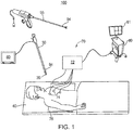
- system 100 suitable for performing laparoscopic surgery on a patient is provided in accordance with an embodiment of the present disclosure.
- system 100 is used to perform one or more diagnostic and/or treatment procedures on a patient supported on an operating table 40.
- system 100 generally includes at least one laparoscope 30, at least one surgical tool 55, monitoring equipment 60, an electromagnetic (EM) tracking system 70, and a computing device 80.
- system 100 may further include a surgical robot (not shown) including one or more robotic arm assemblies and a controller configured to operate the surgical robot.
- laparoscope 30 and/or surgical tool 55 may be coupled to the surgical robot via at least one of the robotic arm assemblies.
- Laparoscope 30 includes a source of illumination and a laparoscopic camera 35 coupled to monitoring equipment 60, for example, a video display, for displaying video images received from camera 35.
- Laparoscope 30 is configured for insertion into the patient's body, e.g. through a surgical incision and/or a laparoscopic port, to provide images of a surgical site inside the patient's body, for example, inside the patient's thoracic cavity. As illustrated in FIG. 1 , the patient is shown laying on operating table 40 with laparoscope 30 and surgical tool 55 positioned for insertion into the patient's body.
- Surgical tool 55 may be any surgical tool usable during laparoscopic surgery, including cutting tools, suction tools, biopsy tools, resection tools, graspers, ablation tools, ligation tools, surgical staplers, ultrasonic and/or electrosurgical vessel sealers, etc.
- EM tracking system 70 may be a six degrees-of-freedom EM tracking system, e.g., similar to those disclosed in U.S. Patent No. 6,188,355 and published PCT Application Nos. WO 00/10456 and WO 01/67035 , entitled “WIRELESS SIX-DEGREE-OF-FREEDOM LOCATOR", filed on December 14, 1998 by Gilboa, the entire contents of each of which is incorporated herein by reference, or any other suitable positioning measuring system, is utilized for performing tracking, although other configurations are also contemplated.
- EM tracking system 70 may be configured for use with laparoscope 30 to track the position of an EM sensor 94 as it moves in conjunction with laparoscope 30 about the patient's body, as detailed below.
- EM tracking system 70 includes a tracking module 72, a plurality of reference sensors 74, and an EM field generator 76. As shown in FIG. 1 , EM field generator 76 is positioned beneath the patient. EM field generator 76 and the plurality of reference sensors 74 are interconnected with tracking module 72, which derives the location of each reference sensor 74 in the six degrees of freedom. One or more of reference sensors 74 are attached to the chest of the patient. The six degrees of freedom coordinates of reference sensors 74 are sent as data to computing device 80, which includes an application 81, where the data from sensors 74 are used to calculate a patient coordinate frame of reference.
- Laparoscope 30 further includes, or has coupled thereto, at least one EM sensor 94 trackable by tracking module 72.
- the location of EM sensor 94, and thus the distal end of laparoscope 30, within an EM field generated by EM field generator 76 can be derived by tracking module 72 and computing device 80.
- Surgical tool 55 may also include, or have coupled thereto, one or more EM sensors 94 to be tracked by tracking module 72 and computing device 80, similar to laparoscope 30.
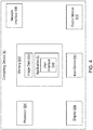
- Computing device 80 includes various software and/or hardware components, such as application 81. As shown in the exemplary embodiment of FIG. 4 , computing device 80 may include memory 502, one or more processors 504, a display 506, a network interface 508, an input device 510, and/or an output module 512. Memory 502 may store application 81 and/or image data 514. Application 81 may include instructions which, when executed by processor 504, cause display 506 to present a user interface 516. Application 81 may also provide the interface between the sensed position of EM sensor 94 and the image and planning data developed in the pathway planning phase.
- Memory 502 may include any non-transitory computer-readable storage media for storing data and/or software that is executable by processor 504 and which controls the operation of computing device 80.
- memory 502 may include one or more solid-state storage devices such as flash memory chips.
- memory 502 may include one or more mass storage devices connected to the processor 504 through a mass storage controller (not shown) and a communications bus (not shown).
- mass storage controller not shown
- communications bus not shown
- computer readable storage media may include non-transitory, volatile and nonvolatile, removable and non-removable media implemented in any method or technology for storage of information, such as computer-readable instructions, data structures, program modules, and/or other data.
- computer-readable storage media may include RAM, ROM, EPROM, EEPROM, flash memory and/or other solid state memory technology, CD-ROM, DVD, Blu-Ray and/or other optical storage, magnetic cassettes, magnetic tape, magnetic disk storage and/or other magnetic storage devices, and/or any other medium which may be used to store the desired information and is accessable by computing device 80.
- Network interface 508 may be configured to connect to a network such as a local area network (LAN) consisting of a wired network and/or a wireless network, a wide area network (WAN), a wireless mobile network, a Bluetooth network, and/or the internet.
- LAN local area network
- WAN wide area network
- wireless mobile network a Bluetooth network
- Input device 510 may be any device by means of which a user may interact with computing device 80, such as, for example, a mouse, keyboard, foot pedal, touch screen, and/or voice interface.
- Output module 512 may include any connectivity port or bus, such as, for example, parallel ports, serial ports, universal serial busses (USB), or any other similar connectivity port known to those skilled in the art.
- USB universal serial busses
- Application 81 may be used to facilitate the various phases of the medical procedure, including generating the aforementioned 3D model, and navigating laparoscope 30 and/or treatment tool 55 to the treatment location.
- computing device 80 utilizes medical image data, such as radiographically obtained computed tomographic (CT), magnetic resonance imaging (MRI), and/or positron emission tomography (PET) image data for generating and viewing the 3D model of the patient's body. While the aforementioned, or any other medical image data known to those skilled in the art, may be used, either individually and/or in combination, the present disclosure will use an CT image data as an example.
- CT computed tomographic
- MRI magnetic resonance imaging
- PET positron emission tomography
- the 3D model may be displayed on a display monitor associated with computing device 80, for example, display 506, and/or in any other suitable fashion.
- various views of the 3D model may be displayed and may be manipulated by a clinician to give the clinician a preferred view of the treatment location.
- the treatment location may be a surgical site where the treatment is to be performed.
- the 3D model may include, among other things, a model airway tree corresponding to the actual airways of the patient's lungs, and showing the various passages, branches, and bifurcations of the patient's actual airway tree.
- the 3D model may include lesions, markers, blood vessels and vascular structures, lymphatic vessels and structures, organs, other physiological structures, and/or a 3D rendering of the pleura and fissures of the lungs.
- Some or all of the aforementioned elements may be selectively displayed, such that the clinician may choose which elements should be displayed when viewing the 3D model.
- application 81 may be configured in various states to display the 3D model in a variety of view modes. For each view of the 3D model, the angle from which the 3D model is displayed may correspond to a view point. The view point may be fixed at a predefined location and/or orientation, or may be adjusted by application 81 and/or the clinician operating computing device 80.
- the systems and methods described in the present disclosure may be used during various medical procedures, including diagnostic and/or treatment procedures performed on various parts and/or organs of the patient's body, such as the lungs, kidneys, spleen, prostate, thyroid, liver, etc.
- various medical procedures including diagnostic and/or treatment procedures performed on various parts and/or organs of the patient's body, such as the lungs, kidneys, spleen, prostate, thyroid, liver, etc.
- the exemplary embodiments described below use the patient's lungs as an example. This is not intended to be limiting, as those skilled in the art will recognize that the same or similar systems and methods as described in the present disclosure may be used during medical procedures performed on various other parts and/or organs of the patient's body.
- the 3D model is registered with the patient's body. This is required because the position of the patient when the CT image data was obtained often does not correspond to the typical position of the patient during a medical procedure.
- an orientation of the patient is identified in the EM field.
- a camera such as laparoscopic camera 35 included in laparoscope 30 along with EM sensor 94, is then used to scan the thoracic area of the patient, typically oriented in a lateral decubitus position. Key information determined from this scan would be the angular rotation of the sagittal plane from the vertical and the curvature or elongation of the chest wall prior to draping the patient.
- the curvature or elongation of the chest wall is detected by image matching algorithms looking for similar structures near the axilla or scapula and the lower extent of the rib cage. This key information may also be approximated by manual input from the clinician, such as via input device 510. This information is particularly important if any portion of the lung anatomy is simulated, as the orientation relative to gravity must be defined.
- This may be performed by any number of means of stitching the images into a 3D surface model, such as 2D image triangulation, time of flight, and/or projected/structured light scans.
- the surface model is then compared with the 3D model constructed from the CT imaging of the lung.
- Edge finding algorithms may be used to compare the various landmarks in the scanned and CT constructed 3D models which may then be used to align the position of those landmarks in the 3D model with the position in the patient's body, thereby completing the initial registration.
- laparoscope 30 and/or surgical tool 55 may also be visualized by using ultrasound imaging.
- An ultrasound sensor (not shown), such as an ultrasound wand, may be used to image the patient's body during the medical procedure to visualize the location of laparoscope 30 and/or surgical tool 55 inside the patient's body.
- the ultrasound sensor may have an EM tracking sensor embedded within or attached to the ultrasound wand, for example, a clip-on sensor or a sticker sensor.
- the ultrasound sensor may be positioned in relation to laparoscope 30 or surgical tool 55 such that laparoscope 30 or surgical tool 55 is at an angle to the ultrasound image plane, thereby enabling the clinician to visualize the spatial relationship of laparoscope 30 or surgical tool 55 with the ultrasound image plane and with objects being imaged.
- EM tracking system 70 may also track the location of the ultrasound sensor.
- one or more ultrasound sensors may be placed inside the patient's body.
- EM tracking system 70 may then track the location of such ultrasound sensors and laparoscope 30 and/or surgical tool 55 inside the patient's body.
- An ultrasound workstation may be used to configure, operate, and view images captured by the ultrasound sensor. Objects such as the target surgical lesion or anatomic features even in the chest wall may be used as landmarks for systematic registration of the scanned and CT generated 3D models.
- FIG. 2 there is shown a flowchart of an exemplary method of controlling images displayed by a medical image viewer based on movement of surgical tools, in accordance with an embodiment of the present disclosure.
- the method described below details an exemplary embodiment wherein laparoscopic thoracic surgery is performed.
- laparoscopic thoracic surgery is performed.
- those skilled in the art will appreciate that the same or similar steps to those described below may also be used in various other medical procedures and/or settings.
- computing device 80 receives image data of the patient's body.
- the image data may be collected by one or more of various imaging modalities, including computed tomography (CT) scans, cone beam computed tomography (CBCT) scans, magnetic resonance imaging (MRI) scans, positron emission tomography (PET) scans, ultrasound scans, X-ray scans, and/or any other relevant imaging modality known to those skilled in the art.
- CT computed tomography
- CBCT cone beam computed tomography
- MRI magnetic resonance imaging
- PET positron emission tomography
- ultrasound scans X-ray scans
- X-ray scans X-ray scans
- the image data may be received in, or converted to, a uniform data format, such as the digital imaging and communications in medicine (DICOM) standard.
- DICOM digital imaging and communications in medicine
- the patient may undergo a CT scan prior to the medical procedure during which CT image data of at least a portion of the patient's body is collected and compiled
- step S304 application 81 processes the received image data to identify landmarks and/or structures, such as the patient's lungs, in the image data.
- the image processing may include automatic and/or user-assisted image analysis to identify the patient's lungs in the image data.
- Various image processing methods may be used, including region growing techniques, as described in in co-pending U.S. Patent Application Publication No. 2016/0038248 , entitled “TREATMENT PROCEDURE PLANNING SYSTEM AND METHOD”, filed on August 10, 2015, by Bharadwaj et al., and co-pending U.S. Patent Application Publication No. 2016/0005193 , entitled “SYSTEM AND METHOD FOR SEGMENTATION OF LUNG”, filed on June 30, 2015, by Markov et al., the contents of both of which are incorporated herein by reference.
- application 81 generates a three-dimensional (3D) model of the patient's lungs.
- the 3D model includes graphical representations of the patient's lungs, showing the locations of the lumens of the bronchial, vascular, and lymphatic trees, as well as the fissures and pleura of the patient's lungs.
- Application 81 may also generate an inflated and/or deflated 3D model of the patient's lungs wherein inflation and/or deflation of some or all areas of the patient's lungs is simulated, based on the needs of the particular surgical procedure being performed.
- the 3D model is registered with the patient's body.
- registration may involve moving laparoscope 30 including EM sensor 94 about the patient's thoracic cavity, tracking the location of EM sensor 94 during such movement, and iteratively updating the 3D model based on the tracked location of EM sensor 94 by comparing the landmarks found in the scanned and CT constructed 3D models to register the two models with each other, as further described above.
- the location, orientation, and direction of movement of one or more tools is determined.
- the term "tool” refers to any instrument inserted into the patient's body which may have an EM sensor 94 attached thereto or incorporated therein. The clinician may select, at the start of the procedure or during the procedure, which EM sensor 94, and thus which tool, should be used for identifying a medical image to be displayed.
- the tool is laparoscope 30 which includes laparoscopic camera 35, as described above with reference to FIG. 1 .
- the tool is a vessel sealer or surgical stapler, such as surgical tool 55.
- the tool includes an EM sensor 94 enabling an EM tracking system 70 to detect the location of the tool inside the patient's body. By tracking successive locations of EM sensor 94, an orientation and direction of movement of the tool may also be determined.
- the tool e.g. laparoscope 30 or surgical tool 55
- the location, orientation, and direction of movement of the tool may be determined based on a pose of the surgical robot.
- the pose of the surgical robot corresponds to the particular location and orientation of each component of the surgical robot at a particular point in time.
- the controller operating the surgical robot will know the location, orientation, and direction of movement of the various components of the surgical robot, including the tools coupled thereto.
- the location, orientation, and direction of movement of any tools coupled to the surgical robot may be determined based on the location, orientation, and direction of movement of the various components of the surgical robot.
- application 81 may identify and select a medical image, such as a 2D slice image, based on the determined location of the tool.
- the 2D slice image may be a CT image from a CT image volume, such as the image data received at step S302.
- the 2D slice image may be a 2D image generated based on the 3D model.
- the 2D slice image is generated based on the image data received at step S302 in a non-orthogonal orientation. That is, the 2D slice image is generated in an orientation different from the axial, saggital, and coronal orientations.
- Application 81 may then, at step S314, cause a display device, such as display 506 ( FIG. 4 ) to display the 2D slice image, as shown in FIG. 3 (described below).
- step S316 application 81 determines whether the medical procedure has been completed. For example, application 81 may receive input from the clinician and/or may determine, based on the detected location of the tools, that the procedure is complete, and thereby end the process. However, if application 81 determines that the procedure is not complete, processing continues to step S318, where application 81 determines whether the location of the tool has changed. If the location of the tool has not changed, processing returns to step S314 where the same 2D slice image previously identified is displayed. However, if application 81 determines that the location of the tool has changed, processing proceeds to step S320, where application 81 determines a new location, orientation, and direction of movement of the tool.
- step S322 application 81 identifies a new 2D slice image based on the new location, orientation, and direction of movement of the tool.
- the new 2D slice image may generated based on the image data received at step S302.
- the direction of movement of the tool is non-orthogonal, that is, the direction of movement of the tool is not along the axial, saggital, or coronal axes.
- the new 2D slice image may be generated in a non-orthogonal orientation. That is, the 2D slice image is generated in an orientation different from the axial, saggital, and coronal orientations.
- Processing then returns to step S314 where the newly identified 2D slice image is displayed. Steps S314 to S322 may be repeated until such time that application 81 determines at step S316 that the procedure is complete.
- FIG. 3 shows an example view of the medical image viewer which may be displayed by the display device.
- the medical image viewer may include a live view 402 from a camera, such as laparoscopic camera 35, inserted in the patient's body, a view 404 of the 3D model including a line 406 on the view 404 of the 3D model which indicates the position and orientation of a slice image 408.
- Slice image 408 may be in a view 410 of the slice image 408, such as a "picture in picture" or an overlay over live view 402.
- View 404 of the 3D model and slice image 408 may selectively be displayed and/or disabled based on the procedure and the clinician's preferences.
Landscapes
- Health & Medical Sciences (AREA)
- Life Sciences & Earth Sciences (AREA)
- Surgery (AREA)
- Engineering & Computer Science (AREA)
- Nuclear Medicine, Radiotherapy & Molecular Imaging (AREA)
- Heart & Thoracic Surgery (AREA)
- Veterinary Medicine (AREA)
- Biomedical Technology (AREA)
- Public Health (AREA)
- Medical Informatics (AREA)
- Molecular Biology (AREA)
- Animal Behavior & Ethology (AREA)
- General Health & Medical Sciences (AREA)
- Pathology (AREA)
- Radiology & Medical Imaging (AREA)
- Biophysics (AREA)
- Physics & Mathematics (AREA)
- Optics & Photonics (AREA)
- Signal Processing (AREA)
- Robotics (AREA)
- Pulmonology (AREA)
- Gynecology & Obstetrics (AREA)
- Oral & Maxillofacial Surgery (AREA)
- Otolaryngology (AREA)
- Physiology (AREA)
- Urology & Nephrology (AREA)
- Human Computer Interaction (AREA)
- Endoscopes (AREA)
- Apparatus For Radiation Diagnosis (AREA)
Applications Claiming Priority (1)
| Application Number | Priority Date | Filing Date | Title |
|---|---|---|---|
| US15/585,592 US11779192B2 (en) | 2017-05-03 | 2017-05-03 | Medical image viewer control from surgeon's camera |
Publications (1)
| Publication Number | Publication Date |
|---|---|
| EP3398552A1 true EP3398552A1 (fr) | 2018-11-07 |
Family
ID=62200234
Family Applications (1)
| Application Number | Title | Priority Date | Filing Date |
|---|---|---|---|
| EP18170432.1A Withdrawn EP3398552A1 (fr) | 2017-05-03 | 2018-05-02 | Commande de visionneuse d'images médicales à partir de la caméra du chirurgien |
Country Status (2)
| Country | Link |
|---|---|
| US (1) | US11779192B2 (fr) |
| EP (1) | EP3398552A1 (fr) |
Cited By (2)
| Publication number | Priority date | Publication date | Assignee | Title |
|---|---|---|---|---|
| EP3690810A1 (fr) * | 2019-01-30 | 2020-08-05 | Covidien LP | Procédé d'affichage d'emplacement de tumeur dans des images endoscopiques |
| EP3689281A1 (fr) * | 2019-02-04 | 2020-08-05 | Covidien LP | Systèmes et procédés pour faciliter la prédiction pré-opératoire d'une fonction de tissu post-opératoire |
Families Citing this family (4)
| Publication number | Priority date | Publication date | Assignee | Title |
|---|---|---|---|---|
| CN111050686B (zh) * | 2017-09-05 | 2023-06-16 | 柯惠Lp公司 | 手术机器人系统的摄像机控制 |
| US10733745B2 (en) * | 2019-01-07 | 2020-08-04 | The University Of North Carolina At Chapel Hill | Methods, systems, and computer readable media for deriving a three-dimensional (3D) textured surface from endoscopic video |
| WO2020177725A1 (fr) * | 2019-03-04 | 2020-09-10 | 杭州三坛医疗科技有限公司 | Procédé de détermination d'un trajet cible |
| US10682108B1 (en) | 2019-07-16 | 2020-06-16 | The University Of North Carolina At Chapel Hill | Methods, systems, and computer readable media for three-dimensional (3D) reconstruction of colonoscopic surfaces for determining missing regions |
Citations (12)
| Publication number | Priority date | Publication date | Assignee | Title |
|---|---|---|---|---|
| EP0920838A2 (fr) * | 1997-12-08 | 1999-06-09 | The Cleveland Clinic Foundation | Dispositif de positionnement |
| WO2000010456A1 (fr) | 1998-08-02 | 2000-03-02 | Super Dimension Ltd. | Systeme de navigation intracorporelle pour applications medicales |
| US6188355B1 (en) | 1997-12-12 | 2001-02-13 | Super Dimension Ltd. | Wireless six-degree-of-freedom locator |
| WO2001067035A1 (fr) | 2000-03-09 | 2001-09-13 | Super Dimension Ltd. | Reperage d'objet au moyen d'un detecteur unique ou d'une paire de detecteurs |
| US20110085720A1 (en) | 2009-05-14 | 2011-04-14 | Superdimension, Ltd. | Automatic Registration Technique |
| US8267853B2 (en) * | 2008-06-23 | 2012-09-18 | Southwest Research Institute | System and method for overlaying ultrasound imagery on a laparoscopic camera display |
| US8554307B2 (en) * | 2010-04-12 | 2013-10-08 | Inneroptic Technology, Inc. | Image annotation in image-guided medical procedures |
| US20140303491A1 (en) * | 2013-04-04 | 2014-10-09 | Children's National Medical Center | Device and method for generating composite images for endoscopic surgery of moving and deformable anatomy |
| US20160005193A1 (en) | 2014-07-02 | 2016-01-07 | Covidien Lp | System and method for segmentation of lung |
| US20160000356A1 (en) | 2014-07-02 | 2016-01-07 | Covidien Lp | Real-time automatic registration feedback |
| US20160038248A1 (en) | 2014-08-11 | 2016-02-11 | Covidien Lp | Treatment procedure planning system and method |
| US20160317229A1 (en) | 2015-04-30 | 2016-11-03 | Covidien Lp | Methods for microwave ablation planning and procedure |
Family Cites Families (28)
| Publication number | Priority date | Publication date | Assignee | Title |
|---|---|---|---|---|
| US20020009215A1 (en) * | 2000-01-18 | 2002-01-24 | Arch Development Corporation | Automated method and system for the segmentation of lung regions in computed tomography scans |
| US7336809B2 (en) * | 2001-11-23 | 2008-02-26 | R2 Technology, Inc. | Segmentation in medical images |
| US10555775B2 (en) * | 2005-05-16 | 2020-02-11 | Intuitive Surgical Operations, Inc. | Methods and system for performing 3-D tool tracking by fusion of sensor and/or camera derived data during minimally invasive robotic surgery |
| ATE540634T1 (de) * | 2005-06-06 | 2012-01-15 | Intuitive Surgical Operations | Laparoskopisches ultraschall-robotersystem für chirurgische zwecke |
| US7824328B2 (en) * | 2006-09-18 | 2010-11-02 | Stryker Corporation | Method and apparatus for tracking a surgical instrument during surgery |
| US8248413B2 (en) * | 2006-09-18 | 2012-08-21 | Stryker Corporation | Visual navigation system for endoscopic surgery |
| US8248414B2 (en) * | 2006-09-18 | 2012-08-21 | Stryker Corporation | Multi-dimensional navigation of endoscopic video |
| US20080071141A1 (en) * | 2006-09-18 | 2008-03-20 | Abhisuek Gattani | Method and apparatus for measuring attributes of an anatomical feature during a medical procedure |
| WO2008125910A2 (fr) * | 2006-11-10 | 2008-10-23 | Superdimension, Ltd. | Technique de guidage adaptative destinée à guider un cathéter dans une cavité ou un canal corporel |
| IL188569A (en) * | 2007-01-17 | 2014-05-28 | Mediguide Ltd | Method and system for coordinating a 3D image coordinate system with a medical position coordinate system and a 2D image coordinate system |
| US8858436B2 (en) * | 2008-11-12 | 2014-10-14 | Sonosite, Inc. | Systems and methods to identify interventional instruments |
| US8690776B2 (en) * | 2009-02-17 | 2014-04-08 | Inneroptic Technology, Inc. | Systems, methods, apparatuses, and computer-readable media for image guided surgery |
| JP5836267B2 (ja) * | 2009-05-18 | 2015-12-24 | コーニンクレッカ フィリップス エヌ ヴェKoninklijke Philips N.V. | 電磁追跡内視鏡システムのためのマーカーなし追跡の位置合わせおよび較正のための方法およびシステム |
| US10069668B2 (en) * | 2009-12-31 | 2018-09-04 | Mediguide Ltd. | Compensation of motion in a moving organ using an internal position reference sensor |
| WO2013116240A1 (fr) * | 2012-01-30 | 2013-08-08 | Inneroptic Technology, Inc. | Guidage de dispositifs médicaux multiples |
| CN103561628B (zh) * | 2012-03-06 | 2016-08-17 | 奥林巴斯株式会社 | 内窥镜系统 |
| US20130250081A1 (en) * | 2012-03-21 | 2013-09-26 | Covidien Lp | System and method for determining camera angles by using virtual planes derived from actual images |
| WO2013164826A1 (fr) * | 2012-05-04 | 2013-11-07 | Given Imaging Ltd. | Système et procédé de navigation automatique d'une capsule basé sur un flux d'images capturé in vivo |
| DE102012220115A1 (de) * | 2012-11-05 | 2014-05-22 | Fraunhofer-Gesellschaft zur Förderung der angewandten Forschung e.V. | Bildgebendes System, Operationsvorrichtung mit dem bildgebenden System und Verfahren zur Bildgebung |
| HK1216049A1 (zh) * | 2012-11-23 | 2016-10-07 | Cadens Medical Imaging Inc. | 为用户显示第一绘制投影和第二绘制投影之间的过渡的方法和系统 |
| US10687909B2 (en) * | 2014-01-24 | 2020-06-23 | Koninklijke Philips N.V. | Robotic control of imaging devices with optical shape sensing |
| US20170105802A1 (en) * | 2014-03-27 | 2017-04-20 | Bresmedical Pty Limited | Computer aided surgical navigation and planning in implantology |
| US11188285B2 (en) * | 2014-07-02 | 2021-11-30 | Covidien Lp | Intelligent display |
| US9770216B2 (en) * | 2014-07-02 | 2017-09-26 | Covidien Lp | System and method for navigating within the lung |
| US9901406B2 (en) * | 2014-10-02 | 2018-02-27 | Inneroptic Technology, Inc. | Affected region display associated with a medical device |
| US10188467B2 (en) * | 2014-12-12 | 2019-01-29 | Inneroptic Technology, Inc. | Surgical guidance intersection display |
| CN108472095B (zh) * | 2015-12-29 | 2021-11-02 | 皇家飞利浦有限公司 | 用于机器人外科手术的使用虚拟现实设备的系统、控制器和方法 |
| US10278778B2 (en) * | 2016-10-27 | 2019-05-07 | Inneroptic Technology, Inc. | Medical device navigation using a virtual 3D space |
-
2017
- 2017-05-03 US US15/585,592 patent/US11779192B2/en active Active
-
2018
- 2018-05-02 EP EP18170432.1A patent/EP3398552A1/fr not_active Withdrawn
Patent Citations (12)
| Publication number | Priority date | Publication date | Assignee | Title |
|---|---|---|---|---|
| EP0920838A2 (fr) * | 1997-12-08 | 1999-06-09 | The Cleveland Clinic Foundation | Dispositif de positionnement |
| US6188355B1 (en) | 1997-12-12 | 2001-02-13 | Super Dimension Ltd. | Wireless six-degree-of-freedom locator |
| WO2000010456A1 (fr) | 1998-08-02 | 2000-03-02 | Super Dimension Ltd. | Systeme de navigation intracorporelle pour applications medicales |
| WO2001067035A1 (fr) | 2000-03-09 | 2001-09-13 | Super Dimension Ltd. | Reperage d'objet au moyen d'un detecteur unique ou d'une paire de detecteurs |
| US8267853B2 (en) * | 2008-06-23 | 2012-09-18 | Southwest Research Institute | System and method for overlaying ultrasound imagery on a laparoscopic camera display |
| US20110085720A1 (en) | 2009-05-14 | 2011-04-14 | Superdimension, Ltd. | Automatic Registration Technique |
| US8554307B2 (en) * | 2010-04-12 | 2013-10-08 | Inneroptic Technology, Inc. | Image annotation in image-guided medical procedures |
| US20140303491A1 (en) * | 2013-04-04 | 2014-10-09 | Children's National Medical Center | Device and method for generating composite images for endoscopic surgery of moving and deformable anatomy |
| US20160005193A1 (en) | 2014-07-02 | 2016-01-07 | Covidien Lp | System and method for segmentation of lung |
| US20160000356A1 (en) | 2014-07-02 | 2016-01-07 | Covidien Lp | Real-time automatic registration feedback |
| US20160038248A1 (en) | 2014-08-11 | 2016-02-11 | Covidien Lp | Treatment procedure planning system and method |
| US20160317229A1 (en) | 2015-04-30 | 2016-11-03 | Covidien Lp | Methods for microwave ablation planning and procedure |
Non-Patent Citations (1)
| Title |
|---|
| LANGØ ET AL: "Navigation in laparoscopy -Prototype research platform for improved image- guided surgery", MINIMALLY INVASIVE THERAPY, vol. 17, no. 1, 29 November 2007 (2007-11-29), pages 17 - 33, XP055804097, DOI: 10.1080/13645700701797879.Source: * |
Cited By (5)
| Publication number | Priority date | Publication date | Assignee | Title |
|---|---|---|---|---|
| EP3690810A1 (fr) * | 2019-01-30 | 2020-08-05 | Covidien LP | Procédé d'affichage d'emplacement de tumeur dans des images endoscopiques |
| CN111494006A (zh) * | 2019-01-30 | 2020-08-07 | 柯惠有限合伙公司 | 用于在内窥镜图像中显示肿瘤位置的方法 |
| EP3689281A1 (fr) * | 2019-02-04 | 2020-08-05 | Covidien LP | Systèmes et procédés pour faciliter la prédiction pré-opératoire d'une fonction de tissu post-opératoire |
| US11744643B2 (en) | 2019-02-04 | 2023-09-05 | Covidien Lp | Systems and methods facilitating pre-operative prediction of post-operative tissue function |
| US12167893B2 (en) | 2019-02-04 | 2024-12-17 | Covidien Lp | Systems and methods facilitating pre-operative prediction of post-operative tissue function |
Also Published As
| Publication number | Publication date |
|---|---|
| US20180317740A1 (en) | 2018-11-08 |
| US11779192B2 (en) | 2023-10-10 |
Similar Documents
| Publication | Publication Date | Title |
|---|---|---|
| US11622815B2 (en) | Systems and methods for providing proximity awareness to pleural boundaries, vascular structures, and other critical intra-thoracic structures during electromagnetic navigation bronchoscopy | |
| US12064280B2 (en) | System and method for identifying and marking a target in a fluoroscopic three-dimensional reconstruction | |
| CN112386336B (zh) | 用于进行初始配准的荧光-ct成像的系统和方法 | |
| US11341692B2 (en) | System and method for identifying, marking and navigating to a target using real time two dimensional fluoroscopic data | |
| US10238455B2 (en) | Pathway planning for use with a navigation planning and procedure system | |
| EP3366254B1 (fr) | Intégration de multiples sources de données pour localisation et navigation | |
| US11737827B2 (en) | Pathway planning for use with a navigation planning and procedure system | |
| US11779192B2 (en) | Medical image viewer control from surgeon's camera | |
| WO2026083240A1 (fr) | Représentation d'une anatomie cible cachée sur une imagerie en direct |
Legal Events
| Date | Code | Title | Description |
|---|---|---|---|
| PUAI | Public reference made under article 153(3) epc to a published international application that has entered the european phase |
Free format text: ORIGINAL CODE: 0009012 |
|
| STAA | Information on the status of an ep patent application or granted ep patent |
Free format text: STATUS: REQUEST FOR EXAMINATION WAS MADE |
|
| 17P | Request for examination filed |
Effective date: 20180502 |
|
| AK | Designated contracting states |
Kind code of ref document: A1 Designated state(s): AL AT BE BG CH CY CZ DE DK EE ES FI FR GB GR HR HU IE IS IT LI LT LU LV MC MK MT NL NO PL PT RO RS SE SI SK SM TR |
|
| AX | Request for extension of the european patent |
Extension state: BA ME |
|
| RBV | Designated contracting states (corrected) |
Designated state(s): AL AT BE BG CH CY CZ DE DK EE ES FI FR GB GR HR HU IE IS IT LI LT LU LV MC MK MT NL NO PL PT RO RS SE SI SK SM TR |
|
| STAA | Information on the status of an ep patent application or granted ep patent |
Free format text: STATUS: EXAMINATION IS IN PROGRESS |
|
| 17Q | First examination report despatched |
Effective date: 20210518 |
|
| STAA | Information on the status of an ep patent application or granted ep patent |
Free format text: STATUS: THE APPLICATION IS DEEMED TO BE WITHDRAWN |
|
| 18D | Application deemed to be withdrawn |
Effective date: 20231003 |