EP3398782A1 - Système d'encrage pour encrer un cylindre d'impression en creux d'une presse d'impression en creux, presse d'impression en creux le comprenant et procédé d'encrage d'un tel cylindre d'impression en creux - Google Patents
Système d'encrage pour encrer un cylindre d'impression en creux d'une presse d'impression en creux, presse d'impression en creux le comprenant et procédé d'encrage d'un tel cylindre d'impression en creux Download PDFInfo
- Publication number
- EP3398782A1 EP3398782A1 EP17169509.1A EP17169509A EP3398782A1 EP 3398782 A1 EP3398782 A1 EP 3398782A1 EP 17169509 A EP17169509 A EP 17169509A EP 3398782 A1 EP3398782 A1 EP 3398782A1
- Authority
- EP
- European Patent Office
- Prior art keywords
- inking
- ink
- intaglio printing
- cylinder
- selective
- Prior art date
- Legal status (The legal status is an assumption and is not a legal conclusion. Google has not performed a legal analysis and makes no representation as to the accuracy of the status listed.)
- Withdrawn
Links
- 238000007639 printing Methods 0.000 title claims abstract description 217
- 238000000034 method Methods 0.000 title claims description 15
- 230000008569 process Effects 0.000 title claims description 13
- 238000012546 transfer Methods 0.000 claims abstract description 49
- 239000011248 coating agent Substances 0.000 claims abstract description 46
- 238000000576 coating method Methods 0.000 claims abstract description 46
- 239000005871 repellent Substances 0.000 claims abstract description 39
- 238000012423 maintenance Methods 0.000 claims description 21
- 239000000976 ink Substances 0.000 description 233
- 238000007689 inspection Methods 0.000 description 11
- 238000004140 cleaning Methods 0.000 description 6
- 230000003287 optical effect Effects 0.000 description 5
- 238000001035 drying Methods 0.000 description 4
- 238000000608 laser ablation Methods 0.000 description 4
- 238000004519 manufacturing process Methods 0.000 description 4
- 238000002679 ablation Methods 0.000 description 3
- XAGFODPZIPBFFR-UHFFFAOYSA-N aluminium Chemical compound [Al] XAGFODPZIPBFFR-UHFFFAOYSA-N 0.000 description 3
- 229910052782 aluminium Inorganic materials 0.000 description 3
- 239000004411 aluminium Substances 0.000 description 3
- 238000013461 design Methods 0.000 description 3
- 230000001747 exhibiting effect Effects 0.000 description 3
- 239000000463 material Substances 0.000 description 3
- 238000011109 contamination Methods 0.000 description 2
- 238000010147 laser engraving Methods 0.000 description 2
- 239000012858 resilient material Substances 0.000 description 2
- 101150097169 RBBP8 gene Proteins 0.000 description 1
- 229910000831 Steel Inorganic materials 0.000 description 1
- 239000003086 colorant Substances 0.000 description 1
- 230000001419 dependent effect Effects 0.000 description 1
- 238000007644 letterpress printing Methods 0.000 description 1
- 230000007246 mechanism Effects 0.000 description 1
- 238000012986 modification Methods 0.000 description 1
- 230000004048 modification Effects 0.000 description 1
- 238000007645 offset printing Methods 0.000 description 1
- 238000012545 processing Methods 0.000 description 1
- 238000005096 rolling process Methods 0.000 description 1
- 239000007779 soft material Substances 0.000 description 1
- 239000007787 solid Substances 0.000 description 1
- 239000010959 steel Substances 0.000 description 1
- 239000000126 substance Substances 0.000 description 1
- 238000011144 upstream manufacturing Methods 0.000 description 1
- 238000005406 washing Methods 0.000 description 1
- 239000002699 waste material Substances 0.000 description 1
Images






Classifications
-
- B—PERFORMING OPERATIONS; TRANSPORTING
- B41—PRINTING; LINING MACHINES; TYPEWRITERS; STAMPS
- B41F—PRINTING MACHINES OR PRESSES
- B41F31/00—Inking arrangements or devices
- B41F31/18—Inking arrangements or devices for inking selected parts of printing formes
-
- B—PERFORMING OPERATIONS; TRANSPORTING
- B41—PRINTING; LINING MACHINES; TYPEWRITERS; STAMPS
- B41F—PRINTING MACHINES OR PRESSES
- B41F31/00—Inking arrangements or devices
- B41F31/02—Ducts, containers, supply or metering devices
- B41F31/04—Ducts, containers, supply or metering devices with duct-blades or like metering devices
-
- B—PERFORMING OPERATIONS; TRANSPORTING
- B41—PRINTING; LINING MACHINES; TYPEWRITERS; STAMPS
- B41F—PRINTING MACHINES OR PRESSES
- B41F31/00—Inking arrangements or devices
- B41F31/26—Construction of inking rollers
-
- B—PERFORMING OPERATIONS; TRANSPORTING
- B41—PRINTING; LINING MACHINES; TYPEWRITERS; STAMPS
- B41F—PRINTING MACHINES OR PRESSES
- B41F9/00—Rotary intaglio printing presses
- B41F9/06—Details
- B41F9/061—Inking devices
-
- B—PERFORMING OPERATIONS; TRANSPORTING
- B41—PRINTING; LINING MACHINES; TYPEWRITERS; STAMPS
- B41F—PRINTING MACHINES OR PRESSES
- B41F9/00—Rotary intaglio printing presses
- B41F9/06—Details
- B41F9/061—Inking devices
- B41F9/063—Using inking rollers
-
- B—PERFORMING OPERATIONS; TRANSPORTING
- B41—PRINTING; LINING MACHINES; TYPEWRITERS; STAMPS
- B41F—PRINTING MACHINES OR PRESSES
- B41F9/00—Rotary intaglio printing presses
- B41F9/06—Details
- B41F9/061—Inking devices
- B41F9/065—Using inking rails
Definitions
- the present invention generally relates to systems and methods of inking of an intaglio printing cylinder of an intaglio printing press, which intaglio printing cylinder carries one or more intaglio printing mediums. More precisely, the invention relates to various embodiments of an inking system for inking such an intaglio printing cylinder, an intaglio printing press comprising such an inking system and a process of inking such an intaglio printing cylinder.
- Intaglio printing presses are already known in the art, for instance from Swiss Patent No. CH 685 380 A5 , European Patent Publications Nos. EP 0 406 157 A1 , EP 0 415 881 A2 , EP 0 563 007 A1 , EP 0 873 866 A1 , and International Publications Nos. WO 03/047862 A1 , WO 2005/077656 A1 , WO 2008/146193 A1 , WO 2011/077348 A1 , WO 2011/077350 A1 , WO 2011/077351 A1 , WO 2013/153519 A2 , all assigned to the instant Applicant.
- inking of the plate cylinder carrying the intaglio printing plate(s) is typically carried out by means of a plurality of inking devices that cooperate either directly with the plate cylinder or indirectly, via an ink collecting cylinder (also referred to in the art as "Orlof" cylinder) that collects ink from multiple inking devices.
- an ink collecting cylinder also referred to in the art as "Orlof" cylinder
- Each such inking devices comprises a chablon cylinder that cooperates either with the plate cylinder or the ink collecting cylinder (if present), which chablon cylinder carries a chablon plate comprising relief portions corresponding to engraved areas of the intaglio printing plates that are to be inked with a given ink supplied by an associated inking unit placed upstream of the chablon cylinder.
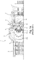
- FIGS 1 a and 1 b schematically illustrate a known intaglio printing press as for instance disclosed in International Publication No. WO 2013/153519 A2 , which printing press is generally designated by reference numeral 1.
- Figure 1a shows a sheet-fed intaglio printing press 1 comprising a sheet feeder 2 for feeding sheets to be printed, an intaglio printing unit 3 for printing the sheets, and a sheet delivery unit 4 for collecting the freshly-printed sheets.
- the intaglio printing unit 3 includes an impression cylinder 7, a plate cylinder 8 acting as intaglio printing cylinder (in this example, the plate cylinder 8 is a three-segment plate cylinder carrying three intaglio printing plates 8a, 8b, 8c), an inking system comprising an ink collecting cylinder, or Orlof cylinder, 9 (here a three-segment blanket cylinder carrying a corresponding number of blankets) for inking the surface of the intaglio printing plates 8a, 8b, 8c carried by the plate cylinder 8 and an ink wiping system 10 for wiping the inked surface of the intaglio printing plates 8a, 8b, 8c carried by the plate cylinder 8 prior to printing of the sheets.
- the sheets are fed from the sheet feeder 2 onto a feeder table and then onto the impression cylinder 7.
- the sheets are then carried by the impression cylinder 7 to the printing nip between the impression cylinder 7 and the plate cylinder 8 where intaglio printing is performed.
- the sheets are transferred away from the impression cylinder 7 for conveyance by a sheet transporting system 11 in order to be delivered to the delivery unit 4.
- the sheet transporting system 11 conventionally comprises a sheet conveyor system with a pair of endless chains driving a plurality of spaced-apart gripper bars for holding a leading edge of the sheets (the freshly-printed side of the sheets being oriented downwards on their way to the delivery unit 4), sheets being transferred in succession to a corresponding one of the gripper bars.
- the optical inspection system 5 is advantageously an inspection system as disclosed in International Publication No. WO 2011/161656 A1 (which publication is incorporated herein by reference in its entirety), which inspection system 5 comprises a transfer mechanism and an inspection drum located at the transfer section between the impression cylinder 7 and chain wheels of the sheet transporting system 11.
- the optical inspection system 5 could alternatively be an inspection system placed along the path of the sheet transporting system 11 as described in International Publications Nos. WO 97/36813 A1 , WO 97/37329 A1 , and WO 03/070465 A1 .
- Such inspection systems are in particular marketed by the Applicant under the product designation NotaSave®.
- the printed sheets are preferably transported in front of a drying or curing unit 6 disposed after the inspection system 5 along the transport path of the sheet transporting system 11. Drying or curing could possibly be performed prior to the optical inspection of the sheets.
- Figure 1b is a schematic view of the intaglio printing unit 3 of the intaglio printing press 1 of Figure 1 a.
- the intaglio printing unit 3 basically includes the impression cylinder 7, the plate cylinder 8 with its intaglio printing plates 8a, 8b, 8c, the inking system with its ink collecting cylinder 9, and the ink wiping system 10.
- the inking system comprises in this example five inking devices 90, all of which cooperate with the ink collecting cylinder 9 that contacts the plate cylinder 8. It will be understood that the illustrated inking system is adapted for indirect inking of the plate cylinder 8, i.e. inking of the intaglio printing plates 8a, 8b, 8c via the ink collecting cylinder 9.
- the inking devices 90 each include an ink duct comprising a duct roller 91 cooperating in this example with a pair of ink application rollers 92. Each pair of ink application rollers 92 in turn inks a corresponding chablon cylinder 93 which is in contact with the ink collecting cylinder 9.
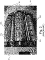
- each chablon cylinder 93 carries a chablon plate 93a (also referred to as a "poly-chablon plate” or “stencil plate”) that is structured so as to exhibit relief portions 93A corresponding to the areas of the intaglio printing plates 8a, 8b, 8c intended to receive the inks in the corresponding colours supplied by the respective inking units 91/92 (see also the photographic illustration of Figure 2 ).
- each chablon plate 93a is functionally equivalent to a letterpress plate, with the relief portions 93A acting as ink transfer portions.
- the impression cylinder 7 and plate cylinder 8 are both supported in a stationary (main) frame 50 of the printing press 1.
- the inking devices 90 (including the duct roller 91 and ink application rollers 92) are supported in a mobile inking carriage 52, while the ink collecting cylinder 9 and chablon cylinders 93 are supported in an intermediate carriage 51 located between the inking carriage 52 and the stationary frame 50. Both the inking carriage 51 and the intermediate carriage 52 are advantageously suspended under supporting rails.
- Figure 2 shows three of the chablon cylinders 93 mounted in the intermediate carriage 51, with the inking carriage 52 (not visible in Figure 2 ) being moved to a retracted position (as schematically illustrated by dashed lines in Figure 1 a) .
- the ink wiping system 10 typically comprises a wiping tank, a wiping roller assembly supported on and partly located in the wiping tank and contacting the plate cylinder 8, cleaning means for removing wiped ink residues from the surface of the wiping roller assembly using a wiping solution that is sprayed or otherwise applied onto the surface of the wiping roller assembly, and a drying blade contacting the surface of the wiping roller assembly for removing wiping solution residues from the surface of the wiping roller assembly.
- a particularly suitable solution for the ink wiping system 10 is disclosed in International Publications Nos. WO 2007/116353 A1 and WO 2013/132471 A1 , which publications are incorporated herein by reference in their entirety.
- the chablon plates 93a typically comprise an outer layer acting as ink transfer layer, which is made of a relatively soft and resilient material (such as a light sensitive photopolymer layer bonded to a steel base plate) that is structured to form the relief portions 93A that cover the relevant areas of the intaglio printing plates to be inked with the desired ink.
- a relatively soft and resilient material such as a light sensitive photopolymer layer bonded to a steel base plate
- Such chablon plates 93a are for instance marketed by company Flint Group under the product designation nyloprint® (in particular nyloprint® WS 230 S or WS 230 Digital stencil plates) and are typically structured by exposure through a laser-ablatable mask (LAM) layer that has been removed (namely ablated by laser) in the portions that are to remain as the desired relief portions 93A after exposure to light and subsequent washing of the unexposed photopolymer layer.
- the resulting relief portions 93A are typically rather simple and basically exhibit a continuous surface where ink is to be transferred as illustrated for instance in the photographic illustration of Figure 2 .
- the relief portions 93A Due to the relatively soft and resilient nature of the material forming the relief portions 93A, it is typically not possible to structure the relief portions 93A of the chablon plates 93a so as to exhibit very fine structures. The resolution of the chablon plates is therefore limited and the relief portions 93A typically restricted to rather crudely-defined surfaces that only vaguely reflect the engraved areas to be inked on the intaglio printing plates.
- British Patent No. GB 987,102 discloses an old concept of an intaglio printing press where the plate cylinder acting as intaglio printing cylinder is inked by means of multiple inking devices, each comprising an ink fountain supplying ink to a duct roller, which transfers the ink to an inking roller cooperating with the plate cylinder via an intermediate transfer roller and a so-called "partial-image cylinder" which rotates in contact with the intermediate ink transfer roller and the inking roller.
- the inking roller which likewise consists of or is coated with a resilient material
- the partial-image cylinder is made of a hard (e.g. metallic) material that is structured to exhibit relief portions precisely matching the delineation of the engraved areas of the intaglio printing plates that are to be inked in the relevant ink.
- GB 987,102 also contemplates to employ ink-repelling means of the type used for lithographic printing processes as a way to carry out the selective transfer of ink by means of the partial-image cylinder.
- a general aim of the invention is therefore to provide an improved solution for inking an intaglio printing cylinder of an intaglio printing press.
- a further aim of the invention is to provide such a solution that achieves a more accurate inking of the intaglio printing mediums carried by the intaglio printing cylinder and, therefore, reduces ink consumption.
- Yet another aim of the invention is to provide such a solution that does not compromise accessibility to and maintenance of the relevant components of the inking system.
- an inking system for inking an intaglio printing cylinder of an intaglio printing press, which intaglio printing cylinder carries one or more intaglio printing mediums, the inking system comprising an ink collecting cylinder designed to cooperate with the intaglio printing cylinder and to collect ink patterns from a plurality of inking devices that are distributed about a portion of the circumference of the ink collecting cylinder, wherein at least one of the inking devices, preferably each inking device, comprises a selective inking cylinder cooperating with the ink collecting cylinder and carrying a selective inking plate, which selective inking plate receives ink supplied by an associated inking unit.
- This selective inking plate comprises a coating that is selectively structured to exhibit ink-repellent portions and perform selective transfer of ink at locations corresponding to engraved areas of the one or more intaglio printing mediums that are to be inked with the ink supplied by the associated inking unit.
- an inking system for inking an intaglio printing cylinder of an intaglio printing press, which intaglio printing cylinder carries one or more intaglio printing mediums, the inking system comprising a plurality of inking devices that are distributed about a portion of the circumference of the intaglio printing cylinder, each inking device comprising a chablon cylinder cooperating with the intaglio printing cylinder and carrying a chablon plate, which chablon plate, receives ink supplied by an associated inking unit.
- Each chablon plate is a relief plate comprising relief portions corresponding to engraved areas of the one or more intaglio printing mediums that are to be inked with the ink supplied by the associated inking unit.
- at least one of the inking devices preferably each inking device, further comprises a selective inking cylinder interposed between the chablon cylinder and the associated inking unit, which selective inking cylinder carries a selective inking plate comprising a coating that is selectively structured to exhibit ink-repellent portions and perform selective transfer of ink at locations corresponding to engraved areas of the one or more intaglio printing mediums that are to be inked with the ink supplied by the associated inking unit.
- an inking system for inking an intaglio printing cylinder of an intaglio printing press, which intaglio printing cylinder carries one or more intaglio printing mediums, the inking system comprising an ink collecting cylinder designed to cooperate with the intaglio printing cylinder and to collect ink patterns from a plurality of inking devices that are distributed about a portion of the circumference of the ink collecting cylinder, each inking device comprising a chablon cylinder cooperating with the ink collecting cylinder and carrying a chablon plate, which chablon plate receives ink supplied by an associated inking unit.
- Each chablon plate (99a) is a relief plate comprising relief portions corresponding to engraved areas of the one or more intaglio printing mediums that are to be inked with the ink supplied by the associated inking unit.
- at least one of the inking devices preferably each inking device, further comprises a selective inking cylinder interposed between the chablon cylinder and the associated inking unit, which selective inking cylinder carries a selective inking plate comprising a coating that is selectively structured to exhibit ink-repellent portions and perform selective transfer of ink at locations corresponding to engraved areas of the one or more intaglio printing mediums that are to be inked with the ink supplied by the associated inking unit.
- the selective transfer of ink is performed indirectly from the selective inking cylinder to the one or more intaglio printing mediums via an ink collecting cylinder and/or via a chablon cylinder carrying a chablon plate comprising relief portions corresponding to engraved areas of the one or more intaglio printing mediums that are to be inked with the ink supplied by the associated inking unit.
- the selective inking plate guarantees optimal accuracy of the inking as the coating can be structured so as to accurately reflect the relevant engraved areas on the intaglio printing plate(s). This leads in turn to a reduced ink consumption.
- the aforementioned coating is preferably an ink-repellent coating that is formed on top of an ink-accepting layer or base, which ink-repellent coating is selectively removed, especially laser-ablated, to expose the underlying ink-accepting layer or base at the locations where ink is to be selectively transferred.
- the coating could be an ink-accepting coating formed on top of an ink-repellent layer or base, which ink-accepting coating is selectively removed, especially laser-ablated, to expose the underlying ink-repellent layer or base and form the ink-repellent portions outside of the locations where ink is to be selectively transferred.
- the selective inking plate could in particular be a plate exhibiting substantially no relief, which is achievable thanks to a coating exhibiting a thickness of the order of a few microns only.
- the inking unit supplying ink to the selective inking plate could advantageously be designed as a short inking unit comprising an ink duct with a duct roller inking the selective inking plate via a pair of ink application rollers.
- the inking unit supplying ink to the selective inking plate could likewise be designed as a short inking unit comprising an ink duct with a duct roller inking the selective inking plate.
- the duct roller could furthermore be provided with engravings corresponding to engraved areas of the one or more intaglio printing mediums that are to be inked with the ink supplied by the inking unit.
- the inking unit supplying ink to the selective inking plate could be designed as a long inking unit comprising an ink duct with a duct roller inking the selective inking plate via a plurality of ink transfer rollers.
- each inking unit could further comprises a vibrator roller interposed between the duct roller and a first one of the ink transfer rollers.
- the aforementioned ink ducts could each be designed as an ink fountain with an ink fountain blade cooperating with the duct roller.
- an intaglio printing press comprising the aforementioned inking system, as well as various embodiments where the inking units, selective inking cylinder(s) and chablon cylinder(s), if present, are located and supported in one or more carriages that can each be retracted during maintenance operations, which facilitates access to the relevant parts and components of the inking system.
- a process of inking an intaglio printing cylinder of an intaglio printing press which intaglio printing cylinder carries one or more intaglio printing mediums, the process including inking the one or more intaglio printing mediums by means of a plurality of inking devices, wherein the process includes a selective transfer of ink to the one or more intaglio printing mediums by means of a selective inking cylinder provided in at least one of the inking devices, preferably in each of the inking devices, which selective inking cylinder carries a selective inking plate receiving ink supplied by an associated inking unit.
- the selective inking plate likewise comprises a coating that is selectively structured to exhibit ink-repellent portions and perform selective transfer of ink at locations corresponding to engraved areas of the one or more intaglio printing mediums that are to be inked with the ink supplied by the associated inking unit.
- This selective transfer of ink is once again performed indirectly from the selective inking cylinder to the one or more intaglio printing mediums via an ink collecting cylinder and/or via a chablon cylinder carrying a chablon plate comprising relief portions corresponding to engraved areas of the one or more intaglio printing mediums that are to be inked with the ink supplied by the associated inking unit.
- the present invention will be described in the particular context of an application to a sheet-fed intaglio printing press as used for the production of banknotes and like security documents. It should however be appreciated that the invention is generally applicable to any intaglio printing press comprising an intaglio printing cylinder carrying one or more intaglio printing mediums on its circumference. This includes in particular web-fed intaglio printing presses, as for instance disclosed in European Patent Publication No. EP 0 415 881 A2 or International Publication No. WO 2004/026580 A1 .
- intaglio printing cylinder designates any cylinder carrying one or more intaglio printing mediums, which intaglio printing mediums are each provided with engraved areas (or “intaglio patterns") that one wishes to supply with ink.
- This in particular includes cylinders adapted to receive a removable intaglio printing sleeve or, as is now more common in the art, a plate cylinder carrying one or more intaglio printing plates.
- the intaglio printing cylinder is a plate cylinder carrying several (namely three) intaglio printing plates on its circumference.
- chablon cylinder is to be understood as designating a cylinder carrying a chablon plate with raised portions whose purpose is to selectively transfer ink patterns to the circumference of a downstream-located ink-receiving cylinder.
- the expression "ink collecting cylinder” designates within the scope of the present invention a cylinder whose purpose is to collect inks from multiple inking devices before transferring the resulting multicolour pattern of inks onto the intaglio printing cylinder.
- the expression “Orlof cylinder” is also typically used as an equivalent to the expression “ink collecting cylinder”.
- selective inking cylinder is to be understood as designating a cylinder carrying a selective inking plate in accordance with the present invention, which "selective inking cylinder” is understood to be distinct from the aforementioned “chablon cylinder”.
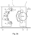
- Figures 3a to 3c schematically illustrate an intaglio printing press comprising an inking system in accordance with a first embodiment of the invention, which intaglio printing press is generally designated by reference numeral 1 I .
- Only the relevant components of the inking system are illustrated in Figures 3a to 3c , including an ink collecting cylinder 9 designed to cooperate with the plate cylinder 8 of the printing unit 3 I of the press and to collect inks from multiple inking devices 95 that are distributed about a portion of the circumference of the ink collecting cylinder 9.
- the configuration of the printing unit 3 I shown in Figures 3a to 3c is basically similar to that of the printing unit 3 shown in Figures 1 and 2 except for the inking system which is different.
- the inking system consists of elements designated by reference numerals 9 and 95 to 98, and includes the ink collecting cylinder 9 collecting ink patterns from a plurality of (namely five) inking devices 95 that are distributed about a portion of the circumference of the ink collecting cylinder 9. Furthermore, at least one of the inking devices 95 (preferably each inking device 95 as illustrated in Figures 3a to 3c ) comprises a selective inking cylinder 98 that cooperates with the ink collecting cylinder 9.
- the selective inking cylinder 98 is a one-segment cylinder whose diameter is one third of that of the associated plate cylinder 8 and ink collecting cylinder 9.
- This selective inking cylinder 98 carries a selective inking plate, designated by reference 90a, which selective inking plate 90a receives ink supplied by an associated inking unit 96/96a/97.
- This inking unit is basically similar to the inking unit 91/92 shown in Figure 1b and is designed as a short inking unit comprising an ink duct 96, 96a with a duct roller 96 supplying ink to the associated selective inking cylinder 98 via a pair of ink application rollers 97.
- the ink duct is here designed as an ink fountain with an ink fountain blade 96a cooperating with the duct roller 96 so as to form an ink reservoir between the ink fountain blade 96a and a portion of the circumference of the duct roller 96.
- the selective inking plate 90a carried by each selective inking cylinder 98 comprises a coating that is selectively structured to exhibit ink-repellent portions and perform selective transfer of ink at locations corresponding to engraved areas of the one or more intaglio printing plates 8a, 8b, 8c (or like intaglio printing mediums) that are to be inked with the ink supplied by the associated inking unit 96/96a/97.
- a preferred solution consists in using an ink-repellent coating that is formed on top of an ink-accepting layer or base, which ink-repellent coating is selectively removed to expose the underlying ink-accepting layer or base at the locations where ink is to be selectively transferred.
- the selective inking plate 90a may consist of an ink-accepting metallic base plate (for instance an aluminium base plate) coated with an ink-repellent coating, which ink-repellent coating is selectively removed (advantageously by laser ablation using suitable laser processing equipment) to expose the underlying metallic base plate.
- Figure 8 is an illustrative example of such a selective inking plate 90a that is provided with an ink-repellent coating 900 that is structured (i.e. ablated) to exhibit ink-repellent portions 910 and ink-accepting portions 920.
- the ink-repellent portions 910 are portions of the ink-repellent coating 900 that have not been removed from the plate 90a, while the ink-accepting portions 920 are portions of the underlying base material (e.g. the aluminium base plate) that have been exposed as a result of selective ablation of the ink-repellent coating 900.
- the underlying base material e.g. the aluminium base plate
- an aluminium base plate was initially provided with the ink-repellent coating 900 and then processed by means of a laser-engraving apparatus to selectively remove the coating 900 at locations 920 which correspond to engraved areas of the intaglio printing plate(s) that are to be inked with the ink supplied by the associated inking unit.
- a suitable laser-engraving apparatus could be the Applicant's CTiP® equipment as used for the production of intaglio printing plates.
- the coating on the selective inking plate 90a could be an ink-accepting coating formed on top of an ink-repellent layer or base, which ink-accepting coating is selectively removed, especially laser-ablated, to expose the underlying ink-repellent layer or base and form the ink-repellent portions outside of the locations where ink is to be selectively transferred.
- ink-accepting coating is selectively removed, especially laser-ablated, to expose the underlying ink-repellent layer or base and form the ink-repellent portions outside of the locations where ink is to be selectively transferred.
- Laser-ablation of the coating provided on the selective inking plate is preferred in that it allows great flexibility in the design of the ink-transfer regions of the selective inking plate and optimal adjustment of the resolution thereof.
- a chemical or mechanical ablation of the coating, or any other suitable ablation method, could however be contemplated in the context of the present invention in order to structure the coating.
- the processed plate (as for instance shown in Figure 8 ) advantageously exhibits substantially no relief, it being to be understood that the coating provided on the selective inking plate preferably exhibits a thickness of the order of a few microns only, which can easily be removed by laser ablation.
- the inking units 96/96a/97 are advantageously located and supported in an inking carriage 52* that is retractable away from the ink collecting cylinder 9 during maintenance operations (see e.g. Figures 3b and 3c ).
- the ink collecting cylinder 9 is likewise located and supported, together with each selective inking cylinder 98, in an intermediate carriage 51* that is retractable away from the plate cylinder 8 during maintenance operations (see e.g. Figure 3c ).
- the plate cylinder 8 is located and supported, together with the associated impression cylinder 7 and ink wiping system 10 (not shown in Figures 3a to 3c ) in a stationary machine frame 50. It will be appreciated that this particular configuration ensures optimal accessibility to the selective inking cylinders 98, the ink collecting cylinder 9 and the plate cylinder 8 during maintenance operations, for instance for the purpose of cleaning or exchanging plates and/or blankets.
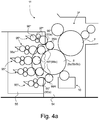
- Figures 4a and 4b schematically illustrate an intaglio printing press comprising an inking system in accordance with a second embodiment of the invention, which intaglio printing press is generally designated by reference numeral 1 II .
- Only the relevant components of the inking system are illustrated in Figures 4a and 4b , including multiple inking devices 95* that are distributed about a portion of the circumference of the plate cylinder 8 of the printing unit 3 II of the press.
- the configuration of the printing unit 3 II shown in Figures 4a and 4b is different from that shown in Figures 3a to 3c in that no ink collecting cylinder is provided and in the configuration of the inking system used to ink the plate cylinder 8.
- the inking system consists of elements designated by reference numerals 95* to 99*, and includes a plurality of (namely five) inking devices 95* that are distributed about a portion of the circumference of the plate cylinder 8.
- Each inking device 95* comprises a chablon cylinder 99* cooperating with the plate cylinder 8 and carrying a chablon plate 99a, which chablon plate 99a receives ink supplied by an associated inking unit 96*/96a*/97*.
- Each chablon plate 99a is a relief plate comprising relief portions 99A corresponding to engraved areas of the one or more intaglio printing plates 8a-8c carried by the plate cylinder 8, which engraved areas are to be inked with the ink supplied by the associated inking unit 96*/96a*/97*.
- at least one of the inking devices 95* (preferably each inking device 95* as illustrated in Figures 4a and 4b ) further comprises a selective inking cylinder 98* that is interposed between the chablon cylinder 99* and the associated inking unit 96*/96a*/97*.
- this selective inking cylinder 98* carries a selective inking plate 90a, which selective inking plate 90a receives ink supplied by the associated inking unit 96*/96a*/97*.
- This inking unit is basically similar to the inking unit 96/96a/97 shown in Figures 3a to 3c and is designed as a short inking unit comprising an ink duct 96*, 96a* with a duct roller 96* supplying ink to the associated selective inking cylinder 98* via a pair of ink application rollers 97*.
- the ink duct is likewise designed as an ink fountain with an ink fountain blade 96a* cooperating with the duct roller 96* so as to form an ink reservoir between the ink fountain blade 96a* and a portion of the circumference of the duct roller 96*.
- the selective cylinders 98* and chablon cylinders 99* are each one-segment cylinders whose diameter is one third of that of the plate cylinder 8.
- the inking units 96*/96a*/97* are advantageously located and supported, together with each selective inking cylinder 98*, in an inking carriage 55 that is retractable away from the plate cylinder 8 during maintenance operations (see e.g. Figure 4b ).
- the plate cylinder 8 is located and supported, together with the chablon cylinders 99*, the associated impression cylinder 7 and ink wiping system 10 in a stationary machine frame 54. It will once again be appreciated that this particular configuration ensures optimal accessibility to the selective inking cylinders 98*, the chablon cylinders 99* and the plate cylinder 8 during maintenance operations, for instance for the purpose of cleaning or exchanging plates.
- Figures 5a and 5b schematically illustrate an intaglio printing press comprising an inking system in accordance with a third embodiment of the invention, which intaglio printing press is generally designated by reference numeral 1 III .
- Only the relevant components of the inking system are illustrated in Figures 5a and 5b , including an ink collecting cylinder 9 designed to cooperate with the plate cylinder 8 of the printing unit 3 III of the press and to collect inks from multiple inking devices 95** that are distributed about a portion of the circumference of the ink collecting cylinder 9.
- the configuration of the printing unit 3 III shown in Figures 5a and 5b differs from that of the first and second embodiments.
- the inking system consists of elements designated by reference numerals 95**, 96**, 98** and 99**, and includes a plurality of (namely five) inking devices 95** that are distributed about a portion of the circumference of the ink collecting cylinder 9.
- Each inking device 95** comprises a chablon cylinder 99** cooperating with the ink collecting cylinder 9 and carrying a chablon plate 99a, which chablon plate 99a receives ink supplied by an associated inking unit 96**/96a**.
- Each chablon plate 99a is a relief plate comprising relief portions 99A corresponding to engraved areas of the one or more intaglio printing plates 8a-8c carried by the plate cylinder 8, which engraved areas are to be inked with the ink supplied by the associated inking unit 96**/96a**.
- at least one of the inking devices 95** (preferably each inking device 95** as illustrated in Figures 5a and 5b ) further comprises a selective inking cylinder 98** that is interposed between the chablon cylinder 99** and the associated inking unit 96**/96a**.
- this selective inking cylinder 98** carries a selective inking plate 90a, which selective inking plate 90a receives ink supplied by the associated inking unit 96**/96a**. While likewise designed as a short inking unit, this inking unit differs from the inking unit 96/96a/97, resp. 96*/96a*/97* shown in Figures 3a-3c and 4a-4b in that it comprises an ink duct 96**, 96a** with a duct roller 96** supplying ink directly to the associated selective inking cylinder 98**.
- the ink duct is likewise designed as an ink fountain with an ink fountain blade 96a** cooperating with the duct roller 96** so as to form an ink reservoir between the ink fountain blade 96a** and a portion of the circumference of the duct roller 96**.
- the duct roller 96** could be provided with engravings corresponding to engraved areas of the one or more intaglio printing plates 8a, 8b, 8c that are to be inked with the ink supplied by the inking unit 96**/96a**, in a manner similar to what is being contemplated in International Publication No. WO 2005/077656 A1 or European Patent Publication No. EP 0 176 702 A1 .
- the engraved duct roller 96** would provide the ability to modulate the volume of ink independently for each engraved areas of the intaglio printing plates 8a, 8b, 8c, while the selective inking cylinder 98** would provide the ability to precisely delineate the relevant engraved areas of the intaglio printing plates 8a, 8b, 8c to which ink is to be selectively transferred.
- the (engraved) duct roller 96** preferably exhibits the same diameter as that of the associated selective inking cylinder 98** and chablon cylinder 99**, i.e. an integer fraction 1/n of the diameter of the plate cylinder 8.
- cylinders 96**, 98**, 99** are all one-segment cylinders exhibiting a diameter that is one third of the diameter of the associated plate cylinder 8 and ink collecting cylinder 9.
- the inking units 96**/96a** are advantageously located and supported, together with each selective inking cylinder 98**, in an inking carriage 52*** that is retractable away from the ink collecting cylinder 9 during maintenance operations (see e.g. Figure 5b ).
- the ink collecting cylinder 9 is located and supported, together with the chablon cylinders 99**, in an intermediate carriage 51** that is retractable away from the plate cylinder 8 during maintenance operations.
- the plate cylinder 8 is located and supported, together with the associated impression cylinder 7 and ink wiping system 10 (not shown in Figures 5a and 5b ) in a stationary machine frame 50.
- this particular configuration ensures optimal accessibility to the selective inking cylinders 98**, the chablon cylinders 99**, the ink collecting cylinder 9 and the plate cylinder 8 during maintenance operations, for instance for the purpose of cleaning or exchanging plates and/or blankets.
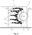
- Figure 6 schematically illustrates an intaglio printing press comprising an inking system in accordance with a fourth embodiment of the invention, which intaglio printing press is generally designated by reference numeral 1 IV .
- Only the relevant components of the inking system are illustrated in Figure 6 , including an ink collecting cylinder 9 designed to cooperate with the plate cylinder 8 of the printing unit 3 IV of the press and to collect inks from multiple inking devices 905 that are distributed about a portion of the circumference of the ink collecting cylinder 9.
- the configuration of the printing unit 3 IV shown in Figure 6 is basically similar to that of the first embodiment shown in Figures 3a to 3c , with the exception of the inking units used to supply ink to the selective inking cylinders 98.
- the inking system consists of elements designated by reference numerals 9, 98, 905, 906, 906a, 910 and 915, and includes the ink collecting cylinder 9 collecting ink patterns from a plurality of (namely five) inking devices 905 that are distributed about a portion of the circumference of the ink collecting cylinder 9.
- at least one of the inking devices 905 (preferably each inking device 905 as illustrated in Figure 6 ) comprises a selective inking cylinder 98 that cooperates with the ink collecting cylinder 9 and carries a selective inking plate 90a which receives ink supplied by an associated inking unit 906/906a/910/915.
- This inking unit differs from the inking unit used in the embodiment of Figures 3a-3c in that it is designed as a long inking unit comprising an ink duct 906, 906a with a duct roller 906 (that is advantageously designed as an ink fountain with an ink fountain blade 906a cooperating with the duct roller 906) inking the selective inking plate 90a via a plurality of ink transfer rollers 915.
- each inking unit 906/906a/910/915 further comprises a vibrator roller 910 interposed between the duct roller 906 and a first one 915a of the ink transfer rollers 915.
- Such vibrator-type inking units 906/906a/910/915 are known as such in the art, but are normally used as inking units in offset or letterpress printing presses.
- This particular inking unit 906/906a/910/915 is advantageous in that it opens the possibility to use a profiled vibrator roller 910 in accordance with the teaching of International Publication No. WO 2016/042482 A2 in the name of the instant Applicant, which publication is incorporated herein by reference in its entirety.
- the inking units 906/906a/910/915 are advantageously located and supported in an inking carriage 52*** that is retractable away from the ink collecting cylinder 9 during maintenance operations.
- the ink collecting cylinder 9 is likewise located and supported, together with each selective inking cylinder 98, in an intermediate carriage 51* that is retractable away from the plate cylinder 8 during maintenance operations.
- the plate cylinder 8 is similarly located and supported, together with the associated impression cylinder 7 and ink wiping system 10 (not shown in Figure 6 ) in a stationary machine frame 50. This ensures optimal accessibility to the selective inking cylinders 98, the ink collecting cylinder 9 and the plate cylinder 8 during maintenance operations, for instance for the purpose of cleaning or exchanging plates and/or blankets.
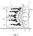
- FIG. 7 schematically illustrates an intaglio printing press comprising an inking system in accordance with a fifth embodiment of the invention, which intaglio printing press is generally designated by reference numeral 1 V . Only the relevant components of the inking system are illustrated in Figure 7 , including an ink collecting cylinder 9 designed to cooperate with the plate cylinder 8 of the printing unit 3 V of the press and to collect inks from multiple inking devices 905* that are distributed about a portion of the circumference of the ink collecting cylinder 9.
- the configuration of the printing unit 3 V shown in Figure 7 is basically similar to that of the third embodiment shown in Figures 5a and 5b , with the exception of the inking units used to supply ink to the selective inking cylinders 98**, which inking units are similar to those used in the context of the fourth embodiment of Figure 6 .
- the inking system consists of elements designated by reference numerals 9, 98**, 905*, 906*, 906a*, 910* and 915*, and includes the ink collecting cylinder 9 collecting ink patterns from a plurality of (namely five) inking devices 905* that are distributed about a portion of the circumference of the ink collecting cylinder 9.
- each inking device 905* comprises a chablon cylinder 99** cooperating with the ink collecting cylinder 9 and carrying a chablon plate 99a, which chablon plate 99a receives ink supplied by an associated inking unit 906*/906a*/910*/915* which is similar to the inking unit 906/906a/910/915 used in the context of the fourth embodiment of Figure 6 .
- at least one of the inking devices 905* (preferably each inking device 905* as illustrated in Figure 7 ) further comprises a selective inking cylinder 98** that is interposed between the chablon cylinder 99** and the associated inking unit 906*/906a*/910*/915*.
- This inking unit differs from the inking unit used in the embodiment of Figures 5a and 5b in that it is designed as a long inking unit comprising an ink duct 906*, 906a* with a duct roller 906* (that is advantageously designed as an ink fountain with an ink fountain blade 906a* cooperating with the duct roller 906*) inking the selective inking plate 90a via a plurality of ink transfer rollers 915*.
- each inking unit 906*/906a*/910*/915* further comprises a vibrator roller 910* interposed between the duct roller 906* and a first one 915a* of the ink transfer rollers 915*, thereby providing the same advantages as the fourth embodiment of Figure 6 .
- the inking units 906*/906a*/910*/915* are advantageously located and supported, together with each selective inking cylinder 98**, in an inking carriage 52**** that is retractable away from the ink collecting cylinder 9 during maintenance operations.
- the ink collecting cylinder 9 is likewise located and supported, together with the chablon cylinders 99**, in an intermediate carriage 51** that is retractable away from the plate cylinder 8 during maintenance operations.
- the plate cylinder 8 is similarly located and supported, together with the associated impression cylinder 7 and ink wiping system 10 (not shown in Figure 7 ) in a stationary machine frame 50.
- the fourth and fifth embodiments likewise rely on the use of a selective inking plate 90a similar to the selective inking plate used in the context of the first to third embodiments.
- any one of the inking devices 95, resp. 905, could be designed as a conventional inking device comprising a chablon cylinder instead of the selective inking cylinder 98.
- this process includes inking the one or more intaglio printing mediums by means of a plurality of inking devices, wherein a selective transfer of ink to the one or more intaglio printing mediums is performed by means of a selective inking cylinder provided in at least one of the inking devices, preferably in each of the inking devices, which selective inking cylinder carries a selective inking plate receiving ink supplied by an associated inking unit.
- the selective inking plate comprises a coating that is selectively structured to exhibit ink-repellent portions and perform selective transfer of ink at locations corresponding to engraved areas of the one or more intaglio printing mediums that are to be inked with the ink supplied by the associated inking unit.
- the selective transfer of ink is performed indirectly from the selective inking cylinder to the one or more intaglio printing mediums (i) via an ink collecting cylinder (as shown for instance in Figures 3a-3c and 6 ), (ii) via a chablon cylinder carrying a chablon plate comprising relief portions corresponding to engraved areas of the one or more intaglio printing mediums that are to be inked with the ink supplied by the associated inking unit (as shown in Figures 4a-4b ) or (iii) via a combination of both (as shown for instance in Figures 5a-5b and 7 ).
Landscapes
- Engineering & Computer Science (AREA)
- Mechanical Engineering (AREA)
- Rotary Presses (AREA)
- Manufacture Or Reproduction Of Printing Formes (AREA)
- Inking, Control Or Cleaning Of Printing Machines (AREA)
- Printing Plates And Materials Therefor (AREA)
- Printing Methods (AREA)
Priority Applications (6)
| Application Number | Priority Date | Filing Date | Title |
|---|---|---|---|
| EP17169509.1A EP3398782A1 (fr) | 2017-05-04 | 2017-05-04 | Système d'encrage pour encrer un cylindre d'impression en creux d'une presse d'impression en creux, presse d'impression en creux le comprenant et procédé d'encrage d'un tel cylindre d'impression en creux |
| US16/498,911 US10696042B2 (en) | 2017-05-04 | 2018-03-12 | Inking system for inking an intaglio printing cylinder of an intaglio printing press, intaglio printing press comprising the same, and process of inking such an intaglio printing cylinder |
| PCT/EP2018/056052 WO2018202344A1 (fr) | 2017-05-04 | 2018-03-12 | Système d'encrage pour l'encrage d'un cylindre gravé d'une presse d'impression en taille-douce, presse d'impression en taille-douce comprenant celui-ci, et procédé d'encrage d'un tel cylindre gravé |
| EP18708713.5A EP3619045B1 (fr) | 2017-05-04 | 2018-03-12 | Système d'encrage pour encrer un cylindre d'impression en creux d'une presse d'impression en creux, presse d'impression en creux le comprenant et procédé d'encrage d'un tel cylindre d'impression en creux |
| JP2019553964A JP6731124B2 (ja) | 2017-05-04 | 2018-03-12 | 凹版印刷機の凹版印刷胴にインク付けするためのインクシステム、これを具える凹版印刷機、およびこのような凹版印刷胴にインク付けするプロセス |
| CN201880023449.6A CN110475668B (zh) | 2017-05-04 | 2018-03-12 | 用于给凹版印刷机的凹版印刷滚筒上墨的上墨系统、包括该上墨系统的凹版印刷机以及给该凹版印刷滚筒上墨的工艺 |
Applications Claiming Priority (1)
| Application Number | Priority Date | Filing Date | Title |
|---|---|---|---|
| EP17169509.1A EP3398782A1 (fr) | 2017-05-04 | 2017-05-04 | Système d'encrage pour encrer un cylindre d'impression en creux d'une presse d'impression en creux, presse d'impression en creux le comprenant et procédé d'encrage d'un tel cylindre d'impression en creux |
Publications (1)
| Publication Number | Publication Date |
|---|---|
| EP3398782A1 true EP3398782A1 (fr) | 2018-11-07 |
Family
ID=58669737
Family Applications (2)
| Application Number | Title | Priority Date | Filing Date |
|---|---|---|---|
| EP17169509.1A Withdrawn EP3398782A1 (fr) | 2017-05-04 | 2017-05-04 | Système d'encrage pour encrer un cylindre d'impression en creux d'une presse d'impression en creux, presse d'impression en creux le comprenant et procédé d'encrage d'un tel cylindre d'impression en creux |
| EP18708713.5A Active EP3619045B1 (fr) | 2017-05-04 | 2018-03-12 | Système d'encrage pour encrer un cylindre d'impression en creux d'une presse d'impression en creux, presse d'impression en creux le comprenant et procédé d'encrage d'un tel cylindre d'impression en creux |
Family Applications After (1)
| Application Number | Title | Priority Date | Filing Date |
|---|---|---|---|
| EP18708713.5A Active EP3619045B1 (fr) | 2017-05-04 | 2018-03-12 | Système d'encrage pour encrer un cylindre d'impression en creux d'une presse d'impression en creux, presse d'impression en creux le comprenant et procédé d'encrage d'un tel cylindre d'impression en creux |
Country Status (5)
| Country | Link |
|---|---|
| US (1) | US10696042B2 (fr) |
| EP (2) | EP3398782A1 (fr) |
| JP (1) | JP6731124B2 (fr) |
| CN (1) | CN110475668B (fr) |
| WO (1) | WO2018202344A1 (fr) |
Families Citing this family (3)
| Publication number | Priority date | Publication date | Assignee | Title |
|---|---|---|---|---|
| DE102020100442A1 (de) * | 2020-01-10 | 2021-07-15 | Koenig & Bauer Ag | Tiefdruckmaschine und Verfahren zum Aufbringen von zumindest einem Druckfluid auf zumindest ein Substrat |
| DE102020102622A1 (de) * | 2020-02-03 | 2021-08-05 | Koenig & Bauer Ag | Tiefdruckwerk |
| CN115107345B (zh) * | 2021-03-23 | 2023-10-20 | 南京造币有限公司 | 一种模块化组合式双面防伪底纹印刷机 |
Citations (24)
| Publication number | Priority date | Publication date | Assignee | Title |
|---|---|---|---|---|
| GB987102A (en) | 1961-07-11 | 1965-03-24 | Gualtiero Giori | Improvements in multicolour intaglio printing by means of a single engraved printingplate |
| US4516496A (en) * | 1982-04-07 | 1985-05-14 | De La Rue Giori S.A. | Copperplate engraving machine for printing paper currency |
| EP0176702A1 (fr) | 1984-09-03 | 1986-04-09 | Komori Corporation | Machine d'impression du type hélio |
| EP0406157A1 (fr) | 1989-06-29 | 1991-01-02 | De La Rue Giori S.A. | Machine taille-douce pour l'impression des papiers valeurs |
| EP0415881A2 (fr) | 1989-08-30 | 1991-03-06 | De La Rue Giori S.A. | Machine rotative d'impression combinée, particulièrement pour imprimer les papiers de valeur |
| EP0563007A1 (fr) | 1992-03-26 | 1993-09-29 | De La Rue Giori S.A. | Machine à imprimer en creux |
| CH685380A5 (de) | 1992-03-26 | 1995-06-30 | De La Rue Giori Sa | Rotationsdruckmaschine. |
| WO1997037329A1 (fr) | 1996-04-02 | 1997-10-09 | Koenig & Bauer-Albert Ag | Procede et dispositif pour evaluer la qualite d'un materiau traite |
| WO1997036813A1 (fr) | 1996-04-02 | 1997-10-09 | Koenig & Bauer-Albert Ag | Caisse aspirante pour guidage de feuille |
| EP0873866A1 (fr) | 1997-04-14 | 1998-10-28 | De La Rue Giori S.A. | Machine taille-douce |
| WO2003047862A1 (fr) | 2001-11-27 | 2003-06-12 | Kba-Giori S.A. | Machine d'impression à gravure en creux |
| WO2003070465A1 (fr) | 2002-02-20 | 2003-08-28 | Kba-Giori S.A. | Dispositif de transport de feuilles equipe d'un element guide-feuille |
| WO2004026580A1 (fr) | 2002-09-19 | 2004-04-01 | Kba-Giori S.A. | Machine d'impression en taille-douce |
| WO2004069538A2 (fr) | 2003-02-03 | 2004-08-19 | Kba-Giori S.A. | Machine d'impression en creux |
| WO2005077656A1 (fr) | 2004-01-15 | 2005-08-25 | Kba-Giori S.A. | Systeme d'encrage pour machine d'impression en creux |
| WO2007116353A1 (fr) | 2006-04-11 | 2007-10-18 | Kba-Giori S.A. | machine d'essuyage d'encre pour une machine d'impression |
| WO2008146193A1 (fr) | 2007-05-25 | 2008-12-04 | Kba-Giori S.A. | Systèmes de presse d'impression en creux pour l'impression en creux recto-verso de feuilles pour la production de billets de banque et de titres similaires |
| WO2011077350A1 (fr) | 2009-12-22 | 2011-06-30 | Kba-Notasys Sa | Presse pour impression en taille douce avec cylindre d'impression en taille douce |
| WO2011161656A1 (fr) | 2010-06-25 | 2011-12-29 | Kba-Notasys Sa | Système de contrôle pour le contrôle en ligne d'un matériau imprimé produit sur une presse d'impression en creux |
| WO2013132471A1 (fr) | 2012-03-09 | 2013-09-12 | Kba-Notasys Sa | Système d'essuyage d'encre d'une presse d'impression en taille-douce et presse d'impression en taille-douce le comportant |
| WO2013153519A2 (fr) | 2012-04-10 | 2013-10-17 | Kba-Notasys Sa | Presse à imprimer comprenant un chariot d'encrage mobile |
| WO2013160853A2 (fr) | 2012-04-24 | 2013-10-31 | Kba-Notasys Sa | Presse à imprimer en creux |
| WO2014131479A1 (fr) * | 2013-03-01 | 2014-09-04 | Sicpa Holding Sa | Impression en creux |
| WO2016042482A2 (fr) | 2014-09-19 | 2016-03-24 | Kba-Notasys Sa | Appareil d'encrage de presse d'impression, presse d'impression comprenant celui-ci et procédé de production de rouleau vibrateur |
Family Cites Families (9)
| Publication number | Priority date | Publication date | Assignee | Title |
|---|---|---|---|---|
| DE3446619C2 (de) * | 1984-12-20 | 1991-02-14 | J.G. Mailänder GmbH & Co, 7120 Bietigheim-Bissingen | Rotations-Druckeinrichtung |
| US5415094A (en) * | 1993-10-18 | 1995-05-16 | Morrone; Ross F. | Apparatus and method for inking of an engraving die utilizing a selectively rotatable inking roller with external ribbing thereon |
| EP0726851A4 (fr) * | 1993-11-03 | 1997-04-16 | Corning Inc | Filtre colore et procede de fabrication |
| EP1445098A1 (fr) * | 2003-02-04 | 2004-08-11 | Kba-Giori S.A. | Cylindre porte-blanchet pour une machine d'impression en creux |
| WO2008146262A2 (fr) * | 2007-06-01 | 2008-12-04 | Kba-Giori S.A. | Authentification de documents de sécurité, en particulier de billets de banque |
| KR101597703B1 (ko) * | 2007-08-20 | 2016-02-26 | 알.알.도넬리앤드선즈컴퍼니 | 기판에 대한 물질의 도포를 제어하는 장치 및 방법 |
| US20110197777A1 (en) * | 2010-02-16 | 2011-08-18 | Douglas Lowell Osterberg | Variable print lithographic printing press |
| EP2746049A1 (fr) * | 2012-12-20 | 2014-06-25 | KBA-NotaSys SA | Procédé de contrôle d'une impression taille-douce et gamme de contrôle à cette fin |
| JP6150338B2 (ja) * | 2013-09-13 | 2017-06-21 | 株式会社小森コーポレーション | 番号印刷機のインキ装置 |
-
2017
- 2017-05-04 EP EP17169509.1A patent/EP3398782A1/fr not_active Withdrawn
-
2018
- 2018-03-12 US US16/498,911 patent/US10696042B2/en active Active
- 2018-03-12 WO PCT/EP2018/056052 patent/WO2018202344A1/fr not_active Ceased
- 2018-03-12 EP EP18708713.5A patent/EP3619045B1/fr active Active
- 2018-03-12 JP JP2019553964A patent/JP6731124B2/ja active Active
- 2018-03-12 CN CN201880023449.6A patent/CN110475668B/zh active Active
Patent Citations (26)
| Publication number | Priority date | Publication date | Assignee | Title |
|---|---|---|---|---|
| GB987102A (en) | 1961-07-11 | 1965-03-24 | Gualtiero Giori | Improvements in multicolour intaglio printing by means of a single engraved printingplate |
| US4516496A (en) * | 1982-04-07 | 1985-05-14 | De La Rue Giori S.A. | Copperplate engraving machine for printing paper currency |
| EP0176702A1 (fr) | 1984-09-03 | 1986-04-09 | Komori Corporation | Machine d'impression du type hélio |
| EP0406157A1 (fr) | 1989-06-29 | 1991-01-02 | De La Rue Giori S.A. | Machine taille-douce pour l'impression des papiers valeurs |
| EP0415881A2 (fr) | 1989-08-30 | 1991-03-06 | De La Rue Giori S.A. | Machine rotative d'impression combinée, particulièrement pour imprimer les papiers de valeur |
| EP0563007A1 (fr) | 1992-03-26 | 1993-09-29 | De La Rue Giori S.A. | Machine à imprimer en creux |
| CH685380A5 (de) | 1992-03-26 | 1995-06-30 | De La Rue Giori Sa | Rotationsdruckmaschine. |
| WO1997037329A1 (fr) | 1996-04-02 | 1997-10-09 | Koenig & Bauer-Albert Ag | Procede et dispositif pour evaluer la qualite d'un materiau traite |
| WO1997036813A1 (fr) | 1996-04-02 | 1997-10-09 | Koenig & Bauer-Albert Ag | Caisse aspirante pour guidage de feuille |
| EP0873866A1 (fr) | 1997-04-14 | 1998-10-28 | De La Rue Giori S.A. | Machine taille-douce |
| WO2003047862A1 (fr) | 2001-11-27 | 2003-06-12 | Kba-Giori S.A. | Machine d'impression à gravure en creux |
| WO2003070465A1 (fr) | 2002-02-20 | 2003-08-28 | Kba-Giori S.A. | Dispositif de transport de feuilles equipe d'un element guide-feuille |
| WO2004026580A1 (fr) | 2002-09-19 | 2004-04-01 | Kba-Giori S.A. | Machine d'impression en taille-douce |
| WO2004069538A2 (fr) | 2003-02-03 | 2004-08-19 | Kba-Giori S.A. | Machine d'impression en creux |
| WO2005077656A1 (fr) | 2004-01-15 | 2005-08-25 | Kba-Giori S.A. | Systeme d'encrage pour machine d'impression en creux |
| WO2007116353A1 (fr) | 2006-04-11 | 2007-10-18 | Kba-Giori S.A. | machine d'essuyage d'encre pour une machine d'impression |
| WO2008146193A1 (fr) | 2007-05-25 | 2008-12-04 | Kba-Giori S.A. | Systèmes de presse d'impression en creux pour l'impression en creux recto-verso de feuilles pour la production de billets de banque et de titres similaires |
| WO2011077350A1 (fr) | 2009-12-22 | 2011-06-30 | Kba-Notasys Sa | Presse pour impression en taille douce avec cylindre d'impression en taille douce |
| WO2011077348A1 (fr) | 2009-12-22 | 2011-06-30 | Kba-Notasys Sa | Presse à imprimer en creux avec chariot mobile supportant le rouleau collecteur d'encre |
| WO2011077351A1 (fr) | 2009-12-22 | 2011-06-30 | Kba-Notasys Sa | Presse à imprimer en creux avec chariot mobile support le rouleau collecteur d'encre presse à imprimer en creux avec chariot mobile supportant un rouleau de collecte d'encre |
| WO2011161656A1 (fr) | 2010-06-25 | 2011-12-29 | Kba-Notasys Sa | Système de contrôle pour le contrôle en ligne d'un matériau imprimé produit sur une presse d'impression en creux |
| WO2013132471A1 (fr) | 2012-03-09 | 2013-09-12 | Kba-Notasys Sa | Système d'essuyage d'encre d'une presse d'impression en taille-douce et presse d'impression en taille-douce le comportant |
| WO2013153519A2 (fr) | 2012-04-10 | 2013-10-17 | Kba-Notasys Sa | Presse à imprimer comprenant un chariot d'encrage mobile |
| WO2013160853A2 (fr) | 2012-04-24 | 2013-10-31 | Kba-Notasys Sa | Presse à imprimer en creux |
| WO2014131479A1 (fr) * | 2013-03-01 | 2014-09-04 | Sicpa Holding Sa | Impression en creux |
| WO2016042482A2 (fr) | 2014-09-19 | 2016-03-24 | Kba-Notasys Sa | Appareil d'encrage de presse d'impression, presse d'impression comprenant celui-ci et procédé de production de rouleau vibrateur |
Also Published As
| Publication number | Publication date |
|---|---|
| JP6731124B2 (ja) | 2020-07-29 |
| JP2020512221A (ja) | 2020-04-23 |
| US10696042B2 (en) | 2020-06-30 |
| CN110475668B (zh) | 2020-08-18 |
| CN110475668A (zh) | 2019-11-19 |
| US20200114642A1 (en) | 2020-04-16 |
| EP3619045A1 (fr) | 2020-03-11 |
| EP3619045B1 (fr) | 2020-12-30 |
| WO2018202344A1 (fr) | 2018-11-08 |
Similar Documents
| Publication | Publication Date | Title |
|---|---|---|
| EP3186083B1 (fr) | Presse d'impression combinée | |
| EP3585614B1 (fr) | Presse à imprimer ayant un dispositif de coulée en ligne pour la réplication et la formation d'une structure micro-optique | |
| KR101054513B1 (ko) | 요판 인쇄기의 잉크부착 유닛의 구동 | |
| EP3191307B1 (fr) | Presse d'impression combinée | |
| CN106029381B (zh) | 具有打号滚筒和额外印刷单元的多色凸版印刷机 | |
| US7464642B2 (en) | Blanket cylinder for an intaglio printing machine | |
| US10220608B2 (en) | Inking apparatus of a printing press, printing press comprising the same and method of producing a vibrator roller | |
| EP3619045B1 (fr) | Système d'encrage pour encrer un cylindre d'impression en creux d'une presse d'impression en creux, presse d'impression en creux le comprenant et procédé d'encrage d'un tel cylindre d'impression en creux | |
| JP2005512840A (ja) | 凹版印刷機 | |
| US6272987B1 (en) | Intaglio printing press | |
| JP2006516492A5 (fr) | ||
| US9333739B2 (en) | Printing press with mobile inking carriage | |
| JPH10278220A (ja) | 枚葉輪転印刷機 |
Legal Events
| Date | Code | Title | Description |
|---|---|---|---|
| PUAI | Public reference made under article 153(3) epc to a published international application that has entered the european phase |
Free format text: ORIGINAL CODE: 0009012 |
|
| AK | Designated contracting states |
Kind code of ref document: A1 Designated state(s): AL AT BE BG CH CY CZ DE DK EE ES FI FR GB GR HR HU IE IS IT LI LT LU LV MC MK MT NL NO PL PT RO RS SE SI SK SM TR |
|
| AX | Request for extension of the european patent |
Extension state: BA ME |
|
| STAA | Information on the status of an ep patent application or granted ep patent |
Free format text: STATUS: THE APPLICATION IS DEEMED TO BE WITHDRAWN |
|
| 18D | Application deemed to be withdrawn |
Effective date: 20190508 |