EP3399103B1 - Zungeneinrichtung und verfahren zur herstellung einer zungeneinrichtung - Google Patents
Zungeneinrichtung und verfahren zur herstellung einer zungeneinrichtung Download PDFInfo
- Publication number
- EP3399103B1 EP3399103B1 EP18170699.5A EP18170699A EP3399103B1 EP 3399103 B1 EP3399103 B1 EP 3399103B1 EP 18170699 A EP18170699 A EP 18170699A EP 3399103 B1 EP3399103 B1 EP 3399103B1
- Authority
- EP
- European Patent Office
- Prior art keywords
- tongue
- base block
- rail
- stock rail
- stock
- Prior art date
- Legal status (The legal status is an assumption and is not a legal conclusion. Google has not performed a legal analysis and makes no representation as to the accuracy of the status listed.)
- Active
Links
Images





Classifications
-
- E—FIXED CONSTRUCTIONS
- E01—CONSTRUCTION OF ROADS, RAILWAYS, OR BRIDGES
- E01B—PERMANENT WAY; PERMANENT-WAY TOOLS; MACHINES FOR MAKING RAILWAYS OF ALL KINDS
- E01B7/00—Switches; Crossings
- E01B7/02—Tongues; Associated constructions
-
- E—FIXED CONSTRUCTIONS
- E01—CONSTRUCTION OF ROADS, RAILWAYS, OR BRIDGES
- E01B—PERMANENT WAY; PERMANENT-WAY TOOLS; MACHINES FOR MAKING RAILWAYS OF ALL KINDS
- E01B7/00—Switches; Crossings
- E01B7/24—Heating of switches
Definitions
- the present invention relates to a tongue device according to the preamble of claim 1 and a method of manufacturing a tongue device according to the preamble of claim 14.
- Such tongue devices are used in particular, but not exclusively, in grooved rail switches. They have a stock rail, an auxiliary rail and a tongue, with a tongue bed for the tongue, on which the tongue can also slide without separate lubricants.
- Switch devices which are welded together from individual profiles, the stock rail and the steel profile used as auxiliary rail being connected by means of a high-strength steel plate, the switch being movable transversely on this steel plate as a sliding plate.
- the stock rail and the auxiliary rail are welded onto a base plate.
- the heater is located in the cavity between the skid plate and the base plate. Individual areas can be hardened by build-up welding at the wear points, but this is very time-consuming. Overall, this construction is therefore very complex.
- the DE 10 2010 037 110 A1 a raised structure. Due to this structure, however, the construction is very complex.
- the DE 101 24 624 C2 shows, on the other hand, a so-called bi-block construction, in which a lower part is made of structural steel as a unitary block.
- this structure is associated with high replacement costs in the event of maintenance.
- the DE 1 048 938 A shows a switch assembly having a stock rail, an auxiliary rail and a switch, there being a switch bed for the switch, there being a base block integrally uniting the switch bed and a base plate, the stock rail not being integrally connected to the base block, the separate stock rail is at least partially positively and/or materially connected to the base block, corresponding to the preamble of claim 1.
- the inventor has recognized that the task can be solved surprisingly easily and inexpensively by constructing the lower part of the tongue device together with the tongue bed as an integral part in the form of a base block, in particular made of high-strength steel. Then usual blanks can be used for this basic block.
- a high-strength design is advantageously understood as meaning the use of high-strength steel with a Brinell hardness in the range from 300 to 460 HB.
- conventional construction or rail steels can also be used for the base block, in which case the tongue should then be designed with a correspondingly reduced hardness.
- This reduction in hardness is preferably at least 10%, in particular at least 20%.
- such a reduction in hardness is also useful in the case of a high-strength design of the base block.
- Rail steel usually has a Brinell hardness in the range of 200 to 260 HB, but a special post-treatment can also be used to achieve greater hardnesses from 290 HB, in which case one no longer speaks of naturally hard steel qualities.
- Structural steel on the other hand, can be supplied with a Brinell hardness of less than 200 HB. Structural steels can easily be used for the auxiliary rail because the auxiliary rail is not driven on.
- the base block could have a hardness of 400 HB, the tongue a hardness of 320-360 HB (but also less) and the stock rail also a hardness of 400 HB exhibit. This then involves a high-strength design of the base block and, overall, of the entire switch mechanism.
- base block 260 HB If the base block is not high-strength, but instead the wearing components are made of (structural or) rail steel, an embodiment could look as follows: base block 260 HB, tongue 210-240 HB, stock rail 260 HB. This configuration is also useful if the hardness of the rail before and after a switch is not greater and the wear resistance requirements are not as high.
- the following hardness ratios should preferably exist: base block with a hardness of at least 10-20% more than tongue, the hardness of the stock rail is less than or equal to the hardness of the base block, the possibly non-replaceable stock rail is harder than the tongue because the tongue is the only one Component can be made easily interchangeable, and the auxiliary rail has a hardness that is less than or equal to the hardness of the base block, less than or equal to the hardness of the tongue and / or less than or equal to the hardness of the stock rail.
- the switch device in particular for grooved rail switches, thus has a stock rail, an auxiliary rail and a switch, with a switch bed for the switch, and is characterized in that there is a base block which integrally combines the switch bed and a base plate, with the Base block is preferably formed from a high-strength steel grade.
- This base block is therefore designed in one piece, i.e. it can have cutouts and the like, but it does not include any welded or otherwise attached parts, for example. These further parts are not part of the basic block.
- the stock rail is not integrally connected to the base block.
- the side rails are not integrally connected to the base block.
- the switch device can then be produced in a particularly simple manner, and conventional steel billets can be used for the stock rail or the auxiliary rail, for example.
- the stock rail and/or the auxiliary rail are formed from a material that differs from the base block, whereby they are preferably formed from structural steel or rail steel and the base block is formed in particular from high-strength steel, which is preferably produced by casting is made.
- high-strength steel is also used, at least for the parts that are heavily stressed during operation, such as the stock rail. It can be provided that the stock rail is an integral part of the base block.
- the stock rail as a separate part, is at least partially connected to the base block with a form fit and/or material connection, with the material connection preferably being in the form of a weld. Then this connection is particularly secure and at the same time easy to assemble.
- the stock rail rests on the base block. This results in a particularly secure connection, because the stock rail does not have to be supported against a base of the switch device that cannot be specified in more detail, as a result of which considerable leverage forces would possibly act on the base block.
- the separate stock rail has a projection which engages in an undercut of the base block in such a way that the stock rail is prevented from tilting away from the auxiliary rail. Then there is a special ability to absorb horizontal forces, such as can always arise during operation when rail vehicles drive over them.
- the projection runs horizontally and in particular has a length that is less than or equal to a length of a threading aid on the base block.
- the base block has a recess on the rear side of the stock rail in relation to the tongue, in which a securing means for fastening the stock rail is arranged.
- This securing means can be welded or screwed to the base block.
- An advantageous development provides that there is a heater which is arranged between stock rail and base block or between auxiliary rail and base block, with the heater preferably being arranged in a recess in the base block, the auxiliary rail and/or the stock rail.
- the heating is then advantageously encapsulated and largely shielded from environmental influences, with the heating nevertheless remaining relatively easily accessible for maintenance.
- this recess and/or a separate casing, preferably a casing tube for the heater has a drainage connection.
- the heater has a longer service life.
- drainage which is designed as an opening, preferably as a bore, and/or which is arranged in the area in front of the tongue tip in the base block.
- the tongue bed is designed to be inclined in the direction of the opening relative to the horizontal if the given longitudinal inclination of the track system is too small for natural drainage.
- This inclination is preferably at least 0.5° and in particular at least 1° .
- the opening is located less than 3 cm, in particular less than 1 cm, from the tip of the tongue, the drainage is particularly effective and the tongue device is nevertheless compact.
- the heating consists of a heating rod in a cladding tube, with the cladding tube not crossing the drainage but ending at most in the drainage.
- the drainage does not interfere with the heating device and, moreover, the cladding tube can be drained into the drainage.
- the connecting means between the tongue and an adjusting device preferably in the area where the connecting means passes through the side rail, there is a barrier between the tongue bed and the adjusting box against water overflow, with the barrier in particular being raised relative to the tongue bed Edge is formed. This is preferably a raised edge of the auxiliary rail. Then a transfer of moisture from the tongue area into the control box is made more difficult or completely avoided.
- a tongue support Layer preferably at least one material from the group: ceramic material, metallic material, metallic alloys, mixture of ceramic materials and mixtures thereof.
- This layer which can be designed as a coating or as a prefabricated plate, for example, can cover the entire tongue support or only be present in sections.
- the tongue device can be adapted very flexibly to specific needs.
- the tongue has an actuating rod which extends through the auxiliary rail in order to be able to be connected preferably outside of the auxiliary rail with a coupling to the slide rod of an actuating device.
- the switch device can be made very narrow, since the coupling between the switch and the slide rod is not installed in the switch device itself, but in a control box arranged behind the auxiliary rail. This further promotes the dewatering of the tongue bed, since no indentations and the like are required in the base block for accommodating this coupling.
- the durability of the tongue device is improved since the tongue does not have to slide over corresponding edges of such a recess.
- Protection is also claimed for the method according to the invention, defined in claim 14, for producing a switch device, in particular for grooved rail points, with a stock rail, an auxiliary rail and a switch, a switch bed being provided for the switch, which is characterized in that a base block, integrally uniting the tongue bed and a base plate is used, wherein the stock rail (14a; 14b; 616; 702; 802) is not integrally connected to the base block (12a, 12b, 12c, 12d, 12e; 620; 704; 804).
- the stock rail (14a; 14b; 616; 702; 802) as a separate part is connected to the base block (12a, 12b, 12c; 620; 704; 804) at least in regions in a form-fitting and/or material-locking manner whereby the stock rail (14a; 14b; 616; 702; 802) has a projection (36a; 36b; 638) which fits into an undercut (38a; 38b; 640) of the base block (12a, 12b, 12c; 620; 704 ; 804) so as to prevent the stock rail (14a; 14b; 616; 702; 802) from tipping away from the side rail (16a, 16c, 16d; 612) with the projection (36a; 36b; 638) running horizontally .
- the tongue device according to the invention is manufactured in accordance with one of claims 2 to 13 .
- a base block on which a thin, high-strength sliding plate that is not itself mechanically load-bearing is applied to form a tongue bed.
- the base block is preferably formed from a non-high-strength steel, for example structural steel or rail steel.
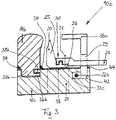
- the switch device 10a, 10b, 10c has a base block 12a, 12b, 12c on which a stock rail 14a, 14b is arranged and an auxiliary rail 16a, 16c.
- the base block 12a, 12b, 12c integrally comprises the lower part 17a, 17b, 17c of the tongue device 10a, 10b, 10c and the tongue bed 18, which serves as a support for the tongue 20.
- a heater 22a, 22b, 22c is provided for heating the tongue device 10a, 10b, 10c.
- This opening 24 is designed as a bore that is located max. 3 cm in front of the tip 25 of the tongue 20 and extends essentially over the entire width of the tongue bed extends.
- the tongue 20 has a tongue foot 26 on which an adjusting rod 28 is arranged.
- This control rod 28 is guided through an opening 29 in the side rail 16a, 16b and is connected in a control box, not shown in detail, in the usual way by means of a coupling to the slide rod of a control device (not shown).
- connection 30 , 31 between the tongue base 26 and the adjusting rod 28 is connected to a toothing 30 in the horizontal direction and secured by means of a screw connection 31 .
- this connection 30, 31 can absorb very high, horizontally acting forces without wearing out.
- switch device 10a, 10b, 10c no space has to be provided within the switch device 10a, 10b, 10c, i.e. in the base block 12a, 12b, 12c, for the coupling 50 between the switch 20 and the slide rod 48, so that the switch device 10a, 10b, 10c can be made narrower overall.
- the heater 22a is arranged in a recess 32a of the base block 12a, specifically between the stock rail 14a and the base block 12a. This effectively seals off and protects the heater 22a from the environment.
- the stock rail 14a is welded to the base block 12a on both sides 34, as a result of which there is a material bond.
- the stock rail 14a has a projection 36a on a shoulder 37a, which engages in a corresponding undercut 38a in the base block 12a, this undercut 38a being arranged in the recess 32a.
- the projection 36a with the projection 37a is inserted from above into the recess 32a and pushed in the direction of the side rail 16a until the projection 36a is fully inserted into the undercut 38a, after which the welds 34 are made.
- the heater 22a is subsequently inserted into the remaining part of the recess 32a from the end face.
- connection between the base block 12a and the stock rail 14a can also absorb very high horizontal forces.
- the special feature is that the heater 22b is arranged in a recess 32b of the base block 12b, specifically between the side rail 16b and the base block 12b. As a result, here too the heater 22b is effectively closed off and protected from the environment.
- the stock rail 14b is in turn welded to the base block 12b on both sides 34, as a result of which there is a material connection.
- the stock rail 14b has a projection 36b on a shoulder 37b, which engages in a corresponding undercut 38b in the base block 12b, this undercut 38b also being as in FIG 1 is located in the recess 32b.
- the shoulder 37b with the projection 36b essentially completely fills the recess 32 with the undercut 38b.
- the side rail 16a is also attached laterally to the base block 12b by means of screw connections 40b.
- This attachment 40b is particularly maintenance-friendly with regard to the heater 22b, since the heater 22b is quickly accessible as a result.
- the special feature is that the heater 22c is arranged in a recess 32c of the base block 12c, specifically between the side rail 16c and the base block 12c. As a result, the heater 22c is also effectively closed off and protected from the environment here.
- the auxiliary rail 16c is not arranged laterally, but is inserted and welded 44 into an antechamber 42 of the recess 32c in the base block 12c.
- the 4 and 5 finally serve for the purely schematic comparison of the switch device 10d according to the invention with a conventional switch device 100, which is embodied in a monoblock design, for example.
- the switch device 10d has a base block 12d on which a stock rail 14d and an auxiliary rail 16d are arranged.
- the base block 12d in turn integrally combines the lower part 17d of the tongue device 10d and the tongue bed 18d for the tongue 20d.
- the tongue foot 26d is toothed 30d connected to an adjusting rod 28d and secured with a screw connection 31, which extends through an opening 29d in the side rail 16d into an adjusting box 46.
- a control device 47 (not shown) with a slide rod 48 which is connected via a coupling 50 to the control rod 28d.
- the screw connection 31 can be released in the control box 46 when the tongue 20d is as far as possible.
- the control box 46 has a control box cover 46' which is not connected to the end wall 46'' of the control box 46.
- the adjusting rod 28d and the special type of connection between the adjusting rod 28d and the tongue foot 26d do not require any recesses to be provided in the base block 12d.
- this connection is only slightly high, so that it can be inserted into the opening 29d in the side rail 16d, so that the tongue device 10d is designed to be very narrow overall.
- the monobloc switch device 100 shown are stock rail 102, the lower part 104 of the switch device 100 with the switch bed 106 and the side rail 108 integrally, ie made in one piece from a block 109.
- the tongue 110 is connected here with its tongue foot 112 directly to the slide rod 48 via the coupling 50 . Since this conventional coupling 50 is relatively deep, a corresponding recess 114 must be provided in the lower part 104 and the tongue bed 106 of the tongue device, and the opening 116 in the side rail 108 must be higher than in 4 be trained. Overall, the tongue device 100 must also be wider than in 4 be executed because the coupling 50 must be releasable from above and the tongue with an integral foot must be able to be removed upwards from the tongue device 100.
- the special feature of the tongue device 10e is that in comparison to the tongue device 10d 4 the base block 12e also includes the stock rail 14e integrally.
- the second coupling 606 between the adjusting rod 602 and the tongue 604 consists in the fact that the adjusting rod 602 has a head 608 which overhangs the outer diameter of the rest of the adjusting rod 602 .
- a stepped bore 610 is made in the tongue 604, through which the actuating rod 602 and its head 608 can be threaded, so that there is a form fit in the direction of the side rail 612.
- the head 608 has a circular basic shape, with two opposite sides being flattened in parallel.
- the bore 610 is provided with a cover 614 which points towards the stock rail 616 and has a contour that fits the outer contour of the head 608 .
- the cavity 618 behind the cover 614 again has a circular outer contour so that the head 608 can be freely rotated in the cavity 618 .
- This configuration thus creates a bayonet lock 606 between the actuating rod 602 and the tongue 604, which is designed to be particularly low-maintenance and safe.
- the head 608 of the actuating rod 602 is arranged countersunk in the tongue 604, so that mutual damage between the stock rail 616 and the head 608 is ruled out.
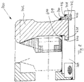
- the tongue device 600 has a base block 620 on a tongue bed 622 for the tongue 602 .
- the side rail 612 is connected directly to the base block 620 by means of two weld seams 624, the contours of the side rail 612 and base block 620 being formed in this connection area in such a way that a heating chamber 626 is formed for the heating element 630 arranged in a casing tube 628.
- a heating chamber 626 is formed for the heating element 630 arranged in a casing tube 628.
- the heating chamber 626 terminates in a drain (not shown) located in front of the tongue tip (not shown).
- a drain not shown
- both the heating chamber 626 and the jacket tube 628 can be drained directly into the drainage and the heating rod 630 does not cross through the drainage, which improves the function.
- the tongue 602 with its lower edge 632 does not have to have edges and recesses of the drainage in the tongue bed 622 move, which significantly reduces the wear of tongue 602 and tongue bed 622.
- the tongue bed 622 is arranged in one piece and uninterruptedly under the movable sections of the tongue 602, since all connecting means 602 between the tongue 602 and the actuating device (not shown) in the actuating box 636 in the area of the tongue bed 622 do not extend above the vertical level of the lower edge 632 of the tongue 602 extend downwards.
- the axis A of the actuating rod 602 is also arranged in such a way that the actuating rod 602 does not touch the side rail 612 and, in particular, its edge 634 when the tongue device 600 is in operation.
- the edge 634 of the side rail 612 is raised above the vertical level of the tongue bed 622 . As a result, no water can penetrate from the area of the tongue bed 622 into the control box 636, which is not shown in detail.
- the stock rail 616 has a horizontal projection 638 located under a horizontal undercut 640 of the base block 620 .
- a threading aid in the form of a beveled recess 642, the geometry of which is dimensioned in such a way that it can be placed without any problems.
- the length of the projection 636 is the same for this purpose, but preferably somewhat smaller than the horizontal distance of the lower edge 616a of the stock rail 616 from the edge 642a of the recess 642.
- the stock rail 616 is in turn fastened to the base block 620 with weld seams 644.
- the contour of the tongue 602 pointing towards the stock rail 616 is designed in such a way that in 7 a cavity 646 is formed between the tongue 602 and the stock rail 616 when the tongue 602 is in the abutting state shown on the stock rail 616 . Moisture and dirt located between tongue 602 and stock rail 616 can escape through this cavity 646, so that the function of tongue device 600 is not impaired.
- this tongue device 600 thus offers optimal drainage. It is easy to install and maintain and, overall, requires very little maintenance, while having a very simple design and being able to be produced inexpensively.
- a seventh preferred embodiment of the tongue device 700 according to the invention is shown, this solution being different from the tongue device 600 7 by the connection of the stock rail 702 to the base block 704.
- a securing element 706 here, which is inserted into a gap 708 between the base block 704 and the stock rail 702 .
- This securing member 706 may have any shape as long as it can be fixed in the gap. Here it has steps 710, 712 for attachment to stock rail 702 and base block 704 by welds 714, 716.
- connection 806 between the stock rail 802 and the base block 804 opposite the positive connection made up of horizontal undercut 640 and horizontal projection 638, as a result of which the connection requires particularly little installation space and the threading of the stock rail 802 into the base block 804 can also be carried out particularly easily.
- the switch device 10a, 10b, 10c, 10d, 10e, 600, 700, 800 according to the invention has a high level of durability, the manufacturing effort and the manufacturing costs are very low. In addition, the maintenance costs are very low. Overall, the switch device 10a, 10b, 10c, 10d, 10e, 600, 700, 800 according to the invention can be made much more compact than the usual switch device 100 and it can be drained much better.
Landscapes
- Engineering & Computer Science (AREA)
- Mechanical Engineering (AREA)
- Architecture (AREA)
- Civil Engineering (AREA)
- Structural Engineering (AREA)
- Railway Tracks (AREA)
- Containers Opened By Tearing Frangible Portions (AREA)
Applications Claiming Priority (2)
| Application Number | Priority Date | Filing Date | Title |
|---|---|---|---|
| DE102017109635.3A DE102017109635A1 (de) | 2017-05-04 | 2017-05-04 | Zungeneinrichtung und Verfahren zur Herstellung einer Zungeneinrichtung |
| DE102017109636.1A DE102017109636A1 (de) | 2017-05-04 | 2017-05-04 | Zungeneinrichtung und Verfahren zur Herstellung einer Zungeneinrichtung |
Publications (2)
| Publication Number | Publication Date |
|---|---|
| EP3399103A1 EP3399103A1 (de) | 2018-11-07 |
| EP3399103B1 true EP3399103B1 (de) | 2022-11-02 |
Family
ID=62116711
Family Applications (1)
| Application Number | Title | Priority Date | Filing Date |
|---|---|---|---|
| EP18170699.5A Active EP3399103B1 (de) | 2017-05-04 | 2018-05-03 | Zungeneinrichtung und verfahren zur herstellung einer zungeneinrichtung |
Country Status (3)
| Country | Link |
|---|---|
| EP (1) | EP3399103B1 (pl) |
| ES (1) | ES2935343T3 (pl) |
| PL (1) | PL3399103T3 (pl) |
Families Citing this family (2)
| Publication number | Priority date | Publication date | Assignee | Title |
|---|---|---|---|---|
| LU101697B1 (fr) * | 2020-03-17 | 2021-09-17 | Vossloh Cogifer Sa | Ensemble pour appareil de voie |
| CN114908619B (zh) * | 2022-05-30 | 2024-05-28 | 中国铁建重工集团股份有限公司 | 一种护轨装置 |
Citations (1)
| Publication number | Priority date | Publication date | Assignee | Title |
|---|---|---|---|---|
| DE102010037110A1 (de) * | 2010-05-12 | 2011-11-17 | Voestalpine Bwg Gmbh & Co. Kg | Oberbauvorrichtung |
Family Cites Families (4)
| Publication number | Priority date | Publication date | Assignee | Title |
|---|---|---|---|---|
| DE521341C (de) * | 1929-10-18 | 1931-03-20 | Schmidt Paul | Weiche, insbesondere fuer Rillenschienen |
| DE1048938B (de) * | 1957-01-11 | 1959-01-22 | Gutehoffnungshuette Sterkrade | Federzungenvorrichtung, insbesondere fuer Rillenschienenweichen, in Blockkonstruktion |
| DE19825792A1 (de) * | 1998-06-10 | 1999-12-16 | Schreck Mieves Gmbh | Oberbau-Zungenvorrichtung |
| DE102012103713A1 (de) * | 2012-04-27 | 2013-10-31 | Thyssenkrupp Gft Gleistechnik Gmbh | Zungenvorrichtung für eine Weichenanlage |
-
2018
- 2018-05-03 EP EP18170699.5A patent/EP3399103B1/de active Active
- 2018-05-03 PL PL18170699.5T patent/PL3399103T3/pl unknown
- 2018-05-03 ES ES18170699T patent/ES2935343T3/es active Active
Patent Citations (1)
| Publication number | Priority date | Publication date | Assignee | Title |
|---|---|---|---|---|
| DE102010037110A1 (de) * | 2010-05-12 | 2011-11-17 | Voestalpine Bwg Gmbh & Co. Kg | Oberbauvorrichtung |
Also Published As
| Publication number | Publication date |
|---|---|
| ES2935343T3 (es) | 2023-03-06 |
| EP3399103A1 (de) | 2018-11-07 |
| PL3399103T3 (pl) | 2023-02-06 |
Similar Documents
| Publication | Publication Date | Title |
|---|---|---|
| DE3339442C1 (de) | Herzstueck fuer Weichen oder Kreuzungen und Verfahren zur Herstellung eines solchen Herzstueckes | |
| WO1998020203A1 (de) | Unterbau für ein gleis für schienenfahrzeuge | |
| EP3258022B1 (de) | Ankerschiene und bauwerk mit einer ankerschiene | |
| WO2019025232A1 (de) | Profilschiene mit versteifungselement | |
| EP2501858B1 (de) | Bauwerklager | |
| EP3399103A1 (de) | Zungeneinrichtung und verfahren zur herstellung einer zungeneinrichtung | |
| DE19908388A1 (de) | Bauelement zur Wärmedämmung | |
| DE102008026661B4 (de) | Verkehrsleitwand | |
| DD289568A5 (de) | Herzstueck mit herzspitze aus gegossenem hartmanganstahl | |
| DE102017109636A1 (de) | Zungeneinrichtung und Verfahren zur Herstellung einer Zungeneinrichtung | |
| DE4006691C2 (de) | Stahltürzarge mit Schwellenprofil | |
| DE102017109635A1 (de) | Zungeneinrichtung und Verfahren zur Herstellung einer Zungeneinrichtung | |
| WO2007124874A1 (de) | Hubfenster | |
| DE202008000463U1 (de) | Schieberkappe für den Straßeneinbau | |
| DE3744017C2 (de) | Stahlbeton-Raumzelle, insbesondere Fertiggarage | |
| EP3399102B1 (de) | Zungeneinrichtung mit stellvorrichtung und verfahren zur herstellung einer zungeneinrichtung mit stellvorrichtung, insbesondere für rillenschienenweichen | |
| EP4317581A1 (de) | Zungenvorrichtung und verfahren zur herstellung einer zungenvorrichtung | |
| DE102005024441B4 (de) | Herzstückblock | |
| DE19920146A1 (de) | Verfahren zur Justierung sowie Lagerung einer Schiene für Schienenfahrzeuge | |
| EP3611305A1 (de) | Wandelement für eine verkehrsleit- und/oder absperrwand | |
| EP1455017A2 (de) | Herzstück | |
| DE102006000816B3 (de) | Führungsschiene für den Umlenkbeschlag eines Sicherheitsgurtes für Kraftfahrzeuge | |
| EP3101207B1 (de) | Schiebetüranordnung | |
| EP1068126A1 (de) | Sattelkupplung | |
| EP2542717B1 (de) | Hakenbolzen zur schienenbefestigung auf hohlschwellen |
Legal Events
| Date | Code | Title | Description |
|---|---|---|---|
| PUAI | Public reference made under article 153(3) epc to a published international application that has entered the european phase |
Free format text: ORIGINAL CODE: 0009012 |
|
| STAA | Information on the status of an ep patent application or granted ep patent |
Free format text: STATUS: THE APPLICATION HAS BEEN PUBLISHED |
|
| AK | Designated contracting states |
Kind code of ref document: A1 Designated state(s): AL AT BE BG CH CY CZ DE DK EE ES FI FR GB GR HR HU IE IS IT LI LT LU LV MC MK MT NL NO PL PT RO RS SE SI SK SM TR |
|
| AX | Request for extension of the european patent |
Extension state: BA ME |
|
| STAA | Information on the status of an ep patent application or granted ep patent |
Free format text: STATUS: REQUEST FOR EXAMINATION WAS MADE |
|
| 17P | Request for examination filed |
Effective date: 20190429 |
|
| RBV | Designated contracting states (corrected) |
Designated state(s): AL AT BE BG CH CY CZ DE DK EE ES FI FR GB GR HR HU IE IS IT LI LT LU LV MC MK MT NL NO PL PT RO RS SE SI SK SM TR |
|
| STAA | Information on the status of an ep patent application or granted ep patent |
Free format text: STATUS: EXAMINATION IS IN PROGRESS |
|
| 17Q | First examination report despatched |
Effective date: 20190711 |
|
| RAP1 | Party data changed (applicant data changed or rights of an application transferred) |
Owner name: SUESS, JOACHIM |
|
| GRAP | Despatch of communication of intention to grant a patent |
Free format text: ORIGINAL CODE: EPIDOSNIGR1 |
|
| STAA | Information on the status of an ep patent application or granted ep patent |
Free format text: STATUS: GRANT OF PATENT IS INTENDED |
|
| INTG | Intention to grant announced |
Effective date: 20220601 |
|
| GRAS | Grant fee paid |
Free format text: ORIGINAL CODE: EPIDOSNIGR3 |
|
| GRAA | (expected) grant |
Free format text: ORIGINAL CODE: 0009210 |
|
| STAA | Information on the status of an ep patent application or granted ep patent |
Free format text: STATUS: THE PATENT HAS BEEN GRANTED |
|
| AK | Designated contracting states |
Kind code of ref document: B1 Designated state(s): AL AT BE BG CH CY CZ DE DK EE ES FI FR GB GR HR HU IE IS IT LI LT LU LV MC MK MT NL NO PL PT RO RS SE SI SK SM TR |
|
| REG | Reference to a national code |
Ref country code: GB Ref legal event code: FG4D Free format text: NOT ENGLISH |
|
| REG | Reference to a national code |
Ref country code: CH Ref legal event code: EP Ref country code: AT Ref legal event code: REF Ref document number: 1528827 Country of ref document: AT Kind code of ref document: T Effective date: 20221115 |
|
| REG | Reference to a national code |
Ref country code: DE Ref legal event code: R096 Ref document number: 502018010944 Country of ref document: DE |
|
| REG | Reference to a national code |
Ref country code: IE Ref legal event code: FG4D Free format text: LANGUAGE OF EP DOCUMENT: GERMAN |
|
| REG | Reference to a national code |
Ref country code: NL Ref legal event code: FP |
|
| REG | Reference to a national code |
Ref country code: LT Ref legal event code: MG9D |
|
| REG | Reference to a national code |
Ref country code: ES Ref legal event code: FG2A Ref document number: 2935343 Country of ref document: ES Kind code of ref document: T3 Effective date: 20230306 |
|
| PG25 | Lapsed in a contracting state [announced via postgrant information from national office to epo] |
Ref country code: SE Free format text: LAPSE BECAUSE OF FAILURE TO SUBMIT A TRANSLATION OF THE DESCRIPTION OR TO PAY THE FEE WITHIN THE PRESCRIBED TIME-LIMIT Effective date: 20221102 Ref country code: PT Free format text: LAPSE BECAUSE OF FAILURE TO SUBMIT A TRANSLATION OF THE DESCRIPTION OR TO PAY THE FEE WITHIN THE PRESCRIBED TIME-LIMIT Effective date: 20230302 Ref country code: NO Free format text: LAPSE BECAUSE OF FAILURE TO SUBMIT A TRANSLATION OF THE DESCRIPTION OR TO PAY THE FEE WITHIN THE PRESCRIBED TIME-LIMIT Effective date: 20230202 Ref country code: LT Free format text: LAPSE BECAUSE OF FAILURE TO SUBMIT A TRANSLATION OF THE DESCRIPTION OR TO PAY THE FEE WITHIN THE PRESCRIBED TIME-LIMIT Effective date: 20221102 Ref country code: FI Free format text: LAPSE BECAUSE OF FAILURE TO SUBMIT A TRANSLATION OF THE DESCRIPTION OR TO PAY THE FEE WITHIN THE PRESCRIBED TIME-LIMIT Effective date: 20221102 |
|
| PG25 | Lapsed in a contracting state [announced via postgrant information from national office to epo] |
Ref country code: RS Free format text: LAPSE BECAUSE OF FAILURE TO SUBMIT A TRANSLATION OF THE DESCRIPTION OR TO PAY THE FEE WITHIN THE PRESCRIBED TIME-LIMIT Effective date: 20221102 Ref country code: LV Free format text: LAPSE BECAUSE OF FAILURE TO SUBMIT A TRANSLATION OF THE DESCRIPTION OR TO PAY THE FEE WITHIN THE PRESCRIBED TIME-LIMIT Effective date: 20221102 Ref country code: IS Free format text: LAPSE BECAUSE OF FAILURE TO SUBMIT A TRANSLATION OF THE DESCRIPTION OR TO PAY THE FEE WITHIN THE PRESCRIBED TIME-LIMIT Effective date: 20230302 Ref country code: HR Free format text: LAPSE BECAUSE OF FAILURE TO SUBMIT A TRANSLATION OF THE DESCRIPTION OR TO PAY THE FEE WITHIN THE PRESCRIBED TIME-LIMIT Effective date: 20221102 Ref country code: GR Free format text: LAPSE BECAUSE OF FAILURE TO SUBMIT A TRANSLATION OF THE DESCRIPTION OR TO PAY THE FEE WITHIN THE PRESCRIBED TIME-LIMIT Effective date: 20230203 |
|
| PGFP | Annual fee paid to national office [announced via postgrant information from national office to epo] |
Ref country code: LU Payment date: 20230517 Year of fee payment: 6 |
|
| P01 | Opt-out of the competence of the unified patent court (upc) registered |
Effective date: 20230527 |
|
| PG25 | Lapsed in a contracting state [announced via postgrant information from national office to epo] |
Ref country code: SM Free format text: LAPSE BECAUSE OF FAILURE TO SUBMIT A TRANSLATION OF THE DESCRIPTION OR TO PAY THE FEE WITHIN THE PRESCRIBED TIME-LIMIT Effective date: 20221102 Ref country code: RO Free format text: LAPSE BECAUSE OF FAILURE TO SUBMIT A TRANSLATION OF THE DESCRIPTION OR TO PAY THE FEE WITHIN THE PRESCRIBED TIME-LIMIT Effective date: 20221102 Ref country code: EE Free format text: LAPSE BECAUSE OF FAILURE TO SUBMIT A TRANSLATION OF THE DESCRIPTION OR TO PAY THE FEE WITHIN THE PRESCRIBED TIME-LIMIT Effective date: 20221102 Ref country code: DK Free format text: LAPSE BECAUSE OF FAILURE TO SUBMIT A TRANSLATION OF THE DESCRIPTION OR TO PAY THE FEE WITHIN THE PRESCRIBED TIME-LIMIT Effective date: 20221102 |
|
| PGFP | Annual fee paid to national office [announced via postgrant information from national office to epo] |
Ref country code: NL Payment date: 20230519 Year of fee payment: 6 Ref country code: FR Payment date: 20230517 Year of fee payment: 6 Ref country code: ES Payment date: 20230621 Year of fee payment: 6 Ref country code: DE Payment date: 20230522 Year of fee payment: 6 Ref country code: CZ Payment date: 20230421 Year of fee payment: 6 Ref country code: CH Payment date: 20230602 Year of fee payment: 6 |
|
| REG | Reference to a national code |
Ref country code: DE Ref legal event code: R097 Ref document number: 502018010944 Country of ref document: DE |
|
| PG25 | Lapsed in a contracting state [announced via postgrant information from national office to epo] |
Ref country code: SK Free format text: LAPSE BECAUSE OF FAILURE TO SUBMIT A TRANSLATION OF THE DESCRIPTION OR TO PAY THE FEE WITHIN THE PRESCRIBED TIME-LIMIT Effective date: 20221102 Ref country code: AL Free format text: LAPSE BECAUSE OF FAILURE TO SUBMIT A TRANSLATION OF THE DESCRIPTION OR TO PAY THE FEE WITHIN THE PRESCRIBED TIME-LIMIT Effective date: 20221102 |
|
| PGFP | Annual fee paid to national office [announced via postgrant information from national office to epo] |
Ref country code: TR Payment date: 20230427 Year of fee payment: 6 Ref country code: PL Payment date: 20230424 Year of fee payment: 6 Ref country code: AT Payment date: 20230516 Year of fee payment: 6 |
|
| PLBE | No opposition filed within time limit |
Free format text: ORIGINAL CODE: 0009261 |
|
| STAA | Information on the status of an ep patent application or granted ep patent |
Free format text: STATUS: NO OPPOSITION FILED WITHIN TIME LIMIT |
|
| PGFP | Annual fee paid to national office [announced via postgrant information from national office to epo] |
Ref country code: BE Payment date: 20230517 Year of fee payment: 6 |
|
| 26N | No opposition filed |
Effective date: 20230803 |
|
| PGFP | Annual fee paid to national office [announced via postgrant information from national office to epo] |
Ref country code: GB Payment date: 20230522 Year of fee payment: 6 |
|
| PG25 | Lapsed in a contracting state [announced via postgrant information from national office to epo] |
Ref country code: SI Free format text: LAPSE BECAUSE OF FAILURE TO SUBMIT A TRANSLATION OF THE DESCRIPTION OR TO PAY THE FEE WITHIN THE PRESCRIBED TIME-LIMIT Effective date: 20221102 |
|
| PG25 | Lapsed in a contracting state [announced via postgrant information from national office to epo] |
Ref country code: MC Free format text: LAPSE BECAUSE OF FAILURE TO SUBMIT A TRANSLATION OF THE DESCRIPTION OR TO PAY THE FEE WITHIN THE PRESCRIBED TIME-LIMIT Effective date: 20221102 |
|
| PG25 | Lapsed in a contracting state [announced via postgrant information from national office to epo] |
Ref country code: MC Free format text: LAPSE BECAUSE OF FAILURE TO SUBMIT A TRANSLATION OF THE DESCRIPTION OR TO PAY THE FEE WITHIN THE PRESCRIBED TIME-LIMIT Effective date: 20221102 |
|
| REG | Reference to a national code |
Ref country code: IE Ref legal event code: MM4A |
|
| PG25 | Lapsed in a contracting state [announced via postgrant information from national office to epo] |
Ref country code: IE Free format text: LAPSE BECAUSE OF NON-PAYMENT OF DUE FEES Effective date: 20230503 |
|
| PG25 | Lapsed in a contracting state [announced via postgrant information from national office to epo] |
Ref country code: IE Free format text: LAPSE BECAUSE OF NON-PAYMENT OF DUE FEES Effective date: 20230503 |
|
| PG25 | Lapsed in a contracting state [announced via postgrant information from national office to epo] |
Ref country code: IT Free format text: LAPSE BECAUSE OF FAILURE TO SUBMIT A TRANSLATION OF THE DESCRIPTION OR TO PAY THE FEE WITHIN THE PRESCRIBED TIME-LIMIT Effective date: 20221102 |
|
| PG25 | Lapsed in a contracting state [announced via postgrant information from national office to epo] |
Ref country code: BG Free format text: LAPSE BECAUSE OF FAILURE TO SUBMIT A TRANSLATION OF THE DESCRIPTION OR TO PAY THE FEE WITHIN THE PRESCRIBED TIME-LIMIT Effective date: 20221102 |
|
| PG25 | Lapsed in a contracting state [announced via postgrant information from national office to epo] |
Ref country code: BG Free format text: LAPSE BECAUSE OF FAILURE TO SUBMIT A TRANSLATION OF THE DESCRIPTION OR TO PAY THE FEE WITHIN THE PRESCRIBED TIME-LIMIT Effective date: 20221102 |
|
| REG | Reference to a national code |
Ref country code: DE Ref legal event code: R119 Ref document number: 502018010944 Country of ref document: DE |
|
| REG | Reference to a national code |
Ref country code: CH Ref legal event code: PL |
|
| REG | Reference to a national code |
Ref country code: NL Ref legal event code: MM Effective date: 20240601 |
|
| REG | Reference to a national code |
Ref country code: AT Ref legal event code: MM01 Ref document number: 1528827 Country of ref document: AT Kind code of ref document: T Effective date: 20240503 |
|
| PG25 | Lapsed in a contracting state [announced via postgrant information from national office to epo] |
Ref country code: LU Free format text: LAPSE BECAUSE OF NON-PAYMENT OF DUE FEES Effective date: 20240503 |
|
| PG25 | Lapsed in a contracting state [announced via postgrant information from national office to epo] |
Ref country code: AT Free format text: LAPSE BECAUSE OF NON-PAYMENT OF DUE FEES Effective date: 20240503 |
|
| PG25 | Lapsed in a contracting state [announced via postgrant information from national office to epo] |
Ref country code: CZ Free format text: LAPSE BECAUSE OF NON-PAYMENT OF DUE FEES Effective date: 20240503 |
|
| GBPC | Gb: european patent ceased through non-payment of renewal fee |
Effective date: 20240503 |
|
| PG25 | Lapsed in a contracting state [announced via postgrant information from national office to epo] |
Ref country code: LU Free format text: LAPSE BECAUSE OF NON-PAYMENT OF DUE FEES Effective date: 20240503 Ref country code: CZ Free format text: LAPSE BECAUSE OF NON-PAYMENT OF DUE FEES Effective date: 20240503 Ref country code: AT Free format text: LAPSE BECAUSE OF NON-PAYMENT OF DUE FEES Effective date: 20240503 Ref country code: CH Free format text: LAPSE BECAUSE OF NON-PAYMENT OF DUE FEES Effective date: 20240531 |
|
| PG25 | Lapsed in a contracting state [announced via postgrant information from national office to epo] |
Ref country code: NL Free format text: LAPSE BECAUSE OF NON-PAYMENT OF DUE FEES Effective date: 20240601 |
|
| REG | Reference to a national code |
Ref country code: BE Ref legal event code: MM Effective date: 20240531 |
|
| PG25 | Lapsed in a contracting state [announced via postgrant information from national office to epo] |
Ref country code: DE Free format text: LAPSE BECAUSE OF NON-PAYMENT OF DUE FEES Effective date: 20241203 |
|
| PG25 | Lapsed in a contracting state [announced via postgrant information from national office to epo] |
Ref country code: BE Free format text: LAPSE BECAUSE OF NON-PAYMENT OF DUE FEES Effective date: 20240531 |
|
| PG25 | Lapsed in a contracting state [announced via postgrant information from national office to epo] |
Ref country code: FR Free format text: LAPSE BECAUSE OF NON-PAYMENT OF DUE FEES Effective date: 20240531 |
|
| PG25 | Lapsed in a contracting state [announced via postgrant information from national office to epo] |
Ref country code: GB Free format text: LAPSE BECAUSE OF NON-PAYMENT OF DUE FEES Effective date: 20240503 |
|
| REG | Reference to a national code |
Ref country code: ES Ref legal event code: FD2A Effective date: 20250626 |
|
| PG25 | Lapsed in a contracting state [announced via postgrant information from national office to epo] |
Ref country code: ES Free format text: LAPSE BECAUSE OF NON-PAYMENT OF DUE FEES Effective date: 20240504 |
|
| PG25 | Lapsed in a contracting state [announced via postgrant information from national office to epo] |
Ref country code: CY Free format text: LAPSE BECAUSE OF FAILURE TO SUBMIT A TRANSLATION OF THE DESCRIPTION OR TO PAY THE FEE WITHIN THE PRESCRIBED TIME-LIMIT; INVALID AB INITIO Effective date: 20180503 |
|
| PG25 | Lapsed in a contracting state [announced via postgrant information from national office to epo] |
Ref country code: HU Free format text: LAPSE BECAUSE OF FAILURE TO SUBMIT A TRANSLATION OF THE DESCRIPTION OR TO PAY THE FEE WITHIN THE PRESCRIBED TIME-LIMIT; INVALID AB INITIO Effective date: 20180503 |
|
| PG25 | Lapsed in a contracting state [announced via postgrant information from national office to epo] |
Ref country code: PL Free format text: LAPSE BECAUSE OF NON-PAYMENT OF DUE FEES Effective date: 20240503 |