EP3399146A1 - Ensemble d'aube pour moteur de turbine à gaz - Google Patents
Ensemble d'aube pour moteur de turbine à gaz Download PDFInfo
- Publication number
- EP3399146A1 EP3399146A1 EP18165732.1A EP18165732A EP3399146A1 EP 3399146 A1 EP3399146 A1 EP 3399146A1 EP 18165732 A EP18165732 A EP 18165732A EP 3399146 A1 EP3399146 A1 EP 3399146A1
- Authority
- EP
- European Patent Office
- Prior art keywords
- aerofoil
- stub
- cavity
- support member
- vane
- Prior art date
- Legal status (The legal status is an assumption and is not a legal conclusion. Google has not performed a legal analysis and makes no representation as to the accuracy of the status listed.)
- Granted
Links
Images


Classifications
-
- F—MECHANICAL ENGINEERING; LIGHTING; HEATING; WEAPONS; BLASTING
- F01—MACHINES OR ENGINES IN GENERAL; ENGINE PLANTS IN GENERAL; STEAM ENGINES
- F01D—NON-POSITIVE DISPLACEMENT MACHINES OR ENGINES, e.g. STEAM TURBINES
- F01D5/00—Blades; Blade-carrying members; Heating, heat-insulating, cooling or antivibration means on the blades or the members
- F01D5/30—Fixing blades to rotors; Blade roots ; Blade spacers
- F01D5/3061—Fixing blades to rotors; Blade roots ; Blade spacers by welding, brazing
-
- B—PERFORMING OPERATIONS; TRANSPORTING
- B23—MACHINE TOOLS; METAL-WORKING NOT OTHERWISE PROVIDED FOR
- B23P—METAL-WORKING NOT OTHERWISE PROVIDED FOR; COMBINED OPERATIONS; UNIVERSAL MACHINE TOOLS
- B23P15/00—Making specific metal objects by operations not covered by a single other subclass or a group in this subclass
- B23P15/006—Making specific metal objects by operations not covered by a single other subclass or a group in this subclass turbine wheels
-
- B—PERFORMING OPERATIONS; TRANSPORTING
- B23—MACHINE TOOLS; METAL-WORKING NOT OTHERWISE PROVIDED FOR
- B23P—METAL-WORKING NOT OTHERWISE PROVIDED FOR; COMBINED OPERATIONS; UNIVERSAL MACHINE TOOLS
- B23P15/00—Making specific metal objects by operations not covered by a single other subclass or a group in this subclass
- B23P15/04—Making specific metal objects by operations not covered by a single other subclass or a group in this subclass turbine or like blades from several pieces
-
- F—MECHANICAL ENGINEERING; LIGHTING; HEATING; WEAPONS; BLASTING
- F01—MACHINES OR ENGINES IN GENERAL; ENGINE PLANTS IN GENERAL; STEAM ENGINES
- F01D—NON-POSITIVE DISPLACEMENT MACHINES OR ENGINES, e.g. STEAM TURBINES
- F01D5/00—Blades; Blade-carrying members; Heating, heat-insulating, cooling or antivibration means on the blades or the members
- F01D5/12—Blades
- F01D5/14—Form or construction
- F01D5/147—Construction, i.e. structural features, e.g. of weight-saving hollow blades
-
- F—MECHANICAL ENGINEERING; LIGHTING; HEATING; WEAPONS; BLASTING
- F01—MACHINES OR ENGINES IN GENERAL; ENGINE PLANTS IN GENERAL; STEAM ENGINES
- F01D—NON-POSITIVE DISPLACEMENT MACHINES OR ENGINES, e.g. STEAM TURBINES
- F01D5/00—Blades; Blade-carrying members; Heating, heat-insulating, cooling or antivibration means on the blades or the members
- F01D5/12—Blades
- F01D5/14—Form or construction
- F01D5/18—Hollow blades, i.e. blades with cooling or heating channels or cavities; Heating, heat-insulating or cooling means on blades
-
- F—MECHANICAL ENGINEERING; LIGHTING; HEATING; WEAPONS; BLASTING
- F01—MACHINES OR ENGINES IN GENERAL; ENGINE PLANTS IN GENERAL; STEAM ENGINES
- F01D—NON-POSITIVE DISPLACEMENT MACHINES OR ENGINES, e.g. STEAM TURBINES
- F01D9/00—Stators
- F01D9/02—Nozzles; Nozzle boxes; Stator blades; Guide conduits, e.g. individual nozzles
- F01D9/04—Nozzles; Nozzle boxes; Stator blades; Guide conduits, e.g. individual nozzles forming ring or sector
- F01D9/041—Nozzles; Nozzle boxes; Stator blades; Guide conduits, e.g. individual nozzles forming ring or sector using blades
-
- F—MECHANICAL ENGINEERING; LIGHTING; HEATING; WEAPONS; BLASTING
- F01—MACHINES OR ENGINES IN GENERAL; ENGINE PLANTS IN GENERAL; STEAM ENGINES
- F01D—NON-POSITIVE DISPLACEMENT MACHINES OR ENGINES, e.g. STEAM TURBINES
- F01D9/00—Stators
- F01D9/02—Nozzles; Nozzle boxes; Stator blades; Guide conduits, e.g. individual nozzles
- F01D9/04—Nozzles; Nozzle boxes; Stator blades; Guide conduits, e.g. individual nozzles forming ring or sector
- F01D9/042—Nozzles; Nozzle boxes; Stator blades; Guide conduits, e.g. individual nozzles forming ring or sector fixing blades to stators
- F01D9/044—Nozzles; Nozzle boxes; Stator blades; Guide conduits, e.g. individual nozzles forming ring or sector fixing blades to stators permanently, e.g. by welding, brazing, casting or the like
-
- F—MECHANICAL ENGINEERING; LIGHTING; HEATING; WEAPONS; BLASTING
- F05—INDEXING SCHEMES RELATING TO ENGINES OR PUMPS IN VARIOUS SUBCLASSES OF CLASSES F01-F04
- F05D—INDEXING SCHEME FOR ASPECTS RELATING TO NON-POSITIVE-DISPLACEMENT MACHINES OR ENGINES, GAS-TURBINES OR JET-PROPULSION PLANTS
- F05D2230/00—Manufacture
- F05D2230/20—Manufacture essentially without removing material
- F05D2230/23—Manufacture essentially without removing material by permanently joining parts together
- F05D2230/232—Manufacture essentially without removing material by permanently joining parts together by welding
- F05D2230/236—Diffusion bonding
-
- F—MECHANICAL ENGINEERING; LIGHTING; HEATING; WEAPONS; BLASTING
- F05—INDEXING SCHEMES RELATING TO ENGINES OR PUMPS IN VARIOUS SUBCLASSES OF CLASSES F01-F04
- F05D—INDEXING SCHEME FOR ASPECTS RELATING TO NON-POSITIVE-DISPLACEMENT MACHINES OR ENGINES, GAS-TURBINES OR JET-PROPULSION PLANTS
- F05D2240/00—Components
- F05D2240/10—Stators
- F05D2240/12—Fluid guiding means, e.g. vanes
-
- F—MECHANICAL ENGINEERING; LIGHTING; HEATING; WEAPONS; BLASTING
- F05—INDEXING SCHEMES RELATING TO ENGINES OR PUMPS IN VARIOUS SUBCLASSES OF CLASSES F01-F04
- F05D—INDEXING SCHEME FOR ASPECTS RELATING TO NON-POSITIVE-DISPLACEMENT MACHINES OR ENGINES, GAS-TURBINES OR JET-PROPULSION PLANTS
- F05D2250/00—Geometry
- F05D2250/20—Three-dimensional
- F05D2250/29—Three-dimensional machined; miscellaneous
- F05D2250/291—Three-dimensional machined; miscellaneous hollowed
-
- Y—GENERAL TAGGING OF NEW TECHNOLOGICAL DEVELOPMENTS; GENERAL TAGGING OF CROSS-SECTIONAL TECHNOLOGIES SPANNING OVER SEVERAL SECTIONS OF THE IPC; TECHNICAL SUBJECTS COVERED BY FORMER USPC CROSS-REFERENCE ART COLLECTIONS [XRACs] AND DIGESTS
- Y02—TECHNOLOGIES OR APPLICATIONS FOR MITIGATION OR ADAPTATION AGAINST CLIMATE CHANGE
- Y02T—CLIMATE CHANGE MITIGATION TECHNOLOGIES RELATED TO TRANSPORTATION
- Y02T50/00—Aeronautics or air transport
- Y02T50/60—Efficient propulsion technologies, e.g. for aircraft
Definitions
- the present disclosure concerns a vane, for example a fan outlet guide vane, a gas turbine engine and/or a method of manufacturing a vane and/or gas turbine engine.
- Gas turbine engines are typically employed to power aircraft.
- a gas turbine engine will comprise an axial fan driven by an engine core.
- the engine core is generally made up of one or more turbines which drive respective compressors via coaxial shafts.
- the fan is usually driven off an additional lower pressure turbine in the engine core. Airflow from the fan is split with most of the air being directed through a bypass duct and the remainder of the air being directed to the engine core.
- Fan outlet guide vanes are provided in the bypass duct, and extend between a radially inner ring (e.g. a casing of the core) and a radially outer casing (e.g. a casing proximal to a nacelle of an engine).
- OGVs are load bearing. If structures such as A-frames are provided, the OGVs are arranged to transmit radial and axial loads from the outer casing to the inner casing, and the A-frames transmit the torsional loads and some radial loads.
- the A-frames may be used with an annular stiffening ring.
- the A-frames are provided downstream of the OGVs and together the OGVs and A-frames can be arranged to address pitch and yaw loading on the nacelle. If no additional structure is provided for transmission of torsional loads, the OGV can be arranged for transmission of axial, radial and torsional loads.
- a method of manufacturing a vane arrangement for a gas turbine engine comprises providing an aerofoil having a hollow cavity with an open end and providing a support member having a stub.
- the method comprises welding the aerofoil to the stub.
- the method further comprises removing material from the stub so as to define a hollow region that extends through the support member and stub to the cavity of the aerofoil.
- the cavity of the aerofoil may comprise a leading edge and a trailing edge.
- the width of the cavity may be a minimum at the leading edge and trailing edge and a maximum at a position therebetween.
- the hollow region may comprise a leading and a trailing edge.
- the width of the hollow region may be a minimum at the leading edge and trailing edge.
- a smooth (e.g. linear or curved) transition may be provided between the cavity of the aerofoil and the stub such that the hollow region is free from steps.
- the vane arrangement may be a stator vane arrangement.
- the vane arrangement may be a rotary vane arrangement.
- the stub may be hollow with a cover extending across the stub at a position adjacent to where the aerofoil is welded to the stub.
- the cover may include a protrusion that is received in the cavity of the aerofoil.
- the protrusion may be used for locating the aerofoil relative to the stub.
- the protrusion may have a perimeter that is a close fit within a leading edge and/or trailing edge of the cavity of the aerofoil.
- the protrusion may be a close fit with the entire cavity.
- the protrusion may be waisted so as to reduce the volume of material at a position distal from a weld formed between the stub and aerofoil.
- the method may comprise removing material from the cavity of the aerofoil to define a radius greater than or equal to 3mm at a leading edge and/or trailing edge of the cavity at a position adjacent to the open end of the cavity.
- the stub may be hollow.
- the method may comprise forming a radius greater than or equal to 3mm at the leading edge and/or trailing edge of the hollow portion of the stub at a position proximal to the aerofoil or where the aerofoil will be positioned once the arrangement has been welded.
- the stub may comprise walls having a thicker region at a location proximal to a position of connection with the aerofoil.
- the thicker region may be tapered such that the thickness increases towards the position of connection with the aerofoil.
- the walls of the aerofoil may be thicker in a region proximal to the open end than a region distal to the open end of the cavity.
- the method may comprise providing an aerofoil with an enclosed cavity and removing one end of the aerofoil, e.g. by machining, to expose the cavity and define the open end of the cavity.
- the method may comprise forming the aerofoil with enclosed cavity using diffusion bonding and hot creep forming.
- the support member may be a ring.
- the ring may be defined by a single annular member or a plurality of arcuate members.
- the plurality of arcuate members may be welded, or mechanically fastened (e.g. bolted) together or a combination of welding and mechanical fastening may be used to define the ring.
- the ring may be made in segments of 2 or more vanes, and each of the segments may be welded or bolted together. Alternatively, single vanes and their associated support may be connected together.
- the stub of the support may be welded to a radially inner end of the aerofoil.
- the method may comprise providing a support foot having a stub, welding a radially outer end of the aerofoil to the stub of the foot; and removing material from the stub of the foot so as to define a hollow region that extends through the foot and stub to the aerofoil cavity.
- the support member may be a support foot.
- the support member (e.g. the support foot) may be mechanically fastened to a component e.g. a static member, of the gas turbine engine.
- a component e.g. a static member
- the support member may be bolted to a component of the gas turbine engine.
- the vane arrangement may be a fan outlet guide vane arrangement.
- a method of manufacturing a vane arrangement comprises providing a plurality of aerofoils, and providing a support member comprising a plurality of stubs.
- One of the aerofoils is connected to each of the stubs using the method according to the previous aspect.
- a vane arrangement comprising a support member and a vane integral with the support member.
- Each vane comprises a cavity and the support member comprises a through hole.
- the through hole of the support member is aligned with the cavities of the vane so as to define a hollow region that extends from an open end of a surface of the support member to the cavity of the vane.
- the vane arrangement may comprise a plurality of vanes integral with the support member.
- the vane arrangement may comprise a support member; and a plurality of vanes integral with the support member; wherein each vane may comprise a cavity and the support member may comprise a plurality of through holes, the through holes of the support member being aligned with the cavities of the vanes so as to define hollow regions that extend from an open end of a surface of the support member to the cavity of the vanes.
- the vane may be defined by an aerofoil.
- the support member may be a ring and the open end of the hollow region may be provided on a radially inner surface of the ring.
- the vanes may be welded to the support member.
- the support member may comprise one or a plurality of stubs.
- One vane may be welded to each stub.
- the stubs may be hollow so as to form a portion of the hollow region.
- the radius of the hollow region at the leading and/or trailing edge of the hollow region in a position proximal to the support member may be equal to or greater than 3 mm, for example, greater than or equal to 5 mm, or equal to or between 3 and 5 mm.
- the radius of the cavity of the vane at the leading and/or trailing edge of the hollow region in a position proximal to the ring may be equal to or greater than 3 mm, for example, greater than or equal to 5 mm, or equal to or between 3 and 5 mm.
- the walls of the vane may have increased thickness at a position proximal to the support member.
- the vane arrangement may be a fan outlet guide vane arrangement.
- the vanes may be load bearing structural vanes.
- the arrangement may be manufactured using the method of the previous aspect.
- a gas turbine engine is generally indicated at 10, having a principal and rotational axis 11.
- the engine 10 comprises, in axial flow series, an air intake 12, a propulsive fan 13, an intermediate pressure compressor 14, a high-pressure compressor 15, combustion equipment 16, a high-pressure turbine 17, an intermediate pressure turbine 18, a low-pressure turbine 19 and an exhaust nozzle 20.
- a nacelle 21 generally surrounds the engine 10 and defines both the intake 12 and the exhaust nozzle 20.
- the gas turbine engine 10 works in the conventional manner so that air entering the intake 12 is accelerated by the fan 13 to produce two air flows: a first air flow into the intermediate pressure compressor 14 and a second air flow which passes through a bypass duct 22 to provide propulsive thrust.
- the intermediate pressure compressor 14 compresses the airflow directed into it before delivering that air to the high pressure compressor 15 where further compression takes place.
- the compressed air exhausted from the high-pressure compressor 15 is directed into the combustion equipment 16 where it is mixed with fuel and the mixture combusted.
- the resultant hot combustion products then expand through, and thereby drive the high, intermediate and low-pressure turbines 17, 18, 19 before being exhausted through the nozzle 20 to provide additional propulsive thrust.
- the high 17, intermediate 18 and low 19 pressure turbines drive respectively the high pressure compressor 15, intermediate pressure compressor 14 and fan 13, each by suitable interconnecting shaft.
- gas turbine engines to which the present disclosure may be applied may have alternative configurations.
- such engines may have an alternative number of interconnecting shafts (e.g. two) and/or an alternative number of compressors and/or turbines.
- the engine may comprise a gearbox provided in the drive train from a turbine to a compressor and/or fan.
- Fan outlet guide vanes (OGVs) 24 are provided in the bypass duct 22.
- the OGVs guide airflow from the fan 13 through the bypass duct.
- the OGVs extend from an inner ring that connects to or forms part of the core casing/a splitter 26 that splits airflow from the fan between the bypass duct and the core.
- the OGVs are connected to an outer casing 28 of the bypass duct.
- the OGVs are arranged to transfer axial, radial and torsional loads.
- the OGVs are integrally formed with an inner ring and a hollow cavity is formed extending through the ring to a cavity of the OGV, such that the hollow cavity of the OGV and ring is open at a radially inner side of the ring.
- the aerofoil profile of the OGV can be greater (e.g. have a larger foot print), and/or the walls of the OGV can be thickened in a region proximal to the ring, so as to cope with the transfer of torsional loads, without the need for an A-frame structure.
- Provision of a hollow region extending through the ring to the OGV means the aerofoil can be made larger in regions proximal to the ring and/or the walls of the OGV can be thickened whilst having minimal weight and cost penalties.
- the thickening of the walls of the OGV can improve the quality of the weld between the OGV and the ring.
- an aerofoil 30 is made using two panels 32 that are diffusion bonded together and then hot creep formed to define a cavity 34.
- the ends 35 of the aerofoil are diffusion bonded such that the cavity 34 is enclosed.
- the panels 32 are tapered in thickness, such that the walls of the aerofoil have an increased thickness adjacent a position where the ends are diffusion bonded together.
- the tapering in thickness commences at a position spaced from the ends of the aerofoil, and more particularly spaced from a position 36 where the aerofoil will be subsequently trimmed to remove an end of the aerofoil.
- the spacing is such that the final trimmed aerofoil includes walls that have a thickness that increases in a taper towards a position of attachment with the ring.
- the tapering may be applied only in the regions of the leading and trailing edges, or may be applied across the entire cavity chord.
- an end of the cavity is removed (at the line indicated at 36 in Figure 3 ).
- the aerofoil is cut at a position sufficiently spaced from the end of the aerofoil that the cavity 34 is opened by the removal of the end. Further, the aerofoil is cut at a position before the walls of the aerofoil start to move closer together to form the closed end.
- the walls of the aerofoil taper to have an increased thickness adjacent the open end 38 of the cavity 34. In this example, the increased thickness of the walls reduces the chord length of the cavity at a position proximal to the opening of the cavity compared to a position distal from the opening of the cavity.
- the cavity 34 is shorter in chordal length compared to a cavity of a more conventional vane, with the leading edge 40 of the cavity 34 being spaced further from the leading edge 42 of the aerofoil, than a leading edge 44 of a cavity of a conventional vane, i.e. the leading edge portion of the aerofoil is thicker than a conventional vane.
- the trailing edge portion of the aerofoil is thicker than a conventional vane.
- the cavity 34 is shaped (e.g. using a milling cutter) to increase the radius of a leading and trailing edge of the cavity 34.
- the radius R is increased to approximately 3 to 5 mm.
- the radius of the leading edge and trailing edge of the cavity is increased in a region where the walls of the aerofoil taper to increase wall thickness; the added material provided by the thicker walls provides flexibility for selecting the desired radius.
- the radius is increased in a portion of the tapered region proximal the cavity opening 38 (e.g. half of the tapered region has an increased radius). In this way, the cavity 34 of the aerofoil is still smaller in the region of the tapered portion of the walls, than a cavity of a conventional vane (the leading edge of the cavity at the increased radius portion is indicated at 46).
- the aerofoil 30 is positioned on a stub 48 of a ring 50.
- the ring may be connected to or may define a portion of a flow splitter (indicated at 26 in Figure 1 and Figure 7 ).
- the stub 48 is hollow and includes a cover 52 (the cover may also be referred to as a bridge or a cap).
- the cover 52 forms a bridge across the stub to enclose a radially outer end of the stub.
- a projection 54 extends from the cover.
- the projection 54 is dimensioned and shaped to be a close fit to the open end of the cavity 34 of the aerofoil 30.
- the projection 54 locates the aerofoil relative to the stub.
- the aerofoil is then tack welded to the stub using methods known in the art.
- a weld 56 is formed along the entire junction between the stub and the aerofoil.
- the projection 54 of the stub 48 prevents or reduces weld splatter on a wall of the aerofoil cavity.
- the minimum extent of the weld (in a width/thickness direction) is indicated by the weld 56 on the left of Figure 8 , and the maximum extent of the weld is indicated by the weld 56 on the right of Figure 8 .
- cover 52 and projection 54 is removed to define an open hollow region that extends from an open end at a radially inner surface of the ring 50 and/or stub 48 to the cavity 34 of the aerofoil 30.
- the cover is removed using a machining method, e.g. a milling operation.
- any removal method may be used, for example a drill, saw or laser may be used.
- the cover may be removed at a position 58 adjacent the inner wall of the aerofoil and adjacent the weld, or it may be removed at a position 60 that is slightly inward of the inner wall such that a portion of the inner wall of the aerofoil is removed whilst still providing an aerofoil with increased wall thickness at a position proximal the stub 48.
- the tapering of the walls of the aerofoil and/or stub may be selected so as to provide additional material for this post-weld step.
- the walls of the stub 48 have a taper 62 proximal to the cover and when material is removed up to position 60 a portion of the stub wall is also removed.
- an increased wall thickness at the welded joint compared to the rest of the stub and/or aerofoil is maintained.
- the cover 52 may be removed up to a position 58 that is spaced inwardly of the inner surface of the wall of the aerofoil 30.
- the remainder of the cover may be removed using a hand dressing technique, for example to remove potential stress raising features.
- FIG. 9 An alternative example of a cover is illustrated in Figure 9 .
- the cover 152 and projection 154 define a waisted section.
- the waisted section is thinnest at a position distal to the position where the aerofoil will be welded to the stub 148.
- the dimensions of the waist may be selected such that it is largely consumed during the welding process.
- post-weld processing e.g. hand dressing
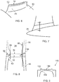
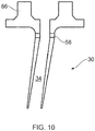
- a radially outer spanwise end of the OGV is connected to a foot 66 which can be bolted or otherwise connected to the outer casing, for example to a mounting ring.
- the aerofoil 30 may be connected to the foot in a similar manner to that previously described for connecting the inner spanwise end of the OGV to the stub of a ring.
- the foot may include a stub similar to that provided on the ring.
- the radially outer spanwise end of the OGV may include a hollow cavity that extends through the foot to a cavity of the OGV. In this example, both ends of the cavity are open ended, so the cavity extends through the foot, OGV and ring.
- the described method of connection permits the thickness of the wall of the aerofoil portion of the vane to be increased in a region proximal to joints with inner and/or outer ring members so as to better deal with transmittal of torsional loads.
- the provision of a hollow region extending through the ring and/or foot to the cavity of the aerofoil means that the weight penalty of having increased wall thickness can be reduced.
- a projection on the cover aids in the manufacturing process because it aids location of the aerofoil on the stub and it prevents or reduces splatter onto the inner walls of the aerofoil during the welding process, which can create stress raisers.
- the projection is a close fit to the cavity, the risk of voids forming in the weld can be reduced.
- the risk of voids forming in the weld can be further reduced by provision of increased wall thickness in the region of the weld.
- the radius applied to the leading edge and trailing edge of the cavity can reduce the risk of voids forming in the weld between the aerofoil and the stub.
- the stubs are provided on a ring that is defined by a single annulus member, but in alternative embodiments the ring may be defined by a plurality of arcuate members.
- the aerofoil is manufactured using diffusion bonding and hot creep forming, but in alternative embodiments the aerofoil may be made using any other known manufacturing methods.
- an aerofoil and support member with a hollow cavity that extends through the support member to the aerofoil may be manufactured without the need to weld the aerofoil to the support member, for example using additive layer manufacturing techniques.
Landscapes
- Engineering & Computer Science (AREA)
- Mechanical Engineering (AREA)
- General Engineering & Computer Science (AREA)
- Architecture (AREA)
- Structures Of Non-Positive Displacement Pumps (AREA)
- Turbine Rotor Nozzle Sealing (AREA)
Applications Claiming Priority (1)
| Application Number | Priority Date | Filing Date | Title |
|---|---|---|---|
| GBGB1707101.0A GB201707101D0 (en) | 2017-05-04 | 2017-05-04 | Vane arrangement for a gas turbine engine |
Publications (2)
| Publication Number | Publication Date |
|---|---|
| EP3399146A1 true EP3399146A1 (fr) | 2018-11-07 |
| EP3399146B1 EP3399146B1 (fr) | 2020-06-03 |
Family
ID=59065485
Family Applications (1)
| Application Number | Title | Priority Date | Filing Date |
|---|---|---|---|
| EP18165732.1A Active EP3399146B1 (fr) | 2017-05-04 | 2018-04-04 | Procede de fabrication d'un ensemble d'aube pour moteur de turbine à gaz |
Country Status (3)
| Country | Link |
|---|---|
| US (1) | US10689990B2 (fr) |
| EP (1) | EP3399146B1 (fr) |
| GB (1) | GB201707101D0 (fr) |
Cited By (2)
| Publication number | Priority date | Publication date | Assignee | Title |
|---|---|---|---|---|
| WO2020165096A1 (fr) * | 2019-02-15 | 2020-08-20 | Siemens Aktiengesellschaft | Aube mobile pour machine tournante thermique et procédé de fabrication d'une telle aube mobile |
| WO2022171240A1 (fr) * | 2021-02-12 | 2022-08-18 | MTU Aero Engines AG | Procédé de production d'une structure d'écoulement pour une turbomachine |
Families Citing this family (1)
| Publication number | Priority date | Publication date | Assignee | Title |
|---|---|---|---|---|
| US12253003B1 (en) * | 2023-08-21 | 2025-03-18 | Rtx Corporation | Integral stator vane weld shield |
Citations (6)
| Publication number | Priority date | Publication date | Assignee | Title |
|---|---|---|---|---|
| WO2005116405A1 (fr) * | 2004-05-27 | 2005-12-08 | Volvo Aero Corporation | Structure de support dans un dispositif a turbine ou a compresseur et procede pour monter la structure |
| WO2009157817A1 (fr) * | 2008-06-26 | 2009-12-30 | Volvo Aero Corporation | Ensemble aube, procédé de fabrication associé, et turbomachine équipée de cet ensemble aube |
| WO2014067868A1 (fr) * | 2012-10-31 | 2014-05-08 | Nuovo Pignone Srl | Procédés de fabrication d'aubes de turbomachines par usinage par étincelage, aubes et turbomachines |
| WO2014158284A2 (fr) * | 2013-03-14 | 2014-10-02 | Freeman Ted J | Aube de turbine coulée en deux fois |
| FR3029238A1 (fr) * | 2014-11-27 | 2016-06-03 | Snecma | Ensemble pour turbomachine comprenant des bras rayonnants soudes a une piece circulaire |
| FR3036734A1 (fr) * | 2015-05-28 | 2016-12-02 | Snecma | Bras de carter de turbomachine |
Family Cites Families (13)
| Publication number | Priority date | Publication date | Assignee | Title |
|---|---|---|---|---|
| US2888243A (en) | 1956-10-22 | 1959-05-26 | Pollock Robert Stephen | Cooled turbine blade |
| DE1174329B (de) | 1959-08-24 | 1964-07-23 | Zakl Mech Im Gen K S | Leitradzwischenboden fuer Dampf- oder Gasturbinen |
| JPS62118973A (ja) | 1985-11-18 | 1987-05-30 | Kawasaki Steel Corp | 鋼管内周面への溶断スパツタ−の付着防止方法 |
| US4883216A (en) | 1988-03-28 | 1989-11-28 | General Electric Company | Method for bonding an article projection |
| US4944444A (en) | 1989-06-22 | 1990-07-31 | Mk-Ferguson Company | Welding or burning shield |
| US5755031A (en) | 1996-11-12 | 1998-05-26 | United Technologies Corporation | Method for attaching a rotor blade to an integrally bladed rotor |
| DE19831736C2 (de) | 1998-07-15 | 2000-05-31 | Mtu Muenchen Gmbh | Verfahren zur Reparatur und Herstellung eines integral beschaufelten Rotors für eine Strömungsmaschine |
| US6394750B1 (en) | 2000-04-03 | 2002-05-28 | United Technologies Corporation | Method and detail for processing a stator vane |
| US20030106215A1 (en) | 2001-12-11 | 2003-06-12 | General Electric Company | Turbine nozzle segment and method of repairing same |
| US6844520B2 (en) | 2002-09-26 | 2005-01-18 | General Electric Company | Methods for fabricating gas turbine engine combustors |
| GB2397855B (en) * | 2003-01-30 | 2006-04-05 | Rolls Royce Plc | A turbomachine aerofoil |
| US8096758B2 (en) | 2008-09-03 | 2012-01-17 | Siemens Energy, Inc. | Circumferential shroud inserts for a gas turbine vane platform |
| CN204209295U (zh) | 2014-09-28 | 2015-03-18 | 常州市常光波纹管业有限公司 | 一种圆形钢管焊渣回收装置 |
-
2017
- 2017-05-04 GB GBGB1707101.0A patent/GB201707101D0/en not_active Ceased
-
2018
- 2018-04-04 EP EP18165732.1A patent/EP3399146B1/fr active Active
- 2018-05-02 US US15/969,167 patent/US10689990B2/en active Active
Patent Citations (6)
| Publication number | Priority date | Publication date | Assignee | Title |
|---|---|---|---|---|
| WO2005116405A1 (fr) * | 2004-05-27 | 2005-12-08 | Volvo Aero Corporation | Structure de support dans un dispositif a turbine ou a compresseur et procede pour monter la structure |
| WO2009157817A1 (fr) * | 2008-06-26 | 2009-12-30 | Volvo Aero Corporation | Ensemble aube, procédé de fabrication associé, et turbomachine équipée de cet ensemble aube |
| WO2014067868A1 (fr) * | 2012-10-31 | 2014-05-08 | Nuovo Pignone Srl | Procédés de fabrication d'aubes de turbomachines par usinage par étincelage, aubes et turbomachines |
| WO2014158284A2 (fr) * | 2013-03-14 | 2014-10-02 | Freeman Ted J | Aube de turbine coulée en deux fois |
| FR3029238A1 (fr) * | 2014-11-27 | 2016-06-03 | Snecma | Ensemble pour turbomachine comprenant des bras rayonnants soudes a une piece circulaire |
| FR3036734A1 (fr) * | 2015-05-28 | 2016-12-02 | Snecma | Bras de carter de turbomachine |
Cited By (2)
| Publication number | Priority date | Publication date | Assignee | Title |
|---|---|---|---|---|
| WO2020165096A1 (fr) * | 2019-02-15 | 2020-08-20 | Siemens Aktiengesellschaft | Aube mobile pour machine tournante thermique et procédé de fabrication d'une telle aube mobile |
| WO2022171240A1 (fr) * | 2021-02-12 | 2022-08-18 | MTU Aero Engines AG | Procédé de production d'une structure d'écoulement pour une turbomachine |
Also Published As
| Publication number | Publication date |
|---|---|
| US20180320534A1 (en) | 2018-11-08 |
| EP3399146B1 (fr) | 2020-06-03 |
| US10689990B2 (en) | 2020-06-23 |
| GB201707101D0 (en) | 2017-06-21 |
Similar Documents
| Publication | Publication Date | Title |
|---|---|---|
| US10675716B2 (en) | Vane arrangement for a gas turbine engine | |
| EP1890008B1 (fr) | Aube de rotor | |
| EP3431713B1 (fr) | Rotor à aubage intégral et moteur à turbine à gaz associé | |
| US10808543B2 (en) | Rotors with modulus mistuned airfoils | |
| US10815798B2 (en) | Turbine engine blade with leading edge strip | |
| EP1120543A2 (fr) | Méthode et dispositif d'alimentation en air pour l'intérieur d'un rotor d'un compresseur | |
| EP0719907A1 (fr) | Virole pour turbine à gaz | |
| EP2000631A2 (fr) | Rotor aubagé et procédé de fabrication associé | |
| EP3399146B1 (fr) | Procede de fabrication d'un ensemble d'aube pour moteur de turbine à gaz | |
| US20060280610A1 (en) | Turbine blade and method of fabricating same | |
| EP3498971B1 (fr) | Profil d'aube pour moteur à turbine à gaz comprenant une feuille de division | |
| KR102763647B1 (ko) | 터빈 블레이드 팁 냉각 홀 공급 플리넘 | |
| EP2938832B1 (fr) | Aube de turbine renforcée avec coin coupé | |
| EP1818503A2 (fr) | Aube de turbine dotée d'un plénum de réduction de poids | |
| EP3550111B1 (fr) | Carénage d'aube de turbine pour moteur à turbine à gaz comportant une turbine de puissance et son procédé de fabrication | |
| US11060410B2 (en) | Method of forming a protective sheath for an aerofoil component | |
| EP3287601A1 (fr) | Aube de soufflante non linéaire en plusieurs parties | |
| US12305533B2 (en) | Turbine rotor dovetail structure with splines | |
| EP4512999A1 (fr) | Structure en queue d'aronde de rotor de turbine avec cannelures | |
| EP3639970A1 (fr) | Fabrication d'aube directrice de sortie de ventilateur | |
| US20210270140A1 (en) | An Aerofoil Structure and a Method of Manufacturing an Aerofoil Structure for a Gas Turbine Engine | |
| EP4553293A1 (fr) | Entretoise pour ensemble palier et procédé de retrait d'entretoise | |
| EP3581761A1 (fr) | Procédé de formation d'une surface portante | |
| EP3059389A1 (fr) | Disque de rotor d'une turbine á gaz avec rainure circonférentielle asymmétrique |
Legal Events
| Date | Code | Title | Description |
|---|---|---|---|
| PUAI | Public reference made under article 153(3) epc to a published international application that has entered the european phase |
Free format text: ORIGINAL CODE: 0009012 |
|
| STAA | Information on the status of an ep patent application or granted ep patent |
Free format text: STATUS: THE APPLICATION HAS BEEN PUBLISHED |
|
| AK | Designated contracting states |
Kind code of ref document: A1 Designated state(s): AL AT BE BG CH CY CZ DE DK EE ES FI FR GB GR HR HU IE IS IT LI LT LU LV MC MK MT NL NO PL PT RO RS SE SI SK SM TR |
|
| AX | Request for extension of the european patent |
Extension state: BA ME |
|
| STAA | Information on the status of an ep patent application or granted ep patent |
Free format text: STATUS: REQUEST FOR EXAMINATION WAS MADE |
|
| 17P | Request for examination filed |
Effective date: 20190109 |
|
| RBV | Designated contracting states (corrected) |
Designated state(s): AL AT BE BG CH CY CZ DE DK EE ES FI FR GB GR HR HU IE IS IT LI LT LU LV MC MK MT NL NO PL PT RO RS SE SI SK SM TR |
|
| RIC1 | Information provided on ipc code assigned before grant |
Ipc: F01D 5/18 20060101AFI20191025BHEP Ipc: B23P 15/04 20060101ALI20191025BHEP Ipc: F01D 9/04 20060101ALI20191025BHEP |
|
| GRAP | Despatch of communication of intention to grant a patent |
Free format text: ORIGINAL CODE: EPIDOSNIGR1 |
|
| STAA | Information on the status of an ep patent application or granted ep patent |
Free format text: STATUS: GRANT OF PATENT IS INTENDED |
|
| INTG | Intention to grant announced |
Effective date: 20191206 |
|
| RAP1 | Party data changed (applicant data changed or rights of an application transferred) |
Owner name: ROLLS-ROYCE PLC |
|
| GRAS | Grant fee paid |
Free format text: ORIGINAL CODE: EPIDOSNIGR3 |
|
| GRAA | (expected) grant |
Free format text: ORIGINAL CODE: 0009210 |
|
| STAA | Information on the status of an ep patent application or granted ep patent |
Free format text: STATUS: THE PATENT HAS BEEN GRANTED |
|
| AK | Designated contracting states |
Kind code of ref document: B1 Designated state(s): AL AT BE BG CH CY CZ DE DK EE ES FI FR GB GR HR HU IE IS IT LI LT LU LV MC MK MT NL NO PL PT RO RS SE SI SK SM TR |
|
| REG | Reference to a national code |
Ref country code: GB Ref legal event code: FG4D |
|
| REG | Reference to a national code |
Ref country code: CH Ref legal event code: EP Ref country code: AT Ref legal event code: REF Ref document number: 1277212 Country of ref document: AT Kind code of ref document: T Effective date: 20200615 |
|
| REG | Reference to a national code |
Ref country code: DE Ref legal event code: R096 Ref document number: 602018004976 Country of ref document: DE |
|
| REG | Reference to a national code |
Ref country code: LT Ref legal event code: MG4D |
|
| PG25 | Lapsed in a contracting state [announced via postgrant information from national office to epo] |
Ref country code: SE Free format text: LAPSE BECAUSE OF FAILURE TO SUBMIT A TRANSLATION OF THE DESCRIPTION OR TO PAY THE FEE WITHIN THE PRESCRIBED TIME-LIMIT Effective date: 20200603 Ref country code: NO Free format text: LAPSE BECAUSE OF FAILURE TO SUBMIT A TRANSLATION OF THE DESCRIPTION OR TO PAY THE FEE WITHIN THE PRESCRIBED TIME-LIMIT Effective date: 20200903 Ref country code: FI Free format text: LAPSE BECAUSE OF FAILURE TO SUBMIT A TRANSLATION OF THE DESCRIPTION OR TO PAY THE FEE WITHIN THE PRESCRIBED TIME-LIMIT Effective date: 20200603 Ref country code: LT Free format text: LAPSE BECAUSE OF FAILURE TO SUBMIT A TRANSLATION OF THE DESCRIPTION OR TO PAY THE FEE WITHIN THE PRESCRIBED TIME-LIMIT Effective date: 20200603 Ref country code: GR Free format text: LAPSE BECAUSE OF FAILURE TO SUBMIT A TRANSLATION OF THE DESCRIPTION OR TO PAY THE FEE WITHIN THE PRESCRIBED TIME-LIMIT Effective date: 20200904 |
|
| REG | Reference to a national code |
Ref country code: NL Ref legal event code: MP Effective date: 20200603 |
|
| PG25 | Lapsed in a contracting state [announced via postgrant information from national office to epo] |
Ref country code: BG Free format text: LAPSE BECAUSE OF FAILURE TO SUBMIT A TRANSLATION OF THE DESCRIPTION OR TO PAY THE FEE WITHIN THE PRESCRIBED TIME-LIMIT Effective date: 20200903 Ref country code: LV Free format text: LAPSE BECAUSE OF FAILURE TO SUBMIT A TRANSLATION OF THE DESCRIPTION OR TO PAY THE FEE WITHIN THE PRESCRIBED TIME-LIMIT Effective date: 20200603 Ref country code: HR Free format text: LAPSE BECAUSE OF FAILURE TO SUBMIT A TRANSLATION OF THE DESCRIPTION OR TO PAY THE FEE WITHIN THE PRESCRIBED TIME-LIMIT Effective date: 20200603 Ref country code: RS Free format text: LAPSE BECAUSE OF FAILURE TO SUBMIT A TRANSLATION OF THE DESCRIPTION OR TO PAY THE FEE WITHIN THE PRESCRIBED TIME-LIMIT Effective date: 20200603 |
|
| REG | Reference to a national code |
Ref country code: AT Ref legal event code: MK05 Ref document number: 1277212 Country of ref document: AT Kind code of ref document: T Effective date: 20200603 |
|
| PG25 | Lapsed in a contracting state [announced via postgrant information from national office to epo] |
Ref country code: NL Free format text: LAPSE BECAUSE OF FAILURE TO SUBMIT A TRANSLATION OF THE DESCRIPTION OR TO PAY THE FEE WITHIN THE PRESCRIBED TIME-LIMIT Effective date: 20200603 Ref country code: AL Free format text: LAPSE BECAUSE OF FAILURE TO SUBMIT A TRANSLATION OF THE DESCRIPTION OR TO PAY THE FEE WITHIN THE PRESCRIBED TIME-LIMIT Effective date: 20200603 |
|
| PG25 | Lapsed in a contracting state [announced via postgrant information from national office to epo] |
Ref country code: SM Free format text: LAPSE BECAUSE OF FAILURE TO SUBMIT A TRANSLATION OF THE DESCRIPTION OR TO PAY THE FEE WITHIN THE PRESCRIBED TIME-LIMIT Effective date: 20200603 Ref country code: EE Free format text: LAPSE BECAUSE OF FAILURE TO SUBMIT A TRANSLATION OF THE DESCRIPTION OR TO PAY THE FEE WITHIN THE PRESCRIBED TIME-LIMIT Effective date: 20200603 Ref country code: AT Free format text: LAPSE BECAUSE OF FAILURE TO SUBMIT A TRANSLATION OF THE DESCRIPTION OR TO PAY THE FEE WITHIN THE PRESCRIBED TIME-LIMIT Effective date: 20200603 Ref country code: PT Free format text: LAPSE BECAUSE OF FAILURE TO SUBMIT A TRANSLATION OF THE DESCRIPTION OR TO PAY THE FEE WITHIN THE PRESCRIBED TIME-LIMIT Effective date: 20201006 Ref country code: IT Free format text: LAPSE BECAUSE OF FAILURE TO SUBMIT A TRANSLATION OF THE DESCRIPTION OR TO PAY THE FEE WITHIN THE PRESCRIBED TIME-LIMIT Effective date: 20200603 Ref country code: RO Free format text: LAPSE BECAUSE OF FAILURE TO SUBMIT A TRANSLATION OF THE DESCRIPTION OR TO PAY THE FEE WITHIN THE PRESCRIBED TIME-LIMIT Effective date: 20200603 Ref country code: ES Free format text: LAPSE BECAUSE OF FAILURE TO SUBMIT A TRANSLATION OF THE DESCRIPTION OR TO PAY THE FEE WITHIN THE PRESCRIBED TIME-LIMIT Effective date: 20200603 Ref country code: CZ Free format text: LAPSE BECAUSE OF FAILURE TO SUBMIT A TRANSLATION OF THE DESCRIPTION OR TO PAY THE FEE WITHIN THE PRESCRIBED TIME-LIMIT Effective date: 20200603 |
|
| PG25 | Lapsed in a contracting state [announced via postgrant information from national office to epo] |
Ref country code: PL Free format text: LAPSE BECAUSE OF FAILURE TO SUBMIT A TRANSLATION OF THE DESCRIPTION OR TO PAY THE FEE WITHIN THE PRESCRIBED TIME-LIMIT Effective date: 20200603 Ref country code: SK Free format text: LAPSE BECAUSE OF FAILURE TO SUBMIT A TRANSLATION OF THE DESCRIPTION OR TO PAY THE FEE WITHIN THE PRESCRIBED TIME-LIMIT Effective date: 20200603 Ref country code: IS Free format text: LAPSE BECAUSE OF FAILURE TO SUBMIT A TRANSLATION OF THE DESCRIPTION OR TO PAY THE FEE WITHIN THE PRESCRIBED TIME-LIMIT Effective date: 20201003 |
|
| REG | Reference to a national code |
Ref country code: DE Ref legal event code: R097 Ref document number: 602018004976 Country of ref document: DE |
|
| PLBE | No opposition filed within time limit |
Free format text: ORIGINAL CODE: 0009261 |
|
| STAA | Information on the status of an ep patent application or granted ep patent |
Free format text: STATUS: NO OPPOSITION FILED WITHIN TIME LIMIT |
|
| PG25 | Lapsed in a contracting state [announced via postgrant information from national office to epo] |
Ref country code: DK Free format text: LAPSE BECAUSE OF FAILURE TO SUBMIT A TRANSLATION OF THE DESCRIPTION OR TO PAY THE FEE WITHIN THE PRESCRIBED TIME-LIMIT Effective date: 20200603 |
|
| 26N | No opposition filed |
Effective date: 20210304 |
|
| PG25 | Lapsed in a contracting state [announced via postgrant information from national office to epo] |
Ref country code: SI Free format text: LAPSE BECAUSE OF FAILURE TO SUBMIT A TRANSLATION OF THE DESCRIPTION OR TO PAY THE FEE WITHIN THE PRESCRIBED TIME-LIMIT Effective date: 20200603 |
|
| PG25 | Lapsed in a contracting state [announced via postgrant information from national office to epo] |
Ref country code: MC Free format text: LAPSE BECAUSE OF FAILURE TO SUBMIT A TRANSLATION OF THE DESCRIPTION OR TO PAY THE FEE WITHIN THE PRESCRIBED TIME-LIMIT Effective date: 20200603 |
|
| PG25 | Lapsed in a contracting state [announced via postgrant information from national office to epo] |
Ref country code: LU Free format text: LAPSE BECAUSE OF NON-PAYMENT OF DUE FEES Effective date: 20210404 |
|
| REG | Reference to a national code |
Ref country code: BE Ref legal event code: MM Effective date: 20210430 |
|
| PG25 | Lapsed in a contracting state [announced via postgrant information from national office to epo] |
Ref country code: CH Free format text: LAPSE BECAUSE OF NON-PAYMENT OF DUE FEES Effective date: 20210430 Ref country code: LI Free format text: LAPSE BECAUSE OF NON-PAYMENT OF DUE FEES Effective date: 20210430 |
|
| PG25 | Lapsed in a contracting state [announced via postgrant information from national office to epo] |
Ref country code: IE Free format text: LAPSE BECAUSE OF NON-PAYMENT OF DUE FEES Effective date: 20210404 |
|
| PG25 | Lapsed in a contracting state [announced via postgrant information from national office to epo] |
Ref country code: IS Free format text: LAPSE BECAUSE OF FAILURE TO SUBMIT A TRANSLATION OF THE DESCRIPTION OR TO PAY THE FEE WITHIN THE PRESCRIBED TIME-LIMIT Effective date: 20201003 |
|
| PG25 | Lapsed in a contracting state [announced via postgrant information from national office to epo] |
Ref country code: BE Free format text: LAPSE BECAUSE OF NON-PAYMENT OF DUE FEES Effective date: 20210430 |
|
| PG25 | Lapsed in a contracting state [announced via postgrant information from national office to epo] |
Ref country code: CY Free format text: LAPSE BECAUSE OF FAILURE TO SUBMIT A TRANSLATION OF THE DESCRIPTION OR TO PAY THE FEE WITHIN THE PRESCRIBED TIME-LIMIT Effective date: 20200603 |
|
| P01 | Opt-out of the competence of the unified patent court (upc) registered |
Effective date: 20230528 |
|
| PG25 | Lapsed in a contracting state [announced via postgrant information from national office to epo] |
Ref country code: HU Free format text: LAPSE BECAUSE OF FAILURE TO SUBMIT A TRANSLATION OF THE DESCRIPTION OR TO PAY THE FEE WITHIN THE PRESCRIBED TIME-LIMIT; INVALID AB INITIO Effective date: 20180404 |
|
| PG25 | Lapsed in a contracting state [announced via postgrant information from national office to epo] |
Ref country code: MK Free format text: LAPSE BECAUSE OF FAILURE TO SUBMIT A TRANSLATION OF THE DESCRIPTION OR TO PAY THE FEE WITHIN THE PRESCRIBED TIME-LIMIT Effective date: 20200603 |
|
| PG25 | Lapsed in a contracting state [announced via postgrant information from national office to epo] |
Ref country code: MT Free format text: LAPSE BECAUSE OF FAILURE TO SUBMIT A TRANSLATION OF THE DESCRIPTION OR TO PAY THE FEE WITHIN THE PRESCRIBED TIME-LIMIT Effective date: 20200603 |
|
| PGFP | Annual fee paid to national office [announced via postgrant information from national office to epo] |
Ref country code: DE Payment date: 20250428 Year of fee payment: 8 |
|
| PGFP | Annual fee paid to national office [announced via postgrant information from national office to epo] |
Ref country code: FR Payment date: 20250424 Year of fee payment: 8 |
|
| PG25 | Lapsed in a contracting state [announced via postgrant information from national office to epo] |
Ref country code: TR Free format text: LAPSE BECAUSE OF FAILURE TO SUBMIT A TRANSLATION OF THE DESCRIPTION OR TO PAY THE FEE WITHIN THE PRESCRIBED TIME-LIMIT Effective date: 20200603 |
|
| PGFP | Annual fee paid to national office [announced via postgrant information from national office to epo] |
Ref country code: GB Payment date: 20260313 Year of fee payment: 9 |