EP3399185A1 - Einhausung für eine gondel einer windenergieanlage - Google Patents
Einhausung für eine gondel einer windenergieanlage Download PDFInfo
- Publication number
- EP3399185A1 EP3399185A1 EP18170489.1A EP18170489A EP3399185A1 EP 3399185 A1 EP3399185 A1 EP 3399185A1 EP 18170489 A EP18170489 A EP 18170489A EP 3399185 A1 EP3399185 A1 EP 3399185A1
- Authority
- EP
- European Patent Office
- Prior art keywords
- panel
- substructure
- section
- roof
- roof panel
- Prior art date
- Legal status (The legal status is an assumption and is not a legal conclusion. Google has not performed a legal analysis and makes no representation as to the accuracy of the status listed.)
- Granted
Links
Images


Classifications
-
- F—MECHANICAL ENGINEERING; LIGHTING; HEATING; WEAPONS; BLASTING
- F03—MACHINES OR ENGINES FOR LIQUIDS; WIND, SPRING, OR WEIGHT MOTORS; PRODUCING MECHANICAL POWER OR A REACTIVE PROPULSIVE THRUST, NOT OTHERWISE PROVIDED FOR
- F03D—WIND MOTORS
- F03D80/00—Details, components or accessories not provided for in groups F03D1/00 - F03D17/00
-
- F—MECHANICAL ENGINEERING; LIGHTING; HEATING; WEAPONS; BLASTING
- F03—MACHINES OR ENGINES FOR LIQUIDS; WIND, SPRING, OR WEIGHT MOTORS; PRODUCING MECHANICAL POWER OR A REACTIVE PROPULSIVE THRUST, NOT OTHERWISE PROVIDED FOR
- F03D—WIND MOTORS
- F03D13/00—Assembly, mounting or commissioning of wind motors; Arrangements specially adapted for transporting wind motor components
- F03D13/10—Assembly of wind motors; Arrangements for erecting wind motors
-
- F—MECHANICAL ENGINEERING; LIGHTING; HEATING; WEAPONS; BLASTING
- F03—MACHINES OR ENGINES FOR LIQUIDS; WIND, SPRING, OR WEIGHT MOTORS; PRODUCING MECHANICAL POWER OR A REACTIVE PROPULSIVE THRUST, NOT OTHERWISE PROVIDED FOR
- F03D—WIND MOTORS
- F03D1/00—Wind motors with rotation axis substantially parallel to the air flow entering the rotor
-
- F—MECHANICAL ENGINEERING; LIGHTING; HEATING; WEAPONS; BLASTING
- F03—MACHINES OR ENGINES FOR LIQUIDS; WIND, SPRING, OR WEIGHT MOTORS; PRODUCING MECHANICAL POWER OR A REACTIVE PROPULSIVE THRUST, NOT OTHERWISE PROVIDED FOR
- F03D—WIND MOTORS
- F03D80/00—Details, components or accessories not provided for in groups F03D1/00 - F03D17/00
- F03D80/30—Lightning protection
-
- F—MECHANICAL ENGINEERING; LIGHTING; HEATING; WEAPONS; BLASTING
- F03—MACHINES OR ENGINES FOR LIQUIDS; WIND, SPRING, OR WEIGHT MOTORS; PRODUCING MECHANICAL POWER OR A REACTIVE PROPULSIVE THRUST, NOT OTHERWISE PROVIDED FOR
- F03D—WIND MOTORS
- F03D80/00—Details, components or accessories not provided for in groups F03D1/00 - F03D17/00
- F03D80/70—Bearing or lubricating arrangements
-
- F—MECHANICAL ENGINEERING; LIGHTING; HEATING; WEAPONS; BLASTING
- F03—MACHINES OR ENGINES FOR LIQUIDS; WIND, SPRING, OR WEIGHT MOTORS; PRODUCING MECHANICAL POWER OR A REACTIVE PROPULSIVE THRUST, NOT OTHERWISE PROVIDED FOR
- F03D—WIND MOTORS
- F03D80/00—Details, components or accessories not provided for in groups F03D1/00 - F03D17/00
- F03D80/80—Arrangement of components within nacelles or towers
- F03D80/82—Arrangement of components within nacelles or towers of electrical components
-
- F—MECHANICAL ENGINEERING; LIGHTING; HEATING; WEAPONS; BLASTING
- F03—MACHINES OR ENGINES FOR LIQUIDS; WIND, SPRING, OR WEIGHT MOTORS; PRODUCING MECHANICAL POWER OR A REACTIVE PROPULSIVE THRUST, NOT OTHERWISE PROVIDED FOR
- F03D—WIND MOTORS
- F03D80/00—Details, components or accessories not provided for in groups F03D1/00 - F03D17/00
- F03D80/80—Arrangement of components within nacelles or towers
- F03D80/88—Arrangement of components within nacelles or towers of mechanical components
-
- F—MECHANICAL ENGINEERING; LIGHTING; HEATING; WEAPONS; BLASTING
- F05—INDEXING SCHEMES RELATING TO ENGINES OR PUMPS IN VARIOUS SUBCLASSES OF CLASSES F01-F04
- F05B—INDEXING SCHEME RELATING TO WIND, SPRING, WEIGHT, INERTIA OR LIKE MOTORS, TO MACHINES OR ENGINES FOR LIQUIDS COVERED BY SUBCLASSES F03B, F03D AND F03G
- F05B2240/00—Components
- F05B2240/10—Stators
- F05B2240/14—Casings, housings, nacelles, gondels or the like, protecting or supporting assemblies there within
-
- Y—GENERAL TAGGING OF NEW TECHNOLOGICAL DEVELOPMENTS; GENERAL TAGGING OF CROSS-SECTIONAL TECHNOLOGIES SPANNING OVER SEVERAL SECTIONS OF THE IPC; TECHNICAL SUBJECTS COVERED BY FORMER USPC CROSS-REFERENCE ART COLLECTIONS [XRACs] AND DIGESTS
- Y02—TECHNOLOGIES OR APPLICATIONS FOR MITIGATION OR ADAPTATION AGAINST CLIMATE CHANGE
- Y02E—REDUCTION OF GREENHOUSE GAS [GHG] EMISSIONS, RELATED TO ENERGY GENERATION, TRANSMISSION OR DISTRIBUTION
- Y02E10/00—Energy generation through renewable energy sources
- Y02E10/70—Wind energy
- Y02E10/72—Wind turbines with rotation axis in wind direction
Definitions
- the invention relates to an enclosure for a nacelle of a wind turbine.
- the enclosure includes a panel connected to a substructure.
- a nacelle In a wind turbine usually a nacelle is rotatably mounted on a tower.
- the nacelle carries a rotor, which is rotated by the wind and drives a generator to generate electrical energy.
- the rotor By rotating the nacelle relative to the tower, the rotor can be aligned in the wind direction.
- nacelle In the nacelle several components are arranged, such as rotor shaft, gearbox, generator, inverter, control devices, etc.
- An enclosure protects the components arranged in the nacelle from environmental influences.
- the enclosure may be composed of a plurality of panels, EP 2 636 898 A1 .
- the panels can be connected to one another or to the substructure along their edges, so that the overall result is a substantially closed envelope around the nacelle.
- the panels In order for the connection to the substructure and to adjacent panels to fit well, the panels must be manufactured with sufficient precision. Given the large area of the panels and the manufacturing tolerances in steel and fiberglass construction This is not easy, which often requires manual reworking.
- the invention has for its object to present an enclosure for a nacelle of a wind turbine, which can be mounted with reduced effort. Based on the cited prior art, the object is achieved with the features of claim 1. Advantageous embodiments are specified in the dependent claims.
- an imaginary straight line extends across the panel, which is aligned parallel to an edge of the panel.
- the imaginary straight line defines a first partial section of the panel which encompasses the edge.
- the first section abuts on the substructure.
- the first section is held against the substructure by a pulling element acting in a pulling direction. In a direction which intersects the pulling direction, the first section is displaceable relative to the substructure.
- the first section By holding the first section only against the substructure by a pulling element, it is not necessary to position the first section of the panel and the substructure with high precision relative to one another. Rather, the first section can be moved relatively long to the substructure until the arranged in a second portion of the panel fastener can be brought into good engagement. It is therefore a simple installation of the panel possible, even if neither the panel nor the substructure were made in the highest precision.
- the imaginary straight line may intersect two opposing edges of the rectangle.
- the orientation of the imaginary straight line then refers to a third edge, to which the imaginary straight line can extend substantially parallel.
- the first section of the panel defined by the imaginary straight line can make up at least 30%, preferably at least 50%, more preferably at least 80%, of the area of the panel.
- the panel In the second section of the panel, which is arranged on the other side of the imaginary line, the panel can be connected to the substructure via fixed bearings. In the area of a fixed bearing, the panel can not be moved relative to the substructure.
- the attachment may comprise one or more bores formed in the panel which are aligned with corresponding bores in the substructure.
- the connection can be made for example by bolts that extend through the aligned holes therethrough.
- the holes in the panel and / or the holes in the substructure may have a larger diameter in one or more directions than the passed bolts so that the second portion of the panel may be adjusted relative to the substructure. In such an adjustment, only the arranged in the second section fasteners must be noted.
- the first section of the panel can be freely displaced relative to the substructure in the amount required for adjustment.
- the panel may include a plurality of bores for rigid attachment to the substructure that extend along an edge of the panel. This edge of the second Part section may be arranged opposite to the edge of the first section, to which the imaginary straight line is aligned.
- the tension member may extend between the first portion of the panel and an anchoring point of the substructure.
- a displacement of the first section relative to the substructure does not affect too much on the pulling direction of the tension element, it is advantageous if the tension element has a length of at least 10 cm, preferably at least 20 cm.
- the tension element may be formed as a pull rod whose length may be adjustable, for example via a thread. It is also possible to use a pull rope or a tension spring.
- the enclosure may comprise a plurality of tension members extending between the first section and the substructure, for example two tension members, three tension members or four tension members.
- the panel may be stiffened in the area where the tension member engages the panel.
- a stiffening profile may be arranged on an inner side of the panel on which the tension element engages.
- the stiffening profile may extend the length of the panel.
- the panel In the area where there is a rigid connection to the substructure, the panel may, for the purpose of further stiffening, have a standing profile which is angled with respect to the surface of the panel.
- the standing profile may be formed, for example, as a flange, are passed through the screws with which the panel is attached to the substructure.
- One edge of the panel may overlap with another panel.
- the edge in the first section of the Panels to which the imaginary line is aligned overlap with another panel. If the first section abuts on the other panel and the other panel is in turn supported by the substructure, the first section is in accordance with the invention to the substructure.
- An edge in the second section of the panel may additionally or alternatively also overlap with another panel
- the substructure can be carried by a machine carrier of the nacelle.
- Machine carrier refers to a device on which, for example, the rotor shaft, the gearbox or the generator are mounted.
- the substructure may include struts. On the struts attachment points may be formed, on which the panel is attached or on which the panel rests. The struts may extend substantially parallel to the panel.
- the panel may be a side panel, a panel that forms a side wall of the enclosure.
- the first section may form a lower section of the side panel.
- the second section may form an upper section of the side panel.
- the imaginary straight line may extend substantially horizontally and parallel to a longitudinal axis of the nacelle.
- a roof panel can connect to the side panel.
- the roof panel may include a side portion that overlaps the upper portion of the side panel.
- the overlap may be rainproof, so that coming from the roof panel rainwater can not penetrate the transition between the roof panel and the side panel in the interior of the enclosure.
- Between the side section of the Roof panel and the upper portion of the side panel may be formed a gap, so that the roof panel and the side panel can move relative to each other in this area.
- the roof panel may extend over the entire width of the enclosure and connect at its other end to a side panel disposed on the opposite side.
- the roof panel may be attached to the substructure via one or more bearings.
- a bearing row formed by the bearings of the roof panel may extend substantially parallel to a bearing row of the side panel.
- the roof panel bearings can include fixed and plain bearings. For example, if the roof panel comprises three bearings adjacent to a side panel, two bearings may be formed as a fixed bearing and a bearing as a sliding bearing.
- the plain bearing may be the foremost bearing, that is, the bearing closest to the rotor.
- the roof panel may be composed of a plurality of panel parts.
- a roof panel may for example comprise two, three or four panel parts.
- the panel parts can extend over the entire width of the enclosure.
- the panel parts can be arranged one behind the other in the longitudinal direction. Between two adjacent panel parts, a flange may be formed. In the flange bores may be formed so that the panel parts can be connected for example with screws.
- One or more bearings, with which the roof panel is mounted opposite the substructure, may be arranged in a transition area between a first panel part and a second panel part. The bearings can be designed as a support.
- the roof panel may be held at its rear end, which is remote from the rotor, by a pulling device, which exerts a pull forward.
- the tension element can also be designed as a receptor of a lightning arrester.
- the lightning rod of the wind turbine can extend from a receptor over a distance within the nacelle and a distance within the tower to a grounding point.
- a roof panel may be equipped with technical devices, such as gauges or sensors, that protrude upward above the roof panel.
- technical devices such as gauges or sensors
- these technical facilities can all be accommodated in the same panel part.
- An upwardly projecting device can be designed as a receptor of a lightning arrester.
- a floor panel can connect to the side panel.
- the first section of the side panel may overlap with the floor panel.
- the overlap may be rainproof, so that running water on the side panel at the transition to the floor panel can not penetrate into the interior of the enclosure on the side panel.
- the first section of the side panel may be slidably mounted relative to the floor panel. When the first section of the side panel is pulled inward via a tension member, an outer surface of the floor panel may form an abutment for the train.
- the floor panel can be connected to the substructure via fixed bearings.
- the fixed bearings may be arranged in a row which extends parallel to the lower end of the side panel.
- the floor panel can extend over the entire width of the enclosure and with its other end to a on the opposite side of the enclosure connect adjacent side panel.
- a shell With a roof panel, two side panels and a floor panel, a shell can be formed which extends around the interior of the nacelle.
- the enclosure may include a first side panel and a second side panel disposed longitudinally one behind the other. The first side panel and the second side panel may be slidable relative to one another in the longitudinal direction.
- the first side panel may be connected to a first portion of the substructure
- the second side panel may be connected to a second portion of the substructure.
- the first side panel and the second side panel may be displaceable relative to one another with elastic deformation of the substructure. If the nacelle deforms during operation by bending or torsion, longitudinal displacements between the side panels are permitted relative to one another and thus a forced deformation of the panels and the associated bearing reactions are counteracted.
- the first side panel may overlap longitudinally with the second side panel. In the overlap, preferably the front side panel is arranged on the outside and the rear side panel on the inside. A rear end of the front side panel may be inclined relative to the vertical. An upper portion of the front side panel may extend farther rearward than a lower portion of the front side panel.
- the enclosure may include a first roof panel and a second roof panel.
- the first roof panel may be connected to a first portion of the substructure
- the second roof panel may be connected to a second portion of the substructure.
- the first roof panel and the second roof panel can under elastic deformation of the substructure be relatively movable. Distortions in the operation of the nacelle can thus be absorbed without forces being transmitted between the roof panels.
- Such an enclosure has its own inventive content, regardless of how the connection between the panels and the substructure is designed.
- the two sections of the substructure can be connected to the machine carrier, so that insofar exists a mechanical connection between the two sections of the substructure.
- the substructure, starting from the machine carrier forms a long lever arm, in which there is no mechanical coupling between the sections of the substructure.
- the lever arm may, for example, extend over at least 10%, preferably at least 20%, more preferably at least 50%, of the height that the nacelle has in the area concerned.
- the first roof panel and the second roof panel may be arranged one behind the other in the longitudinal direction.
- the first roof panel and the second roof panel may be slidable relative to one another in the longitudinal direction.
- the first roof panel may be an element of a front part facing the rotor
- the second roof panel may be an element of a rear part of the enclosure.
- the front part and / or the rear part may comprise one or more side panels.
- the front part and / or the rear part may extend in the circumferential direction around the interior of the nacelle around and each comprise a roof panel, two side panels and a floor panel.
- an intermediate panel may be arranged.
- the intermediate panel may have a lower height than the roof panel of the front part and the roof panel of the rear part.
- the intermediate panel may have a gutter, so that dripping water is drained from one of the roof panels.
- the gutter may extend transversely so that the water flows sideways.
- the roof panel of the front part and / or the roof panel of the rear part can overlap in the longitudinal direction with the Eisenpaneel.
- the roof panel of the rear part may have a lower height than the roof panel of the front part.
- the invention also relates to a gondola equipped with such an enclosure.
- the invention further relates to a wind turbine with a tower on which such a nacelle is rotatably mounted.
- the nacelle carries a rotor that drives a generator via a rotor shaft.
- a nacelle 14 is rotatably mounted on a tower 15.
- a rotor 16 is rotated by the wind and drives a generator via a gearbox.
- the generator generates electrical power that is fed into an energy distribution network.
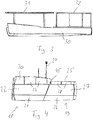
- the gondola 14 has an in Fig. 2 shown enclosure 17, which surrounds the interior of the nacelle 14 and protects the components disposed therein from weather conditions.
- the housing 17 is composed of a front part 18 and a rear part 19.
- the front part 18 comprises a roof panel 20, a floor panel 21 and two side panels 22, of which in Fig. 2 only one is visible.
- the roof panel 18 is composed of four longitudinally successively arranged panel parts 23.
- a first panel part 23 is arranged in front and adjoins an opening of the nacelle 14, which surrounds the rotor hub.
- a second and a third panel part 23 close in the longitudinal direction.
- the rear end of the roof panel 18 forms a fourth panel portion 23.
- the four panel portions 23 are along the in Fig. 2 shown joints with flanges provided and bolted together so that the roof panel 18 can be placed as a unit on the nacelle 14.
- the third panel part 23 is provided with some technical facilities that project upwards over the roof panel 18.
- Two upstanding masts form receptors 24 of a lightning conductor. A lightning striking the receptors 24 is dissipated via a conductor route in the nacelle and in the tower to earth.
- the rear part 19 of the enclosure comprises a roof panel 25, a floor panel 26 and two side panels 27, of which in Fig. 2 only one is visible.
- the roof panel 25 is composed of three successively arranged panel parts 28, along the in Fig. 2 shown joints are bolted together.
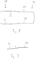
- a machine carrier 30 is arranged, which forms a supporting structure for the components arranged in the nacelle 14. These components include the rotor shaft, that gearbox as well as the generator.
- the machine frame 30 also forms a supporting structure for a front portion 31 of a substructure and a rear portion 32 of a substructure.
- the sections 31, 32 of the substructure are connected to one another via the machine carrier 30, but otherwise mechanically decoupled from one another.
- the front portion 31 of the substructure supports the front part 18 of the housing 17.
- the rear part 32 of the substructure supports the rear part 19 of the housing 17.
- the front part 18 and the rear part 19 of the housing 17 are not connected to each other but can be displaced in the longitudinal direction relative to one another become. This is the back part 19 surrounded from the outside of the front part 18. Since the front part is aligned in the wind direction, there is no gap between the front part 18 and the rear part 19, in which the wind can penetrate directly.
- the side panel 22 of the front part 18 overlaps in the longitudinal direction with the side panel 27 of the rear part 19.
- the overlap has according to Fig. 4 an inclination relative to the vertical and is according to Fig. 9 designed so that rainwater is discharged downwards and does not penetrate into the interior of the nacelle 14.
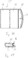
- Fig. 5 a cross section through the rear part 19 of the housing 17 is shown.
- the substructure 32 supports the roof panel 25 via angle plates and thus forms a fixed bearing 33 for the roof panel 25.
- the roof panel is supported in the region of the joints between the panel parts 28 with fixed bearings 33 on the substructure 32.
- the front end of the roof panel 25 is additionally supported with respect to the substructure 32 with a slide bearing displaceable in the longitudinal direction and transverse direction.
- the rear end of the roof panel 25 is held on the substructure 32 via a forwardly acting pulling device 29.
- An outer end of the pulling device 29 also forms a receptor for a lightning rod.
- the side panels 27 are connected to the substructure 32 via screw connections 34 which are arranged adjacent to the fixed bearings 33.
- the lower end of the side panels 27 is pulled inwardly by a pull rod 35 and thus held against the substructure 32.
- a hook 43 is shown, to which the drawbar is hooked.
- the lower end of the side panels 27 is displaceable relative to the substructure 32.
- a screw connection or other rigid connection to the substructure 32 does not exist at the lower end of the side panels 27.
- the only rigid connection between the side panels 27 and the substructure 32 is formed by the screws 34.
- Fig. 12 There is an imaginary straight line, which is aligned with a lower edge 37 of the side panel 27 and which intersects the two lateral edges 38, 39 of the side panel 27.
- the area below the imaginary straight line 36 is referred to as the first section 40 of the side panel 27.
- the area above the imaginary line is referred to as the second section 41 of the side panel 27.
- the first portion 40 significantly more than half of the surface of the side panel 27 from.
- the second section 41 there is a screw 34 between the side panel 27 and the substructure 32.
- the side panel 27 rests with its lower edge on the substructure 32 and is held by tie rods 35 in this position. Other connections between the side panel 27 and the substructure 32 are not present in the first section 40 of the side panel 27.
- the floor panel 26 is connected by screw 42 with the substructure 32. In the middle of the floor panel 26 is additionally suspended with a hanger 44. Between the roof panel 25 and the side panel 27 and between the side panel 27 and the bottom panel 26 there is an overlap, so that rainwater can not penetrate.
- an intermediate panel 45 is disposed at the transition between the rear end of the front roof panel 20 and the front end of the rear roof panel 25, an intermediate panel 45 is disposed.
- the intermediate panel 45 is connected to the rear part 32 of the substructure and has a lower height than the roof panels 20, 25. Both roof panels 20, 25 overlap with the insects, 25. Dripping water is discharged through a rain gutter 46 to the outside.
Landscapes
- Engineering & Computer Science (AREA)
- Life Sciences & Earth Sciences (AREA)
- Sustainable Development (AREA)
- Sustainable Energy (AREA)
- Chemical & Material Sciences (AREA)
- Combustion & Propulsion (AREA)
- Mechanical Engineering (AREA)
- General Engineering & Computer Science (AREA)
- Wind Motors (AREA)
Abstract
Description
- Die Erfindung betrifft eine Einhausung für eine Gondel einer Windenergieanlage. Die Einhausung umfasst ein Paneel, das mit einer Unterkonstruktion verbunden ist.
- Bei einer Windenergieanlage ist üblicherweise eine Gondel drehbar auf einem Turm gelagert. Die Gondel trägt einen Rotor, der durch den Wind in Drehung versetzt wird und einen Generator antreibt, um elektrische Energie zu erzeugen. Durch Rotation der Gondel relativ zu dem Turm kann der Rotor in Windrichtung ausgerichtet werden.
- In der Gondel sind mehrere Komponenten angeordnet, wie beispielsweise Rotorwelle, Getriebe, Generator, Umrichter, Steuereinrichtungen usw. Eine Einhausung schützt die in der Gondel angeordneten Komponenten vor Umwelteinflüssen.
- Die Einhausung kann aus einer Mehrzahl von Paneelen zusammengesetzt sein,
EP 2 636 898 A1 ,WO 2015/155131 A1 . Die Paneele können entlang ihrer Kanten miteinander bzw. mit der Unterkonstruktion verbunden sein, so dass in der Summe eine im Wesentlichen geschlossene Hülle um die Gondel herum entsteht. Damit die Verbindung zu der Unterkonstruktion und zu benachbarten Paneelen gut passt, müssen die Paneele mit einer hinreichenden Präzision gefertigt werden. Angesichts der Großflächigkeit der Paneele sowie der Fertigungstoleranzen im Stahl- und GFK-Bau ist dies nicht ganz einfach, weswegen häufig eine manuelle Nacharbeit erforderlich ist. - Der Erfindung liegt die Aufgabe zugrunde, eine Einhausung für eine Gondel einer Windenergieanlage vorzustellen, die mit vermindertem Aufwand montiert werden kann. Ausgehend vom genannten Stand Technik wird die Aufgabe gelöst mit den Merkmalen des Anspruchs 1. Vorteilhafte Ausführungsformen sind in den Unteransprüchen angegeben.
- Bei dem erfindungsgemäßen Paneel erstreckt sich eine gedachte Gerade über das Paneel, die parallel zu einer Kante des Paneels ausgerichtet ist. Durch die gedachte Gerade wird ein die Kante umfassender erster Teilabschnitt des Paneels definiert. Der erste Teilabschnitt liegt an der Unterkonstruktion an. Der erste Teilabschnitt wird durch ein in einer Zugrichtung wirkendes Zugelement gegen die Unterkonstruktion gehalten. In einer die Zugrichtung schneidenden Richtung ist der erste Teilabschnitt relativ zu der Unterkonstruktion verschiebbar.
- Indem der erste Teilabschnitt lediglich durch ein Zugelement gegen die Unterkonstruktion gehalten wird, ist es nicht erforderlich, den ersten Teilabschnitt des Paneels und die Unterkonstruktion mit hoher Präzision relativ zueinander zu positionieren. Vielmehr kann der erste Teilabschnitt solange relativ auf zu der Unterkonstruktion verschoben werden, bis die in einem zweiten Teilabschnitt des Paneels angeordneten Befestigungsmittel gut in Eingriff gebracht werden können. Es ist demnach eine einfache Montage des Paneels möglich, auch wenn weder das Paneel noch die Unterkonstruktion in höchster Präzision gefertigt wurden.
- Wenn das Paneel eine an ein Rechteck angenäherte Form hat, kann die gedachte Gerade zwei einander gegenüberliegende Kanten des Rechtecks schneiden. Die Ausrichtung der gedachten Geraden bezieht sich dann auf eine dritte Kante, zu der sich die gedachte Gerade im Wesentlichen parallel erstrecken kann. Der durch die gedachte Gerade definierte erste Teilabschnitt des Paneels kann wenigstens 30 %, vorzugsweise wenigstens 50 %, weiter vorzugsweise wenigstens 80 % der Fläche des Paneels ausmachen.
- In dem zweiten Teilabschnitt des Paneels, der auf der anderen Seite der gedachten Geraden angeordnet ist, kann das Paneel über Festlager mit der Unterkonstruktion verbunden sein. Im Bereich eines Festlagers kann das Paneel nicht relativ zu der Unterkonstruktion verschoben werden. Die Befestigung kann eine oder mehrere in dem Paneel ausgebildete Bohrungen umfassen, die mit entsprechenden Bohrungen in der Unterkonstruktion fluchten. Die Verbindung kann beispielsweise durch Schraubbolzen hergestellt werden, die sich durch die fluchtenden Bohrungen hindurch erstrecken. Die Bohrungen in dem Paneel und/oder die Bohrungen in der Unterkonstruktion können in einer oder mehreren Richtungen einen größeren Durchmesser haben als die hindurchgeführten Bolzen, so dass der zweite Teilabschnitt des Paneels relativ zu der Unterkonstruktion justiert werden kann. Bei einer solchen Justierung müssen lediglich die in dem zweiten Teilabschnitt angeordneten Befestigungselemente beachtet werden. Der erste Teilabschnitt des Paneels kann in dem für die Justierung erforderlichen Umfang frei relativ zu der Unterkonstruktion verschoben werden.
- Das Paneel kann für die starre Befestigung an der Unterkonstruktion eine Mehrzahl von Bohrungen umfassen, die sich entlang einer Kante des Paneels erstrecken. Diese Kante des zweiten Teilabschnitts kann gegenüber der Kante des ersten Teilabschnitts angeordnet sein, zu der die gedachte Gerade ausgerichtet ist.
- Das Zugelement kann sich zwischen dem ersten Teilabschnitt des Paneels und einem Verankerungspunkt der Unterkonstruktion erstrecken. Damit eine Verschiebung des ersten Teilabschnitts relativ zu der Unterkonstruktion sich nicht zu stark auf die Zugrichtung des Zugelements auswirkt, ist es von Vorteil, wenn das Zugelement eine Länge von mindestens 10 cm, vorzugsweise mindestens 20 cm hat. Das Zugelement kann als Zugstange ausgebildet sein, deren Länge beispielsweise über ein Gewinde einstellbar sein kann. Möglich ist auch die Verwendung eines Zugseils oder einer Zugfeder. Die Einhausung kann eine Mehrzahl von Zugelementen umfassen, die sich zwischen dem ersten Teilabschnitt und der Unterkonstruktion erstrecken, beispielsweise zwei Zugelemente, drei Zugelemente oder vier Zugelemente.
- Das Paneel kann in dem Bereich, in dem das Zugelement an dem Paneel angreift, versteift sein. Beispielsweise kann ein Versteifungsprofil auf einer Innenseite des Paneels angeordnet sein, an dem das Zugelement angreift. Das Versteifungsprofil kann sich über die Länge des Paneels erstrecken. In dem Bereich, in dem eine starre Verbindung zur Unterkonstruktion besteht, kann das Paneel zum Zwecke der weiteren Versteifung ein stehendes Profil aufweisen, das gegenüber der Fläche des Paneels abgewinkelt ist. Das stehende Profil kann beispielsweise als Flansch ausgebildet sein, durch den Schrauben hindurchgeführt sind, mit denen das Paneel an der Unterkonstruktion befestigt ist.
- Eine Kante des Paneels kann mit einem weiteren Paneel überlappen. Insbesondere kann die Kante im ersten Teilabschnitt des Paneels, zu der die gedachte Gerade ausgerichtet ist, mit einem anderen Paneel überlappen. Liegt der erste Teilabschnitt an dem anderen Paneel an und ist das andere Paneel seinerseits durch die Unterkonstruktion getragen, so liegt der erste Teilabschnitt im Sinne der Erfindung an der Unterkonstruktion an. Eine Kante im zweiten Teilabschnitt des Paneels kann zusätzlich oder alternativ dazu ebenfalls mit einem weiteren Paneel überlappen
- Die Unterkonstruktion kann von einem Maschinenträger der Gondel getragen werden. Maschinenträger bezeichnet eine Einrichtung, auf der beispielsweise die Rotorwelle, das Getriebe oder der Generator gelagert sind. Die Unterkonstruktion kann Streben umfassen. An den Streben können Befestigungspunkte ausgebildet sein, an denen das Paneel befestigt ist oder an denen das Paneel aufliegt. Die Streben können sich im Wesentlichen parallel zu dem Paneel erstrecken.
- Das Paneel kann ein Seitenpaneel sein, also ein Paneel, das eine Seitenwand der Einhausung bildet. Der erste Teilabschnitt kann einen unteren Abschnitt des Seitenpaneels bilden. Der zweite Teilabschnitt kann einen oberen Abschnitt des Seitenpaneels bilden. Die gedachte Gerade kann sich im Wesentlichen horizontal und parallel zu einer Längsachse der Gondel erstrecken.
- Nach oben hin kann ein Dachpaneel an das Seitenpaneel anschließen. Das Dachpaneel kann einen Seitenabschnitt umfassen, der mit dem oberen Abschnitt des Seitenpaneels überlappt. Die Überlappung kann regendicht ausgebildet sein, so dass von dem Dachpaneel kommendes Regenwasser nicht am Übergang zwischen dem Dachpaneel und dem Seitenpaneel in den Innenraum der Einhausung eindringen kann. Zwischen dem Seitenabschnitt des Dachpaneels und dem oberen Abschnitt des Seitenpaneels kann ein Spalt ausgebildet sein, so dass das Dachpaneel und das Seitenpaneel sich in diesem Bereich relativ zueinander bewegen können.
- Das Dachpaneel kann sich über die gesamte Breite der Einhausung erstrecken und an seinem anderen Ende an ein auf der gegenüberliegenden Seite angeordnetes Seitenpaneel anschließen.
- Das Dachpaneel kann über eines oder mehrere Lager an der Unterkonstruktion befestigt sein. Eine durch die Lager des Dachpaneels gebildete Lagerreihe kann sich im Wesentlichen parallel zu einer Lagerreihe des Seitenpaneels erstrecken. Die Lager des Dachpaneels können Festlager und Gleitlager umfassen. Umfasst das Dachpaneel beispielsweise drei zu einem Seitenpaneel benachbarte Lager, so können zwei Lager als Festlager und ein Lager als Gleitlager ausgebildet sein. Das Gleitlager kann das vorderste Lager sein, also das am nächsten zum Rotor angeordnete Lager.
- Das Dachpaneel kann aus einer Mehrzahl von Paneelteilen zusammengesetzt sein. Ein Dachpaneel kann beispielsweise zwei, drei oder vier Paneelteile umfassen. Die Paneelteile können sich über die gesamte Breite der Einhausung erstrecken. Die Paneelteile können in Längsrichtung hintereinander angeordnet sein. Zwischen zwei benachbarten Paneelteilen kann ein Flansch ausgebildet sein. In dem Flansch können Bohrungen ausgebildet sein, so dass die Paneelteile beispielsweise mit Schrauben verbunden werden können. Eines oder mehrere Lager, mit denen das Dachpaneel gegenüber der Unterkonstruktion gelagert ist, können in einem Übergangsbereich zwischen einem ersten Paneelteile und einem zweiten Paneelteil angeordnet sein. Die Lager können als Auflager gestaltet sein.
- Das Dachpaneel kann an seinem hinteren Ende, das von dem Rotor abgewandt ist, durch eine Zugeinrichtung gehalten ist, die einen Zug nach vorne ausübt. Das Zugelement kann zugleich als Rezeptor eines Blitzableiters ausgebildet sein. Der Blitzableiter der Windenergieanlage kann sich von einem Rezeptor über eine Strecke innerhalb der Gondel und eine Strecke innerhalb des Turms bis zu einem Erdungspunkt erstrecken.
- Ein Dachpaneel kann mit technischen Einrichtungen ausgestattet sein, wie beispielsweise Messgeräten oder Sensoren, die nach oben über das Dachpaneel hinausragen. Bei einem aus mehreren Paneelteilen zusammengesetzten Dachpaneel können diese technischen Einrichtungen allesamt in demselben Paneelteil untergebracht sein. Eine nach oben ragende Einrichtung kann als Rezeptor eines Blitzableiters ausgebildet sein.
- Nach unten hin kann ein Bodenpaneel an das Seitenpaneel anschließen. Der erste Teilabschnitt des Seitenpaneels kann mit dem Bodenpaneel überlappen. Die Überlappung kann regendicht ausgebildet sein, so dass an dem Seitenpaneel herunterlaufendes Wasser am Übergang zum Bodenpaneel nicht in den Innenraum der Einhausung eindringen kann. Der erste Teilabschnitt des Seitenpaneels kann verschiebbar relativ zu dem Bodenpaneel gelagert sein. Wenn der erste Teilabschnitt des Seitenpaneels über ein Zugelement nach innen gezogen wird, kann eine Außenfläche des Bodenpaneels ein Widerlager für den Zug bilden.
- Das Bodenpaneel kann über Festlager mit der Unterkonstruktion verbunden sein. Die Festlager können in einer Reihe angeordnet sein, die sich parallel zu dem unteren Ende des Seitenpaneels erstreckt. Das Bodenpaneel kann sich über die gesamte Breite der Einhausung erstrecken und mit seinem anderen Ende an ein auf der gegenüberliegenden Seite der Einhausung angrenzendes Seitenpaneel anschließen. Mit einem Dachpaneel, zwei Seitenpaneelen und einem Bodenpaneel kann eine Hülle gebildet werden, die sich rings um den Innenraum der Gondel herum erstreckt. Die Einhausung kann ein erstes Seitenpaneel und ein zweites Seitenpaneel umfassen, die in Längsrichtung hintereinander angeordnet sind. Das erste Seitenpaneel und das zweite Seitenpaneel können in Längsrichtung verschiebbar relativ zueinander sein. Das erste Seitenpaneel kann mit einem ersten Abschnitt der Unterkonstruktion verbunden sein, das zweite Seitenpaneel kann mit einem zweiten Abschnitt der Unterkonstruktion verbunden sein. Das erste Seitenpaneel und das zweite Seitenpaneel können unter elastischer Verformung der Unterkonstruktion relativ zueinander verschiebbar sein. Verformt sich die Gondel im Betrieb durch Biegung oder Torsion, so werden Längsverschiebungen zwischen den Seitenpaneelen relativ zueinander zugelassen und somit einer Zwangsverformung der Paneele und den einhergehend auftretenden Lagerreaktionen entgegengewirkt. Das erste Seitenpaneel kann in Längsrichtung mit dem zweiten Seitenpaneel überlappen. In der Überlappung ist vorzugsweise das vordere Seitenpaneel außen und das hintere Seitenpaneel innen angeordnet. Ein hinterer Abschluss des vorderen Seitenpaneels kann relativ zur Vertikalen geneigt sein. Ein oberer Abschnitt des vorderen Seitenpaneels kann sich weiter nach hinten erstrecken als ein unterer Abschnitt des vorderen Seitenpaneels.
- Die Einhausung kann ein erstes Dachpaneel und ein zweites Dachpaneel umfassen. Das erste Dachpaneel kann mit einem ersten Abschnitt der Unterkonstruktion verbunden sein, das zweite Dachpaneel kann mit einem zweiten Abschnitt der Unterkonstruktion verbunden sein. Das erste Dachpaneel und das zweite Dachpaneel können unter elastischer Verformung der Unterkonstruktion relativ zueinander verschiebbar sein. Verwindungen im Betrieb der Gondel können so aufgenommen werden, ohne dass Kräfte zwischen den Dachpaneelen übertragen werden. Eine solche Einhausung hat eigenständigen erfinderischen Gehalt, unabhängig davon, wie die Verbindung zwischen den Paneelen und der Unterkonstruktion gestaltet ist.
- Die beiden Abschnitte der Unterkonstruktion können mit dem Maschinenträger verbunden sein, so dass insoweit eine mechanische Verbindung zwischen den beiden Abschnitten der Unterkonstruktion besteht. Für eine voneinander unabhängige elastische Verformung der beiden Abschnitte der Unterkonstruktion ist es von Vorteil, wenn die Unterkonstruktion ausgehend von dem Maschinenträger einen langen Hebelarm bildet, in dem es keine mechanische Kopplung zwischen den Abschnitten der Unterkonstruktion gibt. Der Hebelarm kann sich beispielsweise über mindestens 10 %, vorzugsweise mindestens 20 %, weiter vorzugsweise mindestens 50 % der Höhe erstrecken, die die Gondel in dem betreffenden Bereich hat.
- Das erste Dachpaneel und das zweite Dachpaneel können in Längsrichtung hintereinander angeordnet sein. Das erste Dachpaneel und das zweite Dachpaneel können in Längsrichtung verschiebbar relativ zueinander sein.
- Das erste Dachpaneel kann Element eines dem Rotor zugewandten Vorderteils, das zweite Dachpaneel kann Element eines Hinterteils der Einhausung sein. Das Vorderteil und/oder das Hinterteil können eines oder mehrere Seitenpaneele umfassen. Insbesondere können das Vorderteil und/oder das Hinterteil sich in Umfangsrichtung rund um den Innenraum der Gondel herum erstrecken und jeweils ein Dachpaneel, zwei Seitenpaneele und ein Bodenpaneel umfassen.
- Am Übergang zwischen dem Dachpaneel des Vorderteils und dem Dachpaneel des Hinterteils kann ein Zwischenpaneel angeordnet sein. Das Zwischenpaneel kann eine geringere Höhe haben als das Dachpaneel des Vorderteils und das Dachpaneel des Hinterteils. Das Zwischenpaneel kann eine Wasserrinne aufweisen, so dass von einem der Dachpaneele tropfendes Wasser abgeleitet wird. Die Regenrinne kann sich in Querrichtung erstrecken, so dass das Wasser zur Seite fließt. Das Dachpaneel des Vorderteils und/oder das Dachpaneel des Hinterteils können in Längsrichtung mit dem Zwischenpaneel überlappen. Das Dachpaneel des Hinterteils kann eine geringere Höhe haben als das Dachpaneel des Vorderteils.
- Die Erfindung betrifft außerdem eine Gondel, die mit einer solchen Einhausung ausgestattet ist. Die Erfindung betrifft ferner eine Windenergieanlage mit einem Turm, auf dem eine solche Gondel drehbar gelagert ist. Die Gondel trägt einen Rotor, der über eine Rotorwelle einen Generator antreibt.
- Die Erfindung wird nachfolgend unter Bezugnahme auf die beigefügten Zeichnungen anhand vorteilhafter Ausführungsformen beispielhaft beschrieben. Es zeigen:
-
Fig. 1 : eine schematische Darstellung einer erfindungsgemäßen Windenergieanlage; -
Fig. 2 : eine perspektivische Darstellung einer erfindungsgemäßen Einhausung; -
Fig. 3 : einen Maschinenträger und eine Unterkonstruktion einer erfindungsgemäßen Gondel; -
Fig. 4 : eine Seitenansicht der Einhausung gemäßFig. 2 ; -
Fig. 5 : einen Querschnitt durch den hinteren Teil einer erfindungsgemäßen Einhausung; -
Fig. 6 : ein Detail ausFig. 5 in vergrößerter Darstellung; -
Fig. 7 : ein Detail ausFig. 5 in vergrößerter Darstellung; -
Fig. 8 : einen horizontalen Längsschnitt durch eine erfindungsgemäße Einhausung; -
Fig. 9 : ein Detail ausFig. 8 in vergrößerter Darstellung; -
Fig. 10 : eine Ansicht von oben auf ein erfindungsgemäßes Dachpaneel; -
Fig. 11 : eine Seitenansicht eines erfindungsgemäßen Zwischenpaneels; -
Fig. 12 : ein Seitenpaneel einer erfindungsgemäßen Einhausung. - Bei einer in
Fig. 1 gezeigten erfindungsgemäßen Windenergieanlage ist eine Gondel 14 drehbar auf einem Turm 15 gelagert. Ein Rotor 16 wird durch den Wind in Drehung versetzt und treibt über ein Getriebe einen Generator an. Der Generator erzeugt elektrischen Strom, der in ein Energieverteilungsnetz eingespeist wird. - Die Gondel 14 hat eine in
Fig. 2 gezeigte Einhausung 17, die den Innenraum der Gondel 14 umgibt und die darin angeordneten Komponenten vor Wettereinflüssen schützt. Die Einhausung 17 ist zusammengesetzt aus einem Vorderteil 18 und einem Hinterteil 19. Das Vorderteil 18 umfasst ein Dachpaneel 20, ein Bodenpaneel 21 sowie zwei Seitenpaneele 22, von denen inFig. 2 nur eines sichtbar ist. Das Dachpaneel 18 ist aus vier in Längsrichtung hintereinander angeordneten Paneelteilen 23 zusammengesetzt. Ein erstes Paneelteil 23 ist vorne angeordnet und grenzt an eine Öffnung der Gondel 14 an, die die Rotornabe umgibt. Ein zweites und ein drittes Paneelteil 23 schließen sich in Längsrichtung an. Den hinteren Abschluss des Dachpaneels 18 bildet ein viertes Paneelteil 23. die vier Paneelteile 23 sind entlang der inFig. 2 gezeigten Fugen mit Flanschen versehen und miteinander verschraubt, so dass das Dachpaneel 18 als eine Einheit auf die Gondel 14 aufgesetzt werden kann. - Das dritte Paneelteil 23 ist mit einigen technischen Einrichtungen versehen, die nach oben über das Dachpaneel 18 hinausragen. Zwei nach oben ragende Masten bilden Rezeptoren 24 eines Blitzableiters. Ein in den Rezeptoren 24 einschlagender Blitz wird über eine Leiterstrecke in der Gondel und in dem Turm zur Erde abgeleitet.
Das Hinterteil 19 der Einhausung umfasst ein Dachpaneel 25, ein Bodenpaneel 26 sowie zwei Seitenpaneele 27, von denen inFig. 2 nur eines sichtbar ist. Das Dachpaneel 25 ist aus drei hintereinander angeordneten Paneelteilen 28 zusammengesetzt, die entlang der inFig. 2 gezeigten Fugen in miteinander verschraubt sind. - Gemäß
Fig. 3 ist in der Gondel 14 ein Maschinenträger 30 angeordnet, der eine tragende Struktur für die in der Gondel 14 angeordneten Komponenten bildet. Zu diesen Komponenten gehören die Rotorwelle, dass Getriebe sowie der Generator. Der Maschinenträger 30 bildet außerdem eine tragende Struktur für einen vorderen Abschnitt 31 einer Unterkonstruktion sowie einen hinteren Abschnitt 32 einer Unterkonstruktion. Die Abschnitte 31, 32 der Unterkonstruktion sind über den Maschinenträger 30 miteinander verbunden, im Übrigen aber mechanisch voneinander entkoppelt. - Der vordere Abschnitt 31 der Unterkonstruktion trägt das Vorderteil 18 der Einhausung 17. Der hintere Abschnitt 32 der Unterkonstruktion trägt das Hinterteil 19 der Einhausung 17. Das Vorderteil 18 und das Hinterteil 19 der Einhausung 17 sind nicht miteinander verbunden, sondern können in Längsrichtung relativ zueinander verschoben werden. Dabei ist das Hinterteil 19 von außen von dem Vorderteil 18 umgeben. Da das Vorderteil in Windrichtung ausgerichtet ist, gibt es zwischen dem Vorderteil 18 und dem Hinterteil 19 keinen Spalt, in den der Wind direkt eindringen kann.
- Gemäß
Fig. 8 überlappt das Seitenpaneel 22 des Vorderteils 18 in Längsrichtung mit dem Seitenpaneel 27 des Hinterteils 19. Die Überlappung hat gemäßFig. 4 eine Neigung relativ zur Vertikalen und ist gemäßFig. 9 so gestaltet, dass Regenwasser nach unten abgeleitet wird und nicht in den Innenraum der Gondel 14 eindringt. - In
Fig. 5 ist ein Querschnitt durch das Hinterteil 19 der Einhausung 17 gezeigt. Die Unterkonstruktion 32 stützt über Winkelbleche das Dachpaneel 25 ab und bildet damit Festlager 33 für das Dachpaneel 25. Das Dachpaneel ist im Bereich der Fugen zwischen den Paneelteilen 28 mit Festlagern 33 an der Unterkonstruktion 32 abgestützt. Das vordere Ende des Dachpaneels 25 ist zusätzlich mit einem in Längsrichtung und Querrichtung verschiebbaren Gleitlager gegenüber der Unterkonstruktion 32 abgestützt. Das hintere Ende des Dachpaneels 25 ist über eine nach vorne wirkende Zugeinrichtung 29 an der Unterkonstruktion 32 gehalten. Ein äußeres Ende der Zugeinrichtung 29 bildet zugleich einen Rezeptor für einen Blitzableiter. - Die Seitenpaneele 27 sind mit der Unterkonstruktion 32 über Schraubverbindungen 34 verbunden, die benachbart zu den Festlagern 33 angeordnet sind. Das untere Ende der Seitenpaneele 27 wird durch eine Zugstange 35 nach innen gezogen und damit gegen die Unterkonstruktion 32 gehalten. In
Fig. 6 ist ein Haken 43 gezeigt, an dem die Zugstange eingehakt wird. In Längsrichtung ist das untere Ende der Seitenpaneele 27 relativ zu der Unterkonstruktion 32 verschiebbar. Eine Schraubverbindung oder sonstige starre Verbindung zu der Unterkonstruktion 32 gibt es am unteren Ende der Seitenpaneele 27 nicht. Die einzige starre Verbindung zwischen den Seitenpaneelen 27 und der Unterkonstruktion 32 wird durch die Schrauben 34 gebildet. - Gemäß
Fig. 12 gibt es eine gedachte Gerade, die zu einer unteren Kante 37 des Seitenpaneels 27 ausgerichtet ist und die die beiden seitlichen Kanten 38, 39 des Seitenpaneels 27 schneidet. Der Bereich unterhalb der gedachten Geraden 36 wird als erster Teilabschnitt 40 des Seitenpaneels 27 bezeichnet. Der Bereich oberhalb der gedachten Geraden wird als zweiter Teilabschnitt 41 des Seitenpaneels 27 bezeichnet. InFig. 12 macht der erste Teilabschnitt 40 deutlich mehr als die Hälfte der Fläche des Seitenpaneels 27 aus. Im zweiten Teilabschnitt 41 gibt es eine Schraubverbindung 34 zwischen dem Seitenpaneel 27 und der Unterkonstruktion 32. Im ersten Teilabschnitt 40 liegt das Seitenpaneel 27 mit seiner unteren Kante an der Unterkonstruktion 32 an und wird durch Zugstangen 35 in dieser Position gehalten. Andere Verbindungen zwischen dem Seitenpaneel 27 und der Unterkonstruktion 32 gibt es in dem ersten Teilabschnitt 40 des Seitenpaneels 27 nicht. - Das Bodenpaneel 26 ist über Schraubverbindungen 42 mit der Unterkonstruktion 32 verbunden. In der Mitte ist das Bodenpaneel 26 zusätzlich mit einem Aufhänger 44 abgehängt. Zwischen dem Dachpaneel 25 und dem Seitenpaneel 27 sowie zwischen dem Seitenpaneel 27 und dem Bodenpaneel 26 gibt es jeweils eine Überlappung, so dass kein Regenwasser eindringen kann.
- Am Übergang zwischen dem hinteren Ende des vorderen Dachpaneels 20 und dem vorderen Ende des hinteren Dachpaneels 25 ist ein Zwischenpaneel 45 angeordnet. Das Zwischenpaneel 45 ist mit dem hinteren Teil 32 der Unterkonstruktion verbunden und hat eine geringere Höhe als die Dachpaneele 20, 25. beide Dachpaneele 20, 25 überlappen mit dem Zwischenpaneel 45. Herabtropfendes Wasser wird über eine Regenrinne 46 nach außen abgeleitet.
Claims (15)
- Einhausung für eine Gondel (14) einer Windenergieanlage, bei der ein Paneel (22, 27) mit einer Unterkonstruktion (31, 32) verbunden ist, mit einer gedachten Geraden (36), die sich über das Paneel (22, 27) erstreckt und zu einer Kante (37) des Paneels (22, 27) ausgerichtet ist, wobei durch die gedachte Gerade (36) ein die Kante (37) umfassender erster Teilabschnitt (40) des Paneels (22, 27) definiert wird und wobei der erste Teilabschnitt (40) an der Unterkonstruktion (31, 32) anliegt, wobei der erste Teilabschnitt (40) durch ein in einer Zugrichtung wirkendes Zugelement (35) gegen die Unterkonstruktion (31, 32) gehalten wird und wobei der erste Teilabschnitt (40) in einer die Zugrichtung schneidenden Richtung relativ zu der Unterkonstruktion (31, 32) verschiebbar ist.
- Einhausung nach Anspruch 1, dadurch gekennzeichnet, dass ein zweiter Teilabschnitt (41) des Paneels (22, 27), der auf der anderen Seite der gedachten Geraden (36) angeordnet ist, über Festlager (33) mit der Unterkonstruktion (31, 32) verbunden ist.
- Einhausung nach Anspruch 2, dadurch gekennzeichnet, dass das Paneel (22, 27) im zweiten Teilabschnitt (41) eine Mehrzahl von Bohrungen umfasst, die sich entlang einer Kante des Paneels (22, 27) erstrecken und über die das Paneel (22, 27) mit der Unterkonstruktion (31, 32) verbunden ist.
- Einhausung nach einem der Ansprüche 1 bis 3, dadurch gekennzeichnet, dass das Zugelement (35) sich zwischen dem ersten Teilabschnitt (40) des Paneels (22, 27) und einem Verankerungspunkt der Unterkonstruktion (31, 32) erstreckt.
- Einhausung nach einem der Ansprüche 1 bis 4, dadurch gekennzeichnet, dass das Paneel ein Seitenpaneel (22, 27) der Einhausung (17) ist.
- Einhausung nach Anspruch 5, dadurch gekennzeichnet, dass der erste Teilabschnitt (40) den unteren Abschnitt des Seitenpaneels (22, 27) bildet.
- Einhausung nach Anspruch 5 oder 6, dadurch gekennzeichnet, dass ein Dachpaneel (20, 25) an das Seitenpaneel (22, 27) anschließt, wobei das Dachpaneel (20, 25) und das Seitenpaneel (22, 27) nicht direkt, sondern nur über die Unterkonstruktion (31, 32) miteinander verbunden sind.
- Einhausung nach einem der Ansprüche 5 bis 7, dadurch gekennzeichnet, dass das Dachpaneel (20, 25) an seinem hinteren Ende durch eine Zugeinrichtung (29) gehalten ist, die einen Zug nach vorne ausübt.
- Einhausung nach Anspruch 8, dadurch gekennzeichnet, dass die Zugeinrichtung (29) einen Rezeptor eines Blitzableiters umfasst.
- Einhausung nach einem der Ansprüche 5 bis 9, dadurch gekennzeichnet, dass ein Bodenpaneel (26) an das Seitenpaneel (22, 27) anschließt und dass der erste Teilabschnitt (40) des Seitenpaneels (22, 27) in Längsrichtung relativ zu dem Bodenpaneel (26) verschiebbar ist.
- Einhausung nach einem der Ansprüche 5 bis 10, gekennzeichnet durch ein erstes Seitenpaneel (22) und ein zweites Seitenpaneel (27), die in Längsrichtung hintereinander angeordnet sind und die in Längsrichtung relativ zueinander verschiebbar sind.
- Einhausung nach Anspruch 11, dadurch gekennzeichnet, dass das erste Seitenpaneel (22) mit einem ersten Abschnitt (31) der Unterkonstruktion verbunden ist, dass das zweite Seitenpaneel (27) mit einem zweiten Abschnitt (32) der Unterkonstruktion verbunden ist, wobei die unter elastischer Verformung der Unterkonstruktion (31, 32) relativ zueinander verschiebbar sind.
- Einhausung nach einem der Ansprüche 1 bis 12, gekennzeichnet durch ein erstes Dachpaneel (20) und ein zweites Dachpaneel (25), wobei das erste Dachpaneel (20) mit einem ersten Abschnitt (31) der Unterkonstruktion verbunden ist, wobei das zweite Dachpaneel (25) mit einem zweiten Abschnitt (32) der Unterkonstruktion verbunden ist, und wobei die Dachpaneele (20, 25) unter elastischer Verformung der Unterkonstruktion (31, 32) relativ zueinander verschiebbar sind.
- Einhausung nach einem der Ansprüche 1 bis 13, gekennzeichnet durch ein zwischen einem ersten Dachpaneel (20) und einem zweiten Dachpaneel (25) angeordnetes Zwischenpaneel (45), das mit dem ersten Dachpaneel (20) und dem zweiten Dachpaneel (25) in Längsrichtung überlappt.
- Einhausung nach Anspruch 14, dadurch gekennzeichnet, dass das Zwischenpaneel (45) mit einer Wasserrinne (46) ausgestattet ist.
Applications Claiming Priority (1)
| Application Number | Priority Date | Filing Date | Title |
|---|---|---|---|
| DE102017004291.8A DE102017004291A1 (de) | 2017-05-04 | 2017-05-04 | Einhausung für eine Gondel einer Windenergieanlage |
Publications (2)
| Publication Number | Publication Date |
|---|---|
| EP3399185A1 true EP3399185A1 (de) | 2018-11-07 |
| EP3399185B1 EP3399185B1 (de) | 2022-12-07 |
Family
ID=62110947
Family Applications (1)
| Application Number | Title | Priority Date | Filing Date |
|---|---|---|---|
| EP18170489.1A Active EP3399185B1 (de) | 2017-05-04 | 2018-05-03 | Einhausung für eine gondel einer windenergieanlage |
Country Status (6)
| Country | Link |
|---|---|
| US (1) | US11131293B2 (de) |
| EP (1) | EP3399185B1 (de) |
| CN (1) | CN108799016B (de) |
| DE (1) | DE102017004291A1 (de) |
| DK (1) | DK3399185T3 (de) |
| ES (1) | ES2938266T3 (de) |
Cited By (1)
| Publication number | Priority date | Publication date | Assignee | Title |
|---|---|---|---|---|
| US12435696B2 (en) | 2022-03-04 | 2025-10-07 | Vestas Wind Systems A/S | Nacelle for a wind turbine |
Families Citing this family (3)
| Publication number | Priority date | Publication date | Assignee | Title |
|---|---|---|---|---|
| DK3786448T3 (da) * | 2019-08-29 | 2025-06-30 | General Electric Renovables Espana Sl | Fremgangsmåde til montering af en vindmølles nacelle og samlesæt af dele af en vindmølle |
| NO20200232A1 (no) * | 2020-02-26 | 2021-08-27 | Bjarte Nordvik | Fundament for en offshore vindturbin |
| USD1042341S1 (en) * | 2021-12-21 | 2024-09-17 | Kodair Wind Designs Limited | Wind turbine |
Citations (3)
| Publication number | Priority date | Publication date | Assignee | Title |
|---|---|---|---|---|
| DE102008027498A1 (de) * | 2008-06-10 | 2009-12-17 | Kenersys Gmbh | Gehäuse für die Gondel einer Windenergieanlage |
| US20120045321A1 (en) * | 2009-03-13 | 2012-02-23 | Vestas Wind Systems A/S | Wind turbine nacelle |
| EP3002456A1 (de) * | 2014-09-30 | 2016-04-06 | Hitachi, Ltd. | Windkraftgenerator |
Family Cites Families (20)
| Publication number | Priority date | Publication date | Assignee | Title |
|---|---|---|---|---|
| US3606704A (en) * | 1969-05-02 | 1971-09-21 | Resilient Services Inc | Elevated floor structure |
| DE102006001931A1 (de) * | 2006-01-14 | 2007-07-19 | Nordex Energy Gmbh | Gehäuse für die Gondel einer Windenergieanlage |
| US20070274838A1 (en) * | 2006-05-25 | 2007-11-29 | Bagepalli Bharat Sampathkumara | Methods and apparatus for assembling and operating semi-monocoque rotary machines |
| WO2008101506A2 (en) * | 2007-02-19 | 2008-08-28 | Vestas Wind Systems A/S | Wind turbine rotor blade and method of manufacturing such rotor blade |
| US20110278852A1 (en) * | 2008-12-16 | 2011-11-17 | Vestas Wind Systems A/S | Wind turbine nacelle |
| CN201425004Y (zh) * | 2009-02-04 | 2010-03-17 | 上海玻璃钢研究院有限公司 | 一种机舱罩总成 |
| EP2504573B1 (de) * | 2009-11-25 | 2020-06-10 | Siemens Gamesa Renewable Energy A/S | Gondelhüllenstruktur |
| DE102010002828B4 (de) * | 2010-03-12 | 2016-03-31 | Senvion Gmbh | Verfahren zum Herstellen eines Maschinenträgers für eine Windenergieanlage, Maschinenträger und Windenergieanlage |
| US20110133472A1 (en) * | 2010-04-20 | 2011-06-09 | Joerg Middendorf | Wind Turbine, Nacelle, And Method Of Assembling Wind Turbine |
| DE102010045139A1 (de) * | 2010-09-11 | 2012-03-15 | Nordex Energy Gmbh | Verkleidung für ein Maschinenhaus einer Windenergieanlage |
| EP2636898A1 (de) * | 2010-11-01 | 2013-09-11 | Mitsubishi Heavy Industries, Ltd. | Struktur einer maschinenhausverkleidungs-verbindungseinheit für eine windkraftanlage |
| US20120025538A1 (en) * | 2011-06-20 | 2012-02-02 | Michael James Luneau | Unitary support frame for use in wind turbines and methods for fabricating same |
| US8469664B2 (en) * | 2011-12-09 | 2013-06-25 | General Electric Company | Yaw bearing assembly and tower for wind turbine |
| US20130195653A1 (en) * | 2012-01-30 | 2013-08-01 | Mitsubishi Heavy Industries, Ltd. | Wind turbine and vibration damping method thereof |
| DE102013002528A1 (de) * | 2013-02-13 | 2014-08-14 | Nordex Energy Gmbh | Verkleidung für eine Gondel einer Windenergieanlage |
| PT3129651T (pt) * | 2014-04-07 | 2020-03-25 | Wobben Properties Gmbh | Nacela de uma turbina eólica |
| DE102015000788A1 (de) * | 2015-01-26 | 2016-07-28 | Senvion Gmbh | Verfahren zum Errichten einer Windenergieanlage und Windenergieanlage |
| CN205779506U (zh) * | 2016-05-19 | 2016-12-07 | 青岛华创风能有限公司 | 一种风力发电机组机舱 |
| CA2947091C (en) * | 2016-10-28 | 2020-07-14 | Agri-Cover, Inc. | Folding tonneau cover apparatus |
| DE102017107912A1 (de) * | 2017-04-12 | 2018-10-18 | Wobben Properties Gmbh | Schwingungsdämpfung eines Windenergieanlagenturms |
-
2017
- 2017-05-04 DE DE102017004291.8A patent/DE102017004291A1/de not_active Withdrawn
-
2018
- 2018-05-03 EP EP18170489.1A patent/EP3399185B1/de active Active
- 2018-05-03 US US15/970,330 patent/US11131293B2/en active Active
- 2018-05-03 ES ES18170489T patent/ES2938266T3/es active Active
- 2018-05-03 CN CN201810414636.9A patent/CN108799016B/zh active Active
- 2018-05-03 DK DK18170489.1T patent/DK3399185T3/da active
Patent Citations (3)
| Publication number | Priority date | Publication date | Assignee | Title |
|---|---|---|---|---|
| DE102008027498A1 (de) * | 2008-06-10 | 2009-12-17 | Kenersys Gmbh | Gehäuse für die Gondel einer Windenergieanlage |
| US20120045321A1 (en) * | 2009-03-13 | 2012-02-23 | Vestas Wind Systems A/S | Wind turbine nacelle |
| EP3002456A1 (de) * | 2014-09-30 | 2016-04-06 | Hitachi, Ltd. | Windkraftgenerator |
Cited By (1)
| Publication number | Priority date | Publication date | Assignee | Title |
|---|---|---|---|---|
| US12435696B2 (en) | 2022-03-04 | 2025-10-07 | Vestas Wind Systems A/S | Nacelle for a wind turbine |
Also Published As
| Publication number | Publication date |
|---|---|
| CN108799016B (zh) | 2020-02-21 |
| ES2938266T3 (es) | 2023-04-05 |
| EP3399185B1 (de) | 2022-12-07 |
| US20180320665A1 (en) | 2018-11-08 |
| CN108799016A (zh) | 2018-11-13 |
| US11131293B2 (en) | 2021-09-28 |
| DK3399185T3 (da) | 2023-01-30 |
| DE102017004291A1 (de) | 2018-11-08 |
Similar Documents
| Publication | Publication Date | Title |
|---|---|---|
| EP3710694B1 (de) | Flanschgestell und montageset zur vormontage und/oder zum transport und/oder zur montage eines turmsegments für eine windenergieanlage sowie verfahren | |
| EP3399185B1 (de) | Einhausung für eine gondel einer windenergieanlage | |
| EP2885587B1 (de) | Tragkonstruktion für solarmodule | |
| EP1990586B1 (de) | Tragesystem für eine nachführbare Solaranlage und Bausatz | |
| EP2014912A2 (de) | Windkraftanlage mit Gondel und Verfahren zum Erstellen einer solchen Windkraftanlage | |
| DE10224439A1 (de) | Verfahren zur Montage/Demontage von Komponenten einer Windenergieanlage | |
| EP3042011B1 (de) | Verfahren zur montage von turmeinbauten | |
| EP2807107A1 (de) | Verfahren und vorrichtung zum montieren einer rotornabe einer windenergieanlage | |
| WO2012152344A2 (de) | Ausricht- und/oder nachführvorrichtung für solarkollektoren | |
| DE102008047341A1 (de) | Verfahren zum Hochheben von Komponenten von Windenergieanlagen | |
| DE202010012635U1 (de) | Windenergieanlage mit versenkbarem Wettermast | |
| DE102009045033A1 (de) | Nachführeinheit für einen Sonnenkollektor | |
| EP3339631A1 (de) | Windenergieanlagensystem | |
| WO2013075257A2 (de) | Solaranlage mit ein- oder zweiachsiger nachführung | |
| DE202011106727U1 (de) | Versorgungsgerüst für einen Turm | |
| DE102005046874A1 (de) | Vorrichtung zur Aufnahme und Nachführung von Solarkollektormodulen | |
| WO2020057864A1 (de) | Windenergieanlagen-turmsegment für einen windenergieanlagen-turm und verfahren | |
| EP3283716B1 (de) | Spannseilführung in einem windenergieanlagenturm | |
| WO2010088933A2 (de) | Windkraftanlage mit windschlüpfiger profilierung | |
| DE102008009755A1 (de) | Verfahren und Anhängevorrichtung zum Aufrichten einer Stahlstruktur, insbesondere einer Gründungsstruktur eines Offshore-Bauwerks | |
| DE202014101685U1 (de) | Einrichtung zur Schwingungsdämpfung von Photovoltaikaufstellungen sowie Photovoltaikaufstellung mit Dämpfungselement | |
| WO2022017656A1 (de) | Tragkonstruktion zum tragen von solarmodulen und deckenelementen | |
| WO2004076781A1 (de) | Vorrichtung zur errichtung einer windenergieanlage | |
| EP3978827B1 (de) | Vorrichtung zum stützen von solarmodulen, bausatz, verfahren zur herstellung und solarmodul-anordnung | |
| EP3746657A1 (de) | Gondel einer windenergieanlage, sowie windenergieanlage mit gondel und verfahren zur wartung einer solchen windenergieanlage |
Legal Events
| Date | Code | Title | Description |
|---|---|---|---|
| PUAI | Public reference made under article 153(3) epc to a published international application that has entered the european phase |
Free format text: ORIGINAL CODE: 0009012 |
|
| STAA | Information on the status of an ep patent application or granted ep patent |
Free format text: STATUS: THE APPLICATION HAS BEEN PUBLISHED |
|
| AK | Designated contracting states |
Kind code of ref document: A1 Designated state(s): AL AT BE BG CH CY CZ DE DK EE ES FI FR GB GR HR HU IE IS IT LI LT LU LV MC MK MT NL NO PL PT RO RS SE SI SK SM TR |
|
| AX | Request for extension of the european patent |
Extension state: BA ME |
|
| STAA | Information on the status of an ep patent application or granted ep patent |
Free format text: STATUS: REQUEST FOR EXAMINATION WAS MADE |
|
| 17P | Request for examination filed |
Effective date: 20190507 |
|
| RBV | Designated contracting states (corrected) |
Designated state(s): AL AT BE BG CH CY CZ DE DK EE ES FI FR GB GR HR HU IE IS IT LI LT LU LV MC MK MT NL NO PL PT RO RS SE SI SK SM TR |
|
| STAA | Information on the status of an ep patent application or granted ep patent |
Free format text: STATUS: EXAMINATION IS IN PROGRESS |
|
| 17Q | First examination report despatched |
Effective date: 20190927 |
|
| RAP1 | Party data changed (applicant data changed or rights of an application transferred) |
Owner name: SIEMENS GAMESA RENEWABLE ENERGY SERVICE GMBH |
|
| GRAP | Despatch of communication of intention to grant a patent |
Free format text: ORIGINAL CODE: EPIDOSNIGR1 |
|
| STAA | Information on the status of an ep patent application or granted ep patent |
Free format text: STATUS: GRANT OF PATENT IS INTENDED |
|
| INTG | Intention to grant announced |
Effective date: 20220726 |
|
| GRAS | Grant fee paid |
Free format text: ORIGINAL CODE: EPIDOSNIGR3 |
|
| GRAA | (expected) grant |
Free format text: ORIGINAL CODE: 0009210 |
|
| STAA | Information on the status of an ep patent application or granted ep patent |
Free format text: STATUS: THE PATENT HAS BEEN GRANTED |
|
| AK | Designated contracting states |
Kind code of ref document: B1 Designated state(s): AL AT BE BG CH CY CZ DE DK EE ES FI FR GB GR HR HU IE IS IT LI LT LU LV MC MK MT NL NO PL PT RO RS SE SI SK SM TR |
|
| REG | Reference to a national code |
Ref country code: GB Ref legal event code: FG4D Free format text: NOT ENGLISH |
|
| REG | Reference to a national code |
Ref country code: CH Ref legal event code: EP Ref country code: AT Ref legal event code: REF Ref document number: 1536464 Country of ref document: AT Kind code of ref document: T Effective date: 20221215 |
|
| REG | Reference to a national code |
Ref country code: DE Ref legal event code: R096 Ref document number: 502018011173 Country of ref document: DE |
|
| REG | Reference to a national code |
Ref country code: IE Ref legal event code: FG4D Free format text: LANGUAGE OF EP DOCUMENT: GERMAN |
|
| REG | Reference to a national code |
Ref country code: DK Ref legal event code: T3 Effective date: 20230127 |
|
| REG | Reference to a national code |
Ref country code: LT Ref legal event code: MG9D |
|
| REG | Reference to a national code |
Ref country code: ES Ref legal event code: FG2A Ref document number: 2938266 Country of ref document: ES Kind code of ref document: T3 Effective date: 20230405 |
|
| REG | Reference to a national code |
Ref country code: NL Ref legal event code: MP Effective date: 20221207 |
|
| PG25 | Lapsed in a contracting state [announced via postgrant information from national office to epo] |
Ref country code: SE Free format text: LAPSE BECAUSE OF FAILURE TO SUBMIT A TRANSLATION OF THE DESCRIPTION OR TO PAY THE FEE WITHIN THE PRESCRIBED TIME-LIMIT Effective date: 20221207 Ref country code: NO Free format text: LAPSE BECAUSE OF FAILURE TO SUBMIT A TRANSLATION OF THE DESCRIPTION OR TO PAY THE FEE WITHIN THE PRESCRIBED TIME-LIMIT Effective date: 20230307 Ref country code: LT Free format text: LAPSE BECAUSE OF FAILURE TO SUBMIT A TRANSLATION OF THE DESCRIPTION OR TO PAY THE FEE WITHIN THE PRESCRIBED TIME-LIMIT Effective date: 20221207 Ref country code: FI Free format text: LAPSE BECAUSE OF FAILURE TO SUBMIT A TRANSLATION OF THE DESCRIPTION OR TO PAY THE FEE WITHIN THE PRESCRIBED TIME-LIMIT Effective date: 20221207 |
|
| PG25 | Lapsed in a contracting state [announced via postgrant information from national office to epo] |
Ref country code: RS Free format text: LAPSE BECAUSE OF FAILURE TO SUBMIT A TRANSLATION OF THE DESCRIPTION OR TO PAY THE FEE WITHIN THE PRESCRIBED TIME-LIMIT Effective date: 20221207 Ref country code: PL Free format text: LAPSE BECAUSE OF FAILURE TO SUBMIT A TRANSLATION OF THE DESCRIPTION OR TO PAY THE FEE WITHIN THE PRESCRIBED TIME-LIMIT Effective date: 20221207 Ref country code: LV Free format text: LAPSE BECAUSE OF FAILURE TO SUBMIT A TRANSLATION OF THE DESCRIPTION OR TO PAY THE FEE WITHIN THE PRESCRIBED TIME-LIMIT Effective date: 20221207 Ref country code: HR Free format text: LAPSE BECAUSE OF FAILURE TO SUBMIT A TRANSLATION OF THE DESCRIPTION OR TO PAY THE FEE WITHIN THE PRESCRIBED TIME-LIMIT Effective date: 20221207 Ref country code: GR Free format text: LAPSE BECAUSE OF FAILURE TO SUBMIT A TRANSLATION OF THE DESCRIPTION OR TO PAY THE FEE WITHIN THE PRESCRIBED TIME-LIMIT Effective date: 20230308 |
|
| PG25 | Lapsed in a contracting state [announced via postgrant information from national office to epo] |
Ref country code: NL Free format text: LAPSE BECAUSE OF FAILURE TO SUBMIT A TRANSLATION OF THE DESCRIPTION OR TO PAY THE FEE WITHIN THE PRESCRIBED TIME-LIMIT Effective date: 20221207 |
|
| PG25 | Lapsed in a contracting state [announced via postgrant information from national office to epo] |
Ref country code: SM Free format text: LAPSE BECAUSE OF FAILURE TO SUBMIT A TRANSLATION OF THE DESCRIPTION OR TO PAY THE FEE WITHIN THE PRESCRIBED TIME-LIMIT Effective date: 20221207 Ref country code: RO Free format text: LAPSE BECAUSE OF FAILURE TO SUBMIT A TRANSLATION OF THE DESCRIPTION OR TO PAY THE FEE WITHIN THE PRESCRIBED TIME-LIMIT Effective date: 20221207 Ref country code: PT Free format text: LAPSE BECAUSE OF FAILURE TO SUBMIT A TRANSLATION OF THE DESCRIPTION OR TO PAY THE FEE WITHIN THE PRESCRIBED TIME-LIMIT Effective date: 20230410 Ref country code: EE Free format text: LAPSE BECAUSE OF FAILURE TO SUBMIT A TRANSLATION OF THE DESCRIPTION OR TO PAY THE FEE WITHIN THE PRESCRIBED TIME-LIMIT Effective date: 20221207 Ref country code: CZ Free format text: LAPSE BECAUSE OF FAILURE TO SUBMIT A TRANSLATION OF THE DESCRIPTION OR TO PAY THE FEE WITHIN THE PRESCRIBED TIME-LIMIT Effective date: 20221207 |
|
| PG25 | Lapsed in a contracting state [announced via postgrant information from national office to epo] |
Ref country code: SK Free format text: LAPSE BECAUSE OF FAILURE TO SUBMIT A TRANSLATION OF THE DESCRIPTION OR TO PAY THE FEE WITHIN THE PRESCRIBED TIME-LIMIT Effective date: 20221207 Ref country code: IS Free format text: LAPSE BECAUSE OF FAILURE TO SUBMIT A TRANSLATION OF THE DESCRIPTION OR TO PAY THE FEE WITHIN THE PRESCRIBED TIME-LIMIT Effective date: 20230407 Ref country code: AL Free format text: LAPSE BECAUSE OF FAILURE TO SUBMIT A TRANSLATION OF THE DESCRIPTION OR TO PAY THE FEE WITHIN THE PRESCRIBED TIME-LIMIT Effective date: 20221207 |
|
| REG | Reference to a national code |
Ref country code: DE Ref legal event code: R097 Ref document number: 502018011173 Country of ref document: DE |
|
| PLBE | No opposition filed within time limit |
Free format text: ORIGINAL CODE: 0009261 |
|
| STAA | Information on the status of an ep patent application or granted ep patent |
Free format text: STATUS: NO OPPOSITION FILED WITHIN TIME LIMIT |
|
| 26N | No opposition filed |
Effective date: 20230908 |
|
| PG25 | Lapsed in a contracting state [announced via postgrant information from national office to epo] |
Ref country code: SI Free format text: LAPSE BECAUSE OF FAILURE TO SUBMIT A TRANSLATION OF THE DESCRIPTION OR TO PAY THE FEE WITHIN THE PRESCRIBED TIME-LIMIT Effective date: 20221207 |
|
| REG | Reference to a national code |
Ref country code: CH Ref legal event code: PL |
|
| PG25 | Lapsed in a contracting state [announced via postgrant information from national office to epo] |
Ref country code: MC Free format text: LAPSE BECAUSE OF FAILURE TO SUBMIT A TRANSLATION OF THE DESCRIPTION OR TO PAY THE FEE WITHIN THE PRESCRIBED TIME-LIMIT Effective date: 20221207 |
|
| REG | Reference to a national code |
Ref country code: BE Ref legal event code: MM Effective date: 20230531 |
|
| PG25 | Lapsed in a contracting state [announced via postgrant information from national office to epo] |
Ref country code: MC Free format text: LAPSE BECAUSE OF FAILURE TO SUBMIT A TRANSLATION OF THE DESCRIPTION OR TO PAY THE FEE WITHIN THE PRESCRIBED TIME-LIMIT Effective date: 20221207 Ref country code: LU Free format text: LAPSE BECAUSE OF NON-PAYMENT OF DUE FEES Effective date: 20230503 Ref country code: LI Free format text: LAPSE BECAUSE OF NON-PAYMENT OF DUE FEES Effective date: 20230531 Ref country code: CH Free format text: LAPSE BECAUSE OF NON-PAYMENT OF DUE FEES Effective date: 20230531 |
|
| REG | Reference to a national code |
Ref country code: IE Ref legal event code: MM4A |
|
| PG25 | Lapsed in a contracting state [announced via postgrant information from national office to epo] |
Ref country code: IE Free format text: LAPSE BECAUSE OF NON-PAYMENT OF DUE FEES Effective date: 20230503 |
|
| PG25 | Lapsed in a contracting state [announced via postgrant information from national office to epo] |
Ref country code: IE Free format text: LAPSE BECAUSE OF NON-PAYMENT OF DUE FEES Effective date: 20230503 |
|
| PG25 | Lapsed in a contracting state [announced via postgrant information from national office to epo] |
Ref country code: IT Free format text: LAPSE BECAUSE OF FAILURE TO SUBMIT A TRANSLATION OF THE DESCRIPTION OR TO PAY THE FEE WITHIN THE PRESCRIBED TIME-LIMIT Effective date: 20221207 Ref country code: BE Free format text: LAPSE BECAUSE OF NON-PAYMENT OF DUE FEES Effective date: 20230531 |
|
| REG | Reference to a national code |
Ref country code: AT Ref legal event code: MM01 Ref document number: 1536464 Country of ref document: AT Kind code of ref document: T Effective date: 20230503 |
|
| PG25 | Lapsed in a contracting state [announced via postgrant information from national office to epo] |
Ref country code: AT Free format text: LAPSE BECAUSE OF NON-PAYMENT OF DUE FEES Effective date: 20230503 |
|
| PG25 | Lapsed in a contracting state [announced via postgrant information from national office to epo] |
Ref country code: AT Free format text: LAPSE BECAUSE OF NON-PAYMENT OF DUE FEES Effective date: 20230503 |
|
| PG25 | Lapsed in a contracting state [announced via postgrant information from national office to epo] |
Ref country code: BG Free format text: LAPSE BECAUSE OF FAILURE TO SUBMIT A TRANSLATION OF THE DESCRIPTION OR TO PAY THE FEE WITHIN THE PRESCRIBED TIME-LIMIT Effective date: 20221207 |
|
| PG25 | Lapsed in a contracting state [announced via postgrant information from national office to epo] |
Ref country code: BG Free format text: LAPSE BECAUSE OF FAILURE TO SUBMIT A TRANSLATION OF THE DESCRIPTION OR TO PAY THE FEE WITHIN THE PRESCRIBED TIME-LIMIT Effective date: 20221207 |
|
| PGFP | Annual fee paid to national office [announced via postgrant information from national office to epo] |
Ref country code: DE Payment date: 20250528 Year of fee payment: 8 |
|
| PGFP | Annual fee paid to national office [announced via postgrant information from national office to epo] |
Ref country code: ES Payment date: 20250611 Year of fee payment: 8 Ref country code: GB Payment date: 20250520 Year of fee payment: 8 Ref country code: DK Payment date: 20250526 Year of fee payment: 8 |
|
| PGFP | Annual fee paid to national office [announced via postgrant information from national office to epo] |
Ref country code: FR Payment date: 20250526 Year of fee payment: 8 |
|
| PG25 | Lapsed in a contracting state [announced via postgrant information from national office to epo] |
Ref country code: CY Free format text: LAPSE BECAUSE OF FAILURE TO SUBMIT A TRANSLATION OF THE DESCRIPTION OR TO PAY THE FEE WITHIN THE PRESCRIBED TIME-LIMIT; INVALID AB INITIO Effective date: 20180503 |
|
| PG25 | Lapsed in a contracting state [announced via postgrant information from national office to epo] |
Ref country code: HU Free format text: LAPSE BECAUSE OF FAILURE TO SUBMIT A TRANSLATION OF THE DESCRIPTION OR TO PAY THE FEE WITHIN THE PRESCRIBED TIME-LIMIT; INVALID AB INITIO Effective date: 20180503 |
|
| PG25 | Lapsed in a contracting state [announced via postgrant information from national office to epo] |
Ref country code: TR Free format text: LAPSE BECAUSE OF FAILURE TO SUBMIT A TRANSLATION OF THE DESCRIPTION OR TO PAY THE FEE WITHIN THE PRESCRIBED TIME-LIMIT Effective date: 20221207 |