EP3399215B1 - Spindelantrieb - Google Patents
Spindelantrieb Download PDFInfo
- Publication number
- EP3399215B1 EP3399215B1 EP17169766.7A EP17169766A EP3399215B1 EP 3399215 B1 EP3399215 B1 EP 3399215B1 EP 17169766 A EP17169766 A EP 17169766A EP 3399215 B1 EP3399215 B1 EP 3399215B1
- Authority
- EP
- European Patent Office
- Prior art keywords
- spindle
- threaded spindle
- threaded
- spindle drive
- drive according
- Prior art date
- Legal status (The legal status is an assumption and is not a legal conclusion. Google has not performed a legal analysis and makes no representation as to the accuracy of the status listed.)
- Active
Links
Images



Classifications
-
- F—MECHANICAL ENGINEERING; LIGHTING; HEATING; WEAPONS; BLASTING
- F16—ENGINEERING ELEMENTS AND UNITS; GENERAL MEASURES FOR PRODUCING AND MAINTAINING EFFECTIVE FUNCTIONING OF MACHINES OR INSTALLATIONS; THERMAL INSULATION IN GENERAL
- F16H—GEARING
- F16H25/00—Gearings comprising primarily only cams, cam-followers and screw-and-nut mechanisms
- F16H25/18—Gearings comprising primarily only cams, cam-followers and screw-and-nut mechanisms for conveying or interconverting oscillating or reciprocating motions
- F16H25/20—Screw mechanisms
-
- B—PERFORMING OPERATIONS; TRANSPORTING
- B01—PHYSICAL OR CHEMICAL PROCESSES OR APPARATUS IN GENERAL
- B01L—CHEMICAL OR PHYSICAL LABORATORY APPARATUS FOR GENERAL USE
- B01L3/00—Containers or dishes for laboratory use, e.g. laboratory glassware; Droppers
- B01L3/02—Burettes; Pipettes
- B01L3/021—Pipettes, i.e. with only one conduit for withdrawing and redistributing liquids
- B01L3/0217—Pipettes, i.e. with only one conduit for withdrawing and redistributing liquids of the plunger pump type
- B01L3/0227—Details of motor drive means
-
- F—MECHANICAL ENGINEERING; LIGHTING; HEATING; WEAPONS; BLASTING
- F16—ENGINEERING ELEMENTS AND UNITS; GENERAL MEASURES FOR PRODUCING AND MAINTAINING EFFECTIVE FUNCTIONING OF MACHINES OR INSTALLATIONS; THERMAL INSULATION IN GENERAL
- F16H—GEARING
- F16H25/00—Gearings comprising primarily only cams, cam-followers and screw-and-nut mechanisms
- F16H25/18—Gearings comprising primarily only cams, cam-followers and screw-and-nut mechanisms for conveying or interconverting oscillating or reciprocating motions
- F16H25/20—Screw mechanisms
- F16H25/24—Elements essential to such mechanisms, e.g. screws, nuts
-
- G—PHYSICS
- G01—MEASURING; TESTING
- G01B—MEASURING LENGTH, THICKNESS OR SIMILAR LINEAR DIMENSIONS; MEASURING ANGLES; MEASURING AREAS; MEASURING IRREGULARITIES OF SURFACES OR CONTOURS
- G01B3/00—Measuring instruments characterised by the use of mechanical techniques
- G01B3/18—Micrometers
-
- F—MECHANICAL ENGINEERING; LIGHTING; HEATING; WEAPONS; BLASTING
- F16—ENGINEERING ELEMENTS AND UNITS; GENERAL MEASURES FOR PRODUCING AND MAINTAINING EFFECTIVE FUNCTIONING OF MACHINES OR INSTALLATIONS; THERMAL INSULATION IN GENERAL
- F16H—GEARING
- F16H25/00—Gearings comprising primarily only cams, cam-followers and screw-and-nut mechanisms
- F16H25/18—Gearings comprising primarily only cams, cam-followers and screw-and-nut mechanisms for conveying or interconverting oscillating or reciprocating motions
- F16H25/20—Screw mechanisms
- F16H2025/2062—Arrangements for driving the actuator
- F16H2025/2081—Parallel arrangement of drive motor to screw axis
-
- F—MECHANICAL ENGINEERING; LIGHTING; HEATING; WEAPONS; BLASTING
- F16—ENGINEERING ELEMENTS AND UNITS; GENERAL MEASURES FOR PRODUCING AND MAINTAINING EFFECTIVE FUNCTIONING OF MACHINES OR INSTALLATIONS; THERMAL INSULATION IN GENERAL
- F16H—GEARING
- F16H25/00—Gearings comprising primarily only cams, cam-followers and screw-and-nut mechanisms
- F16H25/18—Gearings comprising primarily only cams, cam-followers and screw-and-nut mechanisms for conveying or interconverting oscillating or reciprocating motions
- F16H25/20—Screw mechanisms
- F16H25/24—Elements essential to such mechanisms, e.g. screws, nuts
- F16H2025/2481—Special features for facilitating the manufacturing of spindles, nuts, or sleeves of screw devices
-
- F—MECHANICAL ENGINEERING; LIGHTING; HEATING; WEAPONS; BLASTING
- F16—ENGINEERING ELEMENTS AND UNITS; GENERAL MEASURES FOR PRODUCING AND MAINTAINING EFFECTIVE FUNCTIONING OF MACHINES OR INSTALLATIONS; THERMAL INSULATION IN GENERAL
- F16H—GEARING
- F16H25/00—Gearings comprising primarily only cams, cam-followers and screw-and-nut mechanisms
- F16H25/18—Gearings comprising primarily only cams, cam-followers and screw-and-nut mechanisms for conveying or interconverting oscillating or reciprocating motions
- F16H25/20—Screw mechanisms
- F16H25/24—Elements essential to such mechanisms, e.g. screws, nuts
- F16H2025/249—Materials or coatings for screws or nuts
-
- G—PHYSICS
- G01—MEASURING; TESTING
- G01N—INVESTIGATING OR ANALYSING MATERIALS BY DETERMINING THEIR CHEMICAL OR PHYSICAL PROPERTIES
- G01N35/00—Automatic analysis not limited to methods or materials provided for in any single one of groups G01N1/00 - G01N33/00; Handling materials therefor
- G01N35/02—Automatic analysis not limited to methods or materials provided for in any single one of groups G01N1/00 - G01N33/00; Handling materials therefor using a plurality of sample containers moved by a conveyor system past one or more treatment or analysis stations
- G01N35/04—Details of the conveyor system
- G01N2035/0474—Details of actuating means for conveyors or pipettes
- G01N2035/0482—Transmission
- G01N2035/0487—Helix or lead screw
-
- G—PHYSICS
- G01—MEASURING; TESTING
- G01N—INVESTIGATING OR ANALYSING MATERIALS BY DETERMINING THEIR CHEMICAL OR PHYSICAL PROPERTIES
- G01N35/00—Automatic analysis not limited to methods or materials provided for in any single one of groups G01N1/00 - G01N33/00; Handling materials therefor
- G01N35/10—Devices for transferring samples or any liquids to, in, or from, the analysis apparatus, e.g. suction devices, injection devices
- G01N2035/1027—General features of the devices
-
- G—PHYSICS
- G01—MEASURING; TESTING
- G01N—INVESTIGATING OR ANALYSING MATERIALS BY DETERMINING THEIR CHEMICAL OR PHYSICAL PROPERTIES
- G01N35/00—Automatic analysis not limited to methods or materials provided for in any single one of groups G01N1/00 - G01N33/00; Handling materials therefor
- G01N35/10—Devices for transferring samples or any liquids to, in, or from, the analysis apparatus, e.g. suction devices, injection devices
Definitions
- the invention relates to a spindle drive comprising a threaded spindle and a spindle nut, in particular for measurement technology, actuating technology and drive technology.
- spindle drives are used to set the dosing quantity.
- Pipetting devices with a lifting rod for driving a piston in a cylinder are known, in order to draw liquid in and out of a pipette tip or syringe.
- the pipetting devices comprise an adjusting device for adjusting the dosing volume with a spindle nut and a threaded spindle, one of these components being fixed and the other being screwable.
- the screwable component has a stop, the one with a counter stop the lifting rod interacts. The stroke of the lifting rod is limited and the dosing volume is set by adjusting the stop.
- linear drives are used, for example, in XYZ transmission systems and other robot arms.
- machine tool technology for example, they are used to move tool slides.
- Spindle drives are used in dosing technology to displace a piston in a cylinder and thereby suck in and expel liquid.
- Electronic dosing devices for dosing liquids comprising an electric dosing drive with a spindle drive and an electric drive motor are used in particular in scientific and industrial laboratories with medical, molecular biological and pharmaceutical fields of application.
- the dosing device is coupled with an exchangeable syringe.
- the electronic dosing drive drives a syringe plunger in a syringe barrel of the syringe.
- the electronic metering device comprises, in addition to the metering drive, a cylinder and a piston which can be displaced therein and which is coupled to the metering drive. It also has a sealing seat for sealingly clamping a pipette tip. A hole in the sealing seat is connected to the cylinder via a channel.
- Electronic hand dosing devices can be carried and operated by the user with only one hand.
- Direct displacement systems are also known as electronic dispensers or repeating pipettes.
- Air cushion systems are also called pipettes. These are semi-automatic machines because they have to be positioned and operated manually, with the (syringe) piston being driven by an electric drive motor.
- the threaded spindle and spindle nut are made of metal.
- a disadvantage is the complex production of the threaded spindle using high-precision lathes and post-processing, e.g. by deburring. Furthermore, the threaded spindle may strike if it protrudes further from the spindle nut with an end that is not guided.
- the spindle drive is susceptible to corrosion. Corrosion increases friction and wear, and reduces accuracy.
- the spindle drive requires lubricant, which binds dust, which increases wear and reduces accuracy. Overload can lead to plastic deformation, which also reduces the precision of the spindle drive.
- EP 2 165 765 B1 describes a pipetting device with adjustable dosing volume, in which the internal thread of the spindle nut or the external thread of the threaded spindle is at least partially formed by screwing the threaded spindle into the spindle nut.
- One of the two threads is made of plastic and the other of metal. In this way it can be achieved that the threaded spindle is held in the spindle nut without play.
- the high adjustment forces due to the friction between the two components are disadvantageous.
- the DE 10 53 883 A describes a threaded spindle made of sheet metal, which is composed of two U-profile strips that are welded together on their longitudinal edges. The distance between the weld beads on both sides of the threaded spindle is smaller than the diameter of the thread core.
- This lead screw is suitable for simple jacks to be carried by the driver, for clamping devices on workbenches and planing benches, for example in joinery and glaziery, for screw clamps and other devices in which the spindle does not have too high demands with regard to the running properties.
- the DE 10 2015 212 448 A1 describes a spindle drive comprising a spindle with a spindle thread and a spindle nut with a nut thread.
- the spindle thread and the nut thread are designed as a head game and a foot game as well as a flank game with movement thread.
- the spindle and the spindle nut can be centered via a reduced head play and / or a reduced foot play.
- the DE1053883B discloses, according to the examining division of the European Patent Office, a spindle drive that falls under the wording of the preamble of claim 1.
- the object of the invention is to create a spindle drive which is easier to manufacture and works precisely.
- the object is achieved by a spindle drive with the features of claim 1.
- Advantageous embodiments of the spindle drive are specified in the subclaims.
- the spindle drive has a threaded spindle which is divided into a plurality of thread areas and a plurality of guide areas.
- a thread area is arranged on both sides of each guide area and a guide area is arranged on both sides of each thread area.
- the threaded areas engage in the internal thread of the spindle nut, which ensures that the threaded spindle is displaced when turning.
- the guide areas lie against the core diameter of the internal thread of the spindle nut, so that they are guided in the spindle nut.
- the spindle nut is also a guide bush for the threaded spindle.
- the spindle drive is particularly precise because the threaded spindle is guided in the spindle nut.
- the threaded spindle is an injection molded part.
- the threaded spindle is made by injection molding.
- the subdivision of the threaded spindle into threaded areas and guide areas is advantageous for the production of the threaded spindle by injection molding, since the subdivision of the external thread enables injection molding to be produced using an injection molding tool with several molded parts.
- the parting line of the injection mold can be placed so that it falls into the guide areas. As a result, undercuts in the thread areas can be avoided or greatly reduced, which hinder the demolding of the threaded spindle from the injection mold and impair the precision.
- the cost of manufacturing the threaded spindle can be reduced and post-processing can be saved.
- the threaded spindle consists of a first plastic.
- the plastic threaded spindle has improved sliding properties. This reduces wear and reduces the loss of precision.
- the corrosion resistance and chemical resistance of the plastic threaded spindle also reduce wear and the associated loss of precision.
- plastics with improved sliding properties are available so that lubricants can be eliminated, which binds dust and causes wear and loss of precision.
- the reduced friction between the threaded spindle and the spindle nut reduces the current consumption of the motor and increases the battery life.
- the weight of the spindle drive is reduced by the plastic threaded spindle. Plastics with high mechanical strength are available.
- the threaded spindle made of plastic is an injection molded part.
- the threaded spindle made of plastic is a sintered part, i.e. the threaded spindle is made by sintering plastic particles.
- the threaded spindle is made of plastic by cutting, rolling and / or milling.
- the threaded spindle is made of plastic by 3D printing.
- the threaded spindle is made of metal. According to a further embodiment, the threaded spindle is made of metal by cutting, rolling and / or milling. According to a further embodiment, the threaded spindle is made of metal by sintering metal powder.
- the threaded spindle MIM Metal Injection Molding
- a metal powder is mixed with a plastic matrix and injection molded.
- the result is a lead screw that is complete or consists essentially of metal because the plastic is removed during the manufacturing process.
- the spindle drive is particularly suitable for applications in which precision, smooth running and low weight of the drive are important.
- the spindle nut is made from a second plastic and / or from a metal.
- the spindle nut can be produced from at least one plastic or from at least one other injection-moldable material by injection molding.
- the injection mold can have a corresponding tool core for producing the internal thread of the spindle nut.
- the spindle nut can be made of plastic by sintering, cutting, rolling and / or milling or 3D printing.
- the metal spindle nut can be produced by thread cutting, thread forming or thread milling, by MIM or by sintering metal powder.
- the electronic metering device has only a single cylinder with a piston which can be displaced therein. This is a single-channel metering device.
- the electronic metering device has a plurality of parallel cylinders with a piston which can be displaced therein, and a plurality of sealing seats which are each connected to a cylinder via a connecting channel. This is a multi-channel metering device.
- the micrometer is a micrometer, an internal micrometer or a depth micrometer.
- a display 6 is embedded in the front of the housing 2.
- rocker switches 7, 8 protrude from the front of the housing 2, which are used to select different menu functions and to set parameters.
- the housing 2 has a first opening 17, through which a first receptacle 18 in the housing 2 is accessible from the outside for a syringe flange of a syringe barrel.
- a first receptacle 18 in the housing 2 is accessible from the outside for a syringe flange of a syringe barrel.
- Fig. 2 there is a bell-shaped receptacle body 19 above the first receptacle 18, in which a second receptacle 20 is arranged, which is accessible through a second opening 21 on the underside of the receptacle body 19 for the insertion of a piston rod end of a syringe plunger of the syringe.
- the receiving body 19 has second means for releasable holding in the form of plunger gripping levers 24, which serve to releasably hold the syringe plunger in the second receptacle 20.
- the syringe plunger can be displaced by means of a metering drive 26.
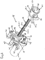
- an annular disk 39 On the hollow shaft 38 is an annular disk 39, which is designed as a toothed belt wheel 40 with teeth 41 on the circumference.
- the hollow shaft 38 projects from the annular disk 39 on both sides.
- the external thread 31 of the threaded spindle 28 and the internal thread 35 of the spindle nut 29 are matched to one another, so that the threaded spindle 28 can be screwed into the spindle nut 29.
- the metering drive 26 according to FIG Fig. 3 an electric drive motor 42 which carries a further toothed belt wheel 44 on a motor shaft 43.
- the spindle nut 29 is rotatably mounted on the hollow shaft 38 in two bearing bushes 45 which are held in two parallel holding plates 46 of a holder 47 at a defined distance from one another and from the drive motor 42.
- the holder 47 has bearing eyes 48 for fixing in the housing 2.
- the electronic manual dosing device 1 is an electronic pipette. It has a housing upper part 53 in the form of a handle and an essentially cylindrical housing lower part 54.
- the housing upper part 53 contains a drive unit and the housing lower part 54 contains a displacement unit consisting of a cylinder 55 and a piston 56 which is displaceable therein and which can be displaced by means of the drive unit.
- the head section 58 At the level of the display 6 there are electrical contacts 9, 10 on the left and right side of the head section 58 for charging an accumulator of an electrical power supply 11 accommodated in the head section 58.
- the accumulator is connected to an electrical control device 52 accommodated in the head section 58.
- the electrical control device 52 is connected to the rocker button 59 and the further buttons 60, a sensor for detecting the rotational position of the selection wheel 5 and a drive motor 42 of a metering drive 26.
- An ejector sleeve 72 adapted to the outer shape thereof, for pushing off the pipette tip 61 from the sealing seat 69 is pushed onto the cylinder section 66, the connecting section 67 and the tube 68.
- the ejector sleeve 73 is connected to the ejector rod via detachable coupling means of the ejector sleeve 73 and the ejector rod.
- the releasable coupling means consist in a press fit of the lower end of the ejector rod in a bore in a lateral projection on the upper edge of the ejector sleeve 73.
- the piston 56 is connected to a piston rod 78 which carries a plate 79 at the top. Between the plate 79 and the upper edge of the cylinder 55, a helical spring 80 is arranged, which presses the plate 79 into an initial position on the underside of the cap base 76.
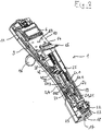
- the metering drive 26 largely corresponds to the metering drive 26 of FIG Fig. 3 , so the comments too Fig. 3 correspondingly for the features of the same reference numerals of 12 and 13 be valid.
- the lower end of the threaded spindle 28 contacts the plate 79 and is not connected to a bell-shaped receiving body 19.
- guide elements 50.1, 50.2 on the receiving body 19 Rather, the threaded spindle 28 is guided at the upper end in a guide cylinder 81 which protrudes from the upper side of the holder 47 for the bearing bushes 45 of the spindle nut 29.
- the threaded spindle 28 is connected to a measuring sleeve 93 via a slip clutch (not shown) (not shown).
- the upper part of the measuring sleeve 93 is cut away in the drawing for better understanding.
- the Measuring sleeve 93 has a second scale 94 running in the circumferential direction with a division of a hundredth of a millimeter.
Landscapes
- Engineering & Computer Science (AREA)
- General Engineering & Computer Science (AREA)
- Mechanical Engineering (AREA)
- Health & Medical Sciences (AREA)
- Clinical Laboratory Science (AREA)
- Chemical & Material Sciences (AREA)
- Chemical Kinetics & Catalysis (AREA)
- Physics & Mathematics (AREA)
- General Physics & Mathematics (AREA)
- Transmission Devices (AREA)
- Devices For Use In Laboratory Experiments (AREA)
Priority Applications (6)
| Application Number | Priority Date | Filing Date | Title |
|---|---|---|---|
| PL17169766T PL3399215T3 (pl) | 2017-05-05 | 2017-05-05 | Napęd wrzeciona |
| EP17169766.7A EP3399215B1 (de) | 2017-05-05 | 2017-05-05 | Spindelantrieb |
| US16/610,983 US11280389B2 (en) | 2017-05-05 | 2018-05-02 | Spindle drive |
| CN201880042154.3A CN110785584B (zh) | 2017-05-05 | 2018-05-02 | 主轴驱动装置 |
| JP2019559773A JP6965369B2 (ja) | 2017-05-05 | 2018-05-02 | スピンドル装置 |
| PCT/EP2018/061222 WO2018202725A1 (de) | 2017-05-05 | 2018-05-02 | Spindelantrieb |
Applications Claiming Priority (1)
| Application Number | Priority Date | Filing Date | Title |
|---|---|---|---|
| EP17169766.7A EP3399215B1 (de) | 2017-05-05 | 2017-05-05 | Spindelantrieb |
Publications (2)
| Publication Number | Publication Date |
|---|---|
| EP3399215A1 EP3399215A1 (de) | 2018-11-07 |
| EP3399215B1 true EP3399215B1 (de) | 2020-07-08 |
Family
ID=58671539
Family Applications (1)
| Application Number | Title | Priority Date | Filing Date |
|---|---|---|---|
| EP17169766.7A Active EP3399215B1 (de) | 2017-05-05 | 2017-05-05 | Spindelantrieb |
Country Status (6)
| Country | Link |
|---|---|
| US (1) | US11280389B2 (pl) |
| EP (1) | EP3399215B1 (pl) |
| JP (1) | JP6965369B2 (pl) |
| CN (1) | CN110785584B (pl) |
| PL (1) | PL3399215T3 (pl) |
| WO (1) | WO2018202725A1 (pl) |
Families Citing this family (6)
| Publication number | Priority date | Publication date | Assignee | Title |
|---|---|---|---|---|
| US11781624B2 (en) * | 2019-09-23 | 2023-10-10 | D-Box Technologies Inc. | Linear actuator for motion simulator |
| DE102020202196A1 (de) * | 2020-02-20 | 2021-08-26 | Thyssenkrupp Ag | Verstellantrieb für eine Lenksäule und Lenksäule für ein Kraftfahrzeug |
| JP7315625B2 (ja) * | 2020-07-14 | 2023-07-26 | エッペンドルフ エスイー | 一体型プランジャを備えたピペット・チップとともに使用するためのピペット |
| EP4134166A1 (de) | 2021-08-09 | 2023-02-15 | Eppendorf SE | Pipette für den gebrauch mit einer pipettenspitze |
| DE102022105754A1 (de) | 2022-03-11 | 2023-09-14 | Brand Gmbh + Co Kg | Pipettiervorrichtung |
| DE102022105753B3 (de) | 2022-03-11 | 2023-07-06 | Brand Gmbh + Co Kg | Pipettiervorrichtung |
Family Cites Families (20)
| Publication number | Priority date | Publication date | Assignee | Title |
|---|---|---|---|---|
| DE1053883B (de) | 1957-06-03 | 1959-03-26 | Strobach Doerge & Co O H G | Gewindespindel |
| JPS5322853B2 (pl) * | 1972-07-11 | 1978-07-11 | ||
| US4098125A (en) * | 1977-03-30 | 1978-07-04 | Lee Thomas E | Adjustable volume pipetting device |
| JPS6334361A (ja) * | 1986-07-25 | 1988-02-15 | Sansui Electric Co | ねじ送り装置 |
| AU3156493A (en) * | 1991-11-29 | 1993-06-28 | Novo Nordisk A/S | A pen-shaped syringe |
| DE4341229C2 (de) | 1993-12-03 | 1995-09-07 | Eppendorf Geraetebau Netheler | Pipettensystem |
| JPH08233831A (ja) * | 1995-02-28 | 1996-09-13 | Suzuki Motor Corp | 電動ピペット保持選択装置 |
| JP4226249B2 (ja) * | 2002-02-13 | 2009-02-18 | Ntn株式会社 | 樹脂製ナットおよびすべりねじ装置 |
| DE10307030A1 (de) | 2003-02-20 | 2004-09-09 | Eppendorf Ag | Dosiersystem |
| WO2007029716A1 (ja) * | 2005-09-05 | 2007-03-15 | Nsk Ltd. | ボールねじ機構及びボールねじの組立方法 |
| GB0524604D0 (en) * | 2005-12-02 | 2006-01-11 | Owen Mumford Ltd | Injection method and apparatus |
| DE102007008053A1 (de) * | 2007-02-15 | 2008-08-21 | Piras Metalltechnik Gmbh & Co. Kg | Vorrichtung zur Erzeugung einer Linearbewegung |
| JP2010043698A (ja) * | 2008-08-12 | 2010-02-25 | Ntn Corp | 樹脂製ナットおよびすべりねじ装置 |
| DE102008048252A1 (de) * | 2008-09-12 | 2010-04-15 | Eppendorf Ag | Pipettiervorrichtung |
| SE535983C2 (sv) * | 2010-04-20 | 2013-03-19 | Noviscens Ab | Spruta |
| DE102011106079B4 (de) * | 2011-06-30 | 2020-06-10 | Robert Bosch Gmbh | Planetengewindetrieb mit Enddichtung mit einzelner Dichtkante |
| EP2854909B1 (en) * | 2012-05-30 | 2020-07-15 | Sanofi-Aventis Deutschland GmbH | Bearing for a piston rod body for a drug delivery device, a piston rod arrangement and a piston rod body |
| DE102015212448B4 (de) * | 2015-07-02 | 2020-07-02 | Zf Friedrichshafen Ag | Spindelantrieb und Aktuator mit einem Spindelantrieb |
| CN205479207U (zh) * | 2016-01-19 | 2016-08-17 | 温州万兆汽车零部件有限公司 | 凹槽传动螺杆 |
| DE102016101629B4 (de) * | 2016-01-29 | 2017-08-24 | HARTING Electronics GmbH | Linearbewegliches Gleitkontaktelement mit Transportvorrichtung und Verfahren zur Herstellung |
-
2017
- 2017-05-05 PL PL17169766T patent/PL3399215T3/pl unknown
- 2017-05-05 EP EP17169766.7A patent/EP3399215B1/de active Active
-
2018
- 2018-05-02 US US16/610,983 patent/US11280389B2/en active Active
- 2018-05-02 WO PCT/EP2018/061222 patent/WO2018202725A1/de not_active Ceased
- 2018-05-02 CN CN201880042154.3A patent/CN110785584B/zh active Active
- 2018-05-02 JP JP2019559773A patent/JP6965369B2/ja active Active
Non-Patent Citations (1)
| Title |
|---|
| None * |
Also Published As
| Publication number | Publication date |
|---|---|
| CN110785584A (zh) | 2020-02-11 |
| PL3399215T3 (pl) | 2021-01-25 |
| CN110785584B (zh) | 2023-04-11 |
| WO2018202725A1 (de) | 2018-11-08 |
| JP2020519817A (ja) | 2020-07-02 |
| US20200072329A1 (en) | 2020-03-05 |
| JP6965369B2 (ja) | 2021-11-10 |
| EP3399215A1 (de) | 2018-11-07 |
| US11280389B2 (en) | 2022-03-22 |
Similar Documents
| Publication | Publication Date | Title |
|---|---|---|
| EP3399214B1 (de) | Elektronischer dosierantrieb | |
| EP3399215B1 (de) | Spindelantrieb | |
| EP2165765B1 (de) | Pipettiervorrichtung mit Doppelgewinde | |
| EP2633915B1 (de) | Pipette mit kalibrierungssystem | |
| EP2024090B1 (de) | Vorrichtung zur halterung von pipettenspitzen, pipettenspitze sowie pipettiervorrichtung | |
| EP3478418A1 (de) | Dosierkopf, dosiervorrichtung umfassend einen dosierkopf und verfahren zum dosieren mittels eines dosierkopfes | |
| EP3164214B1 (de) | Pipette zum betätigen einer spritze | |
| EP2659978B1 (de) | Pipette mit Verriegelungssystem | |
| EP1743701B1 (de) | Kolbenhubpipette | |
| WO2016023794A1 (de) | Mehrfachwerkzeug | |
| DE102015116559A1 (de) | Werkzeugwechsel bei Blindnietmuttern | |
| EP2783753B1 (de) | Dispenser zum betätigen einer spritze | |
| EP3554709B1 (de) | Dispenser, system und verfahren zum aufnehmen und abgeben von fluidvolumina | |
| EP4134166A1 (de) | Pipette für den gebrauch mit einer pipettenspitze | |
| DE20006547U1 (de) | Verstellvorrichtung | |
| EP3915682B1 (de) | Pipette mit einstellbarem dosiervolumen | |
| EP4647230A1 (de) | Getriebevorrichtung, formgebungswerkzeug und formgebungsvorrichtung | |
| EP4331725A1 (de) | Kolbenstange und verfahren zur herstellung einer solchen kolbenstange | |
| WO2025099117A1 (de) | Mehrkanal-unterteil für eine fluidübertragungsvorrichtung sowie mehrkanal-fluidübertragungsvorrichtung | |
| DE102017103744A1 (de) | Dispenser, System und Verfahren zum Aufnehmen und Abgeben von Fluidvolumina |
Legal Events
| Date | Code | Title | Description |
|---|---|---|---|
| PUAI | Public reference made under article 153(3) epc to a published international application that has entered the european phase |
Free format text: ORIGINAL CODE: 0009012 |
|
| STAA | Information on the status of an ep patent application or granted ep patent |
Free format text: STATUS: THE APPLICATION HAS BEEN PUBLISHED |
|
| AK | Designated contracting states |
Kind code of ref document: A1 Designated state(s): AL AT BE BG CH CY CZ DE DK EE ES FI FR GB GR HR HU IE IS IT LI LT LU LV MC MK MT NL NO PL PT RO RS SE SI SK SM TR |
|
| AX | Request for extension of the european patent |
Extension state: BA ME |
|
| STAA | Information on the status of an ep patent application or granted ep patent |
Free format text: STATUS: REQUEST FOR EXAMINATION WAS MADE |
|
| 17P | Request for examination filed |
Effective date: 20190502 |
|
| RBV | Designated contracting states (corrected) |
Designated state(s): AL AT BE BG CH CY CZ DE DK EE ES FI FR GB GR HR HU IE IS IT LI LT LU LV MC MK MT NL NO PL PT RO RS SE SI SK SM TR |
|
| RIC1 | Information provided on ipc code assigned before grant |
Ipc: B01L 3/02 20060101ALN20200115BHEP Ipc: F16H 25/24 20060101AFI20200115BHEP Ipc: G01B 3/18 20060101ALN20200115BHEP Ipc: G01N 35/10 20060101ALN20200115BHEP |
|
| GRAP | Despatch of communication of intention to grant a patent |
Free format text: ORIGINAL CODE: EPIDOSNIGR1 |
|
| STAA | Information on the status of an ep patent application or granted ep patent |
Free format text: STATUS: GRANT OF PATENT IS INTENDED |
|
| INTG | Intention to grant announced |
Effective date: 20200221 |
|
| GRAS | Grant fee paid |
Free format text: ORIGINAL CODE: EPIDOSNIGR3 |
|
| GRAA | (expected) grant |
Free format text: ORIGINAL CODE: 0009210 |
|
| STAA | Information on the status of an ep patent application or granted ep patent |
Free format text: STATUS: THE PATENT HAS BEEN GRANTED |
|
| AK | Designated contracting states |
Kind code of ref document: B1 Designated state(s): AL AT BE BG CH CY CZ DE DK EE ES FI FR GB GR HR HU IE IS IT LI LT LU LV MC MK MT NL NO PL PT RO RS SE SI SK SM TR |
|
| RIN1 | Information on inventor provided before grant (corrected) |
Inventor name: REICHMUTH, BURKHARDT Inventor name: WILTH, MARC Inventor name: SATTLER, JOERG |
|
| REG | Reference to a national code |
Ref country code: CH Ref legal event code: EP Ref country code: AT Ref legal event code: REF Ref document number: 1288802 Country of ref document: AT Kind code of ref document: T Effective date: 20200715 |
|
| REG | Reference to a national code |
Ref country code: DE Ref legal event code: R096 Ref document number: 502017006043 Country of ref document: DE |
|
| REG | Reference to a national code |
Ref country code: IE Ref legal event code: FG4D Free format text: LANGUAGE OF EP DOCUMENT: GERMAN |
|
| REG | Reference to a national code |
Ref country code: FI Ref legal event code: FGE |
|
| REG | Reference to a national code |
Ref country code: DE Ref legal event code: R082 Ref document number: 502017006043 Country of ref document: DE |
|
| REG | Reference to a national code |
Ref country code: LT Ref legal event code: MG4D |
|
| REG | Reference to a national code |
Ref country code: CH Ref legal event code: NV Representative=s name: BOHEST AG, CH |
|
| REG | Reference to a national code |
Ref country code: NL Ref legal event code: MP Effective date: 20200708 |
|
| PG25 | Lapsed in a contracting state [announced via postgrant information from national office to epo] |
Ref country code: SE Free format text: LAPSE BECAUSE OF FAILURE TO SUBMIT A TRANSLATION OF THE DESCRIPTION OR TO PAY THE FEE WITHIN THE PRESCRIBED TIME-LIMIT Effective date: 20200708 Ref country code: BG Free format text: LAPSE BECAUSE OF FAILURE TO SUBMIT A TRANSLATION OF THE DESCRIPTION OR TO PAY THE FEE WITHIN THE PRESCRIBED TIME-LIMIT Effective date: 20201008 Ref country code: HR Free format text: LAPSE BECAUSE OF FAILURE TO SUBMIT A TRANSLATION OF THE DESCRIPTION OR TO PAY THE FEE WITHIN THE PRESCRIBED TIME-LIMIT Effective date: 20200708 Ref country code: ES Free format text: LAPSE BECAUSE OF FAILURE TO SUBMIT A TRANSLATION OF THE DESCRIPTION OR TO PAY THE FEE WITHIN THE PRESCRIBED TIME-LIMIT Effective date: 20200708 Ref country code: LT Free format text: LAPSE BECAUSE OF FAILURE TO SUBMIT A TRANSLATION OF THE DESCRIPTION OR TO PAY THE FEE WITHIN THE PRESCRIBED TIME-LIMIT Effective date: 20200708 Ref country code: PT Free format text: LAPSE BECAUSE OF FAILURE TO SUBMIT A TRANSLATION OF THE DESCRIPTION OR TO PAY THE FEE WITHIN THE PRESCRIBED TIME-LIMIT Effective date: 20201109 Ref country code: GR Free format text: LAPSE BECAUSE OF FAILURE TO SUBMIT A TRANSLATION OF THE DESCRIPTION OR TO PAY THE FEE WITHIN THE PRESCRIBED TIME-LIMIT Effective date: 20201009 Ref country code: NO Free format text: LAPSE BECAUSE OF FAILURE TO SUBMIT A TRANSLATION OF THE DESCRIPTION OR TO PAY THE FEE WITHIN THE PRESCRIBED TIME-LIMIT Effective date: 20201008 |
|
| PG25 | Lapsed in a contracting state [announced via postgrant information from national office to epo] |
Ref country code: RS Free format text: LAPSE BECAUSE OF FAILURE TO SUBMIT A TRANSLATION OF THE DESCRIPTION OR TO PAY THE FEE WITHIN THE PRESCRIBED TIME-LIMIT Effective date: 20200708 Ref country code: LV Free format text: LAPSE BECAUSE OF FAILURE TO SUBMIT A TRANSLATION OF THE DESCRIPTION OR TO PAY THE FEE WITHIN THE PRESCRIBED TIME-LIMIT Effective date: 20200708 Ref country code: IS Free format text: LAPSE BECAUSE OF FAILURE TO SUBMIT A TRANSLATION OF THE DESCRIPTION OR TO PAY THE FEE WITHIN THE PRESCRIBED TIME-LIMIT Effective date: 20201108 |
|
| PG25 | Lapsed in a contracting state [announced via postgrant information from national office to epo] |
Ref country code: NL Free format text: LAPSE BECAUSE OF FAILURE TO SUBMIT A TRANSLATION OF THE DESCRIPTION OR TO PAY THE FEE WITHIN THE PRESCRIBED TIME-LIMIT Effective date: 20200708 |
|
| REG | Reference to a national code |
Ref country code: DE Ref legal event code: R097 Ref document number: 502017006043 Country of ref document: DE |
|
| PG25 | Lapsed in a contracting state [announced via postgrant information from national office to epo] |
Ref country code: DK Free format text: LAPSE BECAUSE OF FAILURE TO SUBMIT A TRANSLATION OF THE DESCRIPTION OR TO PAY THE FEE WITHIN THE PRESCRIBED TIME-LIMIT Effective date: 20200708 Ref country code: CZ Free format text: LAPSE BECAUSE OF FAILURE TO SUBMIT A TRANSLATION OF THE DESCRIPTION OR TO PAY THE FEE WITHIN THE PRESCRIBED TIME-LIMIT Effective date: 20200708 Ref country code: RO Free format text: LAPSE BECAUSE OF FAILURE TO SUBMIT A TRANSLATION OF THE DESCRIPTION OR TO PAY THE FEE WITHIN THE PRESCRIBED TIME-LIMIT Effective date: 20200708 Ref country code: SM Free format text: LAPSE BECAUSE OF FAILURE TO SUBMIT A TRANSLATION OF THE DESCRIPTION OR TO PAY THE FEE WITHIN THE PRESCRIBED TIME-LIMIT Effective date: 20200708 Ref country code: IT Free format text: LAPSE BECAUSE OF FAILURE TO SUBMIT A TRANSLATION OF THE DESCRIPTION OR TO PAY THE FEE WITHIN THE PRESCRIBED TIME-LIMIT Effective date: 20200708 Ref country code: EE Free format text: LAPSE BECAUSE OF FAILURE TO SUBMIT A TRANSLATION OF THE DESCRIPTION OR TO PAY THE FEE WITHIN THE PRESCRIBED TIME-LIMIT Effective date: 20200708 |
|
| PLBE | No opposition filed within time limit |
Free format text: ORIGINAL CODE: 0009261 |
|
| STAA | Information on the status of an ep patent application or granted ep patent |
Free format text: STATUS: NO OPPOSITION FILED WITHIN TIME LIMIT |
|
| PG25 | Lapsed in a contracting state [announced via postgrant information from national office to epo] |
Ref country code: AL Free format text: LAPSE BECAUSE OF FAILURE TO SUBMIT A TRANSLATION OF THE DESCRIPTION OR TO PAY THE FEE WITHIN THE PRESCRIBED TIME-LIMIT Effective date: 20200708 |
|
| 26N | No opposition filed |
Effective date: 20210409 |
|
| PG25 | Lapsed in a contracting state [announced via postgrant information from national office to epo] |
Ref country code: SK Free format text: LAPSE BECAUSE OF FAILURE TO SUBMIT A TRANSLATION OF THE DESCRIPTION OR TO PAY THE FEE WITHIN THE PRESCRIBED TIME-LIMIT Effective date: 20200708 |
|
| PG25 | Lapsed in a contracting state [announced via postgrant information from national office to epo] |
Ref country code: SI Free format text: LAPSE BECAUSE OF FAILURE TO SUBMIT A TRANSLATION OF THE DESCRIPTION OR TO PAY THE FEE WITHIN THE PRESCRIBED TIME-LIMIT Effective date: 20200708 |
|
| PG25 | Lapsed in a contracting state [announced via postgrant information from national office to epo] |
Ref country code: LU Free format text: LAPSE BECAUSE OF NON-PAYMENT OF DUE FEES Effective date: 20210505 Ref country code: MC Free format text: LAPSE BECAUSE OF FAILURE TO SUBMIT A TRANSLATION OF THE DESCRIPTION OR TO PAY THE FEE WITHIN THE PRESCRIBED TIME-LIMIT Effective date: 20200708 |
|
| REG | Reference to a national code |
Ref country code: BE Ref legal event code: MM Effective date: 20210531 |
|
| PG25 | Lapsed in a contracting state [announced via postgrant information from national office to epo] |
Ref country code: IE Free format text: LAPSE BECAUSE OF NON-PAYMENT OF DUE FEES Effective date: 20210505 |
|
| PG25 | Lapsed in a contracting state [announced via postgrant information from national office to epo] |
Ref country code: BE Free format text: LAPSE BECAUSE OF NON-PAYMENT OF DUE FEES Effective date: 20210531 |
|
| REG | Reference to a national code |
Ref country code: DE Ref legal event code: R081 Ref document number: 502017006043 Country of ref document: DE Owner name: EPPENDORF SE, DE Free format text: FORMER OWNER: EPPENDORF AG, 22339 HAMBURG, DE |
|
| PG25 | Lapsed in a contracting state [announced via postgrant information from national office to epo] |
Ref country code: CY Free format text: LAPSE BECAUSE OF FAILURE TO SUBMIT A TRANSLATION OF THE DESCRIPTION OR TO PAY THE FEE WITHIN THE PRESCRIBED TIME-LIMIT Effective date: 20200708 |
|
| P01 | Opt-out of the competence of the unified patent court (upc) registered |
Effective date: 20230527 |
|
| REG | Reference to a national code |
Ref country code: AT Ref legal event code: MM01 Ref document number: 1288802 Country of ref document: AT Kind code of ref document: T Effective date: 20220505 |
|
| PG25 | Lapsed in a contracting state [announced via postgrant information from national office to epo] |
Ref country code: HU Free format text: LAPSE BECAUSE OF FAILURE TO SUBMIT A TRANSLATION OF THE DESCRIPTION OR TO PAY THE FEE WITHIN THE PRESCRIBED TIME-LIMIT; INVALID AB INITIO Effective date: 20170505 Ref country code: AT Free format text: LAPSE BECAUSE OF NON-PAYMENT OF DUE FEES Effective date: 20220505 |
|
| PG25 | Lapsed in a contracting state [announced via postgrant information from national office to epo] |
Ref country code: MK Free format text: LAPSE BECAUSE OF FAILURE TO SUBMIT A TRANSLATION OF THE DESCRIPTION OR TO PAY THE FEE WITHIN THE PRESCRIBED TIME-LIMIT Effective date: 20200708 |
|
| PG25 | Lapsed in a contracting state [announced via postgrant information from national office to epo] |
Ref country code: MT Free format text: LAPSE BECAUSE OF FAILURE TO SUBMIT A TRANSLATION OF THE DESCRIPTION OR TO PAY THE FEE WITHIN THE PRESCRIBED TIME-LIMIT Effective date: 20200708 |
|
| PGFP | Annual fee paid to national office [announced via postgrant information from national office to epo] |
Ref country code: FI Payment date: 20250526 Year of fee payment: 9 |
|
| PGFP | Annual fee paid to national office [announced via postgrant information from national office to epo] |
Ref country code: PL Payment date: 20250425 Year of fee payment: 9 Ref country code: DE Payment date: 20250521 Year of fee payment: 9 |
|
| PGFP | Annual fee paid to national office [announced via postgrant information from national office to epo] |
Ref country code: GB Payment date: 20250527 Year of fee payment: 9 |
|
| PGFP | Annual fee paid to national office [announced via postgrant information from national office to epo] |
Ref country code: FR Payment date: 20250528 Year of fee payment: 9 |
|
| PGFP | Annual fee paid to national office [announced via postgrant information from national office to epo] |
Ref country code: CH Payment date: 20250601 Year of fee payment: 9 |
|
| PG25 | Lapsed in a contracting state [announced via postgrant information from national office to epo] |
Ref country code: TR Free format text: LAPSE BECAUSE OF FAILURE TO SUBMIT A TRANSLATION OF THE DESCRIPTION OR TO PAY THE FEE WITHIN THE PRESCRIBED TIME-LIMIT Effective date: 20200708 |