EP3399248B1 - Unité intérieure de climatiseur - Google Patents
Unité intérieure de climatiseur Download PDFInfo
- Publication number
- EP3399248B1 EP3399248B1 EP18178346.5A EP18178346A EP3399248B1 EP 3399248 B1 EP3399248 B1 EP 3399248B1 EP 18178346 A EP18178346 A EP 18178346A EP 3399248 B1 EP3399248 B1 EP 3399248B1
- Authority
- EP
- European Patent Office
- Prior art keywords
- flow fan
- diagonal flow
- indoor unit
- air
- unit
- Prior art date
- Legal status (The legal status is an assumption and is not a legal conclusion. Google has not performed a legal analysis and makes no representation as to the accuracy of the status listed.)
- Active
Links
Images






Classifications
-
- F—MECHANICAL ENGINEERING; LIGHTING; HEATING; WEAPONS; BLASTING
- F24—HEATING; RANGES; VENTILATING
- F24F—AIR-CONDITIONING; AIR-HUMIDIFICATION; VENTILATION; USE OF AIR CURRENTS FOR SCREENING
- F24F7/00—Ventilation
- F24F7/007—Ventilation with forced flow
-
- F—MECHANICAL ENGINEERING; LIGHTING; HEATING; WEAPONS; BLASTING
- F24—HEATING; RANGES; VENTILATING
- F24F—AIR-CONDITIONING; AIR-HUMIDIFICATION; VENTILATION; USE OF AIR CURRENTS FOR SCREENING
- F24F1/00—Room units for air-conditioning, e.g. separate or self-contained units or units receiving primary air from a central station
- F24F1/0007—Indoor units, e.g. fan coil units
- F24F1/0011—Indoor units, e.g. fan coil units characterised by air outlets
-
- F—MECHANICAL ENGINEERING; LIGHTING; HEATING; WEAPONS; BLASTING
- F24—HEATING; RANGES; VENTILATING
- F24F—AIR-CONDITIONING; AIR-HUMIDIFICATION; VENTILATION; USE OF AIR CURRENTS FOR SCREENING
- F24F1/00—Room units for air-conditioning, e.g. separate or self-contained units or units receiving primary air from a central station
- F24F1/0007—Indoor units, e.g. fan coil units
- F24F1/0018—Indoor units, e.g. fan coil units characterised by fans
- F24F1/0022—Centrifugal or radial fans
-
- F—MECHANICAL ENGINEERING; LIGHTING; HEATING; WEAPONS; BLASTING
- F24—HEATING; RANGES; VENTILATING
- F24F—AIR-CONDITIONING; AIR-HUMIDIFICATION; VENTILATION; USE OF AIR CURRENTS FOR SCREENING
- F24F1/00—Room units for air-conditioning, e.g. separate or self-contained units or units receiving primary air from a central station
- F24F1/0007—Indoor units, e.g. fan coil units
- F24F1/0043—Indoor units, e.g. fan coil units characterised by mounting arrangements
- F24F1/005—Indoor units, e.g. fan coil units characterised by mounting arrangements mounted on the floor; standing on the floor
-
- F—MECHANICAL ENGINEERING; LIGHTING; HEATING; WEAPONS; BLASTING
- F24—HEATING; RANGES; VENTILATING
- F24F—AIR-CONDITIONING; AIR-HUMIDIFICATION; VENTILATION; USE OF AIR CURRENTS FOR SCREENING
- F24F1/00—Room units for air-conditioning, e.g. separate or self-contained units or units receiving primary air from a central station
- F24F1/0007—Indoor units, e.g. fan coil units
- F24F1/0018—Indoor units, e.g. fan coil units characterised by fans
- F24F1/0025—Cross-flow or tangential fans
-
- F—MECHANICAL ENGINEERING; LIGHTING; HEATING; WEAPONS; BLASTING
- F24—HEATING; RANGES; VENTILATING
- F24F—AIR-CONDITIONING; AIR-HUMIDIFICATION; VENTILATION; USE OF AIR CURRENTS FOR SCREENING
- F24F1/00—Room units for air-conditioning, e.g. separate or self-contained units or units receiving primary air from a central station
- F24F1/0007—Indoor units, e.g. fan coil units
- F24F1/0018—Indoor units, e.g. fan coil units characterised by fans
- F24F1/0033—Indoor units, e.g. fan coil units characterised by fans having two or more fans
-
- Y—GENERAL TAGGING OF NEW TECHNOLOGICAL DEVELOPMENTS; GENERAL TAGGING OF CROSS-SECTIONAL TECHNOLOGIES SPANNING OVER SEVERAL SECTIONS OF THE IPC; TECHNICAL SUBJECTS COVERED BY FORMER USPC CROSS-REFERENCE ART COLLECTIONS [XRACs] AND DIGESTS
- Y02—TECHNOLOGIES OR APPLICATIONS FOR MITIGATION OR ADAPTATION AGAINST CLIMATE CHANGE
- Y02B—CLIMATE CHANGE MITIGATION TECHNOLOGIES RELATED TO BUILDINGS, e.g. HOUSING, HOUSE APPLIANCES OR RELATED END-USER APPLICATIONS
- Y02B30/00—Energy efficient heating, ventilation or air conditioning [HVAC]
- Y02B30/70—Efficient control or regulation technologies, e.g. for control of refrigerant flow, motor or heating
Definitions
- the present invention relates to an indoor unit of an air conditioner having improved structures of suction, discharge and flow passages.
- An air conditioner which generally uses a refrigeration cycle to adjust temperature, humidity, flow and distribution of ambient air to levels proper for human activities and remove dust from the air, includes a compressor, a condenser, an evaporator and a blower fan.
- Air conditioners may be divided into a split type air conditioner, which has an indoor unit and an outdoor unit separately installed, and an integrated type air conditioner, which has an indoor unit and an outdoor unit installed together in a cabinet.
- the indoor unit of the split type air conditioner is provided with a heat exchanger to exchange heat with air suctioned into a panel, and a blower fan to suction the indoor air into the panel and blow the same to the room.
- a blower fan is generally disposed at the lower portion of the indoor unit, and a heat exchanger and an air discharge outlet allowing air to be discharged therethrough are disposed at the upper portion of the indoor unit.
- the air suctioned and blown by the blower fan moves to the upper portion of the indoor unit, passes the heat exchanger and the air discharge outlet, and is then discharged to the room.
- the vertical arrangement of the blower fan and the heat exchanger may not be efficient in view of space utilization.
- EP1467156 , EP1016790 and CN1399102 each disclose an indoor unit of an air conditioner having a fan and a diffuser.
- an indoor unit of an air conditioner as set out in claim 1.
- an aspect of the present invention to provide an indoor unit of an air conditioner provided with improved structures of suction, discharge and air flow passages to increase operational efficiency, lower noise level, and realize a compact size.
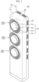
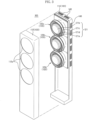
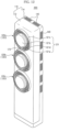
- the indoor unit of air conditioner 100 includes a housing 110 forming an external appearance of the indoor unit 100, a plurality of diagonal flow fan units 120 disposed in the housing 110, at least one heat exchanger 130 disposed at the rear of the diagonal flow fan units 120 in the housing 110 and a plurality of suction inlets 140 provided on the rear surface of the housing 110.
- the housing 110 includes a front panel 112 provided with a plurality of openings 112a allowing the discharge outlet 121a of the diagonal flow fan unit 120 to be exposed at the front side thereof, a rear panel 114 coupled to the rear side of the front panel 112.
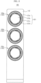
- the openings 112a are formed in a circular shape, and at least two thereof may be disposed spaced apart from each other in a vertical direction of the front panel 112.
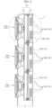
- Each of the diagonal flow fan units 120 includes a diffuser 121 forming a discharge outlet 121a, a drive motor 122 coupled to the rear surface of the diffuser 121, a diagonal flow fan 123 rotatably coupled to the drive motor 122, and a duct 124 coupled to the rear surface of the diffuser 121 to form a flow passage 124a allowing the air suctioned by the diagonal flow fan 123 to move therethrough to be discharged to the discharge outlet 121a.
- the fan provides a suction force for the air to move it to the discharge outlet.
- the diffuser 121 includes a circular disc plate 121b, a circular grille 121c coupled to the outer circumferential surface of the circular disc plate 121b, and a ring-shaped discharge outlet 121a formed between the circular disc plate 121b and the grille 121c.
- the diffuser 121 is disposed at the front side of the diagonal flow fan 123 to allow the air from the diagonal flow fan 123 to be discharged through the discharge outlet 121a to diverge in all directions toward the front of the front panel 112.
- the circular disc plate 121b is disposed at the center of the circular grille 121c.
- the position of the circular disc plate 121b is not limited to the center of the circular grille 121c.
- the diameter of the circular disc plate 121b which is related to noise generated when air is discharged from the indoor unit 100 of an air conditioner, may be between 225mm and 265mm.
- the circular disc plate 121b and the grille 121c may be adapted to move in a direction in which the air is discharged from the indoor unit 100 or the direction opposite thereto.
- the grille 121c includes blade plates 121d, and the flow direction and flow rate of the air discharged through the discharge outlet 121a may be adjusted by changing the number, shape and orientation of the blade plates 121d.
- the flow direction and volume of air discharged through the discharge outlet 121a may also be adjusted by widening or narrowing the radial width of the discharge outlet 121a through adjustment of the distance between the circular disc plate 121b and the grille 121c, or by changing the diameter of the circular disc plate 121b.
- the drive motor 122 is coupled to the rear surface of the circular disc plate 121b with the rotating shaft 122a thereof arranged facing the rear panel 114, and adapted to rotate the diagonal flow fan 123.
- the diagonal flow fan 123 which functions as a fan to blow air introduced into the housing and is disposed between the diffuser 121 and the heat exchanger 130 to suction the air which has exchanged heat in the heat exchanger 130 and discharge the same to the discharge outlet 121a, includes a hub 123a coupled to the rotating shaft 122a of the drive motor 122, and a plurality of blades 123b coupled to the outer circumferential surface of the hub 123a.
- the diameter of the hub 123a gradually decreases in a direction toward the suction inlet 140and toward the rear panel 114, and thereby the outer circumferential surface of the hub 123a is formed inclined.
- an angle ⁇ formed between the lines L1 and L3 extending along the inclined outer circumferential surface of the hub 123a and an imaginary line Lc passing through the center of the rotating shaft 122a of the drive motor 122 may be between about 10° and about 40°.
- the radius of the circular disc plate 121b may be within a range between 0.8R and 1.2R. According to the Coanda effect, the circular disc plate 121b causes the air to flow along the surface thereof.
- the circular disc plate 121b functions to suppress creation of a vortex on the front surface of the discharge outlet 121a due to flow of the air.
- the circular disc plate 121b is within a range between 0.8R and 1.2R, an aesthetically pleasing external appearance may be provided and creation of a vortex on the front surface of the discharge outlet 121a may be suppressed, and thereby the performance of the indoor unit 100 may be increased.
- At least three of the blades 123b are disposed equally spaced apart from each other along the outer circumferential surface of the hub 123a.
- the blades 123b rotate together with the hub 123a, the blades 123b form a pressure gradient from the front side of the diagonal flow fan 123 to the rear side thereof to produce uniform flow of air.
- the arc that connects the opposite lateral edges of the blade 123b is formed by two arcs having different radii of curvature.
- the boundary 129 between the first arc 129a and the second arc 129b may be positioned at a position close to the rear surface of the blade 123b beyond the center of the blade 123b.
- the separation region in which the flow of air along the surface of the blade 123b is separated from the surface of the blade 123b may be narrowed compared to the case of having the boundary 129 between the first arc 129a and the second arc 129b positioned at the center or front surface of the blade 123b. Therefore, performance degradation of the indoor unit 100 due to separation may be prevented and, accordingly, noise level may be lowered.
- the shortest distance d1 may be between about 20mm and about 50mm. If the shortest distance d1 is less than 20mm, the distance between the diagonal flow fan 123 and the heat exchanger 130 may be shortened, resulting in generation of suction resistance and increase of noise during operation. If the shortest distance d1 is greater than 50mm, the distance between the diagonal flow fan 123 and the heat exchanger 130 may be widened, and thereby the air having exchanged heat in the heat exchanger 130 may be not be smoothly suctioned into the diagonal flow fan 123.
- the shortest distance between the heat exchanger 130 and the suction inlet 140 is defined as d2
- the shortest distance d2 may be between about 40mm and about 60mm.
- the duct 124 includes a flow passage forming duct 124a formed in a circular shape to surround the diagonal flow fan 123 and define, in cooperation with the hub 123a, a flow passage for the air suctioned by the diagonal flow fan 123 to flow to the discharge outlet 121a and a fixing plate 124b connected to the rear side of the flow passage forming duct 124a to fix the duct 124 within the housing 110.
- the flow passage forming duct 124a has an inclined lateral surface to allow the air suctioned by the hub 123a and the diagonal flow fan 123 to be slantingly discharged toward the discharge outlet 121a.
- the angle formed between the line L2 extending along the lateral surface of the flow passage forming duct 124 and the line Lp parallel to the imaginary line passing the center of rotation of the diagonal flow fan 123 may be between about 5° and about 15°.
- the diffuser 121 is coupled and fixed to the front surface of the inlet of the flow passage forming duct 124c, and the duct 124 is coupled and fixed to a fixing frame 150 through a fixing plate 124b formed in a rectangular shape.
- the hub 123a and the duct 124 function to guide the introduced air such that the air is discharged to the front through the discharge outlet 121a. Accordingly, the hub 123a and the duct 124 may be viewed respectively as a first guide unit and a second guide unit.
- the heat exchanger 130 is disposed between the diagonal flow fan unit 120 and the suction inlet 140 to absorb heat from the air introduced through the suction inlet 140 or transfer heat to the air introduced through the suction inlet 140.
- the heat exchanger 130 includes a tube 132, and a header 134 attached to the upper and lower side of the tube 132.
- One or more heat exchangers 130 may be disposed in the indoor unit 100. That is, a plurality of the heat exchangers 130 may be provided corresponding to the number of the diagonal flow fan units 120 and disposed respectively at the rear sides of the diagonal flow fan unit 120, or a single heat exchanger 130 corresponding to the entire size of all the diagonal flow fan units 120 may be disposed.
- heat exchange capacity may vary among the heat exchangers 130. That is, one of the heat exchangers 130 having a relatively low heat exchange capacity may be disposed at the rear side of a corresponding one of the diagonal flow fan units 120, while another one of the heat exchangers 130 having a relatively large capacity of heat exchange may be disposed at the rear side of two or more diagonal flow fan units 120.
- the suction inlet 140 is provided on the rear panel 114 disposed at the rear side of the heat exchanger 130 to guide flow of air from outside the indoor unit 100 into the indoor unit 100.
- the suction inlet 140 may be disposed on at least one of the top surface, lateral surfaces and rear surfaces of the rear panel 114.
- one or more suction inlets 140 may be provided on the rear panel 114.
- the suction inlets 140 corresponding in number to the number of the diagonal flow fan units 120 may be provided on the rear panel 114, or a single suction inlet 140 corresponding to the entire size of the diagonal flow fan units 120 may be provided on the rear panel 114.
- the sizes of the suction inlets 140 may be different from each other. That is, one of the suction inlets 140 may be disposed on a corresponding one of the diagonal flow fan units 120, while another one of the suction inlets 140 may be disposed on at least two corresponding ones of the diagonal flow fan units 120.
- the air introduced into the housing 110 through the suction inlets 140 absorbs or loses heat while passing through the heat exchanger 130.
- the air that has exchanged heat while passing the heat exchanger 130 is suctioned by the diagonal flow fan 123 and discharged to the outside of the housing 110 via the duct 124 and the discharge outlet 121a.
- the angle formed by the direction in which the air is suctioned into the diagonal flow fan 123 and the direction in which the air is discharged through the discharge outlet 121a is between about 15° and about 60°.
- the indoor unit 100 may include a plurality of diagonal flow fan units 120, a plurality of the heat exchangers 130 and a plurality of suction inlets 140.
- a description will be given of a case in which the plurality of diagonal flow fan units 120, the plurality of heat exchangers 130, and the plurality of suction inlets 140 are arranged at the upper portion, middle portion and lower portion of the indoor unit 100 in a longitudinal direction of the indoor unit 100 as shown in FIG. 5 .
- the plurality of diagonal flow fan units 120 includes a first diagonal flow fan unit 120a, a second diagonal flow fan unit 120b and a third diagonal flow fan unit 120c which are disposed spaced apart from each other in the longitudinal direction of the indoor unit 100.
- the plurality of heat exchangers 130 includes a first heat exchanger 130a, a second heat exchanger 130b and a third heat exchanger 130c which are disposed spaced apart from each other between the diagonal flow fan units 120 and the suction inlets 140 in the longitudinal direction of the indoor unit 100.
- the plurality of suction inlets 140 includes a first suction inlet 140a, a second suction inlet 140b and a third suction inlet 140c disposed at the rear side of the heat exchangers 130 spaced apart from each other in the longitudinal direction of the indoor unit 100.
- the first diagonal flow fan unit 120a, the first heat exchanger 130a and the first suction inlet 140a are arranged in a row.
- the second diagonal flow fan unit 120b, the second heat exchanger 130b and the second suction inlet 140b are arranged in a row under the first diagonal flow fan unit 120a, the first heat exchanger 130a and the first suction inlet 140a.
- the third diagonal flow fan unit 120c, the third heat exchanger 130c and the third suction inlet 140c are arranged in a row under the second diagonal flow fan unit 120b, the second heat exchanger 130b and the second suction inlet 140b.
- the indoor unit 100 may have a slim width.
- the operational efficiency of the indoor unit 100 may be increased, while the noise level is lowered.
- the first diagonal flow fan unit 120a, the second diagonal flow fan unit 120b and the third diagonal flow fan unit 120c may be independently turned on/off and controlled to rotate at different speeds.
- the first heat exchanger 130a, the second heat exchanger 130b and the third heat exchanger 130c corresponding respectively to the first diagonal flow fan unit 120a, the second diagonal flow fan unit 120b and the third diagonal flow fan unit 120c may be independently controlled such that a refrigerant is supplied thereto depending on the operational state (ON/OFF) of the first diagonal flow fan unit 120a, the second diagonal flow fan unit 120b and the third diagonal flow fan unit 120c.
- the refrigerant may be controlled to be supplied to the first heat exchanger 130a and the second heat exchanger 130b corresponding to the first diagonal flow fan unit 120a and the second diagonal flow fan unit 120b but not to be supplied to the third heat exchanger 130c corresponding to the third diagonal flow fan unit 120c.
- supply of refrigerant to the first heat exchanger 130a may be controlled by installing valves to shut off the flow passages between refrigerant pipes respectively connected to the first heat exchanger 130a, the second heat exchanger 130b and third heat exchanger 130c and each of the third heat exchanger 130c, the second heat exchanger 130b and the third heat exchanger 130c or by installing a single valve (e.g., a 3-way valve) having a plurality of ports connected to the first heat exchanger 130a, the second heat exchanger 130b and third heat exchanger 130c.
- a single valve e.g., a 3-way valve
- a pneumatic valve and an electronic valve using a solenoid may be used.
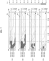
- FIG. 7 is a view illustrating the temperature distribution of air discharged from the discharge outlet in respective operation modes of the indoor unit of the air conditioner according to the illustrated embodiment of the present invention
- FIG. 8 is a view illustrating a control system of the air conditioner according to the illustrated embodiment of the present invention
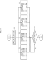
- FIG. 9 is a view illustrating a method of controlling the air conditioner according to the illustrated embodiment of the present invention, based on FIG. 7 .
- FIG. 7 shows the temperature distribution of the air discharged from the discharge outlet 121a in respective operation modes of the indoor unit 100 of the air conditioner according to the illustrated embodiment of the present invention.
- the indoor unit 100 is provided with a plurality of diagonal flow fan units 120a, 120b and 120c which are arranged in a vertical direction (or a longitudinal direction of the indoor unit 100) and perform a desired air conditioning operation by adjusting the flow rate and speed of the air discharged from the diagonal flow fan units 120a, 120b and 120c.
- the adjustment of the flow rate and speed of the air discharged from the diagonal flow fan units 120a, 120b and 120c is implemented by independently turning on/off the diagonal flow fan units 120a, 120b and 120c and independently controlling the rate of rotation (RPM) of each of the diagonal flow fan units 120a, 120b and 120c.
- RPM rate of rotation
- reference numeral 702 represents the bottom surface of the air conditioning space.
- Reference numeral 704 represents the ceiling of the air conditioning space, which is about 250 cm above the bottom surface 702.
- Reference numeral 706 represents a breathing line at a level (e.g. about 165 cm) at which the nose and eyes of an adult of average height (e.g., about 180cm) are arranged.
- the refrigerant may be controlled to be supplied to all of the first heat exchanger 130a, the second heat exchanger 130b and the third heat exchanger 130c respectively corresponding to the first diagonal flow fan unit 120a, the second diagonal flow fan unit 120b and the third diagonal flow fan unit 120c.
- the first diagonal flow fan unit 120a, the second diagonal flow fan unit 120b and the third diagonal flow fan unit 120c are all operated (turned on), a large amount air is discharged and transferred to a far distance, and thus this operation is suitable for air conditioning of a wide area.
- FIG. 7(B) shows a second operation mode, in which the first diagonal flow fan unit 120a, the second diagonal flow fan unit 120b and the third diagonal flow fan unit 120c are all operated (turned on), and the rates of rotation of the first diagonal flow fan unit 120a, the second diagonal flow fan unit 120b and the third diagonal flow fan unit 120c are controlled differently from each other.
- the rates of rotation of the first diagonal flow fan unit 120a and the second diagonal flow fan unit 120b are lower than in the mode of FIG. 7(A) . That is, the rate of rotation of the first diagonal flow fan unit 120a is 600 RPM, the rate of rotation of the second diagonal flow fan unit 120b is 1000 RPM, and the rate of rotation of the third diagonal flow fan unit 120c is 1400 RPM.
- the refrigerant may be controlled to be supplied to all of the first heat exchanger 130a, the second heat exchanger 130b and the third heat exchanger 130c respectively corresponding to the first diagonal flow fan unit 120a, the second diagonal flow fan unit 120b and the third diagonal flow fan unit 120c, as in the first mode.
- the air conditioning effect reaches a distance similar to that in FIG. 7(A) , but the air conditioning is usually implemented below the breathing line 802.
- the rates of rotation of the first diagonal flow fan unit 120a and the second diagonal flow fan unit 120b are relatively low compared to the case of FIG. 7(A) , and thus quiet operation may be possible and energy consumption may be reduced even though the height the effect of air conditioning reaches is relatively low compared to the case shown in FIG. 7(A) .
- FIG. 7(C) shows a third operation mode, in which the first diagonal flow fan unit 120a is at rest (turned off), the second diagonal flow fan unit 120b and the third diagonal flow fan unit 120c are operated (turned on), and the rates of rotation of the second diagonal flow fan unit 120b and the third diagonal flow fan unit 120c are different from each other. That is, the first diagonal flow fan unit 120a is maintained at rest, the rate of rotation of the second diagonal flow fan unit 120b is 1000RPM, and the rate of rotation of the third diagonal flow fan unit 120c is 1400RPM.
- the refrigerant may be controlled not to be supplied to the first heat exchanger 130a corresponding to the first diagonal flow fan unit 120a, while being supplied to the second heat exchanger 130b and the third heat exchanger 130c corresponding respectively to the second diagonal flow fan unit 120b and the third diagonal flow fan unit 120c.
- FIG. 7(C) Compared to the cases of FIGS. 7(A) and 7(B) , the distance and height that the effect of air conditioning in FIG. 7(C) reaches further decrease.
- the first diagonal flow fan unit 120a is not operated, and thus quiet operation may be possible and energy consumption may be reduced even though the area that the effect of air conditioning reaches is relatively small compared to those of FIGS. 7(A) and 7(B) .
- FIG. 7(D) shows a fourth operation mode, in which the first diagonal flow fan unit 120a and the second diagonal flow fan unit 120b are at rest (turned off), and the third diagonal flow fan unit 120c alone is operated (turned on).
- the rate of rotation of the third diagonal flow fan unit 120c is 1400RPM.
- the refrigerant may be controlled not to be supplied to the first heat exchanger 130a and the second heat exchanger 130b corresponding to the first diagonal flow fan unit 120a and the second diagonal flow fan unit 120b, while being supplied to the third heat exchanger 130c corresponding to the third diagonal flow fan unit 120c.
- FIG. 7(D) Compared to the cases of FIGS. 7(A), 7(B) and 7(C) , the distance and height that the effect of air conditioning in FIG. 7(D) reaches greatly decrease.
- the first diagonal flow fan unit 120a and the second diagonal flow fan unit 120b are not operated, and thus quieter operation and reduction of energy consumption may be achieved even though the area that the effect of air conditioning reaches is relatively small compared to those of FIGS. 7(A), 7(B) and 7(C) .
- the mode of FIG. 7(D) is useful when air conditioning effect needs to be concentrated at an area in the air conditioning space which is close to the front surface of the indoor unit 100.
- the control of turning on/off the first diagonal flow fan unit 120a, the second diagonal flow fan unit 120b and the third diagonal flow fan unit 120c and the rates of rotation thereof is not limited to the embodiments of FIG. 7 .
- Various air conditioning effects may be realized through various combinations.
- FIG. 8 shows a control system of the air conditioner according to the illustrated embodiment of the present invention.
- an input unit 804, an outdoor temperature sensor 806, an indoor temperature sensor 808, and an evaporator temperature sensor 810 are electrically connected to the input side of the controller 802, which controls overall operation of the air conditioner, to communicate with the controller 802, while a compressor 812, an electronic expansion valve 814, a first fan drive unit 816a, a second fan drive unit 816b, and a third fan drive unit 816c are electrically connected to the output side of the controller 802 to communicate with the controller 802.
- the first fan drive unit 816a, the second fan drive unit 816b and the third fan drive unit 816c which function to respectively drive the first diagonal flow fan unit 120a, the second diagonal flow fan unit 120b and the third diagonal flow fan unit 120c, operate according to commands from the controller 802 to turn on/off the first diagonal flow fan unit 120a, the second diagonal flow fan unit 120b and the third diagonal flow fan unit 120c and control the rates of rotation thereof.
- the controller 802 transfers commands respectively to the first fan drive unit 816a, the second fan drive unit 816b and the third fan drive unit 816c to control ON/OFF and the rates of rotation of the first diagonal flow fan unit 120a, the second diagonal flow fan unit 120b and the third diagonal flow fan unit 120c in correspondence with an operation mode selected by a user.
- FIG. 9 shows a method of controlling the air conditioner according to the illustrated embodiment of the present invention, based on FIG. 7 .
- the control method in FIG. 9 is performed by the control system shown in FIG. 8 .
- the controller 802 of the air conditioner receives the information about the operation mode selected by the user, generates a control signal corresponding to the received operation mode and transfers the signal to each part of the air conditioner such that the targeted operation is implemented (902).
- the controller 802 transfers a control command for implementation of the first operation mode to the first fan drive unit 816a, the second fan drive unit 816b and the third fan drive unit 816c such that the first diagonal flow fan unit 120a rotates at 1000 RPM, the second diagonal flow fan unit 120b rotates at 1200 RPM, and the third diagonal flow fan unit 120c rotates at 1400 RPM (904).
- the controller 802 transfers a control command for implementation of the second operation mode to the first fan drive unit 816a, the second fan drive unit 816b and the third fan drive unit 816c such that the first diagonal flow fan unit 120a rotates at 600 RPM, the second diagonal flow fan unit 120b rotates at 1000 RPM, and the third diagonal flow fan unit 120c rotates at 1400 RPM (906).
- the controller 802 transfers a control command for implementation of the third operation mode to the first fan drive unit 816a, the second fan drive unit 816b and the third fan drive unit 816c such that first diagonal flow fan unit 120a is turned off, the second diagonal flow fan unit 120b rotates at 1000 RPM, and the third diagonal flow fan unit 120c rotates at 1400 RPM (908).
- the controller 802 transfers a control command for implementation of the fourth operation mode to the first fan drive unit 816a, the second fan drive unit 816b and the third fan drive unit 816c such that the first diagonal flow fan unit 120a and the second diagonal flow fan unit 120b are turned off, and the third diagonal flow fan unit 120c rotates at 1400 RPM (910).
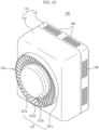
- FIG. 10 is a view illustrating an indoor unit of an air conditioner according to another embodiment of the present invention
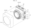
- FIG. 11 is a view illustrating the indoor unit shown in FIG. 10 , in which the front panel is separated from the indoor unit.
- the indoor unit 200 includes one diagonal flow fan unit 120a, and an opening 112a is provided in the front panel 112 to couple the diagonal flow fan unit 120a to the front panel 112.
- Other configurations and operational mechanism are the same as those of the indoor unit of air conditioner 100 according to the previous embodiment of the present invention and thus a detailed description thereof will be omitted.
- FIG. 12 is a view illustrating an indoor unit of an air conditioner according to another embodiment of the present invention
- FIG. 13 is a cross-sectional view illustrating the indoor unit shown in FIG. 12 .
- a diffuser 121 of a diagonal flow fan unit 120 of an indoor unit 300 includes a guide vane 173 to prevent the diagonal flow fan 123 from being exposed through the discharge outlet 121a and guide flow of air discharged through the discharge outlet 121a.
- the guide vane 173, arranged between a circular disc plate 121b and a grille 121c, may include a first vane 173a spaced apart from the circular disc plate 121b in a circumferential direction and formed in a ring shape, and a second vane 153b extending from the outer circumferential surface of the first vane 173a to the inner circumferential surface of the grille 121c.
- the first vane 173a may include a radial inner surface facing the circular disc plate 121b, and a radial outer surface facing the grille 121c.
- the rear end of the inner surface of the first vane 173a which is positioned at the inner side of the discharge outlet 121a, may be formed to be inclined with respect to the axial direction of the diagonal flow fan 123, as in the case of the flow passage forming duct 124a.
- the inclination angle may decrease as the inner surface extends from the rear end to the front such that the front portion thereof is parallel to the axial direction of the diagonal flow fan 123.
- the rear end of the radial inner lateral surface of the first vane 173a may be formed to have a predetermined inclination with respect to the axial direction of the diagonal flow fan 123, but the inclination may decrease as the radial inner lateral surface extends from the rear end thereof to the front such that the front end thereof is parallel to the axial direction of the diagonal flow fan 123.
- first vane 173a formed as above, part of cool air slantingly discharged by the diagonal flow fan 123 and the flow passage forming part 124a with respect to the axial direction of the diagonal flow fan 123 is guided in the axial direction of the diagonal flow fan 123 through the inner and outer surfaces of the first vane 173a.
- the radial outer surface of the first vane 173a is generally curved outward, and thus the cross section of the first vane 173a may be generally provided in a streamline shape.
- the cool air discharged from the discharge outlet 121a in the direction parallel to the axial direction of the diagonal flow fan 123 by the first vane 173a is guided out of the discharge outlet 121a and allowed to reach a far distance from the discharge outlet 121a, and the cool air discharged from the discharge outlet 121a at an inclination angle with respect to the axial direction of the diagonal flow fan 123 is allowed to reach an area of wide angle from the discharge outlet 121a.
- the second vane 173b may be radially formed in the discharge outlet 121a, and multiple second vanes 173b may be arranged equally spaced apart throughout the entirety of the discharge outlet 121a.
- the second vane 173b may be formed in a curved line to rotate in one direction about the axis of the diagonal flow fan 123 to guide formation of a rotating air stream when the cool air is discharged from the discharge outlet 121a.
- the rotating air stream formed in the discharged air stream may function to extend the discharge distance such that the cool air reaches a considerable distance from the indoor unit 100.
- the diffuser 121 provided with the first vane 173a and the second vane 173b as above may be formed by injection molding, and the first vane 173a and the second vane 173b may be integrated with the grille 121c formed around the circular disc plate 121b and the discharge outlet 121a.
- one first vane 173a is provided in the discharge outlet 121a.
- this is simply for illustration, and a plurality of first vanes 173a may be provided in the discharge outlet 121a in a radial direction.
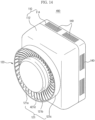
- FIG. 14 is a view illustrating an indoor unit of an air conditioner according to a further embodiment of the present invention.
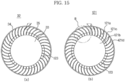
- FIG. 15 is a view showing the shape of a diffuser (a) of an indoor unit of an air conditioner according to the conventional art and the shape of a diffuser (b) of an indoor unit of an air conditioner according to another embodiment of the present invention.
- FIG. 16 is an enlarged view showing section 'B' of FIG. 15
- FIG. 17 is a perspective view of FIG. 16 .
- a diffuser 121 of a diagonal flow fan unit 120 of an indoor unit 400 includes a circular disc plate 121b, a circular grille 121c coupled to the outer circumferential surface of the circular disc plate 121b, a ring-shaped discharge outlet 121a formed between the circular disc plate 121b and the grille 121c.
- the diffuser 121 is disposed at the front of a diagonal flow fan 123 to discharge the air passing the diagonal flow fan 123 to the outside of the front panel 112 through the discharge outlet 121a.
- the grille 121c includes blade plates 421d, and the flow direction and flow rate of the air discharged through the discharge outlet 121a may be adjusted by changing the number, shape and orientation of the blade plates 421d.
- the blade plate 421d is formed in the shape of a spiral blade to extend from the circular disc plate 121b to the grille 121c, and thereby guiding discharge of the air blowing from the diagonal flow fan 123 to the outside.
- the blade plate 421d is formed to extend from the circular disc plate 121b to the grille 121c in a first direction.
- the first direction which may be one of various directions including a spiral direction and a radial direction extending from the circular disc plate 121b to the grille 121c, is assumed to be the radial direction in the illustrated embodiment.
- the blade plate 421d extends in the first direction and is curved in a direction opposite to that of rotation of the diagonal flow fan 123. If the diagonal flow fan 123 rotates clockwise when viewed from the front of the diffuser 121, the blade plate 421d extends from the circular disc plate 121b to the grille 121c and is curved counterclockwise. If the diagonal flow fan 123 rotates counterclockwise, the blade plate 421d extends from the circular disc plate 121b to the grille 121c and is curved clockwise.
- the blade plate 35 extends from a disc plate 33 to a grille 34 and is curved clockwise, i.e., if the blade plate 35 is curved in the same direction as that of rotation of the diagonal flow fan 123, the discharged air blowing from the diagonal flow fan 123 is guided by the blade plate 35 to form a diffuse air stream rather than a front air stream.
- diffusing of the discharged air in all directions is blocked and instead the diffuse air stream is transformed into a front air stream by the blade plate 421d.
- the axis lying in the direction toward the front of the diffuser 121 is defined as the z-axis
- the axis lying in a radial direction toward the center of the diffuser 121 is defined as the y-axis
- the axis lying in the direction of the tangent line of the diffuser 121 having a circular shape is defined as the x-axis
- the shape of the spiral blade of the blade plate 421d may be formed by a rib having a predetermined width.
- the blade plate 421d serves to protect the internal components of the indoor unit 100 such as the diagonal flow fan 123, but is primarily intended to guide discharged air from the diagonal flow fan 123 to form an air stream. Therefore, the blade plate 421d is formed by a rib having a predetermined width sufficient to guide the discharged air.
- Curving the front portion 422 and the rear portion 424 at different angles is more effective in forming a front air stream.
- the rear portion 424 is more curved than the front portion 422 in consideration of formation of a front air stream.
- the rear portion 424 is more curved than the front portion 422, and thus as the blade plate 421d extends from the rear portion 424 to the front portion 422, the lateral surface of the blade plate 421d becomes approximately parallel to the front surface of the diffuser 121, i.e., to the z-axis.
- the air discharged from the diagonal flow fan 123 is first guided by the rear portion 424 along the lateral surface of the blade plate 421d and is then guided by the front portion 422 toward the front of the diffuser 123 to form a front air stream.
- the grille 121c is formed in an annular shape. Thereby, when the discharged air from the diagonal flow fan 123 is discharged through the discharge outlet 121a in the front direction of the front panel 112, the grille 121c serves to prevent the discharged air stream from being diffused upward, downward leftward and rightward and guide the discharged air.
- the flow direction and flow rate of the air discharged through the discharge outlet 121a may be adjusted by widening or narrowing the radial width of the discharge outlet 121a through adjustment of the distance between the circular disc plate 121b and the grille 121c, or by adjusting the diameter of the circular disc plate 121b.
- FIGS. 18 to FIG. 20 are views illustrating flows of discharged air generated by a diffuser of an indoor unit of an air conditioner according to the conventional art and a diffuser of an indoor unit of an air conditioner according to another embodiment of the present invention.
- the direction of rotation of the diagonal flow fan 123 is opposite to the direction in which the blade plate 421d is curved, and therefore the discharged air from the diagonal flow fan 123 is prevented from being diffused by the blade plate 421d, but is directed in the forward direction as it is guided from the rear portion 424 to the front portion 422 of the blade plate 421d.
- orientation of the blade plate 35 in the direction of rotation of the diagonal flow fan 123 further develops diffuse air stream in the discharged air, causing the discharged air to diffuse in all directions from the front of the air conditioner.
- the blade plate 421d curved in the direction opposite to the direction of rotation of the diagonal flow fan 123 develops a front air stream more than a diffuse air stream, thereby allowing the front air stream to be transferred a great distance from the front of the air conditioner.
- an indoor unit of an air conditioner has a suction inlet, a heat exchanger, a diagonal flow fan and a discharge outlet arranged in a row and thus simplifies the air flow passage, and thereby the efficiency of the indoor unit may increase and a compact size thereof may be realized.
- multiple diagonal flow fans are independently controllable to facilitate adjustment of the flow direction and flow rate of air, and therefore convenience in using the indoor unit may be enhanced.
Landscapes
- Engineering & Computer Science (AREA)
- Chemical & Material Sciences (AREA)
- Combustion & Propulsion (AREA)
- Mechanical Engineering (AREA)
- General Engineering & Computer Science (AREA)
- Air-Conditioning Room Units, And Self-Contained Units In General (AREA)
- Air Filters, Heat-Exchange Apparatuses, And Housings Of Air-Conditioning Units (AREA)
Claims (7)
- Unité intérieure (100, 200, 300, 400) d'un climatiseur comprenant :un boîtier (110) comprenant un panneau avant dans lequel au moins une ouverture (112a) est formée ;au moins un diffuseur (121) disposé au niveau d'une position correspondant à l'au moins une ouverture (112a) et comprenant une sortie de décharge (121a) ;un moteur d'entraînement (122) couplé à une surface arrière du diffuseur (121) ; etun ventilateur à flux diagonal (123) couplé en rotation au moteur d'entraînement (122),ledit diffuseur (121) comprenant :une plaque à disque circulaire (121b) ; etune grille (121c) disposée sur un côté externe d'une surface circonférentielle externe de la plaque à disque circulaire (121b) selon une direction radiale de la plaque à disque circulaire (121b) pour former la sortie de décharge (121a) entre la grille (121c) et la plaque à disque circulaire (121b),ladite grille (121c) comprenant une pluralité de plaques de pale (121d, 421d) s'étendant à partir de la surface circonférentielle externe de la plaque à disque circulaire (121b) jusqu'à une surface circonférentielle interne de la grille (121c) selon la direction radiale de la plaque à disque circulaire (121b), et chaque plaque de pale (121d, 421d) étant formée dans une forme courbée selon une direction opposée à une direction de rotation du ventilateur à flux diagonal (123),chaque plaque de pale (121d, 421d) comprenant une partie avant (422) orientée selon une direction avant et une partie arrière (424) orientée selon une direction arrière, etcaractérisée en ce que la courbure de la partie arrière (424) de chaque plaque de pale (121d, 421d) est supérieure à la courbure de la partie avant (422) de chaque plaque de pale (121d, 421d).
- Unité intérieure selon la revendication 1, une courbure de la plaque de pale (121d, 421d) augmentant à mesure que la plaque de pale (121d, 421d) s'étend à partir de la surface circonférentielle externe de la plaque à disque circulaire (121b).
- Unité intérieure selon l'une quelconque des revendications 1 à 2, chaque plaque de pale (121d, 421d) étant formée par une nervure en spirale.
- Unité intérieure selon l'une quelconque des revendications précédentes, ledit ventilateur (123) comprenant :un moyeu (123a) couplé à l'arbre rotatif (122a) du moteur d'entraînement (122) ; etune pluralité de pales (123b) couplées à une surface circonférentielle externe du moyeu (123a).
- Unité intérieure selon l'une quelconque des revendications précédentes, comprenant en outre :au moins une entrée d'aspiration (140) formée au niveau d'une surface arrière du boîtier (110) ; etun échangeur de chaleur (130) disposé entre le ventilateur (123) et l'entrée d'aspiration (140).
- Unité intérieure selon la revendication 5, ledit boîtier (110) comprenant un panneau avant (112) et un panneau arrière (114) couplé à un arrière du panneau avant (112), et
ladite au moins une ouverture (112a) étant prévue dans le panneau avant (112), et ladite entrée d'aspiration (140) étant prévue dans le panneau arrière (114). - Unité intérieure selon l'une quelconque des revendications précédentes, comprenant en outre :un conduit (124) fixé à une surface arrière du diffuseur (121) et comprenant une plaque de fixation (124b) formée dans une forme rectangulaire ; etun cadre (150) disposé à l'intérieur du boîtier (110) et fixé au conduit (124) à travers la plaque de fixation (124b) pour supporter le diffuseur (121).
Applications Claiming Priority (4)
| Application Number | Priority Date | Filing Date | Title |
|---|---|---|---|
| KR20120070377 | 2012-06-28 | ||
| KR1020120148804A KR102034104B1 (ko) | 2012-06-28 | 2012-12-18 | 공기조화기의 실내기 및 공기조화기의 제어방법 |
| KR1020130036564A KR101271056B1 (ko) | 2012-06-28 | 2013-04-03 | 공기조화기의 실내기 |
| EP13174254.6A EP2679920B1 (fr) | 2012-06-28 | 2013-06-28 | Unité intérieure de climatiseur |
Related Parent Applications (2)
| Application Number | Title | Priority Date | Filing Date |
|---|---|---|---|
| EP13174254.6A Division EP2679920B1 (fr) | 2012-06-28 | 2013-06-28 | Unité intérieure de climatiseur |
| EP13174254.6A Division-Into EP2679920B1 (fr) | 2012-06-28 | 2013-06-28 | Unité intérieure de climatiseur |
Publications (4)
| Publication Number | Publication Date |
|---|---|
| EP3399248A2 EP3399248A2 (fr) | 2018-11-07 |
| EP3399248A3 EP3399248A3 (fr) | 2019-01-23 |
| EP3399248B1 true EP3399248B1 (fr) | 2025-02-12 |
| EP3399248C0 EP3399248C0 (fr) | 2025-02-12 |
Family
ID=48700392
Family Applications (2)
| Application Number | Title | Priority Date | Filing Date |
|---|---|---|---|
| EP18178346.5A Active EP3399248B1 (fr) | 2012-06-28 | 2013-06-28 | Unité intérieure de climatiseur |
| EP13174254.6A Active EP2679920B1 (fr) | 2012-06-28 | 2013-06-28 | Unité intérieure de climatiseur |
Family Applications After (1)
| Application Number | Title | Priority Date | Filing Date |
|---|---|---|---|
| EP13174254.6A Active EP2679920B1 (fr) | 2012-06-28 | 2013-06-28 | Unité intérieure de climatiseur |
Country Status (3)
| Country | Link |
|---|---|
| US (1) | US9551498B2 (fr) |
| EP (2) | EP3399248B1 (fr) |
| CN (1) | CN103528131B (fr) |
Families Citing this family (40)
| Publication number | Priority date | Publication date | Assignee | Title |
|---|---|---|---|---|
| CN104748234B (zh) * | 2015-03-30 | 2018-04-27 | 广东美的制冷设备有限公司 | 空调器 |
| KR102395851B1 (ko) * | 2015-04-08 | 2022-05-10 | 삼성전자주식회사 | 팬 어셈블리 및 이를 포함하는 공기조화기 |
| KR101698842B1 (ko) * | 2015-07-17 | 2017-01-23 | 삼성전자 주식회사 | 공기조화기 및 그 제어방법 |
| US11118792B2 (en) | 2015-07-17 | 2021-09-14 | Samsung Electronics Co., Ltd. | Air conditioner |
| KR101840697B1 (ko) * | 2015-07-17 | 2018-05-04 | 삼성전자 주식회사 | 공기조화기 |
| KR101791056B1 (ko) * | 2015-07-21 | 2017-10-27 | 삼성전자주식회사 | 공기조화기 및 그 제어 방법 |
| US11193677B2 (en) * | 2015-07-21 | 2021-12-07 | Samsung Electronics Co., Ltd. | Air conditioner and control method thereof |
| CN105066243A (zh) * | 2015-07-29 | 2015-11-18 | 广东志高空调有限公司 | 一种空调柜机 |
| CN105156345B (zh) * | 2015-09-11 | 2018-06-22 | 珠海格力电器股份有限公司 | 一种立式空调器 |
| CN105240930B (zh) * | 2015-09-11 | 2017-12-19 | 珠海格力电器股份有限公司 | 风量调节装置的风量调节方法 |
| CN105179273B (zh) * | 2015-09-11 | 2020-06-19 | 珠海格力电器股份有限公司 | 一种空气调节设备 |
| CN105156344B (zh) * | 2015-09-11 | 2018-06-22 | 珠海格力电器股份有限公司 | 一种立式空调器 |
| US20170089593A1 (en) * | 2015-09-30 | 2017-03-30 | Samsung Electronics Co., Ltd. | Air conditioner |
| CN105258217A (zh) * | 2015-10-10 | 2016-01-20 | 深圳创维空调科技有限公司 | 一种立体环抱送风装置及其空调器 |
| CN105258218B (zh) * | 2015-10-10 | 2017-12-12 | 深圳创维空调科技有限公司 | 一种立体环抱送风结构及其空调器 |
| CN105371361B (zh) * | 2015-10-10 | 2017-12-12 | 深圳创维空调科技有限公司 | 一种立体环抱送风结构及其空调器 |
| US10330104B2 (en) * | 2015-10-30 | 2019-06-25 | Lg Electronics Inc. | Air conditioner |
| KR101769817B1 (ko) * | 2015-10-30 | 2017-08-30 | 엘지전자 주식회사 | 가습청정장치 |
| CN105864992A (zh) * | 2016-06-01 | 2016-08-17 | 珠海格力电器股份有限公司 | 空调器、风机系统及其风道结构 |
| CN105864995B (zh) * | 2016-06-01 | 2019-02-01 | 珠海格力电器股份有限公司 | 出风组件及具有其的空调器 |
| CN106288007A (zh) * | 2016-08-25 | 2017-01-04 | 珠海格力电器股份有限公司 | 空调器 |
| CN110869677B (zh) * | 2017-05-18 | 2022-05-13 | 三星电子株式会社 | 空调 |
| DE102017111001A1 (de) * | 2017-05-19 | 2018-11-22 | Ebm-Papst Mulfingen Gmbh & Co. Kg | Ventilationseinheit für Kälteanlagen |
| CN107876230B (zh) * | 2017-11-29 | 2023-05-30 | 九牧厨卫股份有限公司 | 一种摆动水出水芯及出水装置 |
| KR102401667B1 (ko) * | 2017-12-15 | 2022-05-25 | 삼성전자 주식회사 | 공기청정기 및 그 제어방법 |
| JP6789205B2 (ja) * | 2017-12-25 | 2020-11-25 | ダイキン工業株式会社 | 空調ユニットおよび空調システム |
| KR102519060B1 (ko) * | 2017-12-27 | 2023-04-07 | 삼성전자주식회사 | 공기조화기 |
| US11460200B2 (en) * | 2018-08-21 | 2022-10-04 | Kenneth Horvath | Method and apparatus for air circulation and purification |
| KR102609095B1 (ko) * | 2018-11-23 | 2023-12-04 | 삼성전자주식회사 | 공기조화기 및 그 제어방법 |
| KR102662868B1 (ko) * | 2018-12-20 | 2024-05-03 | 삼성전자주식회사 | 공기조화기 |
| CN109520021B (zh) * | 2019-01-08 | 2021-06-18 | 广东美的制冷设备有限公司 | 空调器的控制方法 |
| CN111442352B (zh) * | 2019-01-17 | 2025-03-28 | 青岛海尔空调器有限总公司 | 立式空调器室内机 |
| EP3722685B1 (fr) * | 2019-02-25 | 2023-03-15 | GD Midea Air-Conditioning Equipment Co., Ltd. | Unité intérieure de climatiseur, climatiseur et procédé de commande de climatiseur |
| CN110207258A (zh) * | 2019-06-26 | 2019-09-06 | 广东美的制冷设备有限公司 | 空调器 |
| US12196431B2 (en) * | 2019-12-10 | 2025-01-14 | Lg Electronics Inc. | Air management apparatus or device |
| US11914435B2 (en) * | 2020-03-20 | 2024-02-27 | Mercury Mission Systems, Llc | Systems and methods for fractal cooling |
| CN111412602B (zh) * | 2020-03-31 | 2021-11-23 | 广东美的制冷设备有限公司 | 基于空调器的涡环生成方法、空调器、存储介质及装置 |
| CN114484818A (zh) * | 2020-11-12 | 2022-05-13 | 青岛海尔智能技术研发有限公司 | 射流装置、空调 |
| CN112628862B (zh) * | 2020-12-23 | 2022-08-19 | 青岛海尔空调器有限总公司 | 立柜式空调内机及空调器 |
| CN116438411A (zh) | 2021-03-30 | 2023-07-14 | 三星电子株式会社 | 空调室内机及空调控制方法 |
Citations (1)
| Publication number | Priority date | Publication date | Assignee | Title |
|---|---|---|---|---|
| EP1016790A2 (fr) * | 1998-12-31 | 2000-07-05 | Halla Climate Control Corp. | Stator pour ventilateur axial |
Family Cites Families (33)
| Publication number | Priority date | Publication date | Assignee | Title |
|---|---|---|---|---|
| JPH01134135A (ja) * | 1987-11-18 | 1989-05-26 | Matsushita Electric Ind Co Ltd | 分離型空気調和機の送風装置 |
| JP3092371B2 (ja) * | 1993-01-22 | 2000-09-25 | ダイキン工業株式会社 | 空気調和機用室外機ユニット |
| US6200094B1 (en) * | 1999-06-18 | 2001-03-13 | The United States Of America As Represented By The Administrator Of The National Aeronautics And Space Administration | Wave augmented diffuser for centrifugal compressor |
| CN2384157Y (zh) * | 1999-07-23 | 2000-06-21 | 张永龙 | 可形成多向扰流之出风栅板 |
| JP2003035438A (ja) * | 2001-07-24 | 2003-02-07 | Hitachi Ltd | 空気調和機用室外ユニット |
| US7249931B2 (en) * | 2002-03-30 | 2007-07-31 | University Of Central Florida Research Foundation, Inc. | High efficiency air conditioner condenser fan with performance enhancements |
| US7014423B2 (en) * | 2002-03-30 | 2006-03-21 | University Of Central Florida Research Foundation, Inc. | High efficiency air conditioner condenser fan |
| US7191613B2 (en) * | 2002-05-08 | 2007-03-20 | Lg Electronics Inc. | Turbo fan and air conditioner having the same applied thereto |
| KR100479463B1 (ko) * | 2002-08-31 | 2005-03-30 | 삼광공조 주식회사 | 대공간 공조용 디퓨저 |
| JP2004156884A (ja) * | 2002-11-08 | 2004-06-03 | Daikin Ind Ltd | 送風ユニットのファンガード |
| JP2004301451A (ja) * | 2003-03-31 | 2004-10-28 | Toshiba Kyaria Kk | 空気調和装置の室外機 |
| AU2004271060B2 (en) * | 2003-09-04 | 2008-07-17 | Lg Electronics Inc. | Indoor unit in air conditioner |
| KR100575304B1 (ko) * | 2003-12-19 | 2006-05-02 | 엘지전자 주식회사 | 공기조화기의 실내기 |
| TWI273879B (en) * | 2004-11-05 | 2007-02-11 | Delta Electronics Inc | Fan and frame thereof |
| JP2006029702A (ja) | 2004-07-16 | 2006-02-02 | Daikin Ind Ltd | 空気調和機 |
| CN2784792Y (zh) | 2005-03-21 | 2006-05-31 | 河南新飞电器有限公司 | 一种分体式空调器室内机 |
| US7687748B2 (en) * | 2005-08-01 | 2010-03-30 | Western Industries, Inc. | Induction cook top system with integrated ventilator |
| KR100755139B1 (ko) * | 2005-10-05 | 2007-09-04 | 엘지전자 주식회사 | 공기 조화기 |
| US20070129001A1 (en) * | 2005-12-02 | 2007-06-07 | Lasko Holdings, Inc. | Portable air moving device with air stream intensity adjustment |
| JP2007162521A (ja) * | 2005-12-12 | 2007-06-28 | Matsushita Electric Ind Co Ltd | 斜流送風機羽根車及び空気調和機 |
| KR20070087829A (ko) | 2005-12-26 | 2007-08-29 | 엘지전자 주식회사 | 공기조화기의 실내기 |
| CN201126218Y (zh) * | 2006-12-01 | 2008-10-01 | 拉斯科控股公司 | 具有气流强度调节的便携式空气移动装置 |
| KR20090043715A (ko) * | 2007-10-30 | 2009-05-07 | 삼성전자주식회사 | 팬가드 및 이를 갖는 공기조화기의 실외기 |
| US8408884B2 (en) * | 2008-04-25 | 2013-04-02 | Delta Electronics, Inc. | Fan and airflow guiding structure thereof |
| TWI350886B (en) | 2008-04-25 | 2011-10-21 | Delta Electronics Inc | Fan and airflow guiding structure thereof |
| CN101608634A (zh) * | 2008-06-19 | 2009-12-23 | 鸿富锦精密工业(深圳)有限公司 | 风扇组合 |
| KR101577071B1 (ko) | 2009-04-30 | 2015-12-11 | 엘지전자 주식회사 | 공기조화장치의 실내기 |
| AU2010286350A1 (en) * | 2009-08-31 | 2012-04-26 | Kaip Pty Limited | An air diffuser and an air circulation system |
| KR20110055840A (ko) * | 2009-11-20 | 2011-05-26 | 삼성전자주식회사 | 공기조화기와 그 실외기 |
| DE102010016377B3 (de) * | 2010-03-16 | 2011-09-22 | Dr. Schneider Kunststoffwerke Gmbh | Luftdüse |
| JP2012002370A (ja) * | 2010-06-14 | 2012-01-05 | Mitsubishi Electric Corp | 空気調和機の室内機、及び空気調和機 |
| JP2012026402A (ja) | 2010-07-27 | 2012-02-09 | Panasonic Corp | 斜流ファン及びこれを備えた空気調和機 |
| JP5220068B2 (ja) | 2010-08-04 | 2013-06-26 | 三菱電機株式会社 | 空気調和機の室内機、及び空気調和機 |
-
2013
- 2013-06-27 US US13/928,910 patent/US9551498B2/en active Active
- 2013-06-28 EP EP18178346.5A patent/EP3399248B1/fr active Active
- 2013-06-28 EP EP13174254.6A patent/EP2679920B1/fr active Active
- 2013-06-28 CN CN201310269631.9A patent/CN103528131B/zh active Active
Patent Citations (1)
| Publication number | Priority date | Publication date | Assignee | Title |
|---|---|---|---|---|
| EP1016790A2 (fr) * | 1998-12-31 | 2000-07-05 | Halla Climate Control Corp. | Stator pour ventilateur axial |
Also Published As
| Publication number | Publication date |
|---|---|
| EP3399248A3 (fr) | 2019-01-23 |
| US20140000852A1 (en) | 2014-01-02 |
| CN103528131A (zh) | 2014-01-22 |
| EP3399248C0 (fr) | 2025-02-12 |
| EP2679920C0 (fr) | 2024-11-13 |
| EP2679920A2 (fr) | 2014-01-01 |
| CN103528131B (zh) | 2016-08-24 |
| US9551498B2 (en) | 2017-01-24 |
| EP3399248A2 (fr) | 2018-11-07 |
| EP2679920A3 (fr) | 2018-07-11 |
| EP2679920B1 (fr) | 2024-11-13 |
Similar Documents
| Publication | Publication Date | Title |
|---|---|---|
| EP3399248B1 (fr) | Unité intérieure de climatiseur | |
| KR102034104B1 (ko) | 공기조화기의 실내기 및 공기조화기의 제어방법 | |
| US10436496B2 (en) | Indoor unit for air-conditioning apparatus | |
| TWI731570B (zh) | 離心式送風機、送風裝置、空調裝置及冷凍循環裝置 | |
| KR102077572B1 (ko) | 팬어셈블리 | |
| KR20180125425A (ko) | 공기조화기 | |
| US9759220B2 (en) | Cross flow fan and indoor unit of air-conditioning apparatus | |
| CN103574775A (zh) | 空调的室内单元 | |
| US11319961B2 (en) | Centrifugal blower, air conditioner, and refrigeration cycle apparatus | |
| KR20090038555A (ko) | 토출풍향 제어장치를 구비한 공기조화기 | |
| KR102809591B1 (ko) | 공기조화기 및 그 제어방법 | |
| US11029058B2 (en) | Air conditioner | |
| KR20140034383A (ko) | 공기조화기 | |
| JP2011080368A (ja) | 空気調和機のダブルプラグファン構造 | |
| KR20190111347A (ko) | 공기 조화기의 실외기 | |
| KR20220135567A (ko) | 공기조화기의 실내기 및 공기조화기의 제어방법 | |
| US11635213B2 (en) | Air conditioner indoor unit, air conditioner, and method for controlling air conditioner | |
| KR20140014409A (ko) | 공기조화기의 실내기 | |
| US12292204B2 (en) | Air conditioner | |
| US20230213213A1 (en) | Air conditioner | |
| CN211575261U (zh) | 空调柜机和具有其的空调器 | |
| KR20230096515A (ko) | 공기조화기 | |
| CN109642582A (zh) | 空气调节机 | |
| KR20230106451A (ko) | 공기조화기 | |
| KR20250148174A (ko) | 공기조화기 |
Legal Events
| Date | Code | Title | Description |
|---|---|---|---|
| PUAI | Public reference made under article 153(3) epc to a published international application that has entered the european phase |
Free format text: ORIGINAL CODE: 0009012 |
|
| STAA | Information on the status of an ep patent application or granted ep patent |
Free format text: STATUS: THE APPLICATION HAS BEEN PUBLISHED |
|
| AC | Divisional application: reference to earlier application |
Ref document number: 2679920 Country of ref document: EP Kind code of ref document: P |
|
| AK | Designated contracting states |
Kind code of ref document: A2 Designated state(s): AL AT BE BG CH CY CZ DE DK EE ES FI FR GB GR HR HU IE IS IT LI LT LU LV MC MK MT NL NO PL PT RO RS SE SI SK SM TR |
|
| AX | Request for extension of the european patent |
Extension state: BA ME |
|
| PUAL | Search report despatched |
Free format text: ORIGINAL CODE: 0009013 |
|
| AK | Designated contracting states |
Kind code of ref document: A3 Designated state(s): AL AT BE BG CH CY CZ DE DK EE ES FI FR GB GR HR HU IE IS IT LI LT LU LV MC MK MT NL NO PL PT RO RS SE SI SK SM TR |
|
| AX | Request for extension of the european patent |
Extension state: BA ME |
|
| RIC1 | Information provided on ipc code assigned before grant |
Ipc: F24F 1/00 20110101AFI20181214BHEP |
|
| STAA | Information on the status of an ep patent application or granted ep patent |
Free format text: STATUS: REQUEST FOR EXAMINATION WAS MADE |
|
| 17P | Request for examination filed |
Effective date: 20190423 |
|
| RBV | Designated contracting states (corrected) |
Designated state(s): AL AT BE BG CH CY CZ DE DK EE ES FI FR GB GR HR HU IE IS IT LI LT LU LV MC MK MT NL NO PL PT RO RS SE SI SK SM TR |
|
| STAA | Information on the status of an ep patent application or granted ep patent |
Free format text: STATUS: EXAMINATION IS IN PROGRESS |
|
| 17Q | First examination report despatched |
Effective date: 20200331 |
|
| GRAP | Despatch of communication of intention to grant a patent |
Free format text: ORIGINAL CODE: EPIDOSNIGR1 |
|
| STAA | Information on the status of an ep patent application or granted ep patent |
Free format text: STATUS: GRANT OF PATENT IS INTENDED |
|
| INTG | Intention to grant announced |
Effective date: 20240919 |
|
| GRAS | Grant fee paid |
Free format text: ORIGINAL CODE: EPIDOSNIGR3 |
|
| GRAA | (expected) grant |
Free format text: ORIGINAL CODE: 0009210 |
|
| STAA | Information on the status of an ep patent application or granted ep patent |
Free format text: STATUS: THE PATENT HAS BEEN GRANTED |
|
| AC | Divisional application: reference to earlier application |
Ref document number: 2679920 Country of ref document: EP Kind code of ref document: P |
|
| AK | Designated contracting states |
Kind code of ref document: B1 Designated state(s): AL AT BE BG CH CY CZ DE DK EE ES FI FR GB GR HR HU IE IS IT LI LT LU LV MC MK MT NL NO PL PT RO RS SE SI SK SM TR |
|
| REG | Reference to a national code |
Ref country code: GB Ref legal event code: FG4D |
|
| REG | Reference to a national code |
Ref country code: CH Ref legal event code: EP |
|
| REG | Reference to a national code |
Ref country code: DE Ref legal event code: R096 Ref document number: 602013086505 Country of ref document: DE |
|
| REG | Reference to a national code |
Ref country code: IE Ref legal event code: FG4D |
|
| U01 | Request for unitary effect filed |
Effective date: 20250225 |
|
| U07 | Unitary effect registered |
Designated state(s): AT BE BG DE DK EE FI FR IT LT LU LV MT NL PT RO SE SI Effective date: 20250303 |
|
| PG25 | Lapsed in a contracting state [announced via postgrant information from national office to epo] |
Ref country code: RS Free format text: LAPSE BECAUSE OF FAILURE TO SUBMIT A TRANSLATION OF THE DESCRIPTION OR TO PAY THE FEE WITHIN THE PRESCRIBED TIME-LIMIT Effective date: 20250512 |
|
| PG25 | Lapsed in a contracting state [announced via postgrant information from national office to epo] |
Ref country code: PL Free format text: LAPSE BECAUSE OF FAILURE TO SUBMIT A TRANSLATION OF THE DESCRIPTION OR TO PAY THE FEE WITHIN THE PRESCRIBED TIME-LIMIT Effective date: 20250212 |
|
| PG25 | Lapsed in a contracting state [announced via postgrant information from national office to epo] |
Ref country code: ES Free format text: LAPSE BECAUSE OF FAILURE TO SUBMIT A TRANSLATION OF THE DESCRIPTION OR TO PAY THE FEE WITHIN THE PRESCRIBED TIME-LIMIT Effective date: 20250212 |
|
| PGFP | Annual fee paid to national office [announced via postgrant information from national office to epo] |
Ref country code: GB Payment date: 20250520 Year of fee payment: 13 |
|
| PG25 | Lapsed in a contracting state [announced via postgrant information from national office to epo] |
Ref country code: IS Free format text: LAPSE BECAUSE OF FAILURE TO SUBMIT A TRANSLATION OF THE DESCRIPTION OR TO PAY THE FEE WITHIN THE PRESCRIBED TIME-LIMIT Effective date: 20250612 Ref country code: NO Free format text: LAPSE BECAUSE OF FAILURE TO SUBMIT A TRANSLATION OF THE DESCRIPTION OR TO PAY THE FEE WITHIN THE PRESCRIBED TIME-LIMIT Effective date: 20250512 |
|
| PG25 | Lapsed in a contracting state [announced via postgrant information from national office to epo] |
Ref country code: HR Free format text: LAPSE BECAUSE OF FAILURE TO SUBMIT A TRANSLATION OF THE DESCRIPTION OR TO PAY THE FEE WITHIN THE PRESCRIBED TIME-LIMIT Effective date: 20250212 |
|
| PG25 | Lapsed in a contracting state [announced via postgrant information from national office to epo] |
Ref country code: GR Free format text: LAPSE BECAUSE OF FAILURE TO SUBMIT A TRANSLATION OF THE DESCRIPTION OR TO PAY THE FEE WITHIN THE PRESCRIBED TIME-LIMIT Effective date: 20250513 |
|
| U20 | Renewal fee for the european patent with unitary effect paid |
Year of fee payment: 13 Effective date: 20250624 |
|
| PG25 | Lapsed in a contracting state [announced via postgrant information from national office to epo] |
Ref country code: SM Free format text: LAPSE BECAUSE OF FAILURE TO SUBMIT A TRANSLATION OF THE DESCRIPTION OR TO PAY THE FEE WITHIN THE PRESCRIBED TIME-LIMIT Effective date: 20250212 |
|
| PG25 | Lapsed in a contracting state [announced via postgrant information from national office to epo] |
Ref country code: CZ Free format text: LAPSE BECAUSE OF FAILURE TO SUBMIT A TRANSLATION OF THE DESCRIPTION OR TO PAY THE FEE WITHIN THE PRESCRIBED TIME-LIMIT Effective date: 20250212 |
|
| PG25 | Lapsed in a contracting state [announced via postgrant information from national office to epo] |
Ref country code: SK Free format text: LAPSE BECAUSE OF FAILURE TO SUBMIT A TRANSLATION OF THE DESCRIPTION OR TO PAY THE FEE WITHIN THE PRESCRIBED TIME-LIMIT Effective date: 20250212 |
|
| PLBE | No opposition filed within time limit |
Free format text: ORIGINAL CODE: 0009261 |
|
| STAA | Information on the status of an ep patent application or granted ep patent |
Free format text: STATUS: NO OPPOSITION FILED WITHIN TIME LIMIT |
|
| REG | Reference to a national code |
Ref country code: CH Ref legal event code: L10 Free format text: ST27 STATUS EVENT CODE: U-0-0-L10-L00 (AS PROVIDED BY THE NATIONAL OFFICE) Effective date: 20251224 |
|
| 26N | No opposition filed |
Effective date: 20251113 |
|
| REG | Reference to a national code |
Ref country code: CH Ref legal event code: H13 Free format text: ST27 STATUS EVENT CODE: U-0-0-H10-H13 (AS PROVIDED BY THE NATIONAL OFFICE) Effective date: 20260127 |
|
| PG25 | Lapsed in a contracting state [announced via postgrant information from national office to epo] |
Ref country code: MC Free format text: LAPSE BECAUSE OF FAILURE TO SUBMIT A TRANSLATION OF THE DESCRIPTION OR TO PAY THE FEE WITHIN THE PRESCRIBED TIME-LIMIT Effective date: 20250212 |
|
| PG25 | Lapsed in a contracting state [announced via postgrant information from national office to epo] |
Ref country code: IE Free format text: LAPSE BECAUSE OF NON-PAYMENT OF DUE FEES Effective date: 20250628 |
|
| PG25 | Lapsed in a contracting state [announced via postgrant information from national office to epo] |
Ref country code: CH Free format text: LAPSE BECAUSE OF NON-PAYMENT OF DUE FEES Effective date: 20250630 |