EP3399272A1 - Ensemble distributeur de fluide pour échangeurs de chaleur - Google Patents
Ensemble distributeur de fluide pour échangeurs de chaleur Download PDFInfo
- Publication number
- EP3399272A1 EP3399272A1 EP17425047.2A EP17425047A EP3399272A1 EP 3399272 A1 EP3399272 A1 EP 3399272A1 EP 17425047 A EP17425047 A EP 17425047A EP 3399272 A1 EP3399272 A1 EP 3399272A1
- Authority
- EP
- European Patent Office
- Prior art keywords
- holes
- perforated plate
- heat exchanger
- fluid
- perforated
- Prior art date
- Legal status (The legal status is an assumption and is not a legal conclusion. Google has not performed a legal analysis and makes no representation as to the accuracy of the status listed.)
- Granted
Links
Images









Classifications
-
- F—MECHANICAL ENGINEERING; LIGHTING; HEATING; WEAPONS; BLASTING
- F28—HEAT EXCHANGE IN GENERAL
- F28F—DETAILS OF HEAT-EXCHANGE AND HEAT-TRANSFER APPARATUS, OF GENERAL APPLICATION
- F28F9/00—Casings; Header boxes; Auxiliary supports for elements; Auxiliary members within casings
- F28F9/02—Header boxes; End plates
- F28F9/026—Header boxes; End plates with static flow control means, e.g. with means for uniformly distributing heat exchange media into conduits
- F28F9/0278—Header boxes; End plates with static flow control means, e.g. with means for uniformly distributing heat exchange media into conduits in the form of stacked distribution plates or perforated plates arranged over end plates
-
- F—MECHANICAL ENGINEERING; LIGHTING; HEATING; WEAPONS; BLASTING
- F28—HEAT EXCHANGE IN GENERAL
- F28F—DETAILS OF HEAT-EXCHANGE AND HEAT-TRANSFER APPARATUS, OF GENERAL APPLICATION
- F28F9/00—Casings; Header boxes; Auxiliary supports for elements; Auxiliary members within casings
- F28F9/02—Header boxes; End plates
- F28F9/026—Header boxes; End plates with static flow control means, e.g. with means for uniformly distributing heat exchange media into conduits
- F28F9/027—Header boxes; End plates with static flow control means, e.g. with means for uniformly distributing heat exchange media into conduits in the form of distribution pipes
- F28F9/0275—Header boxes; End plates with static flow control means, e.g. with means for uniformly distributing heat exchange media into conduits in the form of distribution pipes with multiple branch pipes
-
- F—MECHANICAL ENGINEERING; LIGHTING; HEATING; WEAPONS; BLASTING
- F28—HEAT EXCHANGE IN GENERAL
- F28D—HEAT-EXCHANGE APPARATUS, NOT PROVIDED FOR IN ANOTHER SUBCLASS, IN WHICH THE HEAT-EXCHANGE MEDIA DO NOT COME INTO DIRECT CONTACT
- F28D7/00—Heat-exchange apparatus having stationary tubular conduit assemblies for both heat-exchange media, the media being in contact with different sides of a conduit wall
- F28D7/16—Heat-exchange apparatus having stationary tubular conduit assemblies for both heat-exchange media, the media being in contact with different sides of a conduit wall the conduits being arranged in parallel spaced relation
-
- F—MECHANICAL ENGINEERING; LIGHTING; HEATING; WEAPONS; BLASTING
- F28—HEAT EXCHANGE IN GENERAL
- F28D—HEAT-EXCHANGE APPARATUS, NOT PROVIDED FOR IN ANOTHER SUBCLASS, IN WHICH THE HEAT-EXCHANGE MEDIA DO NOT COME INTO DIRECT CONTACT
- F28D7/00—Heat-exchange apparatus having stationary tubular conduit assemblies for both heat-exchange media, the media being in contact with different sides of a conduit wall
- F28D7/16—Heat-exchange apparatus having stationary tubular conduit assemblies for both heat-exchange media, the media being in contact with different sides of a conduit wall the conduits being arranged in parallel spaced relation
- F28D7/1607—Heat-exchange apparatus having stationary tubular conduit assemblies for both heat-exchange media, the media being in contact with different sides of a conduit wall the conduits being arranged in parallel spaced relation with particular pattern of flow of the heat exchange media, e.g. change of flow direction
-
- F—MECHANICAL ENGINEERING; LIGHTING; HEATING; WEAPONS; BLASTING
- F28—HEAT EXCHANGE IN GENERAL
- F28F—DETAILS OF HEAT-EXCHANGE AND HEAT-TRANSFER APPARATUS, OF GENERAL APPLICATION
- F28F13/00—Arrangements for modifying heat-transfer, e.g. increasing, decreasing
- F28F13/06—Arrangements for modifying heat-transfer, e.g. increasing, decreasing by affecting the pattern of flow of the heat-exchange media
-
- F—MECHANICAL ENGINEERING; LIGHTING; HEATING; WEAPONS; BLASTING
- F28—HEAT EXCHANGE IN GENERAL
- F28F—DETAILS OF HEAT-EXCHANGE AND HEAT-TRANSFER APPARATUS, OF GENERAL APPLICATION
- F28F9/00—Casings; Header boxes; Auxiliary supports for elements; Auxiliary members within casings
- F28F9/02—Header boxes; End plates
- F28F9/026—Header boxes; End plates with static flow control means, e.g. with means for uniformly distributing heat exchange media into conduits
- F28F9/0265—Header boxes; End plates with static flow control means, e.g. with means for uniformly distributing heat exchange media into conduits by using guiding means or impingement means inside the header box
-
- F—MECHANICAL ENGINEERING; LIGHTING; HEATING; WEAPONS; BLASTING
- F28—HEAT EXCHANGE IN GENERAL
- F28F—DETAILS OF HEAT-EXCHANGE AND HEAT-TRANSFER APPARATUS, OF GENERAL APPLICATION
- F28F9/00—Casings; Header boxes; Auxiliary supports for elements; Auxiliary members within casings
- F28F9/02—Header boxes; End plates
- F28F9/026—Header boxes; End plates with static flow control means, e.g. with means for uniformly distributing heat exchange media into conduits
- F28F9/027—Header boxes; End plates with static flow control means, e.g. with means for uniformly distributing heat exchange media into conduits in the form of distribution pipes
- F28F9/0273—Header boxes; End plates with static flow control means, e.g. with means for uniformly distributing heat exchange media into conduits in the form of distribution pipes with multiple holes
Definitions
- the present invention refers to a fluid distributor assembly for a generic heat exchanger typology and, more specifically, for a shell-and-tube heat exchanger.
- a heat exchanger is a device used to transfer heat between two or more fluids.
- a shell-and-tube heat exchanger usually comprises a plurality of tubes arranged parallel to each other in order to form one or more tube bundles 100 (see figure 1 ).
- the tube bundle 100 is axially inserted into a shell 102 having an elongated shape and a cylindrical geometry.
- the uniform distribution of the first fluid among all the tubes of the tube bundle is one of the objectives to be achieved in order to optimize the use of the heat exchanger surface.
- the fluid distribution can be the distribution of a refrigerant inside the tubes of a dry-expansion shell-and-tube evaporator, or the uniform distribution of the second fluid on the external surface of the tube bundle, e.g. the distribution of the refrigerant upon the external surface of the tubes in a falling-film shell-and-tube evaporator, or, in the case of a compact heat exchanger, i.e. a plate heat exchanger with open channels (also opened only from the side of the fluid to be distributed), the fluid distribution among the different parallel channels and within each channel.
- the heat exchanger is an evaporator in which the fluid to be distributed is, for example, a refrigerant in the two-phase vapor-liquid physical state
- the distribution of the fluid both in terms of mass flow rate and vapor quality for tube/channel/channel section, is penalized by the different fluid-dynamic behavior between the two phases.
- Heat exchangers are thus commonly provided with fluid distribution systems having one or both of the following objectives:
- the introduction in the distribution system of a high pressure drop localized at the entrance of each tube/channel/channel section (for example through orifices), wherein said high pressure drop is much greater than those corresponding to the crossing of the fluid along the entire heat exchanger length inside the headers and tubes or channels, will ensure a good distribution because there will be less influence of the path length difference of the "path-lines" in which the entire flow of the fluid is divided along the entire heat exchanger length (inlet header, tube/channel, outlet header).
- the generated pressure drop varies greatly with the type of application, so primarily considering the refrigerant type, the mass flow rate, the vapor quality, the temperature and/or the pressure.
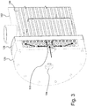
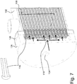
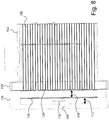
- Typical examples of fluid distribution systems according to the prior art are shown in the attached figures 1 to 11 .
- the fluid distribution system consists of a flow-break disk 108 placed at the first fluid inlet pipe 104.
- the fluid distribution system consists of a flow-break perforated disk 110.
- the fluid distribution system consists of a pre-chamber 112 obtained using a single perforated plate 114 adherent to the tube-sheet, or placed at a certain distance from the tube-sheet, with or without a flow-break perforated disk 110.
- the fluid distribution system consists of a pre-chamber 112 obtained using a single device 116 for each tube/channel/channel section with calibrated orifice per device, with or without a flow-break perforated disk 110.
- the fluid distribution system consists of a pre-chamber 112 and at least a subsequent chamber 118 obtained assembling a number of perforated plates 120 (with a symmetric or asymmetric holes distribution) at a predefined distance from each other, with or without a flow-break perforated disk 110.
- the fluid distribution system consists of a pre-chamber 112 and a perforated plate 122 with a capillary tube for each tube/channel/channel section, wherein an equalization chamber 124, formed between the perforated plate 122 and the inlet header or tube-sheet, can be present or not.
- Document US 6868695 describes a flow distributor for an evaporator having at least three perforated plates defining chambers to ensure even distribution of liquid refrigerant.
- Document US 2014/0223936 describes a construction of a refrigerant displacement array consisting of a series of alternating spacers and perforated baffle plates.
- Document CN 102954628 describes a liquid distributor for an evaporator having staggered perforated distribution plates.
- fluid distribution systems of the type shown in figures 1-3 may cause an inefficient distribution of the fluid.
- fluid distribution systems of figures 4-7 an efficient distribution can be obtained only in a limited range of applications, due to a limit of manufacturing at a low cost.
- the limit is linked to the possibility that a single hole, or a single orifice, can have a size that can be manufactured with a low cost technology (e.g. punching) and generate the required pressure drop for the specific application.
- One object of the present invention is therefore to provide a fluid distributor assembly for a heat exchanger device which is capable of resolving the above mentioned drawbacks of the prior art in a simple, inexpensive and particularly functional manner.
- one object of the present invention is to provide a fluid distributor assembly for a heat exchanger which is capable of performing a good distribution of the fluid.
- Another object of the present invention is to provide a fluid distributor assembly for a heat exchanger which is capable of providing a wide variability of configurations in the assembly phase of its sub-components, in order to ensure an optimal solution for each specific application in a wide possible range.
- a further object of the present invention is to provide a fluid distributor assembly for a heat exchanger which is capable of maintaining a constant geometry during operation.
- Still another object of the present invention is to provide a fluid distributor assembly for a heat exchanger which provides the possibility of assembling the sub-components in order to minimize, or even eliminate, the reverse flow instability problems.
- a heat exchanger is a shell-and-tube heat exchanger and is shown with illustrative but not limiting purposes.
- the shell-and-tube heat exchanger is of the type comprising a plurality of tubes arranged parallel to each other in order to form one or more tube bundles 100.
- Each tube bundle 100 is axially inserted into a shell 102 having an elongated shape and a cylindrical geometry.
- the tubes of the tube bundle 100 can be of any shape, like U-shaped or straight.
- At least one end of each tube of the tube bundle 100 is joined to an inlet tube-sheet 128, disposed downstream of the head portion 126 (with respect to the flow direction of the first fluid entering the one or more first inlet pipes 104) and provided with respective tube-sheet bores 130 for inletting the first fluid in the tubes of the tube bundle 100.
- the inlet tube-sheet 128 thus separates the second fluid from the first fluid.
- the fluid distributor assembly 10 is placed at the one or more first inlet pipes 104 and, more specifically, between the head portion 126 and the inlet tube-sheet 128 of the shell-and-tube heat exchanger.
- the fluid distributor assembly 10 consists in assembling an adequate number, greater than or equal to two, of perforated plates 12A, 12B, 12C, 12D, in such a way that in the space between two subsequent plates 12A, 12B an equalization closed chamber 14 is obtained.
- Each equalization closed chamber 14 is provided with a hermetic seal device 16 on the edges, in order to progressively improve the fluid distribution efficiency in the passage through each perforated plate 12A, 12B, 12C, 12D.
- the fluid distributor assembly 10 is provided with a first perforated plate 12A, in turn provided with first through holes 20A, and with at least one second perforated plate 12B, in turn provided with second through holes 20B.
- the at least one second perforated plate 12B is disposed parallel and downstream of the first perforated plate 12A with respect to the flow direction A of the first fluid flowing into the first through holes 20A and the second through holes 20B.
- a hermetic seal device 16 is disposed between the first perforated plate 12A and the at least one second perforated plate 12B.
- the first perforated plate 12A and the at least one second perforated plate 12B are spaced from each other, in such a way that the first perforated plate 12A and the at least one second perforated plate 12B, together with the hermetic seal device 16, surround an equalization chamber 14 of predefined depth, measured along the flow direction A of the first fluid flowing into the first through holes 20A and the second through holes 20B.
- Each equalization chamber 14 is closed at the peripheral edges of the first perforated plate 12A and of the at least one second perforated plate 12B.
- the equalization chamber 14 progressively improves the fluid distribution efficiency in the passage through the first through holes 20A of the first perforated plate 12A and the second through holes 20B of the at least one second perforated plate 12B.
- the hermetic seal device 16, and thus each equalization chamber 14, can be obtained with different construction ways, as it will be better explained hereinafter.
- the hermetic seal device 16 can be obtained with one or more ring-spacers 16A, 16B each disposed between two subsequent perforated plates 12A, 12B, 12C, 12D at their peripheral edges.
- Each ring-spacer 16A, 16B can be manufactured with a metallic, or rubber, or plastic material.
- Each ring-spacer 16A, 16B can be assembled with the corresponding perforated plates 12A, 12B, 12C, 12D through a brazing, or welding, or gluing process, or using gaskets or interference joints.
- the first through holes 20A of the first perforated plate 12A are staggered with respect to the second through holes 20B of the at least one second perforated plate 12B.
- the through holes 20A, 20B, 20C, 20D of two subsequent perforated plates 12A, 12B, 12C, 12D are staggered with respect to each other.
- the number of holes 20B of the at least one second perforated plate 12B is equal to, or is a multiple of, the number of the tubes of the tube bundle 100, or the number of the channels in case of a heat exchanger provided with open channels.
- the holes 20B of the at least one second perforated plate 12B are thus placed at the inlet mouth of corresponding tubes or channels.
- the correct number of perforated plates 12A, 12B, 12C, 12D to be assembled in the fluid distributor assembly 10 should be selected according to the following conditions:
- the first two conditions are peculiar and fixed for a specific type of shell-and-tube equipment in a given wide field of use of a specific application (e.g. dry expansion evaporators, single-pass tube, to be used in refrigeration circuits with HFC/HFO refrigerants for air-conditioning applications).
- a specific application e.g. dry expansion evaporators, single-pass tube, to be used in refrigeration circuits with HFC/HFO refrigerants for air-conditioning applications.
- the fluid distributor assembly 10 according to the present invention can be easily designed for an optimal fluid distribution system for each specific application by simply changing the following parameters:
- the result will be a standardization of the most expensive sub-components of the fluid distributor assembly 10.
- An example would be: establish the number of perforated plates 12A, 12B, 12C and the number of the corresponding equalization chambers 14, establish the thickness of the perforated plates 12A, 12B, 12C and the depth of each equalization chamber 14, whereas the diameter of the through holes 20A, 20B, 20C, 20D of each perforated plate 12A, 12B, 12C, 12D is left as the sole variable parameter of the fluid distributor assembly 10.
- the manufacturing cost of the fluid distributor assembly 10 will not be too affected, another possibility could be to vary the thickness of the perforated plates 12A, 12B, 12C, 12D in order to achieve the goal of having high pressure drops.
- the thickness increase can be obtained on each single perforated plate 12A, 12B, 12C, 12D.
- one or more of the perforated plates of the fluid distributor assembly 10 can be obtained by the overlap of two or more identical perforated sheets 12C, 12D, 12E ( figure 20 ) of low thickness, wherein each perforated sheet 12C have through holes 20C of the same number, with the same layout and, according to one preferred embodiment, of the same diameter of the corresponding through holes 20D, 20E of the other perforated sheets 12D, 12E.
- a preferred embodiment of the fluid distributor assembly 10 is provided with a pre-chamber 22 interposed between the head portion 126 of the heat exchanger and the first perforated plate 12A of the fluid distributor assembly 10.
- At least a gasket 18 is interposed between the head portion 126 of the heat exchanger and the first perforated plate 12A of the fluid distributor assembly 10. The gasket 18 surrounds and seals the pre-chamber 22 with respect to the head portion 126 of the heat exchanger and the first perforated plate 12A of the fluid distributor assembly 10.
- the preferred embodiment of the fluid distributor assembly 10 thus comprises three perforated plates 12A, 12B and 12C-12D, wherein the third perforated plate 12C-12D is obtained by the overlap of two identical perforated sheets 12C and 12D.
- Two ring-spacers 16A and 16B are respectively provided between the first perforated plate 12A and the second perforated plate 12B, and between the second perforated plate 12B and the third perforated plate 12C-12D.
- the ring-spacers 16A and 16B form two corresponding equalization chambers 14.
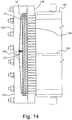
- FIGS 14 and 15 an example of positioning of the fluid distributor assembly 10 in a head portion 126 or inlet head of a heat exchanger is shown. More specifically, the head portion 126 is the inlet head of a shell-and-tube dry-expansion evaporator.
- the hermetic sealing of the equalization chambers 14 shown in figures 12-15 is obtained by brazing using copper foils.
- the perforated plates 12A, 12B, 12C, 12D and the ring-spacers 16A, 16B are manufactured with carbon steel material.
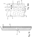
- FIG. 16 Another possible type of sealing between the perforated plates 12A, 12B, 12C, 12D can be obtained with a single resilient case 16 configured for surrounding the peripheral edges of the first perforated plate 12A and of the at least one second perforated plate 12B.
- the resilient case 16 is preferably manufactured with rubber through a molding process.
- the resilient case 16 is provided with a plurality of inner peripheral grooves 24 in which the peripheral edges of corresponding perforated plates 12A, 12B, 12C, 12D can be housed.
- the particular geometry of the resilient case 16 mold makes possible that the same resilient case 16 acts as a spacer between the subsequent perforated plates 12A, 12B, 12C, 12D, creating the closed equalization chambers 14. This solution is shown in figures 16 and 16A .
- both types of sealing assembly between the perforated plates 12A, 12B, 12C, 12D allow certain advantages in terms of manufacturing costs. Actually, it is possible to couple together two or more perforated sheets 12C, 12D, 12E of equal thickness and with a low thickness with respect to the thickness of the perforated plates 12A, 12B, 12C, 12D, with the advantage of keeping low the drilling costs (for example using punching instead of laser).
- each pair of perforated sheets 12C, 12D, 12E can be joined at their peripheral edges by a thin copper sheet, positioned between the two perforated sheets 12C, 12D, 12E before brazing.
- the copper sheet is suitably shaped in such a way that the molten copper in excess will not obstruct the through holes 20C, 20D, 20E of the perforated sheets 12C, 12D, 12E.
- plugs that will work for interference can be used to join together the perforated plates 12A, 12B, 12C, 12D.
- the plugs can be inserted into corresponding plug bores 26 obtained on the peripheral edge of each perforated plate 12A, 12B, 12C, 12D, in order to keep the correct contact, as well as the through holes 20A, 20B, 20C, 20D alignment, between the coupled perforated plates 12A, 12B, 12C, 12D.
- the fluid distributor assembly 10 will include a number of configurations equal to the number of heat exchanger embodiments that are obtained by varying the number of the respective tubes or channels.
- a number of configurations of the through holes 20A, 20B, 20C, 20D layout is available for each perforated plate 12A, 12B, 12C, 12D.
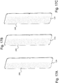
- the through holes 20A, 20B, 20C, 20D number and diameter for each perforated plate 12A, 12B, 12C, 12D may be chosen. More specifically, the perforated plate 12A of figure 17A is provided with seven columns of through holes 20A and is designed for a heat exchanger having seven rows of tubes or channels.
- the perforated plate 12A of figure 17B is provided with eight columns of through holes 20A and is designed for a heat exchanger having eight rows of tubes or channels.
- the perforated plate 12A of figure 17C is provided with nine columns of through holes 20A and is designed for a heat exchanger having nine rows of tubes or channels.
- the perforated plate 12A of figure 17D is provided with ten columns of through holes 20A and is designed for a heat exchanger having ten rows of tubes or channels.
- the perforated plate 12A of figure 17E is provided with eleven columns of through holes 20A and is designed for a heat exchanger having eleven rows of tubes or channels.
- the perforated plate 12A of figure 17F is provided with twelve columns of through holes 20A and is designed for a heat exchanger having twelve rows of tubes or channels.
- a single number and/or layout of through holes 20A, 20B, 20C, 20D of each perforated plate 12A, 12B, 12C, 12D may be set out.
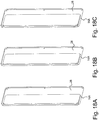
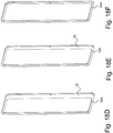
- at least part of the ring-spacers 16A, 16B may be provided with at least one separation wall 28 of variable height and length.
- Each separation wall 28 is configured for reducing the volume of the respective equalization chamber 14 and for covering at least part of the through holes 20A, 20B, 20C, 20D of the respective perforated plate 12A, 12B, 12C, 12D placed downstream of said separation wall 28.
- Different layouts of the ring-spacers 16A, 16B are thus possible.
- the ring-spacer 16A of figure 18A has a separation wall 28 that is designed to cover five columns of through holes 20A of the fully perforated plate 12A.
- the ring-spacer 16A of figure 18B has a separation wall 28 that is designed to cover four columns of through holes 20A of the fully perforated plate 12A.
- the ring-spacer 16A of figure 18C has a separation wall 28 that is designed to cover three columns of through holes 20A of the fully perforated plate 12A.
- the ring-spacer 16A of figure 18D has a separation wall 28 that is designed to cover two columns of through holes 20A of the fully perforated plate 12A.
- the ring-spacer 16A of figure 18E has a separation wall 28 that is designed to cover one column of through holes 20A of the fully perforated plate 12A.
- the ring-spacer 16A of figure 18F has no separation walls 28: all the through holes 20A of a perforated plate 12A placed downstream of said ring-spacer 16A are thus fully uncovered.
- At least part of the through holes 20A, 20B, 20C, 20D of one or more perforated plates 12A, 12B, 12C, 12D can have, instead of a cylindrical-shape as shown in figure 19 , a conical-shape section that widens in the flow direction A of the first fluid flowing into said through holes 20A, 20B, 20C, 20D.
- each of these through holes 20A, 20B, 20C, 20D forms a corresponding diverging conduit, as shown in figure 20 .
- Each diverging conduit can be obtained by punching or by laser machining for a single plate 12A, 12B, 12C, 12D.
- each diverging conduit can be obtained by coupling two or more perforated sheets 12C, 12D, 12E with the same number of through holes 20C, 20D, 20E, wherein the diameter of the holes 20C of a first perforated sheet 12C is smaller than the diameter of the corresponding through holes 20D, 20E of the subsequent perforated sheets 12D, 12E, with reference to the flow direction A of the first fluid flowing into said through holes 20C, 20D, 20E, as shown in figure 21 .
- the fluid distributor assembly for a heat exchanger of the present invention thus conceived is susceptible in any case of numerous modifications and variants, all falling within the same inventive concept; in addition, all the details can be substituted by technically equivalent elements.
- the materials used, as well as the shapes and size, can be of any type according to the technical requirements.
Landscapes
- Engineering & Computer Science (AREA)
- Physics & Mathematics (AREA)
- Thermal Sciences (AREA)
- Mechanical Engineering (AREA)
- General Engineering & Computer Science (AREA)
- Heat-Exchange Devices With Radiators And Conduit Assemblies (AREA)
Priority Applications (4)
| Application Number | Priority Date | Filing Date | Title |
|---|---|---|---|
| EP17425047.2A EP3399272B1 (fr) | 2017-05-04 | 2017-05-04 | Ensemble distributeur de fluide pour échangeurs de chaleur |
| CN201880029206.3A CN110770526B (zh) | 2017-05-04 | 2018-05-03 | 热交换器的流体分配器组件 |
| PCT/EP2018/061364 WO2018202781A1 (fr) | 2017-05-04 | 2018-05-03 | Ensemble distributeur de fluide pour échangeurs thermiques |
| US16/672,995 US11435147B2 (en) | 2017-05-04 | 2019-11-04 | Fluid distributor assembly for heat exchangers |
Applications Claiming Priority (1)
| Application Number | Priority Date | Filing Date | Title |
|---|---|---|---|
| EP17425047.2A EP3399272B1 (fr) | 2017-05-04 | 2017-05-04 | Ensemble distributeur de fluide pour échangeurs de chaleur |
Publications (2)
| Publication Number | Publication Date |
|---|---|
| EP3399272A1 true EP3399272A1 (fr) | 2018-11-07 |
| EP3399272B1 EP3399272B1 (fr) | 2020-02-26 |
Family
ID=59315562
Family Applications (1)
| Application Number | Title | Priority Date | Filing Date |
|---|---|---|---|
| EP17425047.2A Active EP3399272B1 (fr) | 2017-05-04 | 2017-05-04 | Ensemble distributeur de fluide pour échangeurs de chaleur |
Country Status (4)
| Country | Link |
|---|---|
| US (1) | US11435147B2 (fr) |
| EP (1) | EP3399272B1 (fr) |
| CN (1) | CN110770526B (fr) |
| WO (1) | WO2018202781A1 (fr) |
Cited By (1)
| Publication number | Priority date | Publication date | Assignee | Title |
|---|---|---|---|---|
| JP2021085535A (ja) * | 2019-11-25 | 2021-06-03 | ダイキン工業株式会社 | 熱交換器 |
Families Citing this family (8)
| Publication number | Priority date | Publication date | Assignee | Title |
|---|---|---|---|---|
| KR102139943B1 (ko) * | 2018-11-28 | 2020-08-03 | 조선대학교산학협력단 | 용접식 판형 열교환기 |
| CN113188350A (zh) * | 2020-09-07 | 2021-07-30 | 李辉 | 一种壳管式换热器 |
| US12416453B1 (en) * | 2021-07-22 | 2025-09-16 | Intergalactic Spaceworx, LLC | Heat exchange header with refrigerant distribution by capillary wicking porous insert |
| CN115046410B (zh) * | 2022-05-31 | 2025-10-24 | 艾恩科技集团(厦门)有限公司 | 一种热交换模块、系统以及热交换器 |
| WO2023238233A1 (fr) * | 2022-06-07 | 2023-12-14 | 三菱電機株式会社 | Échangeur de chaleur à calandre, et dispositif à cycle frigorifique |
| US12092376B2 (en) | 2022-07-19 | 2024-09-17 | King Fahd University Of Petroleum And Minerals | Absorption chiller refrigerator system |
| EP4715310A1 (fr) * | 2024-09-18 | 2026-03-25 | AIRBUS Operations GmbH | Conduit et plaque de base interne pour échangeur de chaleur, échangeur de chaleur, aéronef et procédé de vaporisation d'un fluide de travail associés |
| CN118960470B (zh) * | 2024-10-18 | 2025-01-24 | 浙江浙能航天氢能技术有限公司 | 一种流体自动分配的氢气冷却装置 |
Citations (8)
| Publication number | Priority date | Publication date | Assignee | Title |
|---|---|---|---|---|
| US2843367A (en) * | 1955-05-24 | 1958-07-15 | Young Radiator Co | Heat exchanger |
| US5419391A (en) * | 1991-04-05 | 1995-05-30 | Westinghouse Electric Corporation | Steam generator with axial flow preheater |
| WO2000055552A1 (fr) * | 1999-03-12 | 2000-09-21 | American Standard Inc. | Evaporateur a ruissellement dote d'un systeme de distribution de refrigerant a deux phases |
| JP2001241883A (ja) * | 2000-02-25 | 2001-09-07 | Nippon Shokubai Co Ltd | ガス分散板を設けた易重合性物質含有ガス用熱交換器およびその使用方法 |
| US6868695B1 (en) | 2004-04-13 | 2005-03-22 | American Standard International Inc. | Flow distributor and baffle system for a falling film evaporator |
| WO2012007344A2 (fr) * | 2010-07-16 | 2012-01-19 | Alfa Laval Corporate Ab | Dispositif d'échange de chaleur comportant un système perfectionné pour distribuer du fluide réfrigérant |
| CN102954628A (zh) | 2011-08-18 | 2013-03-06 | 浙江盾安人工环境股份有限公司 | 一种降膜式蒸发器用布液器 |
| US20140223936A1 (en) | 2011-09-26 | 2014-08-14 | Trane International Inc. | Refrigerant management in hvac systems |
Family Cites Families (4)
| Publication number | Priority date | Publication date | Assignee | Title |
|---|---|---|---|---|
| EP1079194B1 (fr) * | 1999-08-23 | 2004-01-21 | Nippon Shokubai Co., Ltd. | Méthode pour empêcher le blocage d'un échangeur de chaleur à plaques |
| JP4798655B2 (ja) * | 2005-12-21 | 2011-10-19 | 臼井国際産業株式会社 | 排気ガス冷却装置用多管式熱交換器 |
| CN103673726B (zh) * | 2012-09-05 | 2015-06-17 | 中国石油化工集团公司 | 共沸蒸馏换热器分配器 |
| CN204006813U (zh) * | 2014-08-21 | 2014-12-10 | 南京冷德节能科技有限公司 | 一种高效干式管壳式蒸发器 |
-
2017
- 2017-05-04 EP EP17425047.2A patent/EP3399272B1/fr active Active
-
2018
- 2018-05-03 CN CN201880029206.3A patent/CN110770526B/zh active Active
- 2018-05-03 WO PCT/EP2018/061364 patent/WO2018202781A1/fr not_active Ceased
-
2019
- 2019-11-04 US US16/672,995 patent/US11435147B2/en active Active
Patent Citations (9)
| Publication number | Priority date | Publication date | Assignee | Title |
|---|---|---|---|---|
| US2843367A (en) * | 1955-05-24 | 1958-07-15 | Young Radiator Co | Heat exchanger |
| US5419391A (en) * | 1991-04-05 | 1995-05-30 | Westinghouse Electric Corporation | Steam generator with axial flow preheater |
| WO2000055552A1 (fr) * | 1999-03-12 | 2000-09-21 | American Standard Inc. | Evaporateur a ruissellement dote d'un systeme de distribution de refrigerant a deux phases |
| JP2001241883A (ja) * | 2000-02-25 | 2001-09-07 | Nippon Shokubai Co Ltd | ガス分散板を設けた易重合性物質含有ガス用熱交換器およびその使用方法 |
| US6868695B1 (en) | 2004-04-13 | 2005-03-22 | American Standard International Inc. | Flow distributor and baffle system for a falling film evaporator |
| WO2012007344A2 (fr) * | 2010-07-16 | 2012-01-19 | Alfa Laval Corporate Ab | Dispositif d'échange de chaleur comportant un système perfectionné pour distribuer du fluide réfrigérant |
| US9310143B2 (en) | 2010-07-16 | 2016-04-12 | Alfa Laval Corporate Ab | Heat exchange device with improved system for distributing coolant fluid |
| CN102954628A (zh) | 2011-08-18 | 2013-03-06 | 浙江盾安人工环境股份有限公司 | 一种降膜式蒸发器用布液器 |
| US20140223936A1 (en) | 2011-09-26 | 2014-08-14 | Trane International Inc. | Refrigerant management in hvac systems |
Cited By (3)
| Publication number | Priority date | Publication date | Assignee | Title |
|---|---|---|---|---|
| JP2021085535A (ja) * | 2019-11-25 | 2021-06-03 | ダイキン工業株式会社 | 熱交換器 |
| EP4067800A4 (fr) * | 2019-11-25 | 2022-12-21 | Daikin Industries, Ltd. | Échangeur de chaleur |
| US12422201B2 (en) | 2019-11-25 | 2025-09-23 | Daikin Industries, Ltd. | Heat exchanger |
Also Published As
| Publication number | Publication date |
|---|---|
| CN110770526A (zh) | 2020-02-07 |
| WO2018202781A1 (fr) | 2018-11-08 |
| CN110770526B (zh) | 2021-07-23 |
| US20200064085A1 (en) | 2020-02-27 |
| US11435147B2 (en) | 2022-09-06 |
| EP3399272B1 (fr) | 2020-02-26 |
Similar Documents
| Publication | Publication Date | Title |
|---|---|---|
| US11435147B2 (en) | Fluid distributor assembly for heat exchangers | |
| US20230077459A1 (en) | Spiral tube heat exchanger | |
| KR101292362B1 (ko) | 플레이트 열교환기 | |
| US5540276A (en) | Finned tube heat exchanger and method of manufacture | |
| US8602089B2 (en) | Heat exchanger apparatus for accommodating thermal and/or pressure transients | |
| US20130264031A1 (en) | Heat exchanger with headering system and method for manufacturing same | |
| KR20130122537A (ko) | 다중 패스 관형 열교환기 및 연관된 패스 분할 판, 채널 커버, 및 방법 | |
| EP2594884B1 (fr) | Échangeur thermique à plaques et procédé de fabrication d'un échangeur thermique à plaques | |
| US20090183862A1 (en) | Heat exchanger and related exchange module | |
| KR20150126677A (ko) | 외피-및-관 열교환기용 관 번들 및 이용 방법 | |
| US20050167089A1 (en) | Multi-tube heat exchanger | |
| WO2014090102A1 (fr) | Échangeur de chaleur à plaques | |
| KR20150126676A (ko) | 외피-및-관 열교환기용 관 번들 및 그 구축 방법 | |
| CN106796088B (zh) | 多端口挤出式热交换器 | |
| US20150000133A1 (en) | Method for fabricating flattened tube finned heat exchanger | |
| US20160282062A1 (en) | Device for a heat exchanger for collecting and distributing a heat transfer fluid | |
| KR20140009220A (ko) | 플레이트형 열 교환기와 플레이트형 열 교환기를 제조하는 방법 | |
| CN115698621A (zh) | 热交换器 | |
| CA2969595C (fr) | Echangeur thermique a plaque spiralee ameliore | |
| RU2018130352A (ru) | Внутренние элементы в спирально закрученном теплообменнике для подавления газовых вихрей | |
| FI130318B (en) | Tube bundle heat exchanger | |
| CN105605962B (zh) | 制冷剂分配组件和换热器 | |
| US5894883A (en) | Shell and tube heat exchanger | |
| EP1995545B1 (fr) | Appareil à plaques pour processus de transmission thermique | |
| ITMI972380A1 (it) | Scambiatore di calore |
Legal Events
| Date | Code | Title | Description |
|---|---|---|---|
| PUAI | Public reference made under article 153(3) epc to a published international application that has entered the european phase |
Free format text: ORIGINAL CODE: 0009012 |
|
| STAA | Information on the status of an ep patent application or granted ep patent |
Free format text: STATUS: THE APPLICATION HAS BEEN PUBLISHED |
|
| AK | Designated contracting states |
Kind code of ref document: A1 Designated state(s): AL AT BE BG CH CY CZ DE DK EE ES FI FR GB GR HR HU IE IS IT LI LT LU LV MC MK MT NL NO PL PT RO RS SE SI SK SM TR |
|
| AX | Request for extension of the european patent |
Extension state: BA ME |
|
| STAA | Information on the status of an ep patent application or granted ep patent |
Free format text: STATUS: REQUEST FOR EXAMINATION WAS MADE |
|
| 17P | Request for examination filed |
Effective date: 20190502 |
|
| RBV | Designated contracting states (corrected) |
Designated state(s): AL AT BE BG CH CY CZ DE DK EE ES FI FR GB GR HR HU IE IS IT LI LT LU LV MC MK MT NL NO PL PT RO RS SE SI SK SM TR |
|
| RIC1 | Information provided on ipc code assigned before grant |
Ipc: F28F 9/02 20060101AFI20190522BHEP Ipc: F28D 7/16 20060101ALI20190522BHEP |
|
| GRAP | Despatch of communication of intention to grant a patent |
Free format text: ORIGINAL CODE: EPIDOSNIGR1 |
|
| STAA | Information on the status of an ep patent application or granted ep patent |
Free format text: STATUS: GRANT OF PATENT IS INTENDED |
|
| INTG | Intention to grant announced |
Effective date: 20190729 |
|
| RAP1 | Party data changed (applicant data changed or rights of an application transferred) |
Owner name: BITZER KUEHLMASCHINENBAU GMBH |
|
| GRAS | Grant fee paid |
Free format text: ORIGINAL CODE: EPIDOSNIGR3 |
|
| GRAJ | Information related to disapproval of communication of intention to grant by the applicant or resumption of examination proceedings by the epo deleted |
Free format text: ORIGINAL CODE: EPIDOSDIGR1 |
|
| GRAL | Information related to payment of fee for publishing/printing deleted |
Free format text: ORIGINAL CODE: EPIDOSDIGR3 |
|
| STAA | Information on the status of an ep patent application or granted ep patent |
Free format text: STATUS: REQUEST FOR EXAMINATION WAS MADE |
|
| GRAP | Despatch of communication of intention to grant a patent |
Free format text: ORIGINAL CODE: EPIDOSNIGR1 |
|
| STAA | Information on the status of an ep patent application or granted ep patent |
Free format text: STATUS: GRANT OF PATENT IS INTENDED |
|
| INTC | Intention to grant announced (deleted) | ||
| INTG | Intention to grant announced |
Effective date: 20191209 |
|
| GRAA | (expected) grant |
Free format text: ORIGINAL CODE: 0009210 |
|
| STAA | Information on the status of an ep patent application or granted ep patent |
Free format text: STATUS: THE PATENT HAS BEEN GRANTED |
|
| AK | Designated contracting states |
Kind code of ref document: B1 Designated state(s): AL AT BE BG CH CY CZ DE DK EE ES FI FR GB GR HR HU IE IS IT LI LT LU LV MC MK MT NL NO PL PT RO RS SE SI SK SM TR |
|
| REG | Reference to a national code |
Ref country code: GB Ref legal event code: FG4D |
|
| REG | Reference to a national code |
Ref country code: CH Ref legal event code: EP |
|
| REG | Reference to a national code |
Ref country code: AT Ref legal event code: REF Ref document number: 1238152 Country of ref document: AT Kind code of ref document: T Effective date: 20200315 |
|
| REG | Reference to a national code |
Ref country code: IE Ref legal event code: FG4D |
|
| REG | Reference to a national code |
Ref country code: DE Ref legal event code: R096 Ref document number: 602017012252 Country of ref document: DE |
|
| PG25 | Lapsed in a contracting state [announced via postgrant information from national office to epo] |
Ref country code: NO Free format text: LAPSE BECAUSE OF FAILURE TO SUBMIT A TRANSLATION OF THE DESCRIPTION OR TO PAY THE FEE WITHIN THE PRESCRIBED TIME-LIMIT Effective date: 20200526 Ref country code: RS Free format text: LAPSE BECAUSE OF FAILURE TO SUBMIT A TRANSLATION OF THE DESCRIPTION OR TO PAY THE FEE WITHIN THE PRESCRIBED TIME-LIMIT Effective date: 20200226 Ref country code: FI Free format text: LAPSE BECAUSE OF FAILURE TO SUBMIT A TRANSLATION OF THE DESCRIPTION OR TO PAY THE FEE WITHIN THE PRESCRIBED TIME-LIMIT Effective date: 20200226 |
|
| REG | Reference to a national code |
Ref country code: NL Ref legal event code: MP Effective date: 20200226 |
|
| REG | Reference to a national code |
Ref country code: LT Ref legal event code: MG4D |
|
| PG25 | Lapsed in a contracting state [announced via postgrant information from national office to epo] |
Ref country code: BG Free format text: LAPSE BECAUSE OF FAILURE TO SUBMIT A TRANSLATION OF THE DESCRIPTION OR TO PAY THE FEE WITHIN THE PRESCRIBED TIME-LIMIT Effective date: 20200526 Ref country code: GR Free format text: LAPSE BECAUSE OF FAILURE TO SUBMIT A TRANSLATION OF THE DESCRIPTION OR TO PAY THE FEE WITHIN THE PRESCRIBED TIME-LIMIT Effective date: 20200527 Ref country code: IS Free format text: LAPSE BECAUSE OF FAILURE TO SUBMIT A TRANSLATION OF THE DESCRIPTION OR TO PAY THE FEE WITHIN THE PRESCRIBED TIME-LIMIT Effective date: 20200626 Ref country code: LV Free format text: LAPSE BECAUSE OF FAILURE TO SUBMIT A TRANSLATION OF THE DESCRIPTION OR TO PAY THE FEE WITHIN THE PRESCRIBED TIME-LIMIT Effective date: 20200226 Ref country code: SE Free format text: LAPSE BECAUSE OF FAILURE TO SUBMIT A TRANSLATION OF THE DESCRIPTION OR TO PAY THE FEE WITHIN THE PRESCRIBED TIME-LIMIT Effective date: 20200226 Ref country code: HR Free format text: LAPSE BECAUSE OF FAILURE TO SUBMIT A TRANSLATION OF THE DESCRIPTION OR TO PAY THE FEE WITHIN THE PRESCRIBED TIME-LIMIT Effective date: 20200226 |
|
| PG25 | Lapsed in a contracting state [announced via postgrant information from national office to epo] |
Ref country code: NL Free format text: LAPSE BECAUSE OF FAILURE TO SUBMIT A TRANSLATION OF THE DESCRIPTION OR TO PAY THE FEE WITHIN THE PRESCRIBED TIME-LIMIT Effective date: 20200226 |
|
| PG25 | Lapsed in a contracting state [announced via postgrant information from national office to epo] |
Ref country code: PT Free format text: LAPSE BECAUSE OF FAILURE TO SUBMIT A TRANSLATION OF THE DESCRIPTION OR TO PAY THE FEE WITHIN THE PRESCRIBED TIME-LIMIT Effective date: 20200719 Ref country code: ES Free format text: LAPSE BECAUSE OF FAILURE TO SUBMIT A TRANSLATION OF THE DESCRIPTION OR TO PAY THE FEE WITHIN THE PRESCRIBED TIME-LIMIT Effective date: 20200226 Ref country code: SK Free format text: LAPSE BECAUSE OF FAILURE TO SUBMIT A TRANSLATION OF THE DESCRIPTION OR TO PAY THE FEE WITHIN THE PRESCRIBED TIME-LIMIT Effective date: 20200226 Ref country code: SM Free format text: LAPSE BECAUSE OF FAILURE TO SUBMIT A TRANSLATION OF THE DESCRIPTION OR TO PAY THE FEE WITHIN THE PRESCRIBED TIME-LIMIT Effective date: 20200226 Ref country code: LT Free format text: LAPSE BECAUSE OF FAILURE TO SUBMIT A TRANSLATION OF THE DESCRIPTION OR TO PAY THE FEE WITHIN THE PRESCRIBED TIME-LIMIT Effective date: 20200226 Ref country code: DK Free format text: LAPSE BECAUSE OF FAILURE TO SUBMIT A TRANSLATION OF THE DESCRIPTION OR TO PAY THE FEE WITHIN THE PRESCRIBED TIME-LIMIT Effective date: 20200226 Ref country code: RO Free format text: LAPSE BECAUSE OF FAILURE TO SUBMIT A TRANSLATION OF THE DESCRIPTION OR TO PAY THE FEE WITHIN THE PRESCRIBED TIME-LIMIT Effective date: 20200226 Ref country code: CZ Free format text: LAPSE BECAUSE OF FAILURE TO SUBMIT A TRANSLATION OF THE DESCRIPTION OR TO PAY THE FEE WITHIN THE PRESCRIBED TIME-LIMIT Effective date: 20200226 Ref country code: EE Free format text: LAPSE BECAUSE OF FAILURE TO SUBMIT A TRANSLATION OF THE DESCRIPTION OR TO PAY THE FEE WITHIN THE PRESCRIBED TIME-LIMIT Effective date: 20200226 |
|
| REG | Reference to a national code |
Ref country code: AT Ref legal event code: MK05 Ref document number: 1238152 Country of ref document: AT Kind code of ref document: T Effective date: 20200226 |
|
| REG | Reference to a national code |
Ref country code: DE Ref legal event code: R097 Ref document number: 602017012252 Country of ref document: DE |
|
| PLBE | No opposition filed within time limit |
Free format text: ORIGINAL CODE: 0009261 |
|
| STAA | Information on the status of an ep patent application or granted ep patent |
Free format text: STATUS: NO OPPOSITION FILED WITHIN TIME LIMIT |
|
| PG25 | Lapsed in a contracting state [announced via postgrant information from national office to epo] |
Ref country code: MC Free format text: LAPSE BECAUSE OF FAILURE TO SUBMIT A TRANSLATION OF THE DESCRIPTION OR TO PAY THE FEE WITHIN THE PRESCRIBED TIME-LIMIT Effective date: 20200226 Ref country code: CH Free format text: LAPSE BECAUSE OF NON-PAYMENT OF DUE FEES Effective date: 20200531 Ref country code: AT Free format text: LAPSE BECAUSE OF FAILURE TO SUBMIT A TRANSLATION OF THE DESCRIPTION OR TO PAY THE FEE WITHIN THE PRESCRIBED TIME-LIMIT Effective date: 20200226 Ref country code: LI Free format text: LAPSE BECAUSE OF NON-PAYMENT OF DUE FEES Effective date: 20200531 |
|
| 26N | No opposition filed |
Effective date: 20201127 |
|
| PG25 | Lapsed in a contracting state [announced via postgrant information from national office to epo] |
Ref country code: PL Free format text: LAPSE BECAUSE OF FAILURE TO SUBMIT A TRANSLATION OF THE DESCRIPTION OR TO PAY THE FEE WITHIN THE PRESCRIBED TIME-LIMIT Effective date: 20200226 Ref country code: SI Free format text: LAPSE BECAUSE OF FAILURE TO SUBMIT A TRANSLATION OF THE DESCRIPTION OR TO PAY THE FEE WITHIN THE PRESCRIBED TIME-LIMIT Effective date: 20200226 |
|
| REG | Reference to a national code |
Ref country code: BE Ref legal event code: MM Effective date: 20200531 |
|
| PG25 | Lapsed in a contracting state [announced via postgrant information from national office to epo] |
Ref country code: LU Free format text: LAPSE BECAUSE OF NON-PAYMENT OF DUE FEES Effective date: 20200504 |
|
| PG25 | Lapsed in a contracting state [announced via postgrant information from national office to epo] |
Ref country code: IE Free format text: LAPSE BECAUSE OF NON-PAYMENT OF DUE FEES Effective date: 20200504 |
|
| PG25 | Lapsed in a contracting state [announced via postgrant information from national office to epo] |
Ref country code: BE Free format text: LAPSE BECAUSE OF NON-PAYMENT OF DUE FEES Effective date: 20200531 |
|
| PG25 | Lapsed in a contracting state [announced via postgrant information from national office to epo] |
Ref country code: MT Free format text: LAPSE BECAUSE OF FAILURE TO SUBMIT A TRANSLATION OF THE DESCRIPTION OR TO PAY THE FEE WITHIN THE PRESCRIBED TIME-LIMIT Effective date: 20200226 Ref country code: CY Free format text: LAPSE BECAUSE OF FAILURE TO SUBMIT A TRANSLATION OF THE DESCRIPTION OR TO PAY THE FEE WITHIN THE PRESCRIBED TIME-LIMIT Effective date: 20200226 |
|
| PG25 | Lapsed in a contracting state [announced via postgrant information from national office to epo] |
Ref country code: MK Free format text: LAPSE BECAUSE OF FAILURE TO SUBMIT A TRANSLATION OF THE DESCRIPTION OR TO PAY THE FEE WITHIN THE PRESCRIBED TIME-LIMIT Effective date: 20200226 Ref country code: AL Free format text: LAPSE BECAUSE OF FAILURE TO SUBMIT A TRANSLATION OF THE DESCRIPTION OR TO PAY THE FEE WITHIN THE PRESCRIBED TIME-LIMIT Effective date: 20200226 |
|
| P01 | Opt-out of the competence of the unified patent court (upc) registered |
Effective date: 20230517 |
|
| PGFP | Annual fee paid to national office [announced via postgrant information from national office to epo] |
Ref country code: DE Payment date: 20250528 Year of fee payment: 9 |
|
| PGFP | Annual fee paid to national office [announced via postgrant information from national office to epo] |
Ref country code: IT Payment date: 20250522 Year of fee payment: 9 |
|
| PGFP | Annual fee paid to national office [announced via postgrant information from national office to epo] |
Ref country code: FR Payment date: 20250526 Year of fee payment: 9 |
|
| PGFP | Annual fee paid to national office [announced via postgrant information from national office to epo] |
Ref country code: TR Payment date: 20250416 Year of fee payment: 9 |
|
| PGFP | Annual fee paid to national office [announced via postgrant information from national office to epo] |
Ref country code: GB Payment date: 20260304 Year of fee payment: 10 |