EP3399332A1 - Système et procédé de détection d'imagerie tridimensionnelle holographique à ondes millimétriques - Google Patents
Système et procédé de détection d'imagerie tridimensionnelle holographique à ondes millimétriques Download PDFInfo
- Publication number
- EP3399332A1 EP3399332A1 EP16880275.9A EP16880275A EP3399332A1 EP 3399332 A1 EP3399332 A1 EP 3399332A1 EP 16880275 A EP16880275 A EP 16880275A EP 3399332 A1 EP3399332 A1 EP 3399332A1
- Authority
- EP
- European Patent Office
- Prior art keywords
- millimeter wave
- signal
- frequency
- port
- detected
- Prior art date
- Legal status (The legal status is an assumption and is not a legal conclusion. Google has not performed a legal analysis and makes no representation as to the accuracy of the status listed.)
- Withdrawn
Links
Images


Classifications
-
- G—PHYSICS
- G01—MEASURING; TESTING
- G01S—RADIO DIRECTION-FINDING; RADIO NAVIGATION; DETERMINING DISTANCE OR VELOCITY BY USE OF RADIO WAVES; LOCATING OR PRESENCE-DETECTING BY USE OF THE REFLECTION OR RERADIATION OF RADIO WAVES; ANALOGOUS ARRANGEMENTS USING OTHER WAVES
- G01S13/00—Systems using the reflection or reradiation of radio waves, e.g. radar systems; Analogous systems using reflection or reradiation of waves whose nature or wavelength is irrelevant or unspecified
- G01S13/88—Radar or analogous systems specially adapted for specific applications
- G01S13/89—Radar or analogous systems specially adapted for specific applications for mapping or imaging
- G01S13/90—Radar or analogous systems specially adapted for specific applications for mapping or imaging using synthetic aperture techniques, e.g. synthetic aperture radar [SAR] techniques
- G01S13/9004—SAR image acquisition techniques
- G01S13/9011—SAR image acquisition techniques with frequency domain processing of the SAR signals in azimuth
-
- G—PHYSICS
- G01—MEASURING; TESTING
- G01N—INVESTIGATING OR ANALYSING MATERIALS BY DETERMINING THEIR CHEMICAL OR PHYSICAL PROPERTIES
- G01N29/00—Investigating or analysing materials by the use of ultrasonic, sonic or infrasonic waves; Visualisation of the interior of objects by transmitting ultrasonic or sonic waves through the object
- G01N29/04—Analysing solids
- G01N29/06—Visualisation of the interior, e.g. acoustic microscopy
- G01N29/0654—Imaging
- G01N29/069—Defect imaging, localisation and sizing using, e.g. time of flight diffraction [TOFD], synthetic aperture focusing technique [SAFT], Amplituden-Laufzeit-Ortskurven [ALOK] technique
-
- G—PHYSICS
- G01—MEASURING; TESTING
- G01S—RADIO DIRECTION-FINDING; RADIO NAVIGATION; DETERMINING DISTANCE OR VELOCITY BY USE OF RADIO WAVES; LOCATING OR PRESENCE-DETECTING BY USE OF THE REFLECTION OR RERADIATION OF RADIO WAVES; ANALOGOUS ARRANGEMENTS USING OTHER WAVES
- G01S7/00—Details of systems according to groups G01S13/00, G01S15/00, G01S17/00
- G01S7/02—Details of systems according to groups G01S13/00, G01S15/00, G01S17/00 of systems according to group G01S13/00
- G01S7/35—Details of non-pulse systems
- G01S7/352—Receivers
- G01S7/356—Receivers involving particularities of FFT processing
-
- G—PHYSICS
- G01—MEASURING; TESTING
- G01S—RADIO DIRECTION-FINDING; RADIO NAVIGATION; DETERMINING DISTANCE OR VELOCITY BY USE OF RADIO WAVES; LOCATING OR PRESENCE-DETECTING BY USE OF THE REFLECTION OR RERADIATION OF RADIO WAVES; ANALOGOUS ARRANGEMENTS USING OTHER WAVES
- G01S13/00—Systems using the reflection or reradiation of radio waves, e.g. radar systems; Analogous systems using reflection or reradiation of waves whose nature or wavelength is irrelevant or unspecified
- G01S13/88—Radar or analogous systems specially adapted for specific applications
- G01S13/89—Radar or analogous systems specially adapted for specific applications for mapping or imaging
-
- G—PHYSICS
- G01—MEASURING; TESTING
- G01S—RADIO DIRECTION-FINDING; RADIO NAVIGATION; DETERMINING DISTANCE OR VELOCITY BY USE OF RADIO WAVES; LOCATING OR PRESENCE-DETECTING BY USE OF THE REFLECTION OR RERADIATION OF RADIO WAVES; ANALOGOUS ARRANGEMENTS USING OTHER WAVES
- G01S7/00—Details of systems according to groups G01S13/00, G01S15/00, G01S17/00
- G01S7/02—Details of systems according to groups G01S13/00, G01S15/00, G01S17/00 of systems according to group G01S13/00
- G01S7/35—Details of non-pulse systems
- G01S7/352—Receivers
-
- G—PHYSICS
- G01—MEASURING; TESTING
- G01V—GEOPHYSICS; GRAVITATIONAL MEASUREMENTS; DETECTING MASSES OR OBJECTS; TAGS
- G01V3/00—Electric or magnetic prospecting or detecting; Measuring magnetic field characteristics of the earth, e.g. declination, deviation
- G01V3/12—Electric or magnetic prospecting or detecting; Measuring magnetic field characteristics of the earth, e.g. declination, deviation operating with electromagnetic waves
-
- G—PHYSICS
- G01—MEASURING; TESTING
- G01V—GEOPHYSICS; GRAVITATIONAL MEASUREMENTS; DETECTING MASSES OR OBJECTS; TAGS
- G01V9/00—Prospecting or detecting by methods not provided for in groups G01V1/00 - G01V8/00
-
- G—PHYSICS
- G01—MEASURING; TESTING
- G01N—INVESTIGATING OR ANALYSING MATERIALS BY DETERMINING THEIR CHEMICAL OR PHYSICAL PROPERTIES
- G01N2291/00—Indexing codes associated with group G01N29/00
- G01N2291/02—Indexing codes associated with the analysed material
- G01N2291/023—Solids
-
- G—PHYSICS
- G01—MEASURING; TESTING
- G01S—RADIO DIRECTION-FINDING; RADIO NAVIGATION; DETERMINING DISTANCE OR VELOCITY BY USE OF RADIO WAVES; LOCATING OR PRESENCE-DETECTING BY USE OF THE REFLECTION OR RERADIATION OF RADIO WAVES; ANALOGOUS ARRANGEMENTS USING OTHER WAVES
- G01S13/00—Systems using the reflection or reradiation of radio waves, e.g. radar systems; Analogous systems using reflection or reradiation of waves whose nature or wavelength is irrelevant or unspecified
- G01S13/02—Systems using reflection of radio waves, e.g. primary radar systems; Analogous systems
- G01S13/06—Systems determining position data of a target
- G01S13/42—Simultaneous measurement of distance and other co-ordinates
- G01S13/426—Scanning radar, e.g. 3D radar
-
- G—PHYSICS
- G01—MEASURING; TESTING
- G01S—RADIO DIRECTION-FINDING; RADIO NAVIGATION; DETERMINING DISTANCE OR VELOCITY BY USE OF RADIO WAVES; LOCATING OR PRESENCE-DETECTING BY USE OF THE REFLECTION OR RERADIATION OF RADIO WAVES; ANALOGOUS ARRANGEMENTS USING OTHER WAVES
- G01S13/00—Systems using the reflection or reradiation of radio waves, e.g. radar systems; Analogous systems using reflection or reradiation of waves whose nature or wavelength is irrelevant or unspecified
- G01S13/88—Radar or analogous systems specially adapted for specific applications
- G01S13/887—Radar or analogous systems specially adapted for specific applications for detection of concealed objects, e.g. contraband or weapons
-
- G—PHYSICS
- G01—MEASURING; TESTING
- G01S—RADIO DIRECTION-FINDING; RADIO NAVIGATION; DETERMINING DISTANCE OR VELOCITY BY USE OF RADIO WAVES; LOCATING OR PRESENCE-DETECTING BY USE OF THE REFLECTION OR RERADIATION OF RADIO WAVES; ANALOGOUS ARRANGEMENTS USING OTHER WAVES
- G01S13/00—Systems using the reflection or reradiation of radio waves, e.g. radar systems; Analogous systems using reflection or reradiation of waves whose nature or wavelength is irrelevant or unspecified
- G01S13/88—Radar or analogous systems specially adapted for specific applications
- G01S13/89—Radar or analogous systems specially adapted for specific applications for mapping or imaging
- G01S13/90—Radar or analogous systems specially adapted for specific applications for mapping or imaging using synthetic aperture techniques, e.g. synthetic aperture radar [SAR] techniques
Definitions
- aspects of the present disclosure relate to a system and a method for millimeter wave holographic 3D imaging detection, and more particularly, to a system and a method based on the linear frequency modulation, superheterodyne detection principle and holographic imaging principle.
- the frequency of millimeter wave is between 30GHz to 300GHz (the wavelength is between 1mm to 10mm). In practical engineering applications, the low end frequency of millimeter wave is usually lowered to 26GHz.
- the frequency of millimeter wave is between microwave and infrared wave. Compared with microwave, the characteristics of millimeter wave are short wave length, wide bandwidth (with broad space for usage) and propagation characteristics in the air. Compared with infrared wave, millimeter wave has the capability of all-weather operations and can be applied in harsh conditions, such as smoke and mist. Under the circumstance that the frequency band of microwave is more and more crowded, millimeter wave has the merits of microwave and also has some merits that low-frequency band microwave lacks.
- millimeter wave has the following characteristics: 1. high precision, millimeter wave radar gets narrow wave beam and wide absolute bandwidth more easily, so that millimeter wave radar system has better anti-electronic interference capability; 2. among Doppler radars, millimeter wave's Doppler frequency has a high resolution; 3. in a millimeter wave imaging system, millimeter wave is sensitive to the shape and the structure of an object, can easily distinguish a metal object from background environment, and the obtained image has a high resolution, so as to enhance the capability of object identification and detection; 4. millimeter wave can penetrate plasma; 5. compared with infrared wave, millimeter wave is less influenced by harsh condition; 6. a millimeter wave system has small volume and light weight.
- the size of a millimeter wave circuit is much smaller and the millimeter wave system is easier to be integrated. It is these characteristics that bring millimeter wave technology wide application prospects, especially in the fields of nondestructive testing and security check.
- a millimeter wave imaging system uses single-channel mechanical scanning mechanism. Such imaging mechanism is simple in structure but needs a long scanning time.
- Millivision corporation has developed a Vetal125 imager. Except a transmission scanning system, this imager also comprises an 8*8 array receive mechanism. However, such imager is more suitable for outdoor wide-range remote monitoring, and its field of view is less than 50cm.
- Trex corporation has developed a PMC-2 imaging system.
- the antenna unit of this imaging system adopts 3mm phased-array antenna technology.
- the PMC-2 imaging system adopts a millimeter wave with central frequency of 84 GHz. Since the working frequency of such imaging system is close to the terahertz frequency band, the cost is high.
- Lockheed Martin corporation also has developed a focal plane array imaging system, and the center frequency of the millimeter wave adopted by this system is 94 GHz.
- TRW corporation has developed a passive millimeter wave imaging system, and the center frequency of the millimeter wave adopted by this system is 89 GHz.
- the field of view of the imaging systems of Lockheed Martin and TRW corporations is small, usually less than 50cm.
- the objective of this invention is to provide a millimeter wave holographic 3D imaging detection system with simple structure, high resolution and short imaging time.
- a millimeter wave holographic 3D imaging detection system comprises: a transmitting antenna configured to transmit a millimeter wave transmitting signal to an object to be detected; a receiving antenna configured to receive an echo signal from the object to be detected; a millimeter wave transceiving module configured to generate the millimeter wave transmitting signal transmitted to the object to be detected and receive and process the echo signal from the receiving antenna; a scanning device configured to support the millimeter wave transceiving module, the transmitting antenna and the receiving antenna, and move the millimeter transceiving module, the transmitting antenna and the receiving antenna along a preset track, so as to scan the object to be detected with millimeter waves; a data gathering and processing module configured to gather and process the echo signal output from the millimeter wave transceiving module to generate a 3D image of the object to be detected; and an image display unit configured to display the 3D image generated by the data gathering and processing module.
- a millimeter wave transceiving unit comprises one millimeter wave transceiving module, one transmitting antenna, and one receiving antenna; the direction of the transmitting antenna in the millimeter wave transceiving unit is the same as that of the receiving antenna; N millimeter wave transceiving units are arranged along the same direction to form a row of millimeter wave transceiving systems, wherein N is an integer greater than or equal to 2.
- the scanning device comprises: two flat surface detection panels, wherein each is used to support the row of millimeter wave transceiving system, and the two rows of millimeter wave transceiving systems in the two flat surface detection panels have opposite directions; two pairs of guideways, which are respectively placed on two sides of each flat surface detection panel, and each pair of guideways cooperate with each other to limit the row of millimeter wave transceiving system supported by corresponding flat surface detection panel to move along a preset track; and a motor, which is used to drive the row of millimeter wave transceiving system to move along the track of the corresponding guideway.
- N millimeter wave transceiving modules, N transmitting antennas, and N receiving antennas are arranged on each flat surface detection plane. Each millimeter wave transceiving module corresponds to one transmitting antenna and one receiving antenna. N millimeter wave transceiving modules are arranged in parallel to form a row of millimeter wave transceiving systems, N transmitting antennas are arranged in parallel to form an array of transmitting antennas, and N receiving antennas are arranged in parallel to form an array of receiving antennas, wherein N is an integer greater than or equal to 2.
- the row of millimeter wave transceiving system is controlled according to time sequence, so that the N millimeter wave transceiving units transmit and receive one by one according to preset sequence.
- the millimeter wave transceiving module comprises:
- the transmitting link comprises: a first directional coupler, wherein the input port of the first directional coupler is connected to the first signal source, and the pass-through port of the first directional coupler is connected to a first power amplifier; the first power amplifier configured to amplify the power of the signal output by the first directional coupler to reach a safer input power range of a first frequency doubler; and the first frequency doubler configured to double the frequency of the signal output by the first power amplifier to a second frequency range and output the frequency-doubled signal to the transmitting antenna.
- the receiving link comprises: a second directional coupler, wherein the input port of the second directional coupler is connected to the second signal source; a first mixer, wherein the local oscillation port of the first mixer is connected to the pass-through port of the second directional coupler, and the radio-frequency port of the first mixer is connected to the coupling port of the first directional coupler to generate a difference frequency signal of the first signal source and the second signal source; a second power amplifier, wherein the input port of the second power amplifier is connected to the intermediate frequency port of the first mixer to receive the difference frequency signal, and the second power amplifier amplifies the power of the difference frequency signal to reach the safe input power range of a second frequency doubler; the second frequency doubler, wherein the input port of the second frequency doubler is connected to output of the second power amplifier to double the frequency of the signal output by the second power amplifier to a second frequency; a second mixer, wherein the local oscillation port of the second mixer is connected to the output port of the second frequency doubler, and the radio-frequency port of the
- the receiving link also comprises a low noise amplifier, wherein the input port of the low noise amplifier is connected to the intermediate frequency port of the third mixer to amplify the received second down-converted signal and output it to the data gathering and processing module.
- the first frequency range is 13.5GHz-16.5GHz
- the second frequency range is 27GHz-33GHz
- the first frequency is 35MHz
- the second frequency is 70MHz.
- a method of millimeter wave holographic 3D imaging detection on an object to be detected using the above system thereof is provided.
- a method of millimeter wave holographic 3D imaging detection on an object to be detected using the system thereof comprises the following steps: the scanning device moves the millimeter wave transceiving module, the transmitting antenna, and the receiving antenna to scan the object to be detected; the millimeter wave transceiving module generates a millimeter wave transmitting signal; the transmitting antenna transmits the millimeter wave transmitting signal generated by the millimeter wave transceiving module to the object to be detected; the receiving antenna receives an echo signal from the object to be detected and transmits the echo signal to the millimeter wave transceiving module; the millimeter wave transceiving module processes the echo signal and sends it to the data gathering and processing module; the data gathering and processing module processes the signal from the millimeter wave transceiving module to generate a 3D image of the object to be detected; and the image display unit displays the 3D image generated by the data gathering and processing module.
- the data gathering and processing module performs the following steps: gathering the echo signal from the millimeter wave transceiving module, associating the echo signal to a spatial location signal, and performing Fourier transform and inverse Fourier transform to obtain the 3D image.
- the technical solution of this invention simplifies the system structure, improves the resolution, shortens the imaging time, and has larger field of view.
- a millimeter wave imaging mechanism mainly comprises millimeter wave active imaging and millimeter wave passive imaging.
- the advantages of the passive millimeter wave imaging system are simple structure and low implementation cost, and the disadvantages are long imaging time and inferior imaging resolution.
- millimeter wave active imaging is getting more and more attention.
- active synthetic aperture imaging and active holographic imaging are main imaging mechanisms.
- the method of millimeter wave holographic imaging comes from the method of optical hologram.
- Millimeter wave holographic imaging mainly adopts electromagnetic wave coherence principle.
- a transmitter first transmits a millimeter wave signal with high stability.
- a receiver receives the transmitting signal from each point of an object and performs coherent processing an echo signal with a reference signal with high coherence to extract the amplitude and phase information of the echo signal, so as to obtain the emission characteristic of each point of the object.
- the object millimeter wave image in an environment can be obtained by data and image processing method.
- the millimeter wave image obtained by millimeter wave active holographic imaging has a good resolution.
- the millimeter wave active holographic imaging can greatly shorten imaging time when cooperating with mechanical scanning and realize engineering. Therefore, the millimeter holographic imaging is especially suitable for millimeter wave short range active imaging.
- FIG. 1 illustrates a block diagram of a millimeter wave holographic 3D imaging detection system according to this invention.
- FIG. 2 illustrates a structural diagram of the millimeter wave holographic 3D imaging detection system according to this invention.
- a millimeter wave holographic 3D imaging detection system of this invention comprises: a transmitting antenna 14 configured to transmit a signal to an object to be detected; a receiving antenna 15 configured to receive an echo signal from the object to be detect; a millimeter wave transceiving module 11 configured to generate a millimeter wave transmitting signal sending to an object to be detected, receive and process the echo signal from the receiving antenna 15; a scanning device 10 configured to support the millimeter wave transceiving module 11, the transmitting antenna 14 and the receiving antenna 15 and move the millimeter wave transceiving module 11, the transmitting antenna 14 and the receiving antenna 15 along a preset track, so as to scan the object to be detected by millimeter wave; a data gathering and processing module 12 configured to gather and process the echo signal output by the millimeter wave transceiving module 11 to generate a 3D image of the object to be detected; and a imaging display unit 13 configured to display the 3D image generated by the data gathering and processing module.
- the scanning device 10 comprises a vertical guideway 21, a motor (for example, a stepper motor) 22, a flat surface detection plane 23.
- the scanning device 10 comprises two flat surface detection planes 23 for supporting the millimeter wave transceiving module 11, the transmitting antenna 14 and the receiving antenna 15.
- the object to be detected 24 is placed between the two flat surface detection planes 23.
- Each pair of guideways cooperate with each other to limit the millimeter wave transceiving module 11, the transmitting antenna 14 and the receiving antenna 15 supported by corresponding flat surface detection plane to move up and down along the guideways 21.
- the scanning device 10 also comprises a control motor 22 beside the detection plane 23.
- the control motor 22 is used to control the millimeter wave transceiving module 11, the transmitting antenna 14 and the receiving antenna 15 to move up and down along the guideways 21, so as to scan the object to be detected 24 up and down.
- the two flat surface detection planes 23 are arranged in parallel.
- N millimeter wave transceiving modules 11, N transmitting antennas 14, and N receiving antennas 15 are arranged on each flat surface detection plane 23.
- Each millimeter wave transceiving module 11 corresponds to one transmitting antenna 14 and one receiving antenna 15.
- N millimeter wave transceiving modules are arranged in parallel to form a row of millimeter wave transceiving systems, N transmitting antennas 14 are arranged in parallel to form an array of transmitting antennas, and N receiving antennas 15 are arranged in parallel to form an array of receiving antennas, wherein N is an integer greater than or equal to 2.
- one millimeter wave transceiving module 11, one transmitting antenna 14, and one receiving antenna 15 constitute a millimeter wave transceiving unit.
- a transmitting antenna and a receiving antenna in a millimeter wave transceiving unit have the same direction and are placed in the same column of an antenna array.
- the N millimeter wave transceiving units are arranged in the same direction (e.g., in horizontal direction) to form a row of millimeter wave transceiving systems, wherein N is an integer greater than or equal to 2.
- the directions of a row of millimeter wave transceiving systems supported by the two flat surface detection panels 23 are opposite to each other. That is, the antenna array directions of a row of millimeter wave transceiving systems supported by the two flat surface detection panels 23 are opposite to each other.
- the location information of the two opposite surfaces of the object to be detected can be scanned by moving up and down the two rows of millimeter wave transceiving systems corresponding to the two flat surface detection panels 23, so as to provide data to the data gathering and processing module 12 for subsequent compositing a complete 3D image of the object to be detected.
- a row of millimeter wave transceiving systems are controlled according to time sequence, so that the N millimeter wave transceving units transmit and receive millimeter waves one by one according to preset order. That is, the N millimeter wave transceiving modules 11 are controlled by time sequence to transmit and receive millimeter waves one by one, so as to accomplish horizontal scanning to the object to be detected.
- the N millimeter wave transceiving modules 11 can be controlled by a single-pole multiple throw switch.
- any time sequence control device known in the art can be applied.
- the object to be detected can move to improve imaging speed.
- the number of the millimeter wave transceiving modules 11 and the corresponding transmitting antennas 14 and receiving antennas 15 in a row of millimeter wave transceiving systems can be set according to parameters such as the width of the flat surface detection panel 23 and the desired imaging speed, while the width of the flat surface detection panel 23 can be determined according to the size of the object to be detected 24.
- the distance between the flat surface detection panel 23 and the object to be detected 24 can be determined according to antenna parameter and other parameters.
- a row of millimeter wave transceiving systems may comprise 64 millimeter wave transceing modules 11 and 128 antennas, wherein 1-64 transmitting antennas constitute the transmitting antenna array 14 for radiating linear frequency modulation continuous waves generated by the 64 millimeter wave transceiving modules 11 to the object to be detected 24, and 65-128 receiving antennas constitute the receiving antenna array 15 for receiving signals reflected by the object to be detected and transmitting them to the 64 millimeter wave transceiving modules 11.
- Each transmitting antenna corresponds to one receiving antenna, and transmitting antenna 1, 2, 3, ..., 63, and 64 corresponds to receiving antenna 65, 66, 67, ..., 127, and 128 respectively.
- the 64 millimeter wave transceiving modules 11 do not work at the same time, but are controlled by for example two-layer single-pole multiple throw switches to transmit and receive one by one.
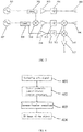
- FIG. 3 illustrates an electrical connection diagram of the millimeter wave transceiving module 11, the transmitting antenna 305, and the receiving antenna 306 in the millimiter wave holographic 3D imaging detection system according to this invention, wherein the millimeter wave transceiving module 11 comprises:
- the millimeter wave transceiving module 11 comprises: the transmitting link, which comprises the signal source 301, a directional coupler 302, a power amplifier 303, a frequency doubler 304, for generating a millimeter wave transmitting signal to the object to be detected 24; and the receiving link, which comprises the signal source 307, a directional coupler 309, mixers 310, 313, and 316, power amplifiers 311 and 314, frequency doublers 312 and 315, and a low noise amplifier 317, for receiving an echo signal from the object to be detected 24, processing the echo signal, and sending it to the data gathering and processing module 12.
- the transmitting link which comprises the signal source 301, a directional coupler 302, a power amplifier 303, a frequency doubler 304, for generating a millimeter wave transmitting signal to the object to be detected 24
- the receiving link which comprises the signal source 307, a directional coupler 309, mixers 310, 313, and 316, power amplifiers 311 and 314,
- S 1 t A 1 cos 2 ⁇ f 1 t + B 2 T t 2 + ⁇ 1
- a 1 is an initial amplitude
- ⁇ 1 is an initial scanning frequency of 13.5GHz
- ⁇ 1 is an initial phase of the signal source 301
- B is the bandwidth of a frequency modulation signal
- T is the frequency modulation duration.
- the frequency range of the signal source 301 and the frequency of the signal source 307 can be selected according to resolution requirement, which is common sense for persons skilled in the art and hence not described here.
- the directional coupler 302 is a three-port device, wherein the input port receives the output signal of the signal source 301, the pass-through port is connected to the power amplifier 303, so that the power of the transmitting link reaches safe input power range of the frequency doubler 304.
- the frequency of the transmitting link is doubled to a second frequency range (this frequency range is 27GHz-33GHz when the frequency range of the signal source 301 is 13.5GHz-16.5GHz), and finally radiated by a transmitting antenna to the object to be detected.
- the output signal of the second signal source 307 is connected to the input port of the directional coupler 309.
- the mixer 310 is a three-port device, wherein the local oscillation LO port is connected to the pass-through port of the directional coupler 309 to input an intermediate-frequency (e.g., 35MHz) signal, the radio frequency RF port is connected to the coupling port of the directional coupler 302 to input a frequency modulation (e.g., 13.5GHz-16.5GHz) signal, and the intermediate-frequency IF port outputs the difference frequency signal of the signals input by LO port and RF port to the power amplifier 311.
- the power amplifier 311 amplifies the power of the signal to the safe working range of the frequency doubler 312.
- the mixer 313 is a three-port device, wherein local oscillation LO port is connected to the output signal S(t) of the frequency doubler 312, the radio frequency RF port obtains the echo signal received by the receiving antenna 15 and reflected by the object to be detected.
- the two signal sources are noncoherent.
- a mixer 316 is introduced.
- this method eliminates the phase unsynchronization caused by the two nonconherent signal sources.
- the low noise amplifier 317 can amplify the weak intermediate frequency signal being down-converted twice to improve the output signal's signal-to-noise ratio and detection sensitivity. Its output signal is sent to the data gathering and processing module 12.
- the data gathering and processing module 12 processes the signal from the millimeter wave transceiving module 11 to generate a 3D image of the object to be detected, which comprises: gathering the echo signal from the millimeter wave transceiving module, associating the echo signal with the spatial location signal, and obtaining the 3D image by Fourier transform and inverse Fourier transform.
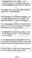
- FIG. 4 illustrates a flow diagram of a holographic 3D imaging algorithm performed by the data gathering and processing module of the millimeter wave holographic 3D imaging detection system according to this invention.
- the data gathering and processing module 12 first gathers the echo signal from the gathered signal (401), and then the echo signal is associating with the spatial location signal.
- a geometric characteristic Fourier transform is performed (402), then an inverse Fourier transform is performed after simplification and transformation (403), and finally the object's 3D image is obtained (404).
- the final data is obtained by taking the spatial domain location information into consideration.
- FIG. 5 illustrates a 3D object imaging schematic diagram of the millimeter wave holographic 3D imaging detection system according to this invention.
- a receiving antenna 501 of the position (X, Y, Z 0 ) receives the scattered broadband echo signal.
- the signal received by the antenna is sent to the millimeter wave circuit to be down-converted by the local oscillation signal with high coherence, and then is amplified by the low noise amplifier 317.
- the obtained signal is expressed as E(X, Y, ⁇ ), wherein ⁇ is the instantaneous angular frequency of the emission source.
- E(X, Y, ⁇ ) is the function of ⁇ , which can be expressed as follow: wherein ⁇ is the distance between the antenna and the object, K is the electromagnetic wave beam, the exponent part expresses a spherical signal scattered by the object and is important for object 3D scattering imaging. Furthermore,
- FIG. 6 illustrates a flow diagram of a millimeter wave holographic 3D imaging detection method according to this invention.
- the method of millimeter wave holographic 3D imaging detection on an object to be detected using the above system thereof comprises the following steps: a scanning device moves the millimeter wave transceiving module, the transmitting antenna, and the receiving antenna to scan the object to be detected; the millimeter wave transceiving module generates a millimeter wave transmitting signal; the transmitting antenna transmits the millimeter wave transmitting signal generated by the millimeter wave transceiving module to the object to be detected; the receiving antenna receives an echo signal from the object to be detected and transmits the echo signal to the millimeter wave transceiving module; the millimeter wave transceiving module processes the echo signal and sends it to the data gathering and processing module; the data gathering and processing module processes the signal from the millimeter wave transceiving module to generates the 3D image of the object to be detected; and the image display unit displays the 3D image generated by the data gathering and processing module.
- the millimeter wave holographic 3D imaging detection system and method according to this invention have the following advantages:
Landscapes
- Engineering & Computer Science (AREA)
- Remote Sensing (AREA)
- Physics & Mathematics (AREA)
- Radar, Positioning & Navigation (AREA)
- General Physics & Mathematics (AREA)
- Life Sciences & Earth Sciences (AREA)
- Computer Networks & Wireless Communication (AREA)
- Electromagnetism (AREA)
- Geophysics (AREA)
- General Life Sciences & Earth Sciences (AREA)
- Geology (AREA)
- Environmental & Geological Engineering (AREA)
- Signal Processing (AREA)
- Acoustics & Sound (AREA)
- Health & Medical Sciences (AREA)
- Chemical & Material Sciences (AREA)
- Analytical Chemistry (AREA)
- Biochemistry (AREA)
- General Health & Medical Sciences (AREA)
- Immunology (AREA)
- Pathology (AREA)
- Radar Systems Or Details Thereof (AREA)
Applications Claiming Priority (2)
| Application Number | Priority Date | Filing Date | Title |
|---|---|---|---|
| CN201511006075 | 2015-12-28 | ||
| PCT/CN2016/072411 WO2017113465A1 (fr) | 2015-12-28 | 2016-01-27 | Système et procédé de détection d'imagerie tridimensionnelle holographique à ondes millimétriques |
Publications (2)
| Publication Number | Publication Date |
|---|---|
| EP3399332A1 true EP3399332A1 (fr) | 2018-11-07 |
| EP3399332A4 EP3399332A4 (fr) | 2019-08-14 |
Family
ID=56229302
Family Applications (1)
| Application Number | Title | Priority Date | Filing Date |
|---|---|---|---|
| EP16880275.9A Withdrawn EP3399332A4 (fr) | 2015-12-28 | 2016-01-27 | Système et procédé de détection d'imagerie tridimensionnelle holographique à ondes millimétriques |
Country Status (4)
| Country | Link |
|---|---|
| US (1) | US11313963B2 (fr) |
| EP (1) | EP3399332A4 (fr) |
| CN (1) | CN105699494B (fr) |
| WO (1) | WO2017113465A1 (fr) |
Cited By (3)
| Publication number | Priority date | Publication date | Assignee | Title |
|---|---|---|---|---|
| CN110488294A (zh) * | 2019-09-09 | 2019-11-22 | 上海无线电设备研究所 | 一种星载多基线全息sar成像方法 |
| CN112099011A (zh) * | 2020-09-21 | 2020-12-18 | 中国科学院空天信息创新研究院 | 基于focuss算法的全息sar子孔径三维重建方法 |
| CN113960692A (zh) * | 2021-09-22 | 2022-01-21 | 北京金茂绿建科技有限公司 | 毫米波的感知方法、装置、电子设备和存储介质 |
Families Citing this family (34)
| Publication number | Priority date | Publication date | Assignee | Title |
|---|---|---|---|---|
| CN105699494B (zh) | 2015-12-28 | 2018-08-17 | 深圳市太赫兹科技创新研究院 | 毫米波全息三维成像检测系统和方法 |
| CN106405680B (zh) * | 2016-06-29 | 2019-09-17 | 深圳市无牙太赫兹科技有限公司 | 人体安检仪的监测方法和系统以及控制装置 |
| CN105938206B (zh) | 2016-07-06 | 2017-09-15 | 华讯方舟科技有限公司 | 毫米波安检仪调试系统及毫米波安检仪调试方法 |
| CN106094734B (zh) * | 2016-07-21 | 2019-01-01 | 华讯方舟科技有限公司 | 安检仪运动控制系统 |
| CN106338732B (zh) * | 2016-08-23 | 2019-02-26 | 华讯方舟科技有限公司 | 一种毫米波三维全息成像方法及系统 |
| CN106556874B (zh) * | 2016-10-31 | 2018-10-23 | 华讯方舟科技有限公司 | 一种近距离微波成像方法及系统 |
| CN108267734B (zh) * | 2016-12-30 | 2024-08-09 | 北京行易道科技有限公司 | 雷达 |
| CN108152821A (zh) * | 2018-01-23 | 2018-06-12 | 成都菲斯洛克电子技术有限公司 | 一种主动毫米波成像安全检测系统及安全检测方法 |
| CN210155349U (zh) * | 2018-03-09 | 2020-03-17 | 同方威视技术股份有限公司 | 可扩展式毫米波安检系统及扫描单元 |
| CN108519623A (zh) * | 2018-04-13 | 2018-09-11 | 北博(厦门)智能科技有限公司 | 基于毫米波雷达的异物探测系统 |
| CN109490980A (zh) * | 2018-12-28 | 2019-03-19 | 同方威视技术股份有限公司 | 毫米波安检门 |
| CN109917380B (zh) * | 2019-03-12 | 2022-12-06 | 西安电子工程研究所 | 一种通过功率检测实现综合孔径成像的方法 |
| US11715228B2 (en) | 2019-04-04 | 2023-08-01 | Battelle Memorial Institute | Imaging systems and related methods including radar imaging with moving arrays or moving targets |
| CN110632595B (zh) * | 2019-09-24 | 2022-11-01 | 西南交通大学 | 一种主动毫米波成像方法及系统、储存介质、成像设备 |
| EP4033967A4 (fr) * | 2019-09-29 | 2023-10-18 | Vayyar Imaging Ltd | Systèmes et procédés d'imagerie de surfaces cachées |
| CN110806589A (zh) * | 2019-11-15 | 2020-02-18 | 北京航天易联科技发展有限公司 | 一种近场实时成像系统和方法 |
| CN111142164B (zh) * | 2019-11-26 | 2022-07-05 | 内蒙古工业大学 | 一种柱面雷达成像系统 |
| CN111257960A (zh) * | 2019-12-17 | 2020-06-09 | 北京华航北斗能源科技有限公司 | 一种自动跟踪扫描快速通道式太赫兹安检设备 |
| CN111308462B (zh) * | 2019-12-19 | 2022-09-23 | 南京国微电子有限公司 | 一种毫米波探测通信一体化相控阵系统 |
| JP2021148620A (ja) * | 2020-03-19 | 2021-09-27 | 株式会社東芝 | アンテナ装置 |
| CN111624672A (zh) * | 2020-04-24 | 2020-09-04 | 博微太赫兹信息科技有限公司 | 一种基于频分复用技术的人体安检系统 |
| CN111638517B (zh) * | 2020-04-29 | 2022-01-11 | 八院云箭(北京)航天技术研究院有限公司 | 一种Ka波段机载高分辨率SAR系统 |
| CN112558064B (zh) * | 2020-09-30 | 2022-04-12 | 北京理工大学 | 一种基于可重构电磁表面阵列的三维成像系统 |
| CN112932488B (zh) * | 2021-01-26 | 2022-02-01 | 林和 | 一种智能化便携式教育仪 |
| WO2022219833A1 (fr) * | 2021-04-15 | 2022-10-20 | パナソニックIpマネジメント株式会社 | Dispositif d'imagerie |
| CN113093499B (zh) * | 2021-04-15 | 2022-03-01 | 中国地质大学(北京) | 一种离散孔径内推的太赫兹数字全息成像方法和系统 |
| CN113267465B (zh) * | 2021-05-13 | 2023-04-18 | 重庆邮电大学 | 一种基于时域光谱技术的太赫兹双模式成像系统及方法 |
| CN113281749B (zh) * | 2021-06-02 | 2023-05-23 | 西南交通大学 | 一种顾及同质性的时序InSAR高相干点选取方法 |
| CN113433210B (zh) * | 2021-06-24 | 2022-07-29 | 广东工业大学 | 一种无损检测的太赫兹线阵雷达扫描成像系统及方法 |
| CN113923618B (zh) * | 2021-10-11 | 2022-05-31 | 中国人民解放军国防科技大学 | 一种三维微波链路组网探测近地面三维降水实验场系统 |
| CN116520321B (zh) * | 2022-12-05 | 2024-07-19 | 重庆邮电大学 | 半波长均匀扫描的mimo阵列排布及其合成孔径成像方法 |
| CN116106974B (zh) * | 2022-12-08 | 2026-04-21 | 北京遥测技术研究所 | 一种无感知通过式实时安检方法 |
| CN119805380A (zh) * | 2025-02-27 | 2025-04-11 | 成都空间矩阵科技有限公司 | 一种低雷达可观测性反辐射模块 |
| CN120294390B (zh) * | 2025-04-09 | 2026-01-27 | 鼎新至测(北京)科技有限公司 | 一种新型全息无线电用电势测量装置及方法 |
Family Cites Families (18)
| Publication number | Priority date | Publication date | Assignee | Title |
|---|---|---|---|---|
| US5557283A (en) * | 1991-08-30 | 1996-09-17 | Sheen; David M. | Real-time wideband holographic surveillance system |
| US5455590A (en) * | 1991-08-30 | 1995-10-03 | Battelle Memorial Institute | Real-time holographic surveillance system |
| US7504993B2 (en) * | 2006-10-12 | 2009-03-17 | Agilent Technolgoies, Inc. | Coaxial bi-modal imaging system for combined microwave and optical imaging |
| DE102007045103A1 (de) | 2007-09-20 | 2009-04-02 | Loeffler Technology Gmbh | Verfahren und Vorrichtung zur synthetischen Bildgebung |
| SG184561A1 (en) | 2010-04-12 | 2012-11-29 | Maspro Denko Kk | Millimeter-wave image capturing device |
| CN102393537B (zh) * | 2011-10-30 | 2014-04-23 | 北京无线电计量测试研究所 | 一种人体安检系统利用频分技术的扫描方法 |
| CN102393536B (zh) * | 2011-10-30 | 2014-10-22 | 北京无线电计量测试研究所 | 一种人体安检系统利用频分空分技术的扫描方法 |
| CN102426361A (zh) * | 2011-10-30 | 2012-04-25 | 北京无线电计量测试研究所 | 一种毫米波主动式三维全息成像的人体安检系统 |
| CN102508306B (zh) * | 2011-10-30 | 2013-10-09 | 北京无线电计量测试研究所 | 一种利用空分技术的人体安检系统扫描方法 |
| CN102508240B (zh) * | 2011-10-30 | 2013-07-03 | 北京无线电计量测试研究所 | 毫米波主动式三维全息成像的人体安检系统的扫描方法 |
| CN102540185B (zh) * | 2011-12-30 | 2013-07-03 | 北京华航无线电测量研究所 | 一种阵列天线弧形扫描的毫米波成像系统成像的方法 |
| CN103869307A (zh) * | 2012-12-18 | 2014-06-18 | 中国农业科学院植物保护研究所 | 毫米波扫描昆虫雷达探测系统及探测方法 |
| CN104375143A (zh) * | 2013-08-15 | 2015-02-25 | 同方威视技术股份有限公司 | 毫米波三维全息扫描成像设备及人体或物品检查方法 |
| CN104375144A (zh) * | 2013-08-15 | 2015-02-25 | 同方威视技术股份有限公司 | 毫米波三维全息扫描成像设备及人体或物品检查方法 |
| CN104375141A (zh) * | 2013-08-15 | 2015-02-25 | 同方威视技术股份有限公司 | 毫米波三维全息扫描成像设备及检查方法 |
| EP2933654B1 (fr) | 2014-04-14 | 2017-06-07 | Rohde & Schwarz GmbH & Co. KG | Procédé et système de reconstruction d'image à ondes millimétriques |
| CN104991283A (zh) * | 2015-07-13 | 2015-10-21 | 深圳市一体太赫兹科技有限公司 | 一种面式毫米波扫描的三维全息成像安检系统 |
| CN105699494B (zh) * | 2015-12-28 | 2018-08-17 | 深圳市太赫兹科技创新研究院 | 毫米波全息三维成像检测系统和方法 |
-
2016
- 2016-01-22 CN CN201610046575.6A patent/CN105699494B/zh not_active Ceased
- 2016-01-27 US US16/066,629 patent/US11313963B2/en active Active
- 2016-01-27 EP EP16880275.9A patent/EP3399332A4/fr not_active Withdrawn
- 2016-01-27 WO PCT/CN2016/072411 patent/WO2017113465A1/fr not_active Ceased
Cited By (4)
| Publication number | Priority date | Publication date | Assignee | Title |
|---|---|---|---|---|
| CN110488294A (zh) * | 2019-09-09 | 2019-11-22 | 上海无线电设备研究所 | 一种星载多基线全息sar成像方法 |
| CN112099011A (zh) * | 2020-09-21 | 2020-12-18 | 中国科学院空天信息创新研究院 | 基于focuss算法的全息sar子孔径三维重建方法 |
| CN112099011B (zh) * | 2020-09-21 | 2022-05-17 | 中国科学院空天信息创新研究院 | 基于focuss算法的全息sar子孔径三维重建方法 |
| CN113960692A (zh) * | 2021-09-22 | 2022-01-21 | 北京金茂绿建科技有限公司 | 毫米波的感知方法、装置、电子设备和存储介质 |
Also Published As
| Publication number | Publication date |
|---|---|
| CN105699494B (zh) | 2018-08-17 |
| US20190004171A1 (en) | 2019-01-03 |
| WO2017113465A1 (fr) | 2017-07-06 |
| EP3399332A4 (fr) | 2019-08-14 |
| CN105699494A (zh) | 2016-06-22 |
| US11313963B2 (en) | 2022-04-26 |
Similar Documents
| Publication | Publication Date | Title |
|---|---|---|
| US11313963B2 (en) | Millimeter wave holographic three-dimensional imaging detection system and method | |
| US11500088B2 (en) | Millimeter-wave real-time imaging based safety inspection system and safety inspection method | |
| CN105607056A (zh) | 人体安检系统和方法 | |
| CN105699493B (zh) | 高铁无损检测系统和方法 | |
| CN105759269B (zh) | 三维全息成像的安检系统及方法 | |
| CN105572667B (zh) | 包裹安全检测系统和方法 | |
| CN105510911B (zh) | 基于线性调频的多人人体安检设备及方法 | |
| CN105606630B (zh) | 导弹外壳无损检测系统和方法 | |
| CN106291732B (zh) | 基于毫米波成像的全方位安检系统 | |
| EP3511745B1 (fr) | Procédé et appareil de réglage de puissance et dispositif de contrôle de sécurité de corps humain | |
| CN111103583B (zh) | 一种具有实时校准的三维射频成像系统和方法 | |
| CN207352187U (zh) | 毫米波实时成像安全检测系统 | |
| Baccouche et al. | A sparse array based sub-terahertz imaging system for volume inspection | |
| Yurduseven et al. | Point-spread-function (PSF) characterization of a 340-GHz imaging radar using acoustic levitation | |
| CN105629229B (zh) | 飞机无损检测系统和方法 | |
| JP5080795B2 (ja) | イメージング装置 | |
| CN210465676U (zh) | 一种毫米波宽角波束扫描雷达传感器 | |
| CN105629230B (zh) | 战地车无损检测系统和方法 | |
| CN105699968B (zh) | 舰船无损检测系统和方法 | |
| CN206020692U (zh) | 功率调节装置和人体安检设备 | |
| Yurduseven et al. | From microwaves to submillimeter waves: modern advances in computational imaging, radar, and future trends | |
| CN205450266U (zh) | 基于线性调频的多人人体安检设备 | |
| Monnai | Terahertz Radar Based on Leaky-Wave Coherence Tomography | |
| Taira et al. | Terahertz wave sensing technology for visualizing hidden objects | |
| Cui et al. | Comparison of terahertz transceiver array topologies in multiobject imaging |
Legal Events
| Date | Code | Title | Description |
|---|---|---|---|
| STAA | Information on the status of an ep patent application or granted ep patent |
Free format text: STATUS: THE INTERNATIONAL PUBLICATION HAS BEEN MADE |
|
| PUAI | Public reference made under article 153(3) epc to a published international application that has entered the european phase |
Free format text: ORIGINAL CODE: 0009012 |
|
| STAA | Information on the status of an ep patent application or granted ep patent |
Free format text: STATUS: REQUEST FOR EXAMINATION WAS MADE |
|
| 17P | Request for examination filed |
Effective date: 20180727 |
|
| AK | Designated contracting states |
Kind code of ref document: A1 Designated state(s): AL AT BE BG CH CY CZ DE DK EE ES FI FR GB GR HR HU IE IS IT LI LT LU LV MC MK MT NL NO PL PT RO RS SE SI SK SM TR |
|
| AX | Request for extension of the european patent |
Extension state: BA ME |
|
| DAV | Request for validation of the european patent (deleted) | ||
| DAX | Request for extension of the european patent (deleted) | ||
| A4 | Supplementary search report drawn up and despatched |
Effective date: 20190711 |
|
| RIC1 | Information provided on ipc code assigned before grant |
Ipc: G01S 13/89 20060101AFI20190705BHEP Ipc: G01V 9/00 20060101ALI20190705BHEP Ipc: G01V 3/12 20060101ALI20190705BHEP |
|
| STAA | Information on the status of an ep patent application or granted ep patent |
Free format text: STATUS: EXAMINATION IS IN PROGRESS |
|
| 17Q | First examination report despatched |
Effective date: 20210715 |
|
| STAA | Information on the status of an ep patent application or granted ep patent |
Free format text: STATUS: THE APPLICATION IS DEEMED TO BE WITHDRAWN |
|
| 18D | Application deemed to be withdrawn |
Effective date: 20240316 |