EP3399334B1 - Dispositif de détection d'objets et dispositif formant capteur - Google Patents
Dispositif de détection d'objets et dispositif formant capteur Download PDFInfo
- Publication number
- EP3399334B1 EP3399334B1 EP16890494.4A EP16890494A EP3399334B1 EP 3399334 B1 EP3399334 B1 EP 3399334B1 EP 16890494 A EP16890494 A EP 16890494A EP 3399334 B1 EP3399334 B1 EP 3399334B1
- Authority
- EP
- European Patent Office
- Prior art keywords
- frequency
- object detecting
- detecting device
- signal
- velocity
- Prior art date
- Legal status (The legal status is an assumption and is not a legal conclusion. Google has not performed a legal analysis and makes no representation as to the accuracy of the status listed.)
- Active
Links
Images




Classifications
-
- G—PHYSICS
- G01—MEASURING; TESTING
- G01S—RADIO DIRECTION-FINDING; RADIO NAVIGATION; DETERMINING DISTANCE OR VELOCITY BY USE OF RADIO WAVES; LOCATING OR PRESENCE-DETECTING BY USE OF THE REFLECTION OR RERADIATION OF RADIO WAVES; ANALOGOUS ARRANGEMENTS USING OTHER WAVES
- G01S17/00—Systems using the reflection or reradiation of electromagnetic waves other than radio waves, e.g. lidar systems
- G01S17/003—Bistatic lidar systems; Multistatic lidar systems
-
- G—PHYSICS
- G01—MEASURING; TESTING
- G01S—RADIO DIRECTION-FINDING; RADIO NAVIGATION; DETERMINING DISTANCE OR VELOCITY BY USE OF RADIO WAVES; LOCATING OR PRESENCE-DETECTING BY USE OF THE REFLECTION OR RERADIATION OF RADIO WAVES; ANALOGOUS ARRANGEMENTS USING OTHER WAVES
- G01S7/00—Details of systems according to groups G01S13/00, G01S15/00, G01S17/00
- G01S7/02—Details of systems according to groups G01S13/00, G01S15/00, G01S17/00 of systems according to group G01S13/00
- G01S7/35—Details of non-pulse systems
- G01S7/352—Receivers
-
- G—PHYSICS
- G01—MEASURING; TESTING
- G01S—RADIO DIRECTION-FINDING; RADIO NAVIGATION; DETERMINING DISTANCE OR VELOCITY BY USE OF RADIO WAVES; LOCATING OR PRESENCE-DETECTING BY USE OF THE REFLECTION OR RERADIATION OF RADIO WAVES; ANALOGOUS ARRANGEMENTS USING OTHER WAVES
- G01S13/00—Systems using the reflection or reradiation of radio waves, e.g. radar systems; Analogous systems using reflection or reradiation of waves whose nature or wavelength is irrelevant or unspecified
- G01S13/02—Systems using reflection of radio waves, e.g. primary radar systems; Analogous systems
- G01S13/06—Systems determining position data of a target
- G01S13/08—Systems for measuring distance only
- G01S13/32—Systems for measuring distance only using transmission of continuous waves, whether amplitude-, frequency-, or phase-modulated, or unmodulated
- G01S13/34—Systems for measuring distance only using transmission of continuous waves, whether amplitude-, frequency-, or phase-modulated, or unmodulated using transmission of continuous, frequency-modulated waves while heterodyning the received signal, or a signal derived therefrom, with a locally-generated signal related to the contemporaneously transmitted signal
-
- G—PHYSICS
- G01—MEASURING; TESTING
- G01S—RADIO DIRECTION-FINDING; RADIO NAVIGATION; DETERMINING DISTANCE OR VELOCITY BY USE OF RADIO WAVES; LOCATING OR PRESENCE-DETECTING BY USE OF THE REFLECTION OR RERADIATION OF RADIO WAVES; ANALOGOUS ARRANGEMENTS USING OTHER WAVES
- G01S13/00—Systems using the reflection or reradiation of radio waves, e.g. radar systems; Analogous systems using reflection or reradiation of waves whose nature or wavelength is irrelevant or unspecified
- G01S13/02—Systems using reflection of radio waves, e.g. primary radar systems; Analogous systems
- G01S13/06—Systems determining position data of a target
- G01S13/08—Systems for measuring distance only
- G01S13/32—Systems for measuring distance only using transmission of continuous waves, whether amplitude-, frequency-, or phase-modulated, or unmodulated
- G01S13/34—Systems for measuring distance only using transmission of continuous waves, whether amplitude-, frequency-, or phase-modulated, or unmodulated using transmission of continuous, frequency-modulated waves while heterodyning the received signal, or a signal derived therefrom, with a locally-generated signal related to the contemporaneously transmitted signal
- G01S13/345—Systems for measuring distance only using transmission of continuous waves, whether amplitude-, frequency-, or phase-modulated, or unmodulated using transmission of continuous, frequency-modulated waves while heterodyning the received signal, or a signal derived therefrom, with a locally-generated signal related to the contemporaneously transmitted signal using triangular modulation
-
- G—PHYSICS
- G01—MEASURING; TESTING
- G01S—RADIO DIRECTION-FINDING; RADIO NAVIGATION; DETERMINING DISTANCE OR VELOCITY BY USE OF RADIO WAVES; LOCATING OR PRESENCE-DETECTING BY USE OF THE REFLECTION OR RERADIATION OF RADIO WAVES; ANALOGOUS ARRANGEMENTS USING OTHER WAVES
- G01S13/00—Systems using the reflection or reradiation of radio waves, e.g. radar systems; Analogous systems using reflection or reradiation of waves whose nature or wavelength is irrelevant or unspecified
- G01S13/02—Systems using reflection of radio waves, e.g. primary radar systems; Analogous systems
- G01S13/50—Systems of measurement based on relative movement of target
- G01S13/58—Velocity or trajectory determination systems; Sense-of-movement determination systems
- G01S13/583—Velocity or trajectory determination systems; Sense-of-movement determination systems using transmission of continuous unmodulated waves, amplitude-, frequency-, or phase-modulated waves and based upon the Doppler effect resulting from movement of targets
-
- G—PHYSICS
- G01—MEASURING; TESTING
- G01S—RADIO DIRECTION-FINDING; RADIO NAVIGATION; DETERMINING DISTANCE OR VELOCITY BY USE OF RADIO WAVES; LOCATING OR PRESENCE-DETECTING BY USE OF THE REFLECTION OR RERADIATION OF RADIO WAVES; ANALOGOUS ARRANGEMENTS USING OTHER WAVES
- G01S13/00—Systems using the reflection or reradiation of radio waves, e.g. radar systems; Analogous systems using reflection or reradiation of waves whose nature or wavelength is irrelevant or unspecified
- G01S13/86—Combinations of radar systems with non-radar systems, e.g. sonar, direction finder
-
- G—PHYSICS
- G01—MEASURING; TESTING
- G01S—RADIO DIRECTION-FINDING; RADIO NAVIGATION; DETERMINING DISTANCE OR VELOCITY BY USE OF RADIO WAVES; LOCATING OR PRESENCE-DETECTING BY USE OF THE REFLECTION OR RERADIATION OF RADIO WAVES; ANALOGOUS ARRANGEMENTS USING OTHER WAVES
- G01S13/00—Systems using the reflection or reradiation of radio waves, e.g. radar systems; Analogous systems using reflection or reradiation of waves whose nature or wavelength is irrelevant or unspecified
- G01S13/87—Combinations of radar systems, e.g. primary radar and secondary radar
-
- G—PHYSICS
- G01—MEASURING; TESTING
- G01S—RADIO DIRECTION-FINDING; RADIO NAVIGATION; DETERMINING DISTANCE OR VELOCITY BY USE OF RADIO WAVES; LOCATING OR PRESENCE-DETECTING BY USE OF THE REFLECTION OR RERADIATION OF RADIO WAVES; ANALOGOUS ARRANGEMENTS USING OTHER WAVES
- G01S17/00—Systems using the reflection or reradiation of electromagnetic waves other than radio waves, e.g. lidar systems
- G01S17/02—Systems using the reflection of electromagnetic waves other than radio waves
- G01S17/06—Systems determining position data of a target
- G01S17/08—Systems determining position data of a target for measuring distance only
- G01S17/10—Systems determining position data of a target for measuring distance only using transmission of interrupted, pulse-modulated waves
- G01S17/26—Systems determining position data of a target for measuring distance only using transmission of interrupted, pulse-modulated waves wherein the transmitted pulses use a frequency-modulated or phase-modulated carrier wave, e.g. for pulse compression of received signals
-
- G—PHYSICS
- G01—MEASURING; TESTING
- G01S—RADIO DIRECTION-FINDING; RADIO NAVIGATION; DETERMINING DISTANCE OR VELOCITY BY USE OF RADIO WAVES; LOCATING OR PRESENCE-DETECTING BY USE OF THE REFLECTION OR RERADIATION OF RADIO WAVES; ANALOGOUS ARRANGEMENTS USING OTHER WAVES
- G01S7/00—Details of systems according to groups G01S13/00, G01S15/00, G01S17/00
- G01S7/48—Details of systems according to groups G01S13/00, G01S15/00, G01S17/00 of systems according to group G01S17/00
- G01S7/483—Details of pulse systems
- G01S7/486—Receivers
- G01S7/487—Extracting wanted echo signals, e.g. pulse detection
- G01S7/4873—Extracting wanted echo signals, e.g. pulse detection by deriving and controlling a threshold value
-
- G—PHYSICS
- G01—MEASURING; TESTING
- G01S—RADIO DIRECTION-FINDING; RADIO NAVIGATION; DETERMINING DISTANCE OR VELOCITY BY USE OF RADIO WAVES; LOCATING OR PRESENCE-DETECTING BY USE OF THE REFLECTION OR RERADIATION OF RADIO WAVES; ANALOGOUS ARRANGEMENTS USING OTHER WAVES
- G01S7/00—Details of systems according to groups G01S13/00, G01S15/00, G01S17/00
- G01S7/48—Details of systems according to groups G01S13/00, G01S15/00, G01S17/00 of systems according to group G01S17/00
- G01S7/497—Means for monitoring or calibrating
- G01S7/4972—Alignment of sensor
Definitions
- the present invention relates to an object detecting device for detecting an object existing in a space, and also relates to a sensor device mounting the object detecting device thereon.
- the following method is known as a method for enhancing a detection probability by an object detecting device for detecting an object existing in a space.
- a method is known as enhancing a detection probability of an object by receiving a signal reflecting off the object existing in the space with a plurality of object detecting devices, combining reception signals of the plurality of object detecting devices, and detecting the object from a combined signal, as compared with the case of detecting the object from a reception signal of a single object detecting device.
- a detection probability of an object to be detected is enhanced by acquiring position information of the object prior to combining reception signals of a plurality of object detecting devices, and performing coherent combining using the position information.
- Patent Literature 1 describes a radar system which includes an amplifier for amplifying the beat signal at an amplification factor varying with the frequency, and a level correcting device for correcting a spectrum level of an amplified signal or a spectrum level of a signal generated based on the amplified signal, into a spectrum level obtained when the beat signal is amplified without involving Doppler shift caused by a velocity of the target relative to the radar system.
- a level correcting device for correcting a spectrum level of an amplified signal or a spectrum level of a signal generated based on the amplified signal, into a spectrum level obtained when the beat signal is amplified without involving Doppler shift caused by a velocity of the target relative to the radar system.
- Patent Literature 2 a radar apparatus is described.
- any change detected in the characteristic of a receiver circuit is corrected during normal operation or at the time of an initial adjustment before shipment from factory and, furthermore, any change occurring in the characteristic due to aging or temperature variations in the operating environment is corrected as needed.
- Patent Literature 3 describes a radar which may be employed in anti-collision systems or cruise control systems installed in moving objects such as automotive vehicles.
- the radar produces a first spectrum using a portion of a beat signal in a frequency rising range wherein the frequency of the radar wave increases and a second spectrum using a portion of the beat signal in a frequency falling range wherein the frequency of the radar wave decreases and moves the second spectrum by frequency shifts which are determined as a function of the speed of a radar-mounted vehicle and corrected for compensating various errors involved in measuring the speed of the vehicle to form spectrum groups each consisting of the frequency components moved by one of the corrected frequency shifts and frequency components in the other of the first and second spectra.
- Non-Patent Literature 1 " Wideband Distributed Coherent Aperture Radar,” 2014 IEEE Radar Conference, pp. 1114-1117, May 2014 ;
- the detection probability of the object may be enhanced by acquiring in advance the position information of the object to be detected and performing the coherent combining using the position information.
- the detection probability of the object cannot be enhanced.
- the present invention has been made to solve the above problem, and an object thereof is to provide an object detecting device that is capable of enhancing a detection probability of an object to be detected without acquiring position information of the object in advance.
- An object detecting device is an object detecting device among a plurality of object detecting devices that detect an object, each of the object detecting devices is provided with: a transmission high-frequency circuit; a transmission signal generating circuit configured to output a transmission signal to the transmission high-frequency circuit; a beat signal extractor configured to receive a signal reflecting off an object to be detected and extract a beat signal from the received signal, wherein the beat signal extractor comprises a reception high-frequency circuit configured to perform a frequency conversion process of converting the frequency of the received signal to generate a reception signal and a beat signal extracting circuit configured to extract the beat signal from the reception signal by multiplying the reception signal and the transmission signal output from the transmission signal generating circuit together; a position and velocity information outputting device configured to detect a position and a velocity of the object detecting device and configured to output first position and velocity information indicating the position and the velocity of the object detecting device; a multiplexer configured to multiplex the extracted beat
- FIG. 1 is an explanatory diagram illustrating a relation between a plurality of object detecting devices and an object to be detected according to Embodiment 1 of the present invention.
- FIG. 1 illustrates an example using three object detecting devices 1a, 1b, and 1c, it is not limited to three as far as two or more object detecting devices are used.
- the object detecting device la radiates toward a space a transmission wave such as a radio frequency (RF) signal, and a reflected wave reflecting off and returning from an object 2 to be detected reaches the object detecting device 1a, the object detecting device 1b, and the object detecting device 1c.
- RF radio frequency
- the object detecting devices 1a, 1b, and 1c may be expressed as an object detecting device 1 when it is not needed to distinguish those devices from each other.
- FIG. 2 is a structural diagram illustrating a sensor device according to Embodiment 1 of the present invention, on which the object detecting device 1 is mounted.
- an object monitor 3 is a processor for performing a process of monitoring the object 2 detected by the object detecting device 1.
- a monitoring process for the object 2 performed by the object monitor 3 includes: a process of monitoring change in the position and velocity of the object 2 by recording a relative velocity v r and a distance Ri to the object 2 detected by the object detecting device 1, and; a prediction process of predicting a future position and a future velocity of the object 2. Since the prediction process for predicting the future position and velocity of the object is a known technique, a detailed explanation will be omitted here.
- the sensor device of FIG. 2 includes an object monitoring device such as a target tracking device or a radar device.
- Embodiment 1 an example will be described, in which the object detecting device 1 detects the object 2 by using a distance measurement system called a frequency modulation continuous wave (FMCW) system.
- FMCW frequency modulation continuous wave
- FIG. 3 is a structural diagram illustrating the object detecting device 1 according to Embodiment 1 of the present invention.
- a transmission signal generating circuit 11 is implemented by, for example, a combiner, an oscillator, a processor, a digital to analog converter (DAC), and the like.
- the transmission signal generating circuit 11 generates a transmission signal subjected to frequency modulation in which the frequency changes over time, and outputs the transmission signal to a transmission high-frequency circuit 12 and a beat signal extracting circuit 17.
- the processor may be, for example, a field-programmable gate array (FPGA), a Digital Signal Processor (DSP), a central processor (CPU), or the like.
- FPGA field-programmable gate array
- DSP Digital Signal Processor
- CPU central processor
- a filter for removing harmonics may be provided at the output side of the DAC.
- the transmission high-frequency circuit 12 performs: a frequency conversion process of converting a frequency of the transmission signal output from the transmission signal generating circuit 11 into a carrier frequency; a filter process of removing spurious emissions and out-of-band frequencies of the transmission signal; a power amplification process of amplifying power of the transmission signal; and the like.
- the transmission high-frequency circuit 12 outputs, as a transmission wave to a transmission antenna 13, the transmission signal obtained through the foregoing processes.
- the transmission antenna 13 radiates to the space the transmission wave output from the transmission high-frequency circuit 12.
- the transmission wave is radiated to the space from the object detecting device 1a among the three object detecting devices la, 1b, and 1c, and transmission waves from the object detecting devices 1b and 1c are not radiated to the space.
- each of the object detecting devices 1b and 1c has the transmission signal generating circuit 11, the transmission high-frequency circuit 12, and the transmission antenna 13, similarly to the object detecting device 1a.
- an output timing of the transmission signal from the transmission signal generating circuit 11 to the beat signal extracting circuit 17 is synchronized.
- the object detecting device 1 radiating the transmission wave to the space is always the object detecting device 1a, and the object detecting devices 1b and 1c do not radiate the transmission wave to the space, the object detecting device 1b and 1c do not have to include the transmission signal generating circuit 11, the transmission high-frequency circuit 12, and the transmission antenna 13.
- the object detecting devices 1b and 1c need to acquire, through communication or the like, the transmission signal generated by the object detecting device la.
- a beat signal extractor 14 includes a reception antenna 15, a reception high-frequency circuit 16, and the beat signal extracting circuit 17.
- the beat signal extractor 14 receives a signal reflecting off the object 2 to be detected, and extracts a beat signal from the received signal.
- the reception antenna 15 After the transmission wave is radiated from the transmission antenna 13 to the space, the reception antenna 15 receives a reflected wave for the transmission wave, which reflects off the object 2 to be detected.
- the reception high-frequency circuit 16 performs: a frequency conversion process of converting the frequency of the reception signal of the reflected wave received by the reception antenna 15 into, for example, an intermediate (IF) frequency; a filter process of removing an image frequency during the frequency conversion and an unnecessary frequency included in the reception signal; a power amplification process of amplifying power of the reception signal by an amplifier such as a low noise amplifier (LNA); and the like.
- the reception high-frequency circuit 16 outputs to the beat signal extracting circuit 17 the reception signal obtained through the foregoing processes.
- the beat signal extracting circuit 17 is implemented by, for example, a mixer or the like.
- the beat signal extracting circuit 17 extracts a beat signal from the reception signal by multiplying the reception signal output from the reception high-frequency circuit 16 and the transmission signal output from the transmission signal generating circuit 11 together.
- the beat signal indicates a difference between a component of frequency modulation in the transmission signal and the frequency of the reception signal.
- FIG. 4 is an explanatory diagram illustrating the transmission wave and reflected wave and the beat signal.
- FIG. 4A illustrates the transmission wave and reflected wave whose frequencies change over time.
- FIG. 4B illustrates the beat signal whose beat frequency changes over time.
- the transmission wave is delayed due to a space propagation time from the object detecting device 1a to the object 2 to be detected, and is subjected to the Doppler shift. As a result, the reflected wave reaches the reception antenna 15 with a frequency which is different from that of the transmission wave.
- a frequency shift occurs, which is twice as much as a Doppler shift caused by a relative moving velocity in a direction on a straight line connecting the object detecting device 1a and the object 2 to be detected.
- a frequency shift occurs, which is a sum of the foregoing Doppler shift regarding the object detecting device 1a and a Doppler shift caused by a relative moving velocity in a direction on a straight line connecting the object detecting device 1b and the object 2.
- a frequency shift occurs, which is a sum of the foregoing Doppler shift regarding the object detecting device 1a and a Doppler shift caused by a relative moving velocity in a direction on a straight line connecting the object detecting device 1c and the object 2.
- a reception signal processor 18 includes an analog-to-digital converter (ADC) 19 and a signal processing circuit 20.
- the reception signal processor 18 performs a process of detecting the object 2 to be detected by using a beat signal extracted by the beat signal extractor 14 and a beat signal extracted from each of the other object detecting devices 1.
- the ADC 19 converts the beat signal extracted by the beat signal extractor 14 into a digital signal and outputs a digital beat signal to the signal processing circuit 20.
- the signal processing circuit 20 performs a process of detecting the object 2 by using the digital beat signal output from the ADC 19, the digital beat signal transmitted from each of the other object detecting devices 1, and the like.
- a position and velocity information outputting device 21 is implemented by, for example, a global positioning system (GPS) receiver, a velocimeter, and the like.
- the position and velocity information outputting device 21 detects the position and velocity of the object detecting device 1 and outputs position and velocity information indicating the position and velocity of the object detecting device 1.
- GPS global positioning system
- the position accuracy of the GPS signal received by the GPS receiver may be sufficient for that of the the object detecting device 1.
- a multiplexer 22 multiplexes the digital beat signal having passed through a filter 31 of the signal processing circuit 20 illustrated in FIG. 5 and the position and velocity information output from the position and velocity information outputting device 21, and outputs the multiplexed signal to a communication device 23.
- the communication device 23 transmits the multiplexed signal output from the multiplexer 22 to the other object detecting devices 1, and receives a multiplexed signal transmitted from each of the other object detecting devices 1. For example, assuming that the communication device 23 is a communication device in the object detecting device 1a, the communication device 23 transmits the multiplexed signal to the object detecting devices 1b and 1c, and receives multiplexed signals transmitted from the object detecting devices 1b and 1c.
- the transmission/reception of the multiplexed signal can be performed by wired or wireless communication.
- a demultiplexer 24 de-multiplexes the multiplexed signal received by the communication device 23, and outputs a digital beat signal and the position and velocity information to the signal processing circuit 20.
- a detected-object information displaying device 25 is implemented by, for example, a display, a graphics processing circuit, and the like.
- the detected-object information displaying device 25 displays information indicating a distance to the object 2 detected by the signal processing circuit 20 and a relative velocity.
- FIG. 5 is a structural diagram illustrating the signal processing circuit 20 of the object detecting device 1 according to Embodiment 1 of the present invention.
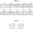
- FIG. 6 is a hardware structural diagram of the signal processing circuit 20 of the object detecting device 1 according to Embodiment 1 of the present invention.
- the filter 31 is implemented by, for example, a filter circuit 51 including a high-pass filter.
- the filter 31 removes a clutter component from the digital beat signal output by the ADC 19.
- the spectral analyzers 32a, 32b, and 32c are implemented by, for example, a semiconductor integrated circuit mounting a CPU, or a spectral analysis circuit 52 using a one-chip microprocessor and the like.
- the spectral analyzer 32a performs a process of analyzing a spectrum of the digital beat signal from which the clutter has been removed by the filter 31.
- Each of the spectral analyzers 32b and 32c performs a process of analyzing a spectrum of the digital beat signal output from the demultiplexer 24, that is, a spectrum of the digital beat signal from which the clutter has been removed by a filter 31 provided in each of the other object detecting devices 1.
- the spectral analyzers 32a, 32b, and 32c may be simply expressed as a spectral analyzer 32 when they are not needed to distinguish from each other.
- the signal processing circuit 20 since three object detecting devices 1 are provided, the signal processing circuit 20 includes three spectral analyzers 32.
- N is an integer of equal to or more than 2 object detecting devices 1 are provided, the signal processing circuit 20 includes N spectral analyzers 32.
- a search range width setter 33 is implemented by, for example, a semiconductor integrated circuit mounting a CPU, or a search range width setting circuit 53 using a one-chip microprocessor and the like.
- the search range width setter 33 calculates a distance between the object detecting device 1 and each of the other object detecting devices 1 by using the velocity and position information output from the position and velocity information outputting device 21 and the velocity and position information output from the demultiplexer 24.
- the search range width setter 33 sets a search range width for frequency by using the foregoing distance calculated in advance, a velocity indicated by the velocity and position information output from the position and velocity information outputting device 21, a velocity indicated by the velocity and position information output from the demultiplexer 24, a detectable distance range of the object 2, a detectable relative velocity range of the object 2, and individual frequency deviations of the object detecting devices 1.
- a combination target selector 34 is implemented by, for example, a semiconductor integrated circuit mounting a CPU, or a combination target selecting circuit 54 using a one-chip microprocessor and the like:
- the combination target selector 34 determines, for each spectrum analyzed by the spectral analyzer 32, a frequency search range having the search range width set by the search range width setter 33.
- the determination of the frequency search range includes a process of comparing characteristics of spectral components of each individual spectrum analyzed by the spectral analyzers 32a, 32b, and 32c, and finding, on a basis of results of the comparison, the center frequency of the search range width set by the search range width setter 33.
- the combination target selector 34 compares a characteristic of the spectral components within each determined search range, and selects, as a combination target, a frequency having a relative large spectral component from among the frequencies existing within the search range, for each of the spectra analyzed by the spectral analyzers 32a, 32b, and 32c.
- a frequency corrector 35 includes a frequency correcting amount calculator 36 and frequency correction processors 37a, 37b, and 37c.
- the frequency correcting amount calculator 36 is implemented by, for example, a semiconductor integrated circuit mounting a CPU, or a frequency correcting amount calculating circuit 55 using a one-chip microprocessor and the like.
- the frequency correcting amount calculator 36 performs a process of calculating individual frequency correcting amounts by using differences between each of the frequencies of the combination targets selected by the combination target selector 34.
- Each of the frequency correction processors 37a, 37b, and 37c is implemented by, for example, a semiconductor integrated circuit mounting a CPU, or a frequency correction processing circuit 56 using a one-chip microprocessor and the like.
- the frequency correction processor 37a performs a process of correcting the frequency of the digital beat signal, whose clutter component has been removed by the filter 31, in accordance with the frequency correcting amount calculated by the frequency correcting amount calculator 36.
- each of the frequency correction processors 37b and 37c performs a process of correcting the frequency of the digital beat signal output from the demultiplexer 24 in accordance with the frequency correcting amount calculated by the frequency correcting amount calculator 36. That is, each of the frequency correction processors 37b and 37c corrects the frequency of the digital beat signal whose clutter has been removed by a filter 31 provided in each of the other object detecting devices 1.
- the frequency correction processors 37a, 37b, and 37c may be simply expressed as a frequency correction processor 37 when they are not needed to distinguish from each other.
- the signal processing circuit 20 since three object detecting devices 1 are assumed, the signal processing circuit 20 includes three frequency correction processors 37.
- the signal processing circuit 20 includes N frequency correction processors 37.
- a coefficient determinator 38 is implemented by, for example, a semiconductor integrated circuit mounting a CPU, or a coefficient determining circuit 57 using a one-chip microprocessor and the like.
- the coefficient determinator 38 performs a process of determining, by using spectral components of the frequencies of the combination targets selected by the combination target selector 34, weighting coefficients which are used when combining the digital beat signal whose clutter has been removed by the filter 31 and the digital beat signal output from the demultiplexer 24.
- a combiner 39 is implemented by, for example, a semiconductor integrated circuit mounting a CPU, or a combining circuit 58 using a one-chip microprocessor and the like.
- the combiner 39 performs a process of combining the beat signals whose frequencies are corrected by the frequency correction processors 37a, 37b, and 37c by using the weighting coefficients determined by the coefficient determinator 38.
- An object detector 40 is implemented by, for example, a semiconductor integrated circuit mounting a CPU, or an object detecting circuit 59 using a one-chip microprocessor and the like.
- the object detector 40 detects the object 2 by performing a process of Constant False Alarm Rate (CFAR) on a beat signal combined by the combiner 39.
- CFAR Constant False Alarm Rate
- magnitude of noise is estimated by using frequencies obtained by adding a reflected wave and noise together and frequencies of noise alone, and stabilizing probability of detection errors of the noise with a CFAR threshold.
- a distance and velocity calculator 41 is implemented by, for example, a semiconductor integrated circuit mounting a CPU, or a distance and velocity calculating circuit 60 using a one-chip microprocessor and the like.
- the distance and velocity calculator 41 performs a process of calculating a distance and a relative velocity between the object detecting device 1 and the object 2 detected by the object detector 40, and outputting the calculation result to the detected-object information displaying device 25 and the object monitor 3.
- FIG. 7 is a hardware structural diagram when the signal processing circuit 20 is realized by a computer.
- a program is stored in a memory 71 of the computer, the program describing processing details of the filter 31, the spectral analyzers 32a, 32b, and 32c, the search range width setter 33, the combination target selector 34, the frequency correcting amount calculator 36, the frequency correction processor 37a, 37b, and 37c, the coefficient determinator 38, the combiner 39, the object detector 40, and the distance and velocity calculator 41, and a processor 72 of the computer executes the program stored in the memory 71.
- a processor 72 of the computer a FPGA, a DSP, a CPU, or the like is applicable.
- FIG. 8 is a flowchart illustrating the processing details of the signal processing circuit 20.
- the transmission signal generating circuit 11 generates a transmission signal by performing frequency modulation that changes frequencies over time, as illustrated in FIG. 4A .
- the transmission signal generating circuit 11 outputs the transmission signal to the transmission high-frequency circuit 12 and the beat signal extracting circuit 17.
- the transmission high-frequency circuit 12 Upon receiving the transmission signal from the transmission signal generating circuit 11, the transmission high-frequency circuit 12 performs a process of converting a frequency of the transmission signal into a carrier frequency, a filter process of removing spurious emissions and out-of-band frequencies of the transmission signal, and a process of amplifying power of the transmission signal.
- the transmission high-frequency circuit 12 outputs, as a transmission wave to the transmission antenna 13, the transmission signal on which the foregoing processes have been performed.
- the transmission wave is radiated to the space from the transmission antenna 13.
- the reception antenna 15 receives a reflected wave of the transmission wave which reflects off and returns from the object 2 to be detected after the radiation to the space by the transmission antenna 13.
- the reception antenna 15 outputs the reception signal of the reflected wave to the reception high-frequency circuit 16.
- the reception high-frequency circuit 16 Upon receiving the reception signal from the reception antenna 15, the reception high-frequency circuit 16 performs a process of converting a frequency of the reception signal into the IF frequency, a filter process of removing an image frequency during the frequency conversion and an unnecessary frequency included in the reception signal, and a process of amplifying power of the reception signal.
- the reception high-frequency circuit 16 outputs, to the beat signal extracting circuit 17, the reception signal on which the foregoing processes have been performed.
- the beat signal extracting circuit 17 Upon receiving the reception signal from the reception high-frequency circuit 16, the beat signal extracting circuit 17 extracts a beat signal from the reception signal by multiplying the reception signal and the transmission signal output from the transmission signal generating circuit 11 together, and outputs the beat signal to the reception signal processor 18.
- the beat signal indicates a difference between a frequency modulation component of the transmission signal and a frequency of the reception signal.
- the absolute value of the beat frequency of the beat signal becomes larger as a delay time becomes longer.
- the absolute value of the beat frequency in the section (a) is larger than that of the beat frequency in the section (b).
- a difference in frequency occurs among the beat frequencies of reflected waves received by the object detecting devices 1a, 1b, and 1c.
- the frequency differences among the beat frequencies of the reflected waves occur due to the Doppler shift, a delay time difference caused by space propagation, and frequency deviations inside the object detecting devices 1a, 1b, and 1c.
- FIG. 9 is an explanatory diagram for explaining a difference in beat frequency between the object detecting device 1a and the object detecting device 1b or 1c.
- the object detecting device 1m is the object detecting device 1b or the object detecting device 1c.
- the Doppler shift will be described, which is one of factors affecting the beat frequency.
- the Doppler shifts fdi and fdm are expressed by formulas (1) and (2) below.
- ⁇ is a wavelength of the transmission wave as a carrier wave and a reflected wave thereof
- v r1 is a relative velocity between the object detecting device 1a and the object 2 to be detected
- v rm is a relative velocity between the object detecting device 1m and the object 2.
- a movement vector of the object detecting device 1a is denoted as a vector v 1
- a movement vector of the object detecting device 1m is denoted as a vector v m
- a movement vector of the object 2 to be detected is denoted as a vector vt.
- each vector in the description is expressed by a "vector v" because the symbol " ⁇ " for a vector cannot be written above the corresponding character.
- a relative velocity v r1 between the object detecting device 1a and the object 2 is expressed by a formula (4) below, and a relative velocity v rm between the object detecting device 1m and the object 2 is expressed by a formula (5) below.
- v r 1 v 1 cos ⁇ 1 + v t cos ⁇ m ⁇ ⁇ m / 2
- v rm v m cos ⁇ m + v t cos ⁇ m + ⁇ m / 2
- the difference in Doppler shift ⁇ f dm between the object detecting device 1a and the object detecting device 1m can be expressed by the following parameters.
- the distance d m between the object detecting device 1a and the object detecting device 1m can be calculated from the position and velocity information output from the position and velocity information outputting device 21 connected to the object detecting device 1a, and the position and velocity information included in a multiplexed signal transmitted from the object detecting device 1m.
- the velocity v 1 of the object detecting device 1a can be calculated from the position and velocity information output from the position and velocity information outputting device 21.
- the velocity v m of the object detecting device 1m can be calculated from the position and velocity information included in the multiplexed signal transmitted from the object detecting device 1m.
- the reception antenna 15 of each of the object detecting devices 1a and 1m When a directional antenna is used as the reception antenna 15 of each of the object detecting devices 1a and 1m, the direction ⁇ 1 from the object detecting device 1a to the object 2 and the direction ⁇ m from the object detecting device 1m to the object 2 coincide with a directivity direction of a beam of the reception antenna 15. For this reason, the reception antenna 15 desirably has high directivity.
- the velocity v t of the object 2 that is a parameter depending on the object 2, the angle ⁇ m indicating the moving direction of the object 2, and the distance Ri between the object detecting device 1a and the object 2 are unknown.
- a frequency change amount is ⁇ [Hz/sec] with respect to time change per a unit time of the frequency modulation component in the transmission signal output from the transmission signal generating circuit 11
- a difference in beat frequency ⁇ f pm caused by a propagation delay difference ⁇ R between the object detecting device 1a and the object detecting device 1m is expressed by a formula (7) below.
- ⁇ f pm ⁇ R c ⁇
- c denotes the velocity of light.
- the distance d m between the object detecting device 1a and the object detecting device 1m, and the direction ⁇ 1 from the object detecting device 1a to the object 2 to be detected are known, whereas the distance Ri between the object detecting device 1a and the object 2 is unknown.
- the frequency deviation inside the object detecting devices 1a and 1m will be described. This is one of the factors affecting the beat frequency.
- the frequency deviation inside the object detecting devices 1a and 1m is a total of frequency differences of the frequency modulation components in the transmission signal generating circuit 11, the transmission high-frequency circuit 12, and the reception high-frequency circuit 16. Those frequency deviations can be determined by device design.
- ⁇ f bm ⁇ f dm + ⁇ f pm + ⁇ f s
- the difference in beat frequency ⁇ f bm between the object detecting device 1a and the object detecting device 1m is determined by the velocity v t of the object 2, the angle ⁇ m indicating the moving direction of the object 2, and the distance Ri between the object detecting device 1a and the object 2).
- the ADC 19 of the reception signal processor 18 Upon receiving the beat signal from the beat signal extractor 14, the ADC 19 of the reception signal processor 18 converts the beat signal into a digital signal and outputs the digital beat signal to the signal processing circuit 20.
- the filter 31 of the signal processing circuit 20 Upon receiving the digital beat signal from the ADC 19, the filter 31 of the signal processing circuit 20 removes a clutter component from the digital beat signal (step ST1 in FIG. 8 ).
- the digital beat signal, from which the clutter has been removed by the filter 31, is output to the spectral analyzer 32a, the frequency correction processor 37a, and the multiplexer 22.
- the position and velocity information outputting device 21 detects the position and velocity of the object detecting device 1, and outputs the position and velocity information indicating the position and velocity of the object detecting device 1 to the search range width setter 33 and the multiplexer 22.
- the multiplexer 22 multiplexes the digital beat signal output from the filter 31 and the position and velocity information output from the position and velocity information outputting device 21, and outputs the multiplexed signal to the communication device 23.
- the communication device 23 Upon receiving the multiplexed signal from the multiplexer 22, the communication device 23 transmits the multiplexed signal to each of the other object detecting devices 1.
- the other object detecting device 1 when the other object detecting device 1 combines a plurality of digital beat signals and detects the object 2 from the combined signal, the multiplexed signal is transmitted to another different object detecting device 1. However, if only a specific object detecting device 1 is configured to perform the detection process of the object 2 whereas the other object detecting devices 1 are configured not to perform the detection process of the object 2, the communication device 23 connected to the specific object detecting device 1 does not need to transmit the multiplexed signal to the other object detecting devices 1.
- the communication device 23 connected to the other object detecting device 1 transmits the multiplexed signal to the specific object detecting device 1 that performs the detection process of the object 2.
- Embodiment 1 for simplicity of explanation, the description will be made by assuming that only the object detecting device 1a performs the detection process of the object 2 and the object detecting devices 1b and 1c do not perform the detection process of the object 2.
- the communication device 23 connected to the object detecting device 1a receives the multiplexed signals transmitted from the object detecting devices 1b and 1c.
- the demultiplexer 24 Upon receiving the multiplexed signals by the communication device 23, the demultiplexer 24 de-multiplexes the multiplexed signals, and outputs a digital beat signal included in each of the multiplexed signals to the spectral analyzers 32b and 32c, and the frequency correction processors 37b and 37c.
- the demultiplexer 24 outputs the position and velocity information included in the multiplexed signals to the search range width setter 33.
- the spectral analyzer 32a Upon receiving a digital beat signal from the filter 31, the spectral analyzer 32a analyzes a spectrum of the digital beat signal (step ST2 in FIG. 8 ).
- each of the spectral analyzers 32b and 32c Upon receiving the digital beat signals from the demultiplexer 24, namely, receiving the digital beat signals, from which clutters have been removed by a filter 31 provided in each of the object detecting devices 1b and 1c, each of the spectral analyzers 32b and 32c analyzes a spectrum of the corresponding digital beat signal (step ST2 in FIG. 8 ).
- a result of the spectral analysis includes amplitude or power information as spectral components for each frequency, and also includes phase information for each frequency.
- spectral analysis of the digital beat signal in the section (a) and spectral analysis of the digital beat signal in the section (b) are performed.
- the search range width setter 33 sets ⁇ f w m ⁇ 2 that is twice a search range width ⁇ f w m for frequency according to a formula (10) below, which uses the distance d m , the velocity v 1 of the object detecting device 1a indicated by the velocity and position information output from the position and velocity information outputting device 21, the velocity v m of the object detecting device 1m indicated by the velocity and position information output from the demultiplexer 24, the detectable distance range of the object 2, the detectable relative velocity range of the object 2, and the frequency deviation ⁇ f s of the device in the object detecting device 1 and the object detecting device 1m (step ST3 in FIG. 8 ).
- ⁇ f w m max ⁇ f bm R 1 ⁇ m v t d m ⁇ 1 v 1 v m
- the search range width setter 33 assigns, to the formula (10), the distance d m between the object detecting device 1a and the object detecting device 1m, the velocities v 1 and v m , the frequency deviation ⁇ f s , and the direction ⁇ 1 from the object detecting device 1a to the object 2 to be detected, which is the directivity direction of the beam in the reception antenna 15.
- the search range width setter 33 calculates a difference in beat frequency ⁇ f bm between the object detecting device 1a and the object detecting device 1m in accordance with the formula (9) while varying the velocity v t of the object 2, the angle ⁇ m indicating the moving direction of the object 2, and the distance Ri between the object detecting device 1a and the object 2, which are unknown.
- the search range width setter 33 determines a difference in beat frequency ⁇ f bm indicating a maximum, and sets the determined difference in beat frequency ⁇ f bm to a search range width ⁇ f w m of frequency.
- the search range width setter 33 calculates the difference in Doppler shift ⁇ f dm included in the difference in beat frequency ⁇ f bm .
- a velocity in a detectable relative velocity range of the object 2 which is given from the outside, can be used for the unknown velocity v t of the object 2, and an angle in a range of 0° to 360° can be used for the unknown angle ⁇ m indicating the moving direction of the object 2.
- the search range width setter 33 calculates the difference in Doppler shift ⁇ f dm for the combination of the velocity v t of the object 2 and the angle ⁇ m indicating the moving direction of the object 2.
- the search range width setter 33 calculates in accordance with the formulas (7) and (8) the difference in beat frequency ⁇ f pm caused by the propagation delay difference ⁇ R between the object detecting device 1a and the object detecting device 1m.
- a distance in the detectable distance range of the object 2 which is given from the outside, can be used for the unknown distance Ri between the object detecting device 1a and the object 2, and the difference in beat frequency ⁇ f pm is calculated for the number of distances R 1 .
- the search range width setter 33 calculates in accordance with the formula (9) differences in beat frequency fbm between the object detecting device 1a and the object detecting device 1m by using the frequency deviation ⁇ f s while making a combination of ⁇ f dm and ⁇ f pm .
- the search range width setter 33 determines a difference in beat frequency ⁇ f bm indicating a maximum among the differences in beat frequency s f bm , and sets twice the determined difference in beat frequency ⁇ f bm as a search range width ⁇ f w m ⁇ 2.
- Embodiment 1 there are three object detecting devices 1a, 1b, and 1c. Therefore, a search range width ⁇ f w a ⁇ 2 for the object detecting device la, a search range width ⁇ f w b ⁇ 2 for the object detecting device 1b, and a search range width ⁇ f w c ⁇ 2 for the object detecting device 1c are set.
- the distance d m between the object detecting device la and the object detecting device lm, and the velocity v 1 of the object detecting device 1a and the velocity v m of the object detecting device 1m include a measurement error.
- the direction ⁇ 1 from the object detecting device la to the object 2 and the direction ⁇ m from the object detecting device 1m to the object 2 include an error with respect to an actual direction of the object 2 due to spread of the beam.
- ⁇ f w m ⁇ 2 it is desirable to set ⁇ f w m ⁇ 2 as a search range width of frequency in consideration of the errors of the distance d m , the velocities v 1 and v m , and the directions ⁇ 1 and ⁇ m .
- the combination target selector 34 determines a frequency search range having the search range width ⁇ f w m set by the search range width setter 33 for each spectrum analyzed by the spectral analyzer 32.
- the combination target selector 34 After determining the frequency search range having the search range width ⁇ f w m , the combination target selector 34 compares characteristics of spectral components in the determined search range for each spectrum analyzed by the spectral analyzer 32, and selects a frequency of a combination target from among the frequencies in the search range (step ST4 in FIG. 8 ).
- the combination target selector 34 sets each frequency of the spectrum relating to the object detecting device 1a analyzed by the spectral analyzer 32a as x, and sets the spectral component of the frequency x as f b a (x).
- the combination target selector 34 sets each frequency of the spectrum relating to the object detecting device 1b analyzed by the spectral analyzer 32b as x, and sets the spectral component of the frequency x as f b b (x).
- the combination target selector 34 sets each frequency of the spectrum relating to the object detecting device 1c analyzed by the spectral analyzer 32c as x, and sets the spectral component of the frequency x as f b c (x).
- the combination target selector 34 calculates each power pow(f b a (x)) of the spectral component f b a (x) of the corresponding frequency x, and determines maximum power max(pow(f b a (x))) among a plurality of the calculated powers pow(f b a (x)).
- the combination target selector 34 calculates each power pow(f b b (x)) of the spectral component f b b (x) of the corresponding frequency x, and determines maximum power max(pow(f b b (x))) among a plurality of the calculated powers pow(f b b (x)).
- the combination target selector 34 calculates each power pow(f b c (x)) of the spectral component f b c (x) of the corresponding frequency x, and determines maximum power max(pow(f b c (x))) among a plurality of the calculated powers pow(f b c (x)).
- the combination target selector 34 determines the largest maximum power max(pow(f b m (x))) among the maximum power max(pow(f b a (x))), the maximum power max(pow(f b b (x))), and the maximum power max(pow(f b c (x)), in accordance with a formula (11) below.
- m 1, 2, and 3.
- the combination target selector 34 determines a frequency x m max at which the largest maximum power max(pow(f b m (x))) is obtained, and the object detecting device 1 corresponding to the largest maximum power max(pow(f b m (x))).
- m x m max max max pow f b a x , max pow f b b x , max pow f b c x
- the object detecting device 1 corresponding to the largest maximum power max(pow (f b m (x))) is the object detecting device 1a.
- the combination target selector 34 sets the frequency search range for the object detecting device 1a such that a frequency x a max , at which the maximum power max(pow(f b a (x))) is obtained, becomes a center frequency of the search range width ⁇ f w a ⁇ 2 for the object detecting device 1a.
- the combination target selector 34 sets the frequency search range for the object detecting device 1a in accordance with a formula (12) below.
- the combination target selector 34 sets the frequency search range for the object detecting device 1b such that the frequency x a max , at which the maximum power max(pow(f b a (x))) is obtained, becomes a center frequency of the search range width ⁇ f w b ⁇ 2 for the object detecting device 1b.
- the combination target selector 34 sets the frequency search range for the object detecting device 1b in accordance with a formula (13) below.
- the combination target selector 34 sets the frequency search range for the object detecting device 1c such that the frequency x a max , at which the maximum power max(pow(f b a (x))) is obtained, becomes a center frequency of the search range width ⁇ f w c ⁇ 2 for the object detecting device 1c.
- the combination target selector 34 sets the frequency search range for the object detecting device 1c in accordance with a formula (14) below.
- the combination target selector 34 calculates each power pow(f b a (x)) of the spectral component f b a (x) of the corresponding frequency x in the frequency search range for the object detecting device 1a, and determines the maximum power max(pow(f b a (x))) among the calculated powers pow(f b a (x)).
- the combination target selector 34 selects a frequency x for the maximum power max(pow(f b a (x))) as a frequency x a sel of the combination target.
- the combination target selector 34 calculates each power pow(f b b (x)) of the spectral component f b b (x) of the corresponding frequency x in the frequency search range for the object detecting device 1b, and determines the maximum power max(pow(f b b (x))) among the calculated powers pow(f b b (x)).
- the combination target selector 34 selects a frequency x for the maximum power max(pow(f b b (x))) as a frequency x b sel of the combination target.
- the combination target selector 34 calculates each power pow (f b c (x)) of the spectral component f b c (x) of the corresponding frequency x in the frequency search range for the object detecting device 1c, and determines the maximum power max(pow(f b c (x))) among the calculated powers pow(f b c (x)).
- the combination target selector 34 selects a frequency x for the maximum power max(pow(f b c (x))) as a frequency x c sel of the combination target.
- abs( ⁇ ) denotes extraction of an amplitude component
- arg( ⁇ ) denotes extraction of a phase component
- the frequency correcting amount calculator 36 calculates frequency correcting amounts ⁇ x a , ⁇ x b , and ⁇ x c for the object detecting devices 1a, 1b, and 1c, respectively, with reference to the frequency x a sel of the combination target for the object detecting device 1a, as shown in formulas (15) to (17) below, for the purpose of improving the combination gain when the plurality of digital beat signals is combined by the combiner 39 (step ST7 in FIG. 8 ).
- the frequency correction processor 37a corrects the frequency of the digital beat signal, from which the clutter has been removed by the filter 31, in accordance with the frequency correcting amount ⁇ x a , as shown in a formula (18) below (step ST8 in FIG. 8 ).
- s a c t s a t ⁇ exp ⁇ ⁇ x a ⁇ 2 ⁇ ⁇ ⁇ DataInterval ⁇ t
- s a (t) represents a time series signal of the digital beat signal output from the filter 31, and s a c (t) represents a time series signal of the digital beat signal after the frequency correction.
- DataInterval is a sample time interval of the time series signal, and t is a sample number. The sample number is an integer.
- the frequency correction processor 37b corrects the frequency of the digital beat signal output from the demultiplexer 24, that is, the frequency of the digital beat signal, from which the clutter has been removed by the filter 31 of the object detecting device 1b, in accordance with the frequency correcting amount ⁇ x b , as shown in a formula (19) below (step ST8 in FIG. 8 ).
- s b c t s b t ⁇ exp ⁇ ⁇ x b ⁇ 2 ⁇ ⁇ ⁇ DataInterval ⁇ t
- s b (t) represents a time series signal of the digital beat signal output from the filter 31 of the object detecting device 1b
- s b c (t) represents a time series signal of the digital beat signal after the frequency correction.
- the frequency correction processor 37c corrects the frequency of the digital beat signal output from the demultiplexer 24, that is, the frequency of the digital beat signal, from which the clutter has been removed by the filter 31 of the object detecting device 1c, in accordance with the frequency correcting amount ⁇ x c , as shown in a formula (20) below (step ST8 in FIG. 8 ).
- s c c t s c t ⁇ exp ⁇ ⁇ x c ⁇ 2 ⁇ ⁇ ⁇ DataInterval ⁇ t
- s c (t) represents a time series signal of the digital beat signal output from the filter 31 of the object detecting device 1c
- s c c (t) represents a time series signal of the digital beat signal after the frequency correction.
- the coefficient determinator 38 determines weighting coefficients w a , w b , and w c used for combining the digital beat signals whose frequencies have been corrected by the frequency correction processors 37a, 37b, and 37c, in accordance with formulas (21) to (23) below (step ST9 in FIG. 8 ).
- the combiner 39 combines the time series signals s a c (t), s b c (t), and s c c (t) of the digital beat signals, whose frequencies have been corrected by the frequency correction processors 37a, 37b and 37c, by using the weighting coefficients w a , w b , and w c in accordance with a formula (24) below (step ST10 in FIG. 8 ).
- y t w a s a c t + w b s b c t + w c s c c t
- the combiner 39 outputs a combined signal y(t) to the object detector 40.
- the weighting coefficients w a , w b , and w c determined by the coefficient determinator 38 are the weights of maximum ratio combining, the signal power to noise power ratio is maximized by a combining process according to the formula (24).
- the object detector 40 Upon receiving the combined signal y(t) from the combiner 39, the object detector 40 detects the object 2 by performing the CFAR processing on the signal y(t) (step ST11 in FIG. 8 ).
- the object detector 40 analyzes the spectrum of the combined signal y(t), and determines that the object 2 to be detected exists when there is a spectral component equal to or more than the CFAR threshold, which has been given from the outside, among the spectral components of frequencies of the spectrum.
- the object detector 40 When it is determined that the object 2 to be detected exists, the object detector 40 outputs, as the beat frequency, a frequency corresponding to the spectral component equal to or more than the CFAR threshold to the distance and velocity calculator 41.
- the distance and velocity calculator 41 Upon receiving the beat frequency from the object detector 40, the distance and velocity calculator 41 calculates, by using the beat frequency, the distance Ri from the object detecting device 1a to the object 2, and also calculates the relative velocity v r between the object detecting device 1a and the object 2 (step ST12 in FIG. 8 ).
- the distance Ri from the object detecting device 1a to the object 2 and the relative velocity v r between the object detecting device 1a and the object 2 can be calculated by solving equations shown in a formula (25) below.
- c is the velocity of light
- ⁇ is a wavelength of the carrier wave
- ⁇ A is a change amount of frequency with respect to the time change per unit time of the frequency modulation component in the section (a)
- ⁇ B is a frequency change amount with respect to the time change per unit time of the frequency modulation component in the section (b).
- the distance and velocity calculator 41 After calculating the distance Ri from the object detecting device 1a to the object 2, and the relative velocity v r between the object detecting device 1a and the object 2, the distance and velocity calculator 41 outputs the distance Ri and the relative velocity v r to the detected-object information displaying device 25 and the object monitor 3.
- the distance Ri calculated by the distance and velocity calculator 41 may exceed the detectable distance range assumed in the object detecting device 1a.
- the relative velocity v r calculated by the distance and velocity calculator 41 may exceed the detectable relative velocity range assumed in the object detecting device 1a.
- the distance Ri calculated by the distance and velocity calculator 41 exceeds the detectable distance range assumed in the object detecting device 1a, or when the relative velocity v r calculated by the distance and velocity calculator 41 exceeds the detectable relative velocity range assumed in the object detecting device 1a, it is desirable that the distance Ri and the relative velocity v r are not output to the detected-object information displaying device 25 and the object monitor 3.
- the detected-object information displaying device 25 Upon receiving, from the distance and velocity calculator 41, the distance Ri from the object detecting device 1a to the object 2, and the relative velocity v r between the object detecting device 1a and the object 2, the detected-object information displaying device 25 displays the distance Ri and the relative velocity v r on the display.
- the object monitor 3 Upon receiving, from the distance and velocity calculator 41, the distance Ri from the object detecting device 1a to the object 2, and the relative velocity v r between the object detecting device 1a and the object 2, the object monitor 3 performs a process of monitoring the object 2 by using the distance Ri and the relative velocity v r .
- the monitoring processing of the object 2 by the object monitor 3 includes a process of recording a relative velocity v r and a distance Ri to the object 2 detected by the object detecting device 1 and monitoring change in the position and velocity of the object 2, a process of predicting the future position and velocity of the object 2, and the like.
- the spectral analyzers 32a, 32b, and 32c for analyzing a spectrum of the beat signal extracted by the beat signal extractor 14 and the spectra of the beat signals extracted by the object detecting devices 1b and 1c; the search range width setter 33 for setting a search range width for frequency; the combination target selector 34 for determining a frequency search range having the search range width set by the search range width setter 33, comparing spectral components of frequencies in the search range, and selecting, for each spectrum analyzed by the spectral analyzers 32a, 32b, and 32c, a frequency of a combination target from among the frequencies existing within the search range; and the frequency corrector 35 for calculating frequency correcting amounts from differences between each of the frequencies of the combination targets selected by the combination target selector 34, and correcting a frequency of the beat signal extracted by the beat signal extractor 14 and frequencies of the beat signals extracted by the object detecting devices 1b and 1c in accordance with each of the frequency correct
- Embodiment 1 by selecting frequencies of combination targets from among frequencies included in the reflected waves received by the object detecting devices 1a, 1b, and 1c by the search range width setter 33, the probability of erroneously combining frequencies, which are not relating to the object 2, is reduced.
- the frequencies of the beat signals extracted by the object detecting devices 1a, 1b, and 1c are corrected by the frequency corrector 35. Therefore, even when the frequencies of the beat signals extracted by the object detecting devices 1a, 1b, and 1c are different from each other, it is possible to suppress a decrease in gain caused by combination.
- the beat signals whose frequencies are corrected by the frequency corrector 35 are combined by the combiner 39, whereby a combined signal is obtained with an improved signal power to noise power ratio. For this reason, object detection accuracy in the object detector 40 and the calculation accuracy of the distance and velocity in the distance and velocity calculator 41 are improved.
- Embodiment 1 when the plurality of object detecting devices 1 is installed apart from each other, the beat signals extracted by the plurality of object detecting devices 1 can be combined without calculating the distances among the object detecting devices 1 in the wavelength order.
- the distances among the plurality of object detecting devices 1 are fixed, namely for example, when the plurality of object detecting devices 1 is fixed on the ground, or when the plurality of object detecting devices 1 is installed in one moving platform, the distances do not change over time. Therefore, even if lowering the accuracy of the distances among the object detecting devices 1, it is possible to obtain a combined signal of the plurality of beat signals capable of enhancing the detection probability of the object 2.
- the object detecting devices 1 are installed on different moving platforms from each other, and the distances among the object detecting devices 1 are fixed, it is possible to obtain a combined signal of the plurality of beat signals capable of enhancing the detection probability of the object 2 even if lowering the accuracy of the distance between the plurality of object detecting devices 1.
- the object detecting device 1 detects the object 2 by the distance measurement system called as the FMCW system
- the present invention is not limited thereto.
- the object 2 may be detected by a distance measurement system called as a frequency modulation interrupted continuous wave (FMICW) system.
- FMICW frequency modulation interrupted continuous wave
- FIG. 10 is an explanatory diagram illustrating the transmission wave and reflected wave and the beat signal.
- FIG. 10A illustrates a transmission signal including a plurality of pulses
- FIG. 10B illustrates a reception signal including a plurality of pulses.
- FIG. 10C illustrates the transmission wave and reflected wave whose frequencies change over time
- FIG. 10D illustrates the beat signal whose beat frequency changes over time.
- a transmission signal generated by the transmission signal generating circuit 11 forms a pulse train as illustrated in FIG. 10A .
- a transmission wave illustrated in FIG. 10C on which the frequency modulation similar to the FMCW system has been performed, is radiated from the transmission antenna 13.
- a reflected wave received by the reception antenna 15 is received as a pulse train with a propagation delay as illustrated in FIGS. 10B and 10C .
- the reflected wave has time delays as illustrated in FIG. 10C , and the frequency of the reflected wave is frequency-shifted by the Doppler shift.
- the beat signal extracting circuit 17 takes a difference between the reception signal of the reflected wave and the frequency modulation component of the transmission signal generated by the transmission signal generating circuit 11.
- the frequency modulation component is the same as in the case of the FMCW system.
- the output of the beat signal extracting circuit 17 forms a pulse train having a beat frequency similarly to the case of the FMCW system.
- FIG. 11 is an explanatory diagram illustrating an output signal of the beat signal extracting circuit 17.
- FIG. 11A illustrates the output signal of the beat signal extracting circuit 17, and FIG. 11B illustrates the spectrum in a case where the Doppler shift does not occur in the reflected wave.
- FIG. 11C illustrates the spectrum in a case where the Doppler shift occurs in the reflected wave
- FIG. 11D is a diagram obtained by enlarging a vicinity of a frequency of 0 Hz in FIG. 11C .
- n is an arbitrary integer other than zero.
- the spectrum of the reception pulse train as the reception signal becomes a spectrum with an envelope, which is repeated every 1/T, as illustrated in FIGS. 11C and 11D .
- the reception pulse train which has the spectrum illustrated in FIGS. 11C and 11D , is sampled by the ADC 19 and input to the filter 31.
- the signal processing circuit 20 is configured as illustrated in FIG. 12 .
- the filter 31 of the signal processing circuit 20 in FIG. 12 extracts only the filter extraction portions illustrated in FIG. 11D in order to remove the clutter near 0 Hz and also remove the repetitive portions of the spectrum repeated every 1/T.
- a sample data decimator 42 is provided for performing a process of narrowing the representation band of the time series signal of the output signal of the filter 31.
- the subsequent processing is similar to the case of the FMCW system.
- the combination target selector 34 selects, as a frequency of a combination target, a frequency having a relative large spectral component among frequencies existing within the search range. With this configuration, it may be possible to select a frequency of the object 2 to be detected. On the other hand, when the frequency of the object 2 is not actually included in the frequencies in the search range, noise in the reflected wave may be selected as the frequency of the combination target.
- Example 1 in order not to select the noise in the reflected wave as the frequency of the combination target, the combination target selector 34 selects a frequency, whose spectral component is larger than a threshold, among the frequencies existing within the search range.
- Example 1 is not an embodiment of the present invention but is helpful for understanding certain aspects thereof.
- the combination target selector 34 sets each frequency of the spectrum relating to the object detecting device 1a analyzed by the spectral analyzer 32a as x, and sets the spectral component of the frequency x as f b a (x), and calculates each power pow(f b a (x)) of the spectral component f b a (x) of the corresponding frequency x.
- the combination target selector 34 sets each frequency of the spectrum relating to the object detecting device 1b analyzed by the spectral analyzer 32b as x, sets the spectral component of the frequency x as f b b (x), and calculates each power pow(f b b (x)) of the spectral component f b b (x) of the corresponding frequency x.
- the combination target selector 34 sets each frequency of the spectrum relating to the object detecting device 1c analyzed by the spectral analyzer 32c as x, sets the spectral component of the frequency x as f b c (x), and calculates each power pow(f b c (x)) of the spectral component f b c (x) of the corresponding frequency x.
- the combination target selector 34 compares each power pow(f b a (x)) of the spectral component f b a (x) of the corresponding frequency x with a preset threshold. When there is power pow(f b a (x)) larger than the threshold among the powers pow(f b a (x)) of respective frequencies x, the combination target selector 34 selects, as a frequency x a sel of a combination target, a frequency of the power pow(f b a (x)) larger than the threshold.
- the combination target selector 34 compares each power pow(f b b (x)) of the spectral component f b b (x) of the corresponding frequency x with a preset threshold. When there is power pow(f b b (x)) larger than the threshold among the powers pow(f b b (x)) of respective frequencies x, the combination target selector 34 selects, as a frequency x b sel of a combination target, a frequency of the power pow(f b b (x)) larger than the threshold.
- the combination target selector 34 compares each power pow(f b c (x)) of the spectral component f b c (x) of the corresponding frequency x with a preset threshold. When there is power pow(f b c (x)) larger than the threshold among the powers pow(f b c (x)) of respective frequencies x, the combination target selector 34 selects, as a frequency x c sel of a combination target, a frequency of the power pow(f b c (x)) larger than the threshold.
- the combination target selector 34 compares the power of a spectral component of each frequency x with the threshold.
- the amplitude of the spectral component of each frequency x may be compared with the threshold.
- the frequency correcting amount calculator 36 sets the frequency correcting amounts ⁇ x a , ⁇ x b , and ⁇ x c for the object detecting devices 1a, 1b, and 1c, respectively, to zero.
- the frequency correcting amount calculator 36 calculates the frequency correcting amounts ⁇ x a , ⁇ x b , and ⁇ x c in the following manner.
- the frequency correcting amount calculator 36 calculates the frequency correcting amounts ⁇ x a1 , ⁇ x b1 , ⁇ xb 2 , and ⁇ x c1 for the object detecting devices 1a, 1b, and 1c, with reference to the frequency x a sel1 .
- the frequency correcting amount calculator 36 calculates the frequency correcting amounts ⁇ x a2 , ⁇ x b3 , ⁇ x b4 , and ⁇ x c2 for the object detecting devices 1a, 1b, and 1c, with reference to the frequency x a sel2 .
- the frequency correction processor 37a corrects the frequency of the digital beat signal, from which the clutter has been removed by the filter 31, in accordance with the frequency correcting amount ⁇ xa1 and ⁇ x a2 , as shown in formulas (34) and (35) below.
- s a1 c (t) represents a time series signal of the digital beat signal corrected by the frequency correcting amount ⁇ x a1
- s a2 c(t) represents a time series signal of the digital beat signal corrected by the frequency correcting amount ⁇ x a2 .
- the frequency correction processor 37b corrects the frequency of the digital beat signal output from the demultiplexer 24, that is, the frequency of digital beat signal, from which the clutter has been removed by the filter 31 of the object detecting device 1b, in accordance with the frequency correcting amounts ⁇ x b1 , ⁇ xb 2 , ⁇ xb 3 , and ⁇ xb 4 , as shown in formulas (36) to (39) below.
- s b1 c (t) represents a time series signal of the digital beat signal corrected by the frequency correcting amount ⁇ x b1
- sb 2 c (t) represents a time series signal of the digital beat signal corrected by the frequency correcting amount ⁇ xb 2
- sb 3 c (t) represents a time series signal of the digital beat signal corrected by the frequency correcting amount ⁇ xb 3
- sb 4 c (t) represents a time series signal of the digital beat signal corrected by the frequency correcting amount ⁇ x b4 .
- the frequency correction processor 37c corrects the frequency of the digital beat signal output from the demultiplexer 24, that is, the frequency of the digital beat signal, from which the clutter has been removed by the filter 31 of the object detecting device 1c, in accordance with the frequency correcting amounts ⁇ x c1 and ⁇ x c2 , as shown in formulas (40) to (41) below.
- s c1 c (t) represents a time series signal of the digital beat signal corrected by the frequency correcting amount ⁇ x c1
- s c2 c(t) represents a time series signal of the digital beat signal corrected by the frequency correcting amount ⁇ x c2 .
- the coefficient determinator 38 determines weighting coefficients w 1 a to w 4 a , w 1 b to w 4 b , and w 1 c to w 4 c used for combining the digital beat signals, whose frequencies have been corrected by the frequency correction processors 37a, 37b and 37c, for the combination of the frequencies x a sel1 and x a sel
- the combiner 39 combines, by using the weighting coefficients for each combination as shown in formulas (54) to (57) below, the time series signals being the beat signals whose frequency have been corrected by the frequency correction processors 37a, 37b, and 37c.
- Example 1 similarly to Embodiment 1, it is capable of bringing an effect of enhancing the detection probability of the object 2 to be detected without acquiring the position information of the object 2 in advance. In addition, it is possible to reduce the probability of erroneously selecting the noise of the reflected wave as a frequency of a combination target.
- the combination target selector 34 selects a frequency having a relative large spectral component as a frequency of a combination target from among frequencies in the search range. In the foregoing Example 1, the combination target selector 34 selects a frequency having a spectral component larger than a threshold as a frequency of a combination target from among frequencies in the search range.
- Example 2 that will be described hereinafter, a frequency, which has a relative large spectral component and whose spectral component is larger than a threshold, is selected as a frequency of a combination target from among frequencies existing within the search range.
- Example 2 is not an embodiment of the present invention but is helpful for understanding certain aspects thereof.
- FIG. 13 is a structural diagram illustrating a signal processing circuit 20 of an object detecting device 1 according to Example 2 and in the figure, since the same reference numerals as those in FIG. 5 denote the same or corresponding portions, the description thereof will be omitted.
- a combination target selector 43 is implemented by the combination target selecting circuit 54 illustrated in FIG. 6 , and performs a process of selecting a frequency of a combination target.
- a combination target limiter 44a compares characteristics of spectral components in spectra analyzed by the spectral analyzer 32a with the threshold, and performs processing of selecting a frequency whose spectral component is larger than the threshold.
- a combination target limiter 44b compares characteristics of spectral components in spectra analyzed by the spectral analyzer 32b with the threshold, and performs processing for selecting a frequency whose spectral component is larger than the threshold.
- a combination target limiter 44c compares characteristics of spectral components in spectra analyzed by the spectral analyzer 32c with the threshold, and performs processing for selecting a frequency whose spectral component is larger than the threshold.
- a combination target selecting processor 45 selects a frequency having a relative large characteristic of a spectral component from among the frequencies selected by the combination target limiter 44a as a frequency of a combination target, also selects a frequency having a relative large characteristic of a spectral component from among the frequencies selected by the combination target limiter 44b as a frequency of a combination target, and also selects a frequency having a relative large characteristic of a spectral component from among the frequencies selected by the combination target limiter 44c as a frequency of a combination target.
- Example 2 an example will be described, in which the combination target selector 43 is applied to the signal processing circuit 20 in FIG. 5 .
- the combination target selector 43 may be applied to the signal processing circuit 20 in FIG. 12 .
- the combination target limiter 44a sets each frequency of the spectrum relating to the object detecting device 1a analyzed by the spectral analyzer 32a as x, sets the spectral component of the frequency x as f b a (x), and calculates each power pow(f b a (x)) of the spectral component f b a (x) of the corresponding frequency x.
- the combination target limiter 44b sets each frequency of the spectrum relating to the object detecting device 1b analyzed by the spectral analyzer 32b as x, sets the spectral component of the frequency x as f b b (x), and calculates each power pow(f b b (x)) of the spectral component f b b (x) of the corresponding frequency x.
- the combination target limiter 44c sets each frequency of the spectrum relating to the object detecting device 1c analyzed by the spectral analyzer 32c as x, sets the spectral component of the frequency x as f b c (x), and calculates each power pow(f b c (x)) of the spectral component f b c (x) of the corresponding frequency x.
- the combination target limiter 44a compares each power pow(f b a (x)) of the spectral component f b a (x) of the corresponding frequency x with a preset threshold. When there is power pow(f b a (x)) larger than the threshold among the powers pow(f b a (x)) of respective frequencies x, the combination target limiter 44a selects a frequency x of the power pow(f b a (x)).
- the combination target limiter 44b compares each power pow(f b b (x)) of the spectral component f b b (x) of the corresponding frequency x with a preset threshold. When there is power pow(f b b (x)) larger than the threshold among the powers pow(f b b (x)) of respective frequencies x, the combination target limiter 44b selects a frequency x of the power pow(f b b (x)).
- the combination target limiter 44c compares each power pow(f b c (x)) of the spectral component f b c (x) of the corresponding frequency x with a preset threshold. When there is power pow(f b c (x)) larger than the threshold among the powers pow(f b c (x)) of respective frequencies x, the combination target limiter 44c selects a frequency x of the power pow(f b c (x)).
- the combination target limiters 44a, 44b, and 44c compare the power of the spectral component of each frequency x with the threshold.
- the amplitude of the spectral component of each frequency x may be compared with the threshold.
- the combination target selecting processor 45 compares powers pow(f b a (x)) of the respective spectral component f b a (x) of one or more frequencies x with each other, and selects a frequency x of the largest power pow(f b a (x)) as a frequency x a sel of a combination target.
- the combination target selecting processor 45 compares powers pow(f b b (x)) of the respective spectral component f b b (x) of one or more frequencies x with each other, and selects a frequency x of the largest power pow(f b b (x)) as a frequency x b sel of a combination target.
- the combination target selecting processor 45 compares powers pow(f b c (x)) of the respective spectral component f b c (x) of one or more frequencies x with each other, and selects a frequency x of the largest power pow(f b c (x)) a frequency x c sel of a combination target.
- Example 2 similarly to the foregoing Embodiment 1, there are effects that it is possible to enhance the detection probability of the object 2 to be detected without acquiring the position information of the object 2 in advance, and it is possible to reduce the possibility of erroneously selecting the noise included in the reflected wave as a frequency of a combination target.
- the object detecting device is suitable for high precision detection of an object existing in a space.
- 1a, 1b, 1c Object detecting device; 2: Object to be detected; 3: Object monitor; 11: Transmission signal generating circuit; 12: Transmission high-frequency circuit; 13: Transmission antenna; 14: Beat signal extractor; 15: Reception antenna; 16: Reception high-frequency circuit; 17: Beat signal extracting circuit; 18: Reception signal processor; 19: ADC; 20: Signal processing circuit; 21: Position and velocity information outputting device; 22: Multiplexer; 23: Communication device; 24: Demultiplexer; 25: Detected-object information displaying device; 31: Filter, 32a, 32b, 32c: Spectral analyzer; 33: Search range width setter; 34: Combination target selector; 35: Frequency corrector; 36: Frequency correcting amount calculator; 37a, 37b, 37c: Frequency correction processor; 38: Coefficient determinator; 39: Combiner; 40: Object detector; 41: Distance and velocity calculator; 42: Sample data decimator; 43: Combination target selector; 44a, 44b,
Landscapes
- Engineering & Computer Science (AREA)
- Radar, Positioning & Navigation (AREA)
- Remote Sensing (AREA)
- Physics & Mathematics (AREA)
- Computer Networks & Wireless Communication (AREA)
- General Physics & Mathematics (AREA)
- Electromagnetism (AREA)
- Signal Processing (AREA)
- Radar Systems Or Details Thereof (AREA)
Claims (2)
- Dispositif de détection d'objet (1a) parmi une pluralité de dispositifs de détection d'objet (1a, 1b, 1c) qui détectent un objet, chacun des dispositifs de détection d'objet comprenant :un circuit haute fréquence de transmission (12) ;un circuit de génération de signal de transmission (11) configuré de manière à fournir en sortie un signal de transmission au circuit haute fréquence de transmission (12) ;un extracteur de signal de battement (14) configuré de manière à recevoir un signal qui se reflète sur un objet à détecter, et à extraire un signal de battement du signal reçu, dans lequel l'extracteur de signal de battement (14) comprend un circuit haute fréquence de réception (16) configuré de manière à mettre en œuvre un processus de conversion de fréquence consistant à convertir la fréquence du signal reçu en vue de générer un signal de réception, et un circuit d'extraction de signal de battement (17) configuré de manière à extraire le signal de battement du signal de réception, en multipliant ensemble le signal de réception et le signal de transmission fourni en sortie à partir du circuit de génération de signal de transmission (11) ;un dispositif de fourniture en sortie d'informations de position et de vitesse (21) configuré de manière à détecter une position et une vitesse du dispositif de détection d'objet (1a) et configuré de manière à fournir en sortie des premières informations de position et de vitesse indiquant la position et la vitesse du dispositif de détection d'objet (1a) ;un multiplexeur (22) configuré de manière à multiplexer le signal de battement extrait et les premières informations de position et de vitesse fournies en sortie à partir du dispositif de fourniture en sortie d'informations de position et de vitesse (21), en vue de générer un premier signal multiplexé ;un dispositif de communication (23) configuré de manière à transmettre le premier signal multiplexé à un autre dispositif de détection d'objet (1b ; 1c) et à recevoir un second signal multiplexé en provenance dudit autre dispositif de détection d'objet (1b ; 1c) ;un démultiplexeur (24) configuré de manière à démultiplexer le second signal multiplexé en vue de générer un signal de battement extrait par ledit autre dispositif de détection d'objet (1b ; 1c) et des secondes informations de position et de vitesse indiquant la position et la vitesse dudit autre dispositif de détection d'objet (1b ; 1c) ;un analyseur spectral (32) configuré de manière à analyser un spectre du signal de battement extrait par l'extracteur de signal de battement (14) et un spectre du signal de battement extrait par ledit autre dispositif de détection d'objet (1b ; 1c) ;un module de réglage de largeur de plage de recherche (33) configuré de manière à calculer une distance entre le dispositif de détection d'objet (1a) et ledit autre dispositif de détection d'objet (1b ; 1c), en utilisant les premières informations de vitesse et de position fournies en sortie et les secondes informations de vitesse et de position fournies en sortie, et configuré de manière à régler une largeur de plage de recherche en ce qui concerne la fréquence, en utilisant la distance calculée entre le dispositif de détection d'objet (1a) et ledit autre dispositif de détection d'objet (1b ; 1c), une vitesse indiquée par les premières informations de vitesse et de position, une vitesse indiquée par les secondes informations de vitesse et de position, une plage de distance détectable de l'objet (2), une plage de vitesse relative détectable de l'objet (2), et des écarts de fréquence individuels du dispositif de détection d'objet (1a) et dudit autre dispositif de détection d'objet (1b ; 1c), dans lequel l'écart de fréquence individuel du dispositif de détection d'objet (1a) correspond à un total de différences de fréquence de composantes de modulation de fréquence dans le circuit de génération de signal de transmission (11), le circuit haute fréquence de transmission (12) et le circuit haute fréquence de réception (16) du dispositif de détection d'objet (1a), et dans lequel l'écart de fréquence individuel dudit autre dispositif de détection d'objet (1b ; 1c) correspond à un total de différences de fréquence de composantes de modulation de fréquence dans le circuit de génération de signal de transmission (11), le circuit haute fréquence de transmission (12) et le circuit haute fréquence de réception (16) dudit autre dispositif de détection d'objet (1b ; 1c) ;un sélecteur de cibles de combinaison (34) configuré de manière à :- déterminer, pour chaque spectre analysé par l'analyseur spectral (32), une plage de recherche de fréquence dont la largeur de plage de recherche est réglée par le module de réglage de largeur de plage de recherche (33) ; et- sélectionner, pour chacun des spectres analysés, une fréquence d'une cible de combinaison, en comparant une caractéristique des composantes spectrales dans chaque plage de recherche déterminée, dans lequel le sélecteur de cibles de combinaison (34) sélectionne, en tant que la fréquence de la cible de combinaison, une fréquence dont une caractéristique de la composante spectrale est supérieure à un seuil parmi les fréquences dans la plage de recherche ;un correcteur de fréquence (35) configuré de manière à :- calculer des quantités de correction de fréquences individuelles à partir de différences entre chacune des fréquences des cibles de combinaison sélectionnées par le sélecteur de cibles de combinaison (34) ; et- corriger une fréquence du signal de battement extrait par l'extracteur de signal de battement (14) et une fréquence du signal de battement extrait par ledit autre dispositif de détection d'objet (1b ; 1c) selon chacune des quantités de correction de fréquence calculées ;un combineur (39) configuré de manière à combiner les signaux de battement, dont chacune des fréquences a été corrigée par le correcteur de fréquence (35) ; etun détecteur d'objet (39) configuré de manière à détecter l'objet à partir d'un signal de battement combiné obtenu par le combineur (39).
- Dispositif de détection d'objet selon la revendication 1, comprenant en outre un module de détermination de coefficients (38) configuré de manière à déterminer des coefficients de pondération à partir des caractéristiques des composantes spectrales des cibles de combinaison sélectionnées par le sélecteur de cibles de combinaison (34), les coefficients de pondération étant utilisés en vue de combiner le signal de battement extrait par l'extracteur de signal de battement (14) et le signal de battement extrait par ledit autre dispositif de détection d'objet (1b ; 1c) ;
dans lequel le combineur (39) combine les signaux de battement, dont les fréquences ont été corrigées par le correcteur de fréquence (35), en utilisant les coefficients de pondération déterminés par le module de détermination de coefficients (38).
Applications Claiming Priority (1)
| Application Number | Priority Date | Filing Date | Title |
|---|---|---|---|
| PCT/JP2016/054463 WO2017141352A1 (fr) | 2016-02-16 | 2016-02-16 | Dispositif de détection d'objets et dispositif formant capteur |
Publications (3)
| Publication Number | Publication Date |
|---|---|
| EP3399334A1 EP3399334A1 (fr) | 2018-11-07 |
| EP3399334A4 EP3399334A4 (fr) | 2018-12-19 |
| EP3399334B1 true EP3399334B1 (fr) | 2020-12-16 |
Family
ID=59625696
Family Applications (1)
| Application Number | Title | Priority Date | Filing Date |
|---|---|---|---|
| EP16890494.4A Active EP3399334B1 (fr) | 2016-02-16 | 2016-02-16 | Dispositif de détection d'objets et dispositif formant capteur |
Country Status (6)
| Country | Link |
|---|---|
| US (1) | US11041953B2 (fr) |
| EP (1) | EP3399334B1 (fr) |
| JP (1) | JP6279193B2 (fr) |
| AU (1) | AU2016392920B2 (fr) |
| CA (1) | CA3014156C (fr) |
| WO (1) | WO2017141352A1 (fr) |
Families Citing this family (5)
| Publication number | Priority date | Publication date | Assignee | Title |
|---|---|---|---|---|
| JP6992704B2 (ja) * | 2018-08-22 | 2022-01-13 | 株式会社デンソー | 物体検知装置 |
| FR3090892B1 (fr) * | 2018-12-20 | 2021-06-25 | Thales Sa | Procédé de mesure de distance par transformée de Fourier adaptée et système radar pour la mise en œuvre du procédé |
| WO2021224952A1 (fr) * | 2020-05-07 | 2021-11-11 | 合同会社パッチドコニックス | Système de communication et procédé de traitement de signal |
| US20210405189A1 (en) * | 2020-06-30 | 2021-12-30 | Izak Jan van Cruyningen | Range Determination from Differential Atmospheric Acoustic Absorption |
| JP2022090856A (ja) | 2020-12-08 | 2022-06-20 | ソニーセミコンダクタソリューションズ株式会社 | 測距装置、および測距方法、並びにプログラム |
Family Cites Families (13)
| Publication number | Priority date | Publication date | Assignee | Title |
|---|---|---|---|---|
| JP3001405B2 (ja) * | 1995-10-24 | 2000-01-24 | 日本電気株式会社 | インターフェロメトリsar方式 |
| JP2935419B2 (ja) * | 1996-11-15 | 1999-08-16 | 本田技研工業株式会社 | Fmレーダ装置 |
| US6317073B1 (en) | 1998-09-07 | 2001-11-13 | Denso Corporation | FM-CW radar system for measuring distance to and relative speed of a target |
| JP3332000B2 (ja) * | 1999-02-12 | 2002-10-07 | 日本電気株式会社 | Sar装置 |
| JP3866048B2 (ja) * | 2001-03-14 | 2007-01-10 | 三菱電機株式会社 | 画像レーダ装置 |
| JP2004233277A (ja) * | 2003-01-31 | 2004-08-19 | Denso Corp | 車両用レーダ装置 |
| WO2005124388A1 (fr) * | 2004-06-21 | 2005-12-29 | Fujitsu Ten Limited | Appareil radar |
| JP5594946B2 (ja) * | 2008-08-21 | 2014-09-24 | 三菱電機株式会社 | レーダ画像処理装置 |
| JP2011247597A (ja) * | 2010-05-21 | 2011-12-08 | Mitsubishi Electric Corp | レーダ信号処理装置 |
| JP5631763B2 (ja) | 2010-08-23 | 2014-11-26 | 株式会社東芝 | Mimoレーダシステム、送信装置、受信装置及びmimoレーダ信号処理方法 |
| CN103323842A (zh) * | 2012-09-03 | 2013-09-25 | 中国科学院电子学研究所 | 一种调频连续波合成孔径雷达中的成像方法及装置 |
| JP6292601B2 (ja) | 2012-11-30 | 2018-03-14 | 三菱重工業株式会社 | レーダシステム、サブモジュール、レーダ処理方法 |
| DE102013200951A1 (de) * | 2013-01-22 | 2014-07-24 | Robert Bosch Gmbh | FMCW-Radar mit Abstandsbereichseinteilung |
-
2016
- 2016-02-16 EP EP16890494.4A patent/EP3399334B1/fr active Active
- 2016-02-16 US US16/065,653 patent/US11041953B2/en active Active
- 2016-02-16 WO PCT/JP2016/054463 patent/WO2017141352A1/fr not_active Ceased
- 2016-02-16 JP JP2017561429A patent/JP6279193B2/ja not_active Expired - Fee Related
- 2016-02-16 AU AU2016392920A patent/AU2016392920B2/en active Active
- 2016-02-16 CA CA3014156A patent/CA3014156C/fr active Active
Non-Patent Citations (1)
| Title |
|---|
| None * |
Also Published As
| Publication number | Publication date |
|---|---|
| WO2017141352A1 (fr) | 2017-08-24 |
| US20190004175A1 (en) | 2019-01-03 |
| EP3399334A4 (fr) | 2018-12-19 |
| CA3014156A1 (fr) | 2017-08-24 |
| CA3014156C (fr) | 2019-01-08 |
| JP6279193B2 (ja) | 2018-02-14 |
| JPWO2017141352A1 (ja) | 2018-02-22 |
| US11041953B2 (en) | 2021-06-22 |
| AU2016392920B2 (en) | 2018-11-15 |
| EP3399334A1 (fr) | 2018-11-07 |
| AU2016392920A1 (en) | 2018-07-05 |
Similar Documents
| Publication | Publication Date | Title |
|---|---|---|
| US10557933B2 (en) | Radar device and position-determination method | |
| US9971028B2 (en) | Method and apparatus for detecting target using radar | |
| US9921305B2 (en) | Radar apparatus and object sensing method | |
| US11885905B2 (en) | Radar apparatus and method for determining range side lobe | |
| CN108885254B (zh) | 物体检测装置 | |
| JP2016151425A (ja) | レーダ装置 | |
| JP2019074527A (ja) | 干渉抑制を用いるレーダー検出 | |
| JP5251591B2 (ja) | パルス圧縮装置 | |
| US7961147B1 (en) | Long baseline phase interferometer ambiguity resolution using frequency differences | |
| US20170307727A1 (en) | Fmcw radar device | |
| WO2013080570A1 (fr) | Dispositif radar | |
| US11041953B2 (en) | Object detecting device and sensor device | |
| US20170242116A1 (en) | Radar apparatus and radar method | |
| JP2009025159A (ja) | レーダ装置 | |
| JP6324327B2 (ja) | パッシブレーダ装置 | |
| JP2016151424A (ja) | レーダ装置 | |
| GB2568615B (en) | Object detection device, object detection method, and sensor device | |
| JP5057840B2 (ja) | スペクトル解析装置 | |
| JP2010175457A (ja) | レーダ装置 | |
| KR20200053222A (ko) | 거리, 각도 속도를 정밀 측정하기 위한 레이더 장치 및 레이더 신호 처리 방법 | |
| JP6688977B2 (ja) | レーダ装置 |
Legal Events
| Date | Code | Title | Description |
|---|---|---|---|
| STAA | Information on the status of an ep patent application or granted ep patent |
Free format text: STATUS: THE INTERNATIONAL PUBLICATION HAS BEEN MADE |
|
| PUAI | Public reference made under article 153(3) epc to a published international application that has entered the european phase |
Free format text: ORIGINAL CODE: 0009012 |
|
| STAA | Information on the status of an ep patent application or granted ep patent |
Free format text: STATUS: REQUEST FOR EXAMINATION WAS MADE |
|
| 17P | Request for examination filed |
Effective date: 20180706 |
|
| AK | Designated contracting states |
Kind code of ref document: A1 Designated state(s): AL AT BE BG CH CY CZ DE DK EE ES FI FR GB GR HR HU IE IS IT LI LT LU LV MC MK MT NL NO PL PT RO RS SE SI SK SM TR |
|
| AX | Request for extension of the european patent |
Extension state: BA ME |
|
| A4 | Supplementary search report drawn up and despatched |
Effective date: 20181116 |
|
| RIC1 | Information provided on ipc code assigned before grant |
Ipc: G01S 13/90 20060101AFI20181112BHEP Ipc: G01S 7/35 20060101ALI20181112BHEP Ipc: G01S 13/86 20060101ALI20181112BHEP Ipc: G01S 13/34 20060101ALI20181112BHEP Ipc: G01S 13/87 20060101ALI20181112BHEP Ipc: G01S 13/58 20060101ALI20181112BHEP |
|
| DAV | Request for validation of the european patent (deleted) | ||
| DAX | Request for extension of the european patent (deleted) | ||
| STAA | Information on the status of an ep patent application or granted ep patent |
Free format text: STATUS: EXAMINATION IS IN PROGRESS |
|
| 17Q | First examination report despatched |
Effective date: 20190708 |
|
| REG | Reference to a national code |
Ref country code: DE Ref legal event code: R079 Ref document number: 602016050069 Country of ref document: DE Free format text: PREVIOUS MAIN CLASS: G01S0013900000 Ipc: G01S0013340000 |
|
| RIC1 | Information provided on ipc code assigned before grant |
Ipc: G01S 7/35 20060101ALI20200610BHEP Ipc: G01S 13/58 20060101ALI20200610BHEP Ipc: G01S 13/87 20060101ALI20200610BHEP Ipc: G01S 13/34 20060101AFI20200610BHEP Ipc: G01S 13/86 20060101ALI20200610BHEP |
|
| GRAP | Despatch of communication of intention to grant a patent |
Free format text: ORIGINAL CODE: EPIDOSNIGR1 |
|
| STAA | Information on the status of an ep patent application or granted ep patent |
Free format text: STATUS: GRANT OF PATENT IS INTENDED |
|
| INTG | Intention to grant announced |
Effective date: 20200730 |
|
| GRAS | Grant fee paid |
Free format text: ORIGINAL CODE: EPIDOSNIGR3 |
|
| GRAA | (expected) grant |
Free format text: ORIGINAL CODE: 0009210 |
|
| STAA | Information on the status of an ep patent application or granted ep patent |
Free format text: STATUS: THE PATENT HAS BEEN GRANTED |
|
| AK | Designated contracting states |
Kind code of ref document: B1 Designated state(s): AL AT BE BG CH CY CZ DE DK EE ES FI FR GB GR HR HU IE IS IT LI LT LU LV MC MK MT NL NO PL PT RO RS SE SI SK SM TR |
|
| REG | Reference to a national code |
Ref country code: GB Ref legal event code: FG4D |
|
| REG | Reference to a national code |
Ref country code: DE Ref legal event code: R096 Ref document number: 602016050069 Country of ref document: DE |
|
| REG | Reference to a national code |
Ref country code: IE Ref legal event code: FG4D |
|
| REG | Reference to a national code |
Ref country code: AT Ref legal event code: REF Ref document number: 1346095 Country of ref document: AT Kind code of ref document: T Effective date: 20210115 |
|
| PG25 | Lapsed in a contracting state [announced via postgrant information from national office to epo] |
Ref country code: NO Free format text: LAPSE BECAUSE OF FAILURE TO SUBMIT A TRANSLATION OF THE DESCRIPTION OR TO PAY THE FEE WITHIN THE PRESCRIBED TIME-LIMIT Effective date: 20210316 Ref country code: RS Free format text: LAPSE BECAUSE OF FAILURE TO SUBMIT A TRANSLATION OF THE DESCRIPTION OR TO PAY THE FEE WITHIN THE PRESCRIBED TIME-LIMIT Effective date: 20201216 Ref country code: FI Free format text: LAPSE BECAUSE OF FAILURE TO SUBMIT A TRANSLATION OF THE DESCRIPTION OR TO PAY THE FEE WITHIN THE PRESCRIBED TIME-LIMIT Effective date: 20201216 Ref country code: GR Free format text: LAPSE BECAUSE OF FAILURE TO SUBMIT A TRANSLATION OF THE DESCRIPTION OR TO PAY THE FEE WITHIN THE PRESCRIBED TIME-LIMIT Effective date: 20210317 |
|
| REG | Reference to a national code |
Ref country code: AT Ref legal event code: MK05 Ref document number: 1346095 Country of ref document: AT Kind code of ref document: T Effective date: 20201216 |
|
| REG | Reference to a national code |
Ref country code: NL Ref legal event code: MP Effective date: 20201216 |
|
| PG25 | Lapsed in a contracting state [announced via postgrant information from national office to epo] |
Ref country code: SE Free format text: LAPSE BECAUSE OF FAILURE TO SUBMIT A TRANSLATION OF THE DESCRIPTION OR TO PAY THE FEE WITHIN THE PRESCRIBED TIME-LIMIT Effective date: 20201216 Ref country code: BG Free format text: LAPSE BECAUSE OF FAILURE TO SUBMIT A TRANSLATION OF THE DESCRIPTION OR TO PAY THE FEE WITHIN THE PRESCRIBED TIME-LIMIT Effective date: 20210316 Ref country code: LV Free format text: LAPSE BECAUSE OF FAILURE TO SUBMIT A TRANSLATION OF THE DESCRIPTION OR TO PAY THE FEE WITHIN THE PRESCRIBED TIME-LIMIT Effective date: 20201216 |
|
| PG25 | Lapsed in a contracting state [announced via postgrant information from national office to epo] |
Ref country code: HR Free format text: LAPSE BECAUSE OF FAILURE TO SUBMIT A TRANSLATION OF THE DESCRIPTION OR TO PAY THE FEE WITHIN THE PRESCRIBED TIME-LIMIT Effective date: 20201216 Ref country code: NL Free format text: LAPSE BECAUSE OF FAILURE TO SUBMIT A TRANSLATION OF THE DESCRIPTION OR TO PAY THE FEE WITHIN THE PRESCRIBED TIME-LIMIT Effective date: 20201216 |
|
| REG | Reference to a national code |
Ref country code: LT Ref legal event code: MG9D |
|
| PG25 | Lapsed in a contracting state [announced via postgrant information from national office to epo] |
Ref country code: SK Free format text: LAPSE BECAUSE OF FAILURE TO SUBMIT A TRANSLATION OF THE DESCRIPTION OR TO PAY THE FEE WITHIN THE PRESCRIBED TIME-LIMIT Effective date: 20201216 Ref country code: RO Free format text: LAPSE BECAUSE OF FAILURE TO SUBMIT A TRANSLATION OF THE DESCRIPTION OR TO PAY THE FEE WITHIN THE PRESCRIBED TIME-LIMIT Effective date: 20201216 Ref country code: PT Free format text: LAPSE BECAUSE OF FAILURE TO SUBMIT A TRANSLATION OF THE DESCRIPTION OR TO PAY THE FEE WITHIN THE PRESCRIBED TIME-LIMIT Effective date: 20210416 Ref country code: EE Free format text: LAPSE BECAUSE OF FAILURE TO SUBMIT A TRANSLATION OF THE DESCRIPTION OR TO PAY THE FEE WITHIN THE PRESCRIBED TIME-LIMIT Effective date: 20201216 Ref country code: CZ Free format text: LAPSE BECAUSE OF FAILURE TO SUBMIT A TRANSLATION OF THE DESCRIPTION OR TO PAY THE FEE WITHIN THE PRESCRIBED TIME-LIMIT Effective date: 20201216 Ref country code: SM Free format text: LAPSE BECAUSE OF FAILURE TO SUBMIT A TRANSLATION OF THE DESCRIPTION OR TO PAY THE FEE WITHIN THE PRESCRIBED TIME-LIMIT Effective date: 20201216 Ref country code: LT Free format text: LAPSE BECAUSE OF FAILURE TO SUBMIT A TRANSLATION OF THE DESCRIPTION OR TO PAY THE FEE WITHIN THE PRESCRIBED TIME-LIMIT Effective date: 20201216 |
|
| PG25 | Lapsed in a contracting state [announced via postgrant information from national office to epo] |
Ref country code: PL Free format text: LAPSE BECAUSE OF FAILURE TO SUBMIT A TRANSLATION OF THE DESCRIPTION OR TO PAY THE FEE WITHIN THE PRESCRIBED TIME-LIMIT Effective date: 20201216 Ref country code: AT Free format text: LAPSE BECAUSE OF FAILURE TO SUBMIT A TRANSLATION OF THE DESCRIPTION OR TO PAY THE FEE WITHIN THE PRESCRIBED TIME-LIMIT Effective date: 20201216 |
|
| REG | Reference to a national code |
Ref country code: DE Ref legal event code: R097 Ref document number: 602016050069 Country of ref document: DE |
|
| PG25 | Lapsed in a contracting state [announced via postgrant information from national office to epo] |
Ref country code: MC Free format text: LAPSE BECAUSE OF FAILURE TO SUBMIT A TRANSLATION OF THE DESCRIPTION OR TO PAY THE FEE WITHIN THE PRESCRIBED TIME-LIMIT Effective date: 20201216 Ref country code: IS Free format text: LAPSE BECAUSE OF FAILURE TO SUBMIT A TRANSLATION OF THE DESCRIPTION OR TO PAY THE FEE WITHIN THE PRESCRIBED TIME-LIMIT Effective date: 20210416 |
|
| PLBE | No opposition filed within time limit |
Free format text: ORIGINAL CODE: 0009261 |
|
| STAA | Information on the status of an ep patent application or granted ep patent |
Free format text: STATUS: NO OPPOSITION FILED WITHIN TIME LIMIT |
|
| REG | Reference to a national code |
Ref country code: BE Ref legal event code: MM Effective date: 20210228 |
|
| PG25 | Lapsed in a contracting state [announced via postgrant information from national office to epo] |
Ref country code: AL Free format text: LAPSE BECAUSE OF FAILURE TO SUBMIT A TRANSLATION OF THE DESCRIPTION OR TO PAY THE FEE WITHIN THE PRESCRIBED TIME-LIMIT Effective date: 20201216 Ref country code: CH Free format text: LAPSE BECAUSE OF NON-PAYMENT OF DUE FEES Effective date: 20210228 Ref country code: LU Free format text: LAPSE BECAUSE OF NON-PAYMENT OF DUE FEES Effective date: 20210216 Ref country code: LI Free format text: LAPSE BECAUSE OF NON-PAYMENT OF DUE FEES Effective date: 20210228 Ref country code: IT Free format text: LAPSE BECAUSE OF FAILURE TO SUBMIT A TRANSLATION OF THE DESCRIPTION OR TO PAY THE FEE WITHIN THE PRESCRIBED TIME-LIMIT Effective date: 20201216 |
|
| 26N | No opposition filed |
Effective date: 20210917 |
|
| PG25 | Lapsed in a contracting state [announced via postgrant information from national office to epo] |
Ref country code: DK Free format text: LAPSE BECAUSE OF FAILURE TO SUBMIT A TRANSLATION OF THE DESCRIPTION OR TO PAY THE FEE WITHIN THE PRESCRIBED TIME-LIMIT Effective date: 20201216 |
|
| PG25 | Lapsed in a contracting state [announced via postgrant information from national office to epo] |
Ref country code: IE Free format text: LAPSE BECAUSE OF NON-PAYMENT OF DUE FEES Effective date: 20210216 Ref country code: ES Free format text: LAPSE BECAUSE OF FAILURE TO SUBMIT A TRANSLATION OF THE DESCRIPTION OR TO PAY THE FEE WITHIN THE PRESCRIBED TIME-LIMIT Effective date: 20201216 |
|
| PG25 | Lapsed in a contracting state [announced via postgrant information from national office to epo] |
Ref country code: SI Free format text: LAPSE BECAUSE OF FAILURE TO SUBMIT A TRANSLATION OF THE DESCRIPTION OR TO PAY THE FEE WITHIN THE PRESCRIBED TIME-LIMIT Effective date: 20201216 |
|
| PG25 | Lapsed in a contracting state [announced via postgrant information from national office to epo] |
Ref country code: IS Free format text: LAPSE BECAUSE OF FAILURE TO SUBMIT A TRANSLATION OF THE DESCRIPTION OR TO PAY THE FEE WITHIN THE PRESCRIBED TIME-LIMIT Effective date: 20210416 |
|
| PG25 | Lapsed in a contracting state [announced via postgrant information from national office to epo] |
Ref country code: BE Free format text: LAPSE BECAUSE OF NON-PAYMENT OF DUE FEES Effective date: 20210228 |
|
| P01 | Opt-out of the competence of the unified patent court (upc) registered |
Effective date: 20230512 |
|
| PG25 | Lapsed in a contracting state [announced via postgrant information from national office to epo] |
Ref country code: CY Free format text: LAPSE BECAUSE OF FAILURE TO SUBMIT A TRANSLATION OF THE DESCRIPTION OR TO PAY THE FEE WITHIN THE PRESCRIBED TIME-LIMIT Effective date: 20201216 |
|
| REG | Reference to a national code |
Ref country code: DE Ref legal event code: R084 Ref document number: 602016050069 Country of ref document: DE |
|
| PG25 | Lapsed in a contracting state [announced via postgrant information from national office to epo] |
Ref country code: HU Free format text: LAPSE BECAUSE OF FAILURE TO SUBMIT A TRANSLATION OF THE DESCRIPTION OR TO PAY THE FEE WITHIN THE PRESCRIBED TIME-LIMIT; INVALID AB INITIO Effective date: 20160216 |
|
| REG | Reference to a national code |
Ref country code: GB Ref legal event code: 746 Effective date: 20240328 |
|
| PG25 | Lapsed in a contracting state [announced via postgrant information from national office to epo] |
Ref country code: MK Free format text: LAPSE BECAUSE OF FAILURE TO SUBMIT A TRANSLATION OF THE DESCRIPTION OR TO PAY THE FEE WITHIN THE PRESCRIBED TIME-LIMIT Effective date: 20201216 |
|
| PG25 | Lapsed in a contracting state [announced via postgrant information from national office to epo] |
Ref country code: MT Free format text: LAPSE BECAUSE OF FAILURE TO SUBMIT A TRANSLATION OF THE DESCRIPTION OR TO PAY THE FEE WITHIN THE PRESCRIBED TIME-LIMIT Effective date: 20201216 |
|
| PG25 | Lapsed in a contracting state [announced via postgrant information from national office to epo] |
Ref country code: TR Free format text: LAPSE BECAUSE OF FAILURE TO SUBMIT A TRANSLATION OF THE DESCRIPTION OR TO PAY THE FEE WITHIN THE PRESCRIBED TIME-LIMIT Effective date: 20201216 |
|
| PGFP | Annual fee paid to national office [announced via postgrant information from national office to epo] |
Ref country code: FR Payment date: 20251231 Year of fee payment: 11 |
|
| PGFP | Annual fee paid to national office [announced via postgrant information from national office to epo] |
Ref country code: GB Payment date: 20260106 Year of fee payment: 11 |
|
| PGFP | Annual fee paid to national office [announced via postgrant information from national office to epo] |
Ref country code: DE Payment date: 20251230 Year of fee payment: 11 |