EP3399541A1 - Ionenintegrations- und -kühlzelle für massenspektrometer - Google Patents
Ionenintegrations- und -kühlzelle für massenspektrometer Download PDFInfo
- Publication number
- EP3399541A1 EP3399541A1 EP18170446.1A EP18170446A EP3399541A1 EP 3399541 A1 EP3399541 A1 EP 3399541A1 EP 18170446 A EP18170446 A EP 18170446A EP 3399541 A1 EP3399541 A1 EP 3399541A1
- Authority
- EP
- European Patent Office
- Prior art keywords
- ion
- ions
- apertured thin
- thin electrodes
- electrodes
- Prior art date
- Legal status (The legal status is an assumption and is not a legal conclusion. Google has not performed a legal analysis and makes no representation as to the accuracy of the status listed.)
- Withdrawn
Links
Images






Classifications
-
- H—ELECTRICITY
- H01—ELECTRIC ELEMENTS
- H01J—ELECTRIC DISCHARGE TUBES OR DISCHARGE LAMPS
- H01J49/00—Particle spectrometers or separator tubes
- H01J49/02—Details
- H01J49/04—Arrangements for introducing or extracting samples to be analysed, e.g. vacuum locks; Arrangements for external adjustment of electron- or ion-optical components
- H01J49/0468—Arrangements for introducing or extracting samples to be analysed, e.g. vacuum locks; Arrangements for external adjustment of electron- or ion-optical components with means for heating or cooling the sample
-
- H—ELECTRICITY
- H01—ELECTRIC ELEMENTS
- H01J—ELECTRIC DISCHARGE TUBES OR DISCHARGE LAMPS
- H01J49/00—Particle spectrometers or separator tubes
- H01J49/02—Details
- H01J49/04—Arrangements for introducing or extracting samples to be analysed, e.g. vacuum locks; Arrangements for external adjustment of electron- or ion-optical components
- H01J49/0468—Arrangements for introducing or extracting samples to be analysed, e.g. vacuum locks; Arrangements for external adjustment of electron- or ion-optical components with means for heating or cooling the sample
- H01J49/0481—Arrangements for introducing or extracting samples to be analysed, e.g. vacuum locks; Arrangements for external adjustment of electron- or ion-optical components with means for heating or cooling the sample with means for collisional cooling
-
- H—ELECTRICITY
- H01—ELECTRIC ELEMENTS
- H01J—ELECTRIC DISCHARGE TUBES OR DISCHARGE LAMPS
- H01J49/00—Particle spectrometers or separator tubes
- H01J49/0027—Methods for using particle spectrometers
- H01J49/0031—Step by step routines describing the use of the apparatus
-
- H—ELECTRICITY
- H01—ELECTRIC ELEMENTS
- H01J—ELECTRIC DISCHARGE TUBES OR DISCHARGE LAMPS
- H01J49/00—Particle spectrometers or separator tubes
- H01J49/02—Details
- H01J49/06—Electron- or ion-optical arrangements
- H01J49/062—Ion guides
- H01J49/065—Ion guides having stacked electrodes, e.g. ring stack, plate stack
-
- H—ELECTRICITY
- H01—ELECTRIC ELEMENTS
- H01J—ELECTRIC DISCHARGE TUBES OR DISCHARGE LAMPS
- H01J49/00—Particle spectrometers or separator tubes
- H01J49/26—Mass spectrometers or separator tubes
- H01J49/34—Dynamic spectrometers
- H01J49/42—Stability-of-path spectrometers, e.g. monopole, quadrupole, multipole, farvitrons
- H01J49/4205—Device types
- H01J49/421—Mass filters, i.e. deviating unwanted ions without trapping
- H01J49/4215—Quadrupole mass filters
-
- H—ELECTRICITY
- H01—ELECTRIC ELEMENTS
- H01J—ELECTRIC DISCHARGE TUBES OR DISCHARGE LAMPS
- H01J49/00—Particle spectrometers or separator tubes
- H01J49/26—Mass spectrometers or separator tubes
- H01J49/34—Dynamic spectrometers
- H01J49/42—Stability-of-path spectrometers, e.g. monopole, quadrupole, multipole, farvitrons
- H01J49/4205—Device types
- H01J49/422—Two-dimensional RF ion traps
- H01J49/4225—Multipole linear ion traps, e.g. quadrupoles, hexapoles
-
- H—ELECTRICITY
- H01—ELECTRIC ELEMENTS
- H01J—ELECTRIC DISCHARGE TUBES OR DISCHARGE LAMPS
- H01J49/00—Particle spectrometers or separator tubes
- H01J49/26—Mass spectrometers or separator tubes
- H01J49/34—Dynamic spectrometers
- H01J49/42—Stability-of-path spectrometers, e.g. monopole, quadrupole, multipole, farvitrons
- H01J49/4205—Device types
- H01J49/422—Two-dimensional RF ion traps
- H01J49/4235—Stacked rings or stacked plates
-
- H—ELECTRICITY
- H01—ELECTRIC ELEMENTS
- H01J—ELECTRIC DISCHARGE TUBES OR DISCHARGE LAMPS
- H01J49/00—Particle spectrometers or separator tubes
- H01J49/004—Combinations of spectrometers, tandem spectrometers, e.g. MS/MS, MSn
- H01J49/009—Spectrometers having multiple channels, parallel analysis
Definitions
- This invention relates generally to mass spectrometers, and more particularly, to mass spectrometers that employ a quadrupole mass filter as a mass analyzer.
- FIG. 1 depicts the components of a conventional triple-quadrupole mass spectrometer system 10 comprising a mass analyzer that comprises a quadrupole mass filter 24.
- An ion source 12 which may take the form of an electrospray ion source, generates ions from an analyte material, for example the eluate from a liquid chromatograph (not depicted).
- the ions are transported from ion source chamber 14, which for an electrospray source will typically be held at or near atmospheric pressure, through several intermediate chambers 16, 18 and 21 of successively lower pressure, to a high-vacuum chamber 23 within which the quadrupole mass filter apparatus 24 is disposed. Efficient transport of ions from ion source 12 to the quadrupole mass filter 24 is facilitated by a number of ion optic components, including quadrupole RF ion guides 25 and 29, octopole RF ion guide 32, skimmer 26, and electrostatic lenses 27 and 34.
- Ions may be transported between ion source chamber 14 and the first intermediate chamber 16 through an ion transfer tube 35 that is heated to evaporate residual solvent and break up solvent-analyte clusters.
- Intermediate chambers 16, 18 and 21 and high-vacuum chamber 23 are evacuated by a suitable arrangement of pumps to maintain the pressures therein at the desired values.
- the quadrupole mass filter 24 is provided with electrodes 36 and 38 (which may take the form of conventional plate lenses) positioned axially outward from the quadrupole electrodes to assist in the generation of an electrical potential gradient to effect controlled introduction of ions into the interior volume of the quadrupole mass filter 24.
- the mass analyzer additionally comprises an ion detector 48 that generates a signal representative of the abundance of ions that pass completely through the quadrupole mass filter 24.
- a filtering DC component is added to the RF voltage applied to the electrodes of the quadrupole mass filter apparatus 24 by voltage supply system 15, in a manner known in the art. Ions enter an inlet end of the quadrupole mass filter 24 as a continuous or quasi-continuous ion beam. Ions in the selected range of m / z values (selection being achieved by choosing appropriate values of the magnitudes of the applied DC and RF voltages) maintain stable trajectories within the interior of the quadrupole mass filter 24 and leave the mass filter apparatus 24 via an outlet end thereof, and are thereafter delivered to detector 48, which generates a signal representative of the abundance of transmitted ions.
- Ions having m / z values outside of the selected range develop unstable trajectories within the quadrupole mass filter and hence do not arrive at the detector 48.
- DC offsets applied to the quadrupole rods of quadrupole mass filter 24 and to electrodes 36 and 38 by voltage supply system 15 are set to enable the transport of the selected ions through the quadrupole mass filter 24 to the detector 48.
- FIG. 1 further depicts that, according to the conventional triple-quadrupole configuration, the quadrupole mass filter apparatus 24 (which is employed as a mass analyzer) is placed downstream of a first quadrupole mass filter (QMF) 43 and a collision cell 44.
- the collision cell 44 or possibly a separate "cooling" cell may also serve the function of ion kinetic cooling through the conversion of ion kinetic energy into thermal energy of neutral gas molecules within the cell.
- the collision cell 44 may also be constructed as a conventional multipole structure to which an RF voltage is applied to provide radial confinement.
- the interior of the collision cell 44 is provided with a suitable collision gas through gas inlet tube 45, and the kinetic energies of ions entering the collision cell 44 may be regulated by adjusting DC offset voltages applied to the upstream ion guides 25, 29, the first quadrupole mass filter 43, the collision cell 44 and the ion lens 46.
- ions are selectively transmitted by the first quadrupole mass filter 43 and fragmented in the collision cell 44 and the resultant product ions are selectively transmitted by the quadrupole mass filter mass analyzer apparatus 24 to the detector 48.
- Samples may be analyzed using standard techniques employed in triple quadrupole mass spectrometry, such as precursor ion scanning, product ion scanning, single- or multiple reaction monitoring, and neutral loss monitoring, by applying (either in a fixed or temporally scanned manner) appropriately tuned RF and DC voltages to the first quadrupole mass filter 43 and the quadrupole mass filter mass analyzer apparatus 24.
- control and data system 13 typically consists of a combination of general-purpose and specialized processors, application-specific circuitry, and software and firmware instructions.
- the control and data system 13 also provides data acquisition and post-acquisition data processing services.
- bounded solutions in both the x and y dimensions are equated with trajectories allow an ion to transit axially (z dimension) through the quadrupole or to remain confined in the device whereas non-bounded solutions are equated with trajectories that grow so as to cause the ion to hit the rod electrodes or otherwise be ejected from the device in the transverse dimensions ( x and y dimensions).
- the specific trajectory for a particular ion depends on a set of initial conditions - the ion's position and velocity as it enters the quadrupole and the RF phase of the quadrupole at that instant.
- the plane of ( q x , a x ) values can be partitioned into contiguous regions corresponding to bounded solutions and unbounded solutions in each dimension of motion.
- a stability diagram Such a depiction of the bounded and unbounded motion regions in an q-a plane is called a stability diagram. Additionally, dashed and dashed-dotted lines in FIG.
- the instrument may be "scanned" by increasing both U and V amplitude monotonically and in proportion to one another so as to bring different portions of the full range of m / z values into the stability region at successive time intervals, in a progression from low mlz to high m / z.
- the voltages U and V are ramped approximately in accordance with a scan line (e.g., scan line 1 in FIG. 2 ) that passes very close to the apex of the stability region, thus permitting only a very narrow pass band that moves through the mlz range with time.
- Scan line 1 which passes through the stability region boundary points 2 and 8 resembles a conventional scan line in that only a very narrow range of mass-to-charge values are transmitted at any particular time.
- each individual component image can be extracted from a sequence of observed ion images by mathematical deconvolution or decomposition processes, as further discussed in the patent.
- the mass-to-charge ratio and abundance of each species necessarily follow directly from the deconvolution or decomposition.
- the scanning methods taught in the aforementioned U.S. Patent No. 8,389,929 teach modes of scanning that employ scan lines, such as the scan line 3 ( FIG. 2 ), that pass through a wider portion of the stability region and through the boundary points 6 and 4.
- a mass spectrometer instrument having both high mass resolving power and high sensitivity
- the mass spectrometer instrument including: a multipole configured to pass an abundance of one or more ion species within stability boundaries defined by applied RF and DC fields; a detector configured to record the spatial and temporal properties of the abundance of ions at a cross-sectional area of the multipole; and a processing means.
- High mass resolving power may be achieved under a wide variety of operating conditions, a property not usually associated with quadrupole mass spectrometers.
- mass spectral results obtained in accordance with the methods taught in the aforementioned U.S. Patent No. 8,389,929 may be sensitive to temporal ion flux variations as may be caused by electrospray sputter, chromatographic skew, or any other physical event that may alter the flux of ions arriving at the quadrupole on the same time scale as that of the plurality of ion images whose information is used to mathematically generate a mass spectral peak.
- the inventors of the present application have further recognized that the adverse effects of ion flux variability may be compensated by integrating the variable ion flux over discrete time intervals so as to average out the flux variations prior to transmitting the ions to a quadrupole mass filter that is operated in accordance with the methods taught in the aforementioned patent. Additionally, the inventors of the present application have recognized that it is possible to optimize mass spectral results obtained in accordance with the methods taught in the aforementioned patent by damping the kinetic energy of ions entering the quadrupole as much as possible. Accordingly, there is a need for an apparatus or a combination of apparatuses that can both integrate ion flux variation as well as damp ionic thermal kinetic energy. The present invention addresses these needs.
- the inventors here disclose apparatuses, methods and systems for both averaging fluctuations in an ion beam and for damping ions' thermal energy prior to introduction of the ions into a mass analyzer.
- the inventors further disclose apparatuses methods and systems for damping the thermal energy prior to the introduction of the ions into a quadrupole mass filter mass analyzer that employs a detector that generates images of ion spatial distributions at the exit of the quadrupole mass filter.
- a triple quadrupole mass spectrometer is modified by including either a single apparatus or a system of apparatuses upstream from a quadrupole mass filter, wherein the apparatus or system is functional to continually integrate the flux of and kinetically cool the energy of a beam of ions by collecting packets of ions in an ion trap over discreet time intervals and gradually introducing ions of each ion packet to the quadrupole mass filter.
- An inert cooling gas is provided within the ion trap within which the ion packets are collected so as to enable accumulation and trapping of ions and reduce their kinetic energy and kinetic energy spread prior to the introduction of the ions into the quadrupole mass filter.
- the ions that are released from the ion trap may be delivered to the quadrupole mass filter in a progressive m / z selective manner and in coordination with the m / z scanning of the quadrupole mass filter such that the quadrupole mass filter is set to pass (transmit) each particular m / z range of ions just at the same time that those ions arrive at the quadrupole mass filter and such that ions pass into and through the quadrupole mass filter at a same constant velocity, irrespective of their m / z ratio.
- the flux-varying ion beam is directed into one or the other of two ion storage locations while ions contained within the other one of the two ion storage locations are being emptied out into a further cooling section before prior to being released to the quadrupole mass filter.
- the switching between these two storage pools can be achieved via switchable potential barriers or an ion beam switch that is integrated into an ion guide.
- the method to scan ions out into the further cooling region include generating a DC voltage potential gradient so as to concentrate a batch or packet of ions at the end of the storage location while using an RF pseudo-potential barrier to prevent them from transmitting through.
- the barrier may be slowly lowered, as has been demonstrated previously, such that ions are released from the storage location sequentially from high to low mass-to-charge ratio ( m / z ).
- a method for operating a mass spectrometer comprises: generating a stream of ions by an ion source; directing the stream of ions into a first one of a pair of ion storage locations and trapping a first portion of the ions therein; directing a packet of ions from the other one of the pair of ion storage locations into an ion cooling cell that damps the kinetic energy of the ions comprising the packet of ions; directing the packet of ions to a mass analyzer of the mass spectrometer for mass analysis thereby; directing the first portion of ions from the first one of the pair of ion storage locations into the ion cooling cell; and directing the first portion of ions to the mass analyzer for m / z analysis thereby.
- references to a Direct Current (DC) voltage applied to one or more electrodes are not intended to imply that an electrical current is necessarily caused to flow through the electrode but instead refer to application of a non-oscillatory voltage profile (as contrasted with the oscillatory voltage profile of a Radio Frequency or RF voltage) that may be, but is not necessarily, static.
- DC Direct Current
- FIGS. 1-5 , 6A , 6B , 7 , 8A , 8B , 9A , 9B , 10A , 10B and 11 taken in conjunction with the following description.
- FIG. 3 illustrates a portion of a triple quadrupole mass spectrometer system 50 that has been modified from a conventional configuration (e.g., the configuration illustrated as system 10 in FIG. 1 ) by incorporation of an additional "cooling cell" 51 which is provided so as to damp and reduce the spread of the kinetic energy of ions prior to the introduction of the ions into a quadrupole mass filter 24.
- the system 50 is further modified, relative to the conventional system 10, by replacement of the conventional current detector 48 by an imaging detector 49.
- FIG. 1 and FIG. 3 denote like components and that additional components of the system that are disposed to the left of the electrostatic lens 34 have been omitted for clarity. Such omitted components may be but are not necessarily configured identically to the configuration illustrated in FIG. 1 .
- the cooling cell 51 includes a multipole 54 (which, preferably, is a quadrupole) which is contained within an enclosure 53 and which is operated in RF-only mode.
- a suitable inert gas which is provided into the enclosure 53 through gas inlet tube 55 provides neutral molecules that may absorb the kinetic energy of ions upon colliding with the ions.
- An electrical potential difference between ion lens 56 and ion lens 36, disposed at opposite ends of the cooling cell, propels the ions through the cooling cell.
- the cooling cell may employ supplementary or segmented electrodes or a modified rod configuration, in accordance with one of many known designs, so as to generate an axial or drag field along the length of the cell to gently drive the ions through the length of the cooling cell.
- the kinetically cooled ions exit the cooling cell and are introduced into the quadrupole mass filter 24 by means of a variable DC electrical potential difference applied between the quadrupole rods and either the cooling cell rods or the ion lens 36 (or both).
- the variable DC electrical potential difference or differences may be controlled such that ions pass into and through the quadrupole at a constant velocity as the mass-to-charge ratio of the ions changes during m / z scanning.
- the reduction of the ions' kinetic energy provided by the cooling cell 51 limits the axial velocity distribution of the ions and reduces the size of the spread of the ion cloud around the central axis of the quadrupole. This kinetic cooling thereby causes better definition or restriction of the initial states of the ions as they enter the quadrupole mass filter 24.
- FIG. 4 illustrates a portion of a triple quadrupole mass spectrometer system 60 that has been further modified, relative to the system 50 illustrated in FIG. 3 , by incorporation of an ion trap 64 between the collision cell 44 and the cooling cell 51.
- the ion trap 64 comprises a set of parallel rod electrodes 65 arranged in a multipole (e.g., quadrupole, octopole, etc.) configuration.
- An additional ion lens 66 is also provided between the ion trap and the cooling cell 51.
- the ion trap 64 may function as temporary storage for batches or packets of ions and, accordingly, the rods of the ion trap are operated in RF-only mode such that ions of all mass-to-charge ratios of interest may be stored in the ion trap. Nonetheless, a DC trapping voltage may be applied to all rods 65 of the ion trap, for ion trapping and ion flushing purposes, such that a DC potential difference may be applied between the rods 65 and the lens 56 and such that another DC potential difference may be applied between the rods 65 and the lens 66.
- rods 65 are illustrated in the attached drawings as being monolithic across their length, the rods could alternatively be segmented over their length with different DC voltages applied to the different segments to impose weak axial DC gradients.
- Another alternative would involve auxiliary electrodes located outside of the quadrupole rod electrode structure or in between adjacent rod electrodes may be used to impose axial gradients.
- approaches known in the art to achieve axial DC potential gradients for ion trapping and ion extraction are known in the art to achieve axial DC potential gradients for ion trapping and ion extraction.
- ions may be passed into the ion trap through lens 56 but are prevented from exiting the trap through lens 66.
- the ion trap will be filled with ions up to its maximum capacity during this step. The filling of the ion trap in this fashion, over the course of a trapping time interval, ⁇ t f , generates an isolated batch or packet of ions and causes a homogenization (i.e., an averaging) of any ion abundance fluctuations that may occur over time periods shorter than ⁇ t f .
- the DC electrical potentials applied to the lenses 56, 66 and the trapping electrical potential applied to the rods 65 may be changed such that additional ions are prevented from entering the trap through lens 56.
- the trapped ions are emptied from the trap 64 by variably controlling DC electrical potentials applied to the ion lenses and to the rods of the ion trap, cooling cell and/or quadrupole mass filter so that the ions pass into and through the cooling cell 51 and into and through the quadrupole mass filter 24 with axial velocities approximately constant.
- the kinetic energy of the ions in each batch or packet is damped during their passage through the cooling cell as previously described.
- axial or drag fields could be applied along the length of the ion trap 64 or along the length of the cooling cell 51 during either of these trapping and emptying steps.
- the ions of each batch or packet may be m/z selectively extracted out of the ion trap over a period of time in the order of (or reverse order of) their m / z. This may be accomplished ( Kaiser, N.K. et al., "Controlled Ion Ejection from an External Trap for Extended mlz Range in FT-ICR Mass Spectrometry", J. Am. Soc. Mass Spectrometry, 25(6), 2014, pp.
- the mass selective release of ions from an ion trap in such fashion may be coordinated with the m / z scanning of a downstream quadrupole mass filter such that such that the quadrupole mass filter passes is set to pass (transmit) each particular mlz range of ions just at the same time that those m / z ions arrive at the quadrupole mass filter.
- FIG. 5 illustrates a portion of another mass spectrometer system 67 in accordance with the present teachings that provides two parallel instances of the components illustrated in FIG. 4 .
- the system 67 illustrated in FIG. 5 may be operated in a manner that increases the duty cycle of the quadrupole mass filter relative from that which may be achieved under operation of the system of FIG. 4 .
- the system 67 comprises two instances of an ion trap - ion traps 64a, 64b between the collision cell 44 and the ion cooling cell 51.
- the first ion trap 64a may be operated in parallel with the second ion trap 64b.
- a stream of ions exiting the collision cell 44 may be diverted to one or the other of the two ion trap devices by a first switchable branched ion guide device 100-1.
- An example of a suitable form of switchable branched ion guide is illustrated in FIG. 7 and is discussed in more detail below with reference to that drawing.
- the ion cooling cell 51 may receive a batch or packet of ions exiting from either one of the two ion traps by the operation of a second switchable branched ion guide device 100-2 which is operated in a reverse sense as an ion path converging device.
- FIG. 6A illustrates a first operational configuration of the system 67.
- an incoming stream of ions is directed by the first switchable branched ion guide so as to follow pathway 69a through ion conduit 233a.
- the ion conduits 233a, 233b, 234a, 234b may comprise simple extensions of the branch portions of the switchable branched ion guide devices 100-1 and 100-2 as discussed in greater detail below.
- the ion conduits 233a, 233b, 234a, 234b may comprise any form of ion guiding device, possibly curved and not necessarily completely physically surrounding the ion beam, such as sets of multiple rods or plate electrodes configured as 2D multipole ion guides or planar ion guides, or ion pipes comprising a plurality of rings electrodes, etc.
- the stream of ions following pathway 69a passes through ion lens 56a so as to enter ion trap 64a.
- the DC voltages applied to ion lenses 56a, 36a and trapping voltage, if any, applied to the rods of ion trap 64a cause a batch or packet of ions 68b (indicated as a stippled cloud) to be trapped within the ion trap 64a.
- the second switchable branched ion guide device 100-2 is configured so as to direct the ion batch or packet 68a received from ion conduit 234b into and through the cooling cell 51 from which it is directed to a quadrupole mass filter (not illustrated).
- the release of the batch or packet of ions 68a out of the ion trap 64b may be controlled by DC voltages applied to lenses 56b and 36b and by a DC trapping voltage, if any, applied to the rods of ion trap 64b.
- a DC trapping voltage if any, applied to the rods of ion trap 64b.
- FIG. 6B illustrates a second operational configuration of the system 67.
- this second operational configuration is applied immediately subsequent to the application of the first operational configuration as shown in FIG. 6A .
- the change from the first to the second operational configuration of the system 67 includes switching of the configurations of both of the switchable branched ion guide devices 100-1 and 100-2.
- the change from the first to the second operational configuration of the system 67 also includes changing the voltages on the various ion lenses and electrodes such that incoming ions may be received, accumulated and trapped in the ion trap 64b and such that ions previously trapped in ion trap 64a are extracted out of that trap.
- the switchable branched ion guide 100-1 is configured so as to direct a new stream of ions along ion pathway 69b through ion conduit 233b.
- This stream of ions passes through ion lens 56b such that a third batch or packet of ions 68c is trapped in the ion trap 64b.
- the batch or packet of ions 68c is being received, accumulated and trapped within the ion trap 64b ( FIG. 6B ), the batch or packet of ions 68b is being extracted from the ion trap 64a so as to pass into and through the ion conduit 234a along ion path 69c.
- the second switchable branched ion guide device 100-2 is configured so as to direct the ion batch or packet 68b received from ion conduit 234a to the ion cooling cell 51 from which it is directed to a quadrupole mass filter (not illustrated).
- the system 67 is once again set in the first operational configuration, as illustrated in FIG. 6A . Afterwards, the system is automatically alternately configured in the first and second configurations. In this fashion, the quadrupole mass filter does not remain in an idle state while an ion trap is being filled, since another ion trap is releasing ions to the quadrupole mass filter during the same time period.
- the controlled transfer of each batch or packet of ions from either one of the ion traps 64a, 64b to the quadrupole mass filter through the cooling cell 51 is effected by causing the ions of each such batch or packet to be mass-selectively extracted out of the ion trap over a period of time by creation of a controllable pseudo-potential barrier as described above.
- the mass-selective release of ions from an ion trap in such fashion may be coordinated with the mass scanning of a downstream quadrupole mass filter such that such that the quadrupole mass filter passes (transmits) each particular m / z range of ions just at the same time that those ions arrive at the quadrupole mass filter.
- FIG. 7 illustrates a perspective view of an embodiment of a switchable branched ion guide 100 as may be included in the system 67 illustrated in FIGS. 6A , 6B .
- Switchable branched ion guides of the type illustrated in FIG. 7 are described in greater detail in U.S. Patent No. 7,459,678 .
- the switchable branched ion guide 100 includes a valve member 140 and is formed from an upper Y-shaped planar electrode 110a and a lower Y-shaped electrode 110b, and a plurality of side electrodes 120a, 120b, 130a, and 130b.
- the side electrodes are oriented generally orthogonally with respect to the planes of Y-shaped electrodes 110a and 110b.
- the orthogonal and side electrodes collectively define a first branch section 132a, a second branch section 132b, a trunk section 136, and a junction 138 connecting first and second branch sections 132a and 132b with trunk section 136. While upper and lower planar electrodes 110a and 110b are depicted as having monolithic structures, other implementations of the branched ion guide may utilize upper and lower electrodes having segmented structures.
- ions may be radially confined within the interior volumes of the branch and trunk sections by application of a suitable radio-frequency (RF) voltage to the various electrodes. More specifically, radial confinement is achieved by applying opposite phases of an RF voltage (supplied, for example, by RF/DC source 144 ) to Y-shaped electrodes 110a and 110b and to side electrodes 120a, 120b, 130a, and 130b.
- an axial DC field may be generated by the use of auxiliary rods (as disclosed, for example, in U.S. Patent No. 6,111,250 by Thomson et al. ) or other suitable expedient to propel ions axially through ion guide 100.
- An inert gas such as helium or nitrogen, may be added to the interior of ion guide 100 to provide kinetic cooling of the ions and to assist in focusing ions to the appropriate axis.
- valve member 140 is configured as an elongated arm that is rotatably pivotable about a pivot point 150. While valve member 140 is depicted in the figures as having substantially straight or slightly curved side surfaces, in a preferred implementation of ion guide 100 valve member 140 is provided with opposing arcuate surfaces having curvatures that approximately match the corresponding curvatures of side electrodes 130a and 130b. Valve member 140 may be formed from an electrically conductive material (e.g., stainless steel) or from an insulator (e.g., ceramic) that is coated with a conductive material.
- electrically conductive material e.g., stainless steel
- insulator e.g., ceramic
- Valve member 140 is placed in electrical communication with the side electrodes, for example by electrical contact with one of the side electrodes or via a separate connection to the RF voltage supply, such that a substantially quadrupolar field is generated that radially confines ions along the selected pathway. Because valve member 140 is preferably configured to minimize field inhomogeneity, the field that an ion experiences is essentially independent of its position along the first or second branch section.
- valve member 140 is set in a first position in which ions are permitted to travel along pathway 202 between the interior volumes of trunk section 136 and the second branch section 132b, and are impeded from travel between the interior volumes of trunk section 136 and first branch 132a.
- the valve member 140 has been rotated about pivot point 150 to a second position in which ions may travel between the interior volumes of first branch section 132a and trunk section 136 along pathway 204, but are impeded from travel between second branch section 132b and trunk section 136. Movement of valve member 140 between the first and second position may be accomplished by one of variety of mechanisms known in the art, including without limitation electromechanical actuators, piezoelectric actuators, hydraulic actuators, and magnetic actuators.
- the ion guide 100 is inherently bidirectional, and may be configured such that ions travel from the trunk section 136 to a selected one of the branch sections, or alternatively from a selected one of the branch sections to the trunk section 136.
- the switchable branched ion guide devices 100-1 and 100-2 need not be of the same form as the apparatus illustrated in FIG. 7 and need not operate in the same fashion as that apparatus. Any suitable types of switchable branched ion guide device may be employed as one or both of the switchable branched ion guide devices 100-1 and 100-2.
- 7,829,850 both in the name of inventor Kovtoun, teach switchable branched ion guides that operate according to a different principle from that of the apparatus illustrated in FIG. 7 .
- the apparatus illustrated in FIG. 7 includes a mechanically moveable valve member that assists in ion path switching
- the switchable branched ion guide devices taught in U.S. Pat. No. 7,420,161 and U.S. Pat. No. 7,829,850 effect such path switching through the use of a plurality of fixed-position electrodes.
- an RF voltage source applies RF voltages to at least a portion of the plurality of electrodes to establish RF fields that radially confine ions within the ion channels.
- the ions are caused to preferentially travel along a first or a second ion channel.
- the switchable branched ion guide devices taught in U.S. Pat. No. 7,420,161 and U.S. Pat. No. 7,829,850 are bi-directional devices.
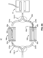
- FIG. 8A is a schematic depiction of a portion of another triple-quadrupole mass spectrometer system 70 that employs a novel switchable branched ion trap apparatus 72 in accordance with the present teachings.
- the system 70 illustrated in FIG. 8A is similar to the system 60 depicted in FIG. 4 except that the ion trap 64 of the latter system is replaced by a switchable branched ion trap apparatus 72.
- the switchable branched ion trap apparatus 72 is disposed between the collision cell 44 and the cooling cell 51 and comprises a pair of curved ion conduits 79a, 79b, either of which may be employed as an ion trap.
- An ion lens 56 may be disposed between the collision cell 44 and an inlet end of the switchable branched ion trap apparatus 72.
- an ion lens 66 may be disposed between an outlet end of the switchable branched ion trap apparatus 72 and the cooling cell 51.
- the structural details of an exemplary embodiment of such a switchable branched ion trap apparatus are discussed further below in reference to FIGS. 9A , 9B , 10A and 10B .
- the switchable branched ion trap apparatus 72 replaces the pair of switchable branched ion guides and pair of ion traps depicted in FIG. 5 , FIG. 6A and FIG. 6B .
- FIG. 8B is a schematic depiction of a portion of another triple-quadrupole mass spectrometer system 80 in accordance with the present teachings.
- the system 80 of FIG. 8B does not include a separate ion cooling cell (such as the ion cooling cell 51 shown in FIG. 8A ).
- the functionality of both the cooling cell and the switchable branched ion trap apparatus is provided by a modified version of the switchable branched ion trap apparatus, which is depicted in FIG. 8B as switchable branched ion trapping and cooling apparatus 74.
- the switchable branched ion trapping and cooling apparatus 74 includes an extended portion, relative to the previously-described apparatus 72, that is disposed within a partially enclosed container 73 into which a suitable inert gas is supplied, through gas supply tube 75. Accordingly, the switchable branched ion trapping and cooling apparatus 74 is partially disposed within the container 73 and partially disposed outside of the container 73. The inert gas is supplied into the container 73 at a pressure that is sufficient to damp the kinetic energy of ions being transported within an outlet conduit of the apparatus 74 but that is insufficient to cause fragmentation of the ions. In this fashion, the extended portion of the apparatus 74 functions as an ion cooling portion of the apparatus.
- the structural details of an exemplary embodiment of such a switchable branched ion trapping and cooling apparatus are described below in reference to FIG. 11 .
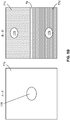
- FIGS. 9A and 9B respectively illustrate a longitudinal cross sectional view and two transverse cross sectional views of a switchable branched ion trap apparatus 72, as may be employed in the system 70, in accordance with the present teachings.
- the apparatus 72 comprises a plurality of apertured thin electrodes or ring electrodes 77a, 77b, 77c, 77d that are configured in a stacked configuration.
- An "apertured thin electrode”, as the term is used herein, is an electrode, preferably but not necessarily in plate or plate-like form, having an aperture, where the smallest diameter of the aperture is greater than the thickness of the electrode or plate.
- the apertured thin electrodes may be disposed, in preferred embodiments, substantially parallel to one another, but such parallelism is not required.
- An insulating or supporting member 76 may be disposed between electrodes 77c and 77d, preferably along the central axis 71 of the apparatus. Additional or alternative insulating or supporting or insulating components (not illustrated for clarity of presentation) may be disposed in the planar gaps between successive electrodes or at the outer edges of electrodes. Additional separate electrodes 77e, 77f may be disposed at the respective ends of the insulating or supporting member 76.
- FIG. 9B which illustrates transverse cross sections along section lines A-A and B-B whose locations are indicated in FIG, 9A , depicts a single apertured thin electrode 77b on the left-hand side and one each of apertured thin electrodes 77c and 77d on the right-hand side.
- Each of the apertured thin electrodes 77b (as well as each of the apertured thin electrodes 77a ) comprises an aperture 178.
- Each of the apertured thin electrodes 77c and 77d comprises an aperture 179.
- the apertured thin electrodes are depicted as rectangular plates in FIG. 9B , the apertured thin electrodes need not be rectangular and need not be in plate form and could comprise any shape that is suitable for mounting in a particular apparatus.
- the apertures 178, 179 are illustrated as elliptical in shape in FIG. 9B , these apertures are not restricted to any particular form and could alternatively be circular in shape or of any other shape. Further, the apertures need not all have the same shape.
- the central axis 71 of the apparatus 72 passes through the apertures 178 of apertured thin electrodes 77a and apertured thin electrodes 77b and, preferably, through the centers of these apertures.
- the apertured thin electrodes 77c and 77d are oppositely disposed with respect to the axis 71 as illustrated in FIG. 9A and FIG. 9B . Therefore, the axis 71 does not pass through the apertures 179 of apertured thin electrodes 77c and 77d.
- the apertures of the electrodes apertured thin electrodes 77c and the apertures of the apertured thin electrodes 77d are diametrically opposed to one another with respect to the axis 71.
- the plurality of apertures 178 of apertured thin electrodes 77a define an inlet ion conduit 78a that is disposed at an inlet end 172a of the apparatus 72 and the plurality of apertures 178 of apertured thin electrodes 77b define an outlet ion conduit 78b that is disposed at an outlet end 172b of the apparatus.
- the plurality of apertures 179 of apertured thin electrodes 77c define a first curved ion trapping conduit 79a and the plurality of apertures 179 of apertured thin electrodes 77d define a second curved ion trapping conduit 79b.
- the curvature of the ion trapping conduits 79a, 79b is caused by the varying displacement of the apertures 179 - either away from or towards the central axis 71 - between each electrode and the successive electrode.
- the apertures 179 and the widths of at least some of the apertures 178 are configured such that the two ion trapping conduits 79a, 79b either converge to or diverge from each of the inlet and outlet ion conduits 78a, 78b.
- the electrodes of the switchable branched ion trap apparatus 72 are electrically coupled to one or more voltage sources that can supply an oscillatory primary RF voltage to the set of apertured thin electrodes such that the instantaneous voltage applied to every successive apertured thin electrode is 180-degrees ( ⁇ radians) out of phase with the voltage applied to the preceding electrode.
- ⁇ radians 180-degrees
- the electrical couplings between the apparatus 72 and the one or more voltage sources are such that the individual DC voltages applied to electrodes may correspond to various DC voltage gradients or voltage profiles and that they may be applied, independently, to each of the set of apertured thin electrodes 77a, the set of apertured thin electrodes 77b, the set of apertured thin electrodes 77c and the set of apertured thin electrodes 77d. Also the DC voltages applied to the apertured thin electrodes 77e and 77f may be switched, independently of one another, so as to conform to a voltage profile applied to either the set of apertured thin electrodes 77c or the set of apertured thin electrodes 77d.
- incoming ions (entering the apparatus 72 at inlet end 172a and passing through inlet ion conduit 78a ) may be deflected to either of the curved ion conduits 79a, 79b and ions may be either independently trapped within or released out of either of the curved ion conduits.
- the electrical couplings between the apparatus and the one or more voltage sources may be such that an auxiliary RF voltage may be superimposed on any other voltages or voltage waveform applied to the set of apertured thin electrodes 77c, or to the set of apertured thin electrodes electrodes 77d, where the auxiliary RF voltage is applied such that the same auxiliary RF phase, same auxiliary RF frequency and same auxiliary RF amplitude is applied to all of the electrodes of each electrode set 77c or 77d generally but not to both electrode sets 77c and 77d at the same time.
- auxiliary RF voltage permits ions to be "leaked" from either of the curved ion trapping conduits to the outlet ion conduit 78b in reverse order of their mass-to-charge ratios, as described further below.
- Such mass-selective release of ions out of the switchable branched ion trap apparatus 72 can be controllably operated such that such a downstream quadrupole mass filter passes each particular m / z range of ions just at the same time that those ions arrive at the quadrupole mass filter after having been released from one of the ion traps.
- the quadrupole mass filter may be scanned so as to pass ions therethrough in reverse order of their mass-to-charge ratios, but such reverse scanning of the mass filter is not a necessity.
- FIGS. 10A and 10B are schematic depictions of a first and a second operational configuration, respectively, of the switchable branched ion trap apparatus 72 of FIGS. 9A and 9B .
- the switchable branched ion trap apparatus 72 is included within a mass spectrometer system, such as the mass spectrometer system 70 schematically shown in FIG. 8A .
- the different operational configurations illustrated in FIGS. 10A and 10B may correspond to alternative pathways by which ions may be routed to the downstream ion cooling cell 51 and then to the quadrupole mass filter 24 within the mass spectrometer system 70.
- the first and second operational configurations of the switchable branched ion trap apparatus 72 correspond to those depicted in FIGS.
- a second ion trap is accumulating ions into a batch or packet of ions so as to average ion abundance fluctuations.
- the ion trapping occurs within the first and second curved ion trapping conduits 79a, 79b.
- Exemplary hypothetical schematic DC voltage profiles over the length of the switchable branched ion trap apparatus 72 are illustrated in the uppermost and lowermost portions of FIGS. 10A and 10B . It is understood that the illustrated DC voltage profiles are superimposed on any other voltages that may be applied to the electrodes, such as oscillatory RF voltages.
- the DC voltage profile 83a in the lowermost portion of each figure is identical to the voltage profile 83a in the uppermost portion of the respective figure, since both profiles pertain to DC voltages applied to aperture electrodes 77a.
- the voltage profiles applied to apertured thin electrodes 77a, apertured thin electrodes 77c and apertured thin electrodes 77d are such that incoming ions are diverted, along solid-line pathway 82a, to curved ion conduit 79a and are prevented from entering curved ion conduit 79b.
- the ions continue to move down an electrical potential gradient at the entrance into curved ion conduit 79a but encounter a DC electrical potential barrier of magnitude V 3 - V 1 at the entrance to curved ion conduit 79b.
- the ions flowing into curved ion conduit 79a reach a potential minimum at some point within the confines of conduit which prevents further flow of these ions into outlet conduit 78b ( FIG. 9A ).
- the ions following pathway 82a in FIG. 10A are trapped in curved ion conduit 79a.
- the accumulation of ions in this fashion averages any short-term random ion abundance fluctuations in an incoming ion stream.
- the DC voltage profiles are illustrated as either sloping lines or curves in FIGS. 10A and 10B , they may be replaced by other forms, such as constant-potential wells, in the portions of the apparatus used for trapping.
- a pair of pseudo-potentials 83e and 83f will be generated at the boundary between electrodes 77a and 77d and at the boundary between electrodes 77d and 77b.
- the first of these pseudo-potentials 83e is produced by the resulting auxiliary RF voltage gradient between electrode set 77a ( FIG. 9A ) and the electrode set 77d ( FIG. 9A ).
- the second of these pseudo potentials 83f is produced by the resulting auxiliary RF voltage gradient between the electrode set 77d and the electrode set 77b.
- pseudo-potentials are represented as shaded areas on top of the segments of the DC voltage profiles.
- the pseudo potential 83e just adds to the effect of DC barrier potential (approximately V 3 - V 1 ) that prevents ions from entering the curved ion conduit 79b.
- the pseudo-potential 83f may act as a barrier preventing ion extraction from the curved ion conduit 79b.
- the portion of the shaded area representing the pseudo-potential 83f that extends higher than voltage V 4 schematically represents the height of this effective potential barrier for a given m / z.
- the height of this potential barrier varies according to mlz ratio since, as generally known, the intensity of pseudo-potentials varies inversely with m / z.
- the present inventors have applied the above finding of controlled release of ions of progressively decreasing m / z to the apparatus 72.
- the pseudo-potential, 83f above voltage V 4 in FIGS. 10A may thus be understood as a schematic representation of the magnitude of the effective barrier preventing release of ions from the curved ion conduit 79b to the outlet ion conduit 78b, where ions of progressively decreasing m / z would experience correspondingly higher pseudo-potential barrier.
- Progressive decreasing of the amplitude of the applied auxiliary RF voltage is represented as a controlled lowering (as indicated by downward pointing arrow 85 ) of the pseudo-potential barrier 83f as the magnitude of the pseudo-potential will vary as the square of magnitude the applied auxiliary RF voltage.
- the extractive voltage gradient imposed by the voltage difference between DC voltage V 4 applied to the last electrode of the electrode set 77d and the DC voltage V 5 applied to the first electrode of the electrode set 77b is sufficient enable ions of progressively lower mlz to transit through the pseudo-potential and pass into and through the curved ion conduit 79b.
- auxiliary RF voltage is applied to all of the electrodes 77d such that all electrodes receive the same amplitude, frequency and phase
- one of ordinary skill in the art may envisage alternative configurations of electrodes and/or associated applied auxiliary RF voltage or a set of auxiliary RF voltages to generate an adjustable pseudo-potential barrier in such a region.
- the mass-selective release of ions of each batch or packet is coordinated with the mass scanning of a downstream quadrupole mass filter such that ions of a given mlz range are released from the ion channel 79b and transit through ion channel 78b at a time such that they will arrive at the entrance of the quadrupole mass filter when the quadrupole mass filter is passing ( m / z selectively transmitting) ions of a similar m / z range.
- Improper coordination of the m / z selective release of ions from ion channel 79b may result in few or no ions within the m / z range being selected by the quadrupole mass filter actually being delivered to it.
- variable DC electrical potential differences between the switchable branched ion trap apparatus 72 and the quadrupole mass filter may be adjustably controlled such that ions pass into and through the quadrupole mass filter at a nominally common velocity of transit, irrespective of their m / z ratio.
- the operation of the apparatus 72 in its second operational configuration is similar to the operation as shown in FIG. 10A , except that the voltage profiles applied to apertured thin electrodes 77c and 77d are reversed from those illustrated in FIG. 10A .
- the voltage profile 83c is applied across the set of electrodes 77d and the voltage profile 83d is applied across the set of electrodes 77c.
- an incoming stream of ions is directed into and trapped within curved ion conduit 79b along ion pathway 82c while, at the same time, an ion batch or packet that was previously trapped within curved ion conduit 79a is released out of that curved ion conduit and out of the apparatus along ion pathway 82d.
- the auxiliary RF voltage if any, is applied to apertured thin electrodes 77c.
- the resulting pseudo-potential barriers at either end of ion conduit 79a are depicted as the shaded regions.
- Extended operation of the apparatus 72 alternates between the two operational configurations illustrated in FIGS. 10A and 10B .
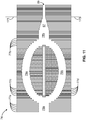
- FIG. 11 illustrates one example of switchable branched ion trapping and cooling apparatus 74 in accordance with some embodiments in accordance with the present teachings.
- the apparatus 74 differs from the previously-described switchable branched ion trap apparatus 72 in that at least a portion of the electrodes 77b comprises a set of apertures that decrease in size in progression towards the outlet end of the apparatus so as to define a funnel-shaped ion outlet conduit portion 87 of the apparatus.
- Another portion of the electrodes 77b disposed further towards the outlet end of the apparatus may comprise a set of apertures of constant size so as to define a reduced-diameter conduit portion 89 between opposing electrodes of the other portion.
- the boundary between the funnel-shaped ion outlet conduit portion 87 and the reduced-diameter conduit portion 89 may align with a wall 173 of the container 73 that receives a supply of inert gas through gas supply tube 75 (see FIG. 8B ).
- the reduced diameter of the reduced-diameter conduit portion 89 may function as an ion cooling portion of the apparatus 74.
- the same reduced-diameter conduit portion may also function as a gas-flow-limiting aperture that limits the flow of damping gas into the curved ion conduits 79a, 79b which are maintained at a lower pressure at (higher vacuum) than the cooling portion of the apparatus.
- the pressure in the curved ion conduits must be sufficiently high to enable efficient trapping and accumulation of injected ions but not so high as to overly extend the time of ion extraction.
- the physical design of apparatus 74 is such that the gas conductances between the cooling portion of the reduced diameter conduit portion 89, the curved ion conduits 79a, 79b and the enclosing high-vacuum chamber (e.g., high-vacuum chamber 23 of FIG. 1 ) and its associated evacuation (pumping) system maintain these pressures for appropriately set damping gas flows through the gas supply tube 75.
Landscapes
- Chemical & Material Sciences (AREA)
- Analytical Chemistry (AREA)
- Electron Tubes For Measurement (AREA)
- Other Investigation Or Analysis Of Materials By Electrical Means (AREA)
Applications Claiming Priority (1)
| Application Number | Priority Date | Filing Date | Title |
|---|---|---|---|
| US15/588,158 US20180323050A1 (en) | 2017-05-05 | 2017-05-05 | Ion integrating and cooling cell for mass spectrometer |
Publications (1)
| Publication Number | Publication Date |
|---|---|
| EP3399541A1 true EP3399541A1 (de) | 2018-11-07 |
Family
ID=62110923
Family Applications (1)
| Application Number | Title | Priority Date | Filing Date |
|---|---|---|---|
| EP18170446.1A Withdrawn EP3399541A1 (de) | 2017-05-05 | 2018-05-02 | Ionenintegrations- und -kühlzelle für massenspektrometer |
Country Status (2)
| Country | Link |
|---|---|
| US (1) | US20180323050A1 (de) |
| EP (1) | EP3399541A1 (de) |
Families Citing this family (11)
| Publication number | Priority date | Publication date | Assignee | Title |
|---|---|---|---|---|
| US12089932B2 (en) | 2018-06-05 | 2024-09-17 | Trace Matters Scientific Llc | Apparatus, system, and method for transferring ions |
| US10840077B2 (en) | 2018-06-05 | 2020-11-17 | Trace Matters Scientific Llc | Reconfigureable sequentially-packed ion (SPION) transfer device |
| US11043370B2 (en) | 2018-07-20 | 2021-06-22 | Battelle Memorial Institute | Device and system for selective ionization and analyte detection and method of using the same |
| US10670561B2 (en) * | 2018-07-20 | 2020-06-02 | Battelle Memorial Institute | Device and system for selective ionization and analyte detection and method of using the same |
| US10665441B2 (en) * | 2018-08-08 | 2020-05-26 | Thermo Finnigan Llc | Methods and apparatus for improved tandem mass spectrometry duty cycle |
| GB2583694B (en) * | 2019-03-14 | 2021-12-29 | Thermo Fisher Scient Bremen Gmbh | Ion trapping scheme with improved mass range |
| US11069519B1 (en) * | 2019-10-25 | 2021-07-20 | Thermo Finnigan Llc | Amplifier amplitude control for a mass spectrometer |
| CN112117173B (zh) * | 2020-09-07 | 2021-06-25 | 华东师范大学 | 一种高效制冷的多极杆冷阱系统 |
| EP4435426A4 (de) * | 2021-11-17 | 2025-03-12 | Shimadzu Corporation | Induktiv gekoppeltes plasmamassenspektrometer |
| US11908675B2 (en) | 2022-02-15 | 2024-02-20 | Perkinelmer Scientific Canada Ulc | Curved ion guides and related systems and methods |
| WO2025235625A1 (en) * | 2024-05-07 | 2025-11-13 | Peninsula Technologies, Llc | Systems and methods for multiplexed mass spectrometry |
Citations (11)
| Publication number | Priority date | Publication date | Assignee | Title |
|---|---|---|---|---|
| US6111250A (en) | 1995-08-11 | 2000-08-29 | Mds Health Group Limited | Quadrupole with axial DC field |
| WO2007010272A2 (en) * | 2005-07-21 | 2007-01-25 | Micromass Uk Limited | Mass spectrometer |
| US7420161B2 (en) | 2006-03-09 | 2008-09-02 | Thermo Finnigan Llc | Branched radio frequency multipole |
| US7459678B2 (en) | 2006-05-12 | 2008-12-02 | Thermo Finnigan Llc | Switchable branched ion guide |
| US20090090853A1 (en) * | 2007-10-05 | 2009-04-09 | Schoen Alan E | Hybrid mass spectrometer with branched ion path and switch |
| US7829850B2 (en) | 2006-03-09 | 2010-11-09 | Thermo Finnigan Llc | Branched radio frequency multipole |
| US20120193526A1 (en) * | 2011-01-31 | 2012-08-02 | Kovtoun Viatcheslav V | Ion Interface Device Having Multiple Confinement Cells and Methods of Use Thereof |
| US8389929B2 (en) | 2010-03-02 | 2013-03-05 | Thermo Finnigan Llc | Quadrupole mass spectrometer with enhanced sensitivity and mass resolving power |
| WO2013092923A2 (en) * | 2011-12-22 | 2013-06-27 | Thermo Fisher Scientific (Bremen) Gmbh | Collision cell for tandem mass spectrometry |
| WO2015185934A1 (en) * | 2014-06-06 | 2015-12-10 | Micromass Uk Limited | Multipath duty cycle enhancement |
| US20160035557A1 (en) * | 2011-11-02 | 2016-02-04 | Micromass Uk Limited | Multi Inlet For Solvent Assisted Inlet Ionisation |
Family Cites Families (1)
| Publication number | Priority date | Publication date | Assignee | Title |
|---|---|---|---|---|
| US6891157B2 (en) * | 2002-05-31 | 2005-05-10 | Micromass Uk Limited | Mass spectrometer |
-
2017
- 2017-05-05 US US15/588,158 patent/US20180323050A1/en not_active Abandoned
-
2018
- 2018-05-02 EP EP18170446.1A patent/EP3399541A1/de not_active Withdrawn
Patent Citations (11)
| Publication number | Priority date | Publication date | Assignee | Title |
|---|---|---|---|---|
| US6111250A (en) | 1995-08-11 | 2000-08-29 | Mds Health Group Limited | Quadrupole with axial DC field |
| WO2007010272A2 (en) * | 2005-07-21 | 2007-01-25 | Micromass Uk Limited | Mass spectrometer |
| US7420161B2 (en) | 2006-03-09 | 2008-09-02 | Thermo Finnigan Llc | Branched radio frequency multipole |
| US7829850B2 (en) | 2006-03-09 | 2010-11-09 | Thermo Finnigan Llc | Branched radio frequency multipole |
| US7459678B2 (en) | 2006-05-12 | 2008-12-02 | Thermo Finnigan Llc | Switchable branched ion guide |
| US20090090853A1 (en) * | 2007-10-05 | 2009-04-09 | Schoen Alan E | Hybrid mass spectrometer with branched ion path and switch |
| US8389929B2 (en) | 2010-03-02 | 2013-03-05 | Thermo Finnigan Llc | Quadrupole mass spectrometer with enhanced sensitivity and mass resolving power |
| US20120193526A1 (en) * | 2011-01-31 | 2012-08-02 | Kovtoun Viatcheslav V | Ion Interface Device Having Multiple Confinement Cells and Methods of Use Thereof |
| US20160035557A1 (en) * | 2011-11-02 | 2016-02-04 | Micromass Uk Limited | Multi Inlet For Solvent Assisted Inlet Ionisation |
| WO2013092923A2 (en) * | 2011-12-22 | 2013-06-27 | Thermo Fisher Scientific (Bremen) Gmbh | Collision cell for tandem mass spectrometry |
| WO2015185934A1 (en) * | 2014-06-06 | 2015-12-10 | Micromass Uk Limited | Multipath duty cycle enhancement |
Non-Patent Citations (3)
| Title |
|---|
| KAISER NATHAN K ET AL: "Controlled Ion Ejection from an External Trap for Extendedm/zRange in FT-ICR Mass Spectrometry", JOURNAL OF THE AMERICAN SOCIETY FOR MASS SPECTROMETRY, ELSEVIER SCIENCE INC, US, vol. 25, no. 6, 2 April 2014 (2014-04-02), pages 943 - 949, XP035315807, ISSN: 1044-0305, [retrieved on 20140402], DOI: 10.1007/S13361-014-0871-6 * |
| KAISER, N.K. ET AL.: "Controlled Ion Ejection from an External Trap for Extended m/z Range in FT-ICR Mass Spectrometry", J. AM. SOC. MASS SPECTROMETRY, vol. 25, no. 6, 2014, pages 943 - 949 |
| KAISER, N.K. ET AL.: "Controlled Ion Ejection from an External Trap for Extended mlz Range in FT-ICR Mass Spectrometry", J. AM. SOC. MASS SPECTROMETRY, vol. 25, no. 6, 2014, pages 943 - 949 |
Also Published As
| Publication number | Publication date |
|---|---|
| US20180323050A1 (en) | 2018-11-08 |
Similar Documents
| Publication | Publication Date | Title |
|---|---|---|
| EP3399541A1 (de) | Ionenintegrations- und -kühlzelle für massenspektrometer | |
| US7034292B1 (en) | Mass spectrometry with segmented RF multiple ion guides in various pressure regions | |
| US6403952B2 (en) | Ion transfer from multipole ion guides into multipole ion guides and ion traps | |
| US7888635B2 (en) | Ion funnel ion trap and process | |
| US6188066B1 (en) | Multipole ion guide for mass spectrometry | |
| CA2448335C (en) | Atmospheric and vacuum pressure maldi ion source | |
| CA2636821C (en) | Concentrating mass spectrometer ion guide, spectrometer and method | |
| CN104126116B (zh) | 用于离子迁移谱的设备和方法 | |
| US9117646B2 (en) | Method and apparatus for a combined linear ion trap and quadrupole mass filter | |
| EP2774168B1 (de) | Ionengrenzflächenvorrichtung mit mehreren begrenzungszellen und verfahren zu ihrer verwendung | |
| US9123517B2 (en) | Ion guide with different order multipolar field order distributions across like segments | |
| WO2010014077A1 (en) | Method and apparatus for ion manipulation using mesh in a radio frequency field | |
| US11270877B2 (en) | Multipole ion guide | |
| US10395914B2 (en) | Efficient ion trapping | |
| US8309911B2 (en) | Methods and apparatus for filling an ion detector cell | |
| CA2487136C (en) | Mass spectrometry with segmented rf multiple ion guides in various pressure regions | |
| CN111696846B (zh) | 质量范围改进的离子俘获方案 | |
| US20250218761A1 (en) | Method of mass spectrometry, a method of manipulating ions using an ion store, an ion store, a mass spectrometer and computer software | |
| CN117642838A (zh) | 用于将离子注入到静电线性离子阱中的方法和系统 |
Legal Events
| Date | Code | Title | Description |
|---|---|---|---|
| PUAI | Public reference made under article 153(3) epc to a published international application that has entered the european phase |
Free format text: ORIGINAL CODE: 0009012 |
|
| STAA | Information on the status of an ep patent application or granted ep patent |
Free format text: STATUS: THE APPLICATION HAS BEEN PUBLISHED |
|
| AK | Designated contracting states |
Kind code of ref document: A1 Designated state(s): AL AT BE BG CH CY CZ DE DK EE ES FI FR GB GR HR HU IE IS IT LI LT LU LV MC MK MT NL NO PL PT RO RS SE SI SK SM TR |
|
| AX | Request for extension of the european patent |
Extension state: BA ME |
|
| STAA | Information on the status of an ep patent application or granted ep patent |
Free format text: STATUS: REQUEST FOR EXAMINATION WAS MADE |
|
| 17P | Request for examination filed |
Effective date: 20190507 |
|
| RBV | Designated contracting states (corrected) |
Designated state(s): AL AT BE BG CH CY CZ DE DK EE ES FI FR GB GR HR HU IE IS IT LI LT LU LV MC MK MT NL NO PL PT RO RS SE SI SK SM TR |
|
| STAA | Information on the status of an ep patent application or granted ep patent |
Free format text: STATUS: EXAMINATION IS IN PROGRESS |
|
| 17Q | First examination report despatched |
Effective date: 20210630 |
|
| STAA | Information on the status of an ep patent application or granted ep patent |
Free format text: STATUS: THE APPLICATION IS DEEMED TO BE WITHDRAWN |
|
| 18D | Application deemed to be withdrawn |
Effective date: 20211111 |