EP3399599B1 - Connecteur enfichable, fiche et système de connecteur enfichable - Google Patents
Connecteur enfichable, fiche et système de connecteur enfichable Download PDFInfo
- Publication number
- EP3399599B1 EP3399599B1 EP18000234.7A EP18000234A EP3399599B1 EP 3399599 B1 EP3399599 B1 EP 3399599B1 EP 18000234 A EP18000234 A EP 18000234A EP 3399599 B1 EP3399599 B1 EP 3399599B1
- Authority
- EP
- European Patent Office
- Prior art keywords
- plug
- lance
- configuration
- sleeve
- plug connector
- Prior art date
- Legal status (The legal status is an assumption and is not a legal conclusion. Google has not performed a legal analysis and makes no representation as to the accuracy of the status listed.)
- Active
Links
Images


Classifications
-
- H—ELECTRICITY
- H01—ELECTRIC ELEMENTS
- H01R—ELECTRICALLY-CONDUCTIVE CONNECTIONS; STRUCTURAL ASSOCIATIONS OF A PLURALITY OF MUTUALLY-INSULATED ELECTRICAL CONNECTING ELEMENTS; COUPLING DEVICES; CURRENT COLLECTORS
- H01R13/00—Details of coupling devices of the kinds covered by groups H01R12/70 or H01R24/00 - H01R33/00
- H01R13/62—Means for facilitating engagement or disengagement of coupling parts or for holding them in engagement
- H01R13/627—Snap or like fastening
- H01R13/6275—Latching arms not integral with the housing
-
- H—ELECTRICITY
- H01—ELECTRIC ELEMENTS
- H01R—ELECTRICALLY-CONDUCTIVE CONNECTIONS; STRUCTURAL ASSOCIATIONS OF A PLURALITY OF MUTUALLY-INSULATED ELECTRICAL CONNECTING ELEMENTS; COUPLING DEVICES; CURRENT COLLECTORS
- H01R13/00—Details of coupling devices of the kinds covered by groups H01R12/70 or H01R24/00 - H01R33/00
- H01R13/62—Means for facilitating engagement or disengagement of coupling parts or for holding them in engagement
- H01R13/627—Snap or like fastening
- H01R13/6277—Snap or like fastening comprising annular latching means, e.g. ring snapping in an annular groove
-
- H—ELECTRICITY
- H01—ELECTRIC ELEMENTS
- H01R—ELECTRICALLY-CONDUCTIVE CONNECTIONS; STRUCTURAL ASSOCIATIONS OF A PLURALITY OF MUTUALLY-INSULATED ELECTRICAL CONNECTING ELEMENTS; COUPLING DEVICES; CURRENT COLLECTORS
- H01R13/00—Details of coupling devices of the kinds covered by groups H01R12/70 or H01R24/00 - H01R33/00
- H01R13/62—Means for facilitating engagement or disengagement of coupling parts or for holding them in engagement
- H01R13/639—Additional means for holding or locking coupling parts together, after engagement, e.g. separate keylock, retainer strap
-
- H—ELECTRICITY
- H01—ELECTRIC ELEMENTS
- H01R—ELECTRICALLY-CONDUCTIVE CONNECTIONS; STRUCTURAL ASSOCIATIONS OF A PLURALITY OF MUTUALLY-INSULATED ELECTRICAL CONNECTING ELEMENTS; COUPLING DEVICES; CURRENT COLLECTORS
- H01R13/00—Details of coupling devices of the kinds covered by groups H01R12/70 or H01R24/00 - H01R33/00
- H01R13/46—Bases; Cases
- H01R13/502—Bases; Cases composed of different pieces
- H01R13/506—Bases; Cases composed of different pieces assembled by snap action of the parts
Definitions
- the invention relates to a connector system comprising a connector, in particular a push-pull connector, and a plug for such a connector.
- connector systems for separating or connecting two line sections which are formed for carrying an electrical current and / or for transmitting electronic signals.
- the individual connectors of these connector systems have connecting sections which can be coupled by means of a form fit and / or a force fit and which, in particular when used in devices that require the connection to be secured against unintentional loosening, such as when used in industrial systems or in a motor vehicle, by means of a screw connection can be secured.
- push-pull connector systems in which the connector system is coupled without the provision of a thread or a nut. The problem is that only one of the different types of systems can be used in each case, since the conventional connector systems are incompatible with one another.
- EP 1 115 179 A2 discloses a multi-toothed locking ring for a rotary coupling system which traverses a thread of a complementary half of the rotary coupling system in the axial direction and engages on the external thread of the complementary half.
- EP 0 881 713 A1 discloses a lockable electrical connector having at least one contact-carrying first part and at least one contact-carrying second part, each part having a housing in which the corresponding contact is held by insulating material, the housing of the second part on the housing of the first Part can be plugged in and to lock the second part on the first part at the end of the mating process, the housing of the two parts carries a movable ring.
- EP 1 672 751 A1 discloses a socket for compact fluorescent lamps with bases of the types G23 or G24 with a socket housing part made of insulating material containing electrical contacts, with locking springs arranged in the socket housing part engaging behind the locking lugs present on the lamp socket for locking the lamp socket.
- the object of the present invention is to provide an improved connector, a plug for such a connector and a connector system.
- a connector system according to claim 1 is provided.
- the connector according to the invention is suitable for separating or connecting two current-carrying line sections in devices that require the use of vibration-proof connections or connections secured against unintentional loosening during operation of the device due to vibrations and / or frequent relative movements of individual components against each other, and which nevertheless quickly and should be easy to solve.
- plug connectors and / or plugs can have a connection contact.
- the plug connector and / or the plug can have an insulating body or a plug insulating body, in which the connection contacts can be arranged.
- the insulation body or plug insulation body can have a plurality of essentially cylindrical insulation body recesses which extend in the axial direction through the insulation body or plug insulation body.
- the connection contacts which can each have a stranded wire connection section, can be arranged in the insulation body recesses.
- the strand connection sections can each be connectable to the electrical lines or the individual strands of a respectively assigned electrically conductive cable.
- the strand connection sections are each connected to an associated strand, for example by soldering or clamping the strand to the strand connection section.
- the number of connection contacts of a connector or plug is not limited, and can be, for example, 2 to 8 or more.
- connection contacts also each have a contacting section, wherein the contacting section can be designed as a female or a male variant.
- the connection contacts of the plug are preferably each formed as a male contact section, the male contact section being designed in such a way that it can be inserted into a female contact section.
- the connection contacts of the plug connector are preferably each formed as a female contacting section, the female contacting section being designed such that it can accommodate a complementary male contacting section.
- the female connector can also be referred to as a socket. If contact is established between the preferably male contacting sections of the plug and the preferably female contacting sections of the plug connector, the plug and the plug connector are connected in an electrically conductive manner.
- the male contacting sections of the complementary plug are pushed in a plugging direction into the female contacting sections of the plug connector, the plugging direction resulting from a directed movement of the plug and plug connector along their axial extent to one another.
- the receiving area of the connector can in particular be defined by the movable sleeve element and the at least one lance, the sleeve element at least partially enclosing the lance.
- the sleeve element can be movable in the axial and / or in the radial direction relative to the lance. Instead of a single lance, a plurality of lances can be provided which are at least partially enclosed by the sleeve element.
- the lance extends with its longitudinal dimension along the longitudinal axis of the sleeve element and has a latching hook which can undercut a holding configuration formed on the complementary plug in such a way that the Connection of connector and plug is held positively in the plug position.
- the latching hook can extend at least radially inward from the lance, the holding configuration of the plug then extending radially outward from the plug, so that the latching hook can undercut the holding configuration.
- the term undercutting can in principle also mean reaching behind or hooking or hooking behind. In other words, the terms “undercut”, “gripping behind”, “rear hook” or “hooking in” can be used synonymously in this application.
- the plug can have several holding configurations, in particular one per lance.
- the latching hook of the lance and / or the holding configuration of the plug can each be formed with a slope so that the latching hook can slide past the holding configuration with little resistance during an insertion movement.
- the lance is elastically displaceable in particular while the latching hook slides past the holding configuration and springs back after sliding past, as a result of which the latching hook can latch in a form-fitting manner behind the holding configuration. Since the lance can be moved outwards, various external profiles can be formed on the plug without hindering the connection of the plug connector and plug.
- the sleeve element can have a lifting configuration per lance, which can interact with a displacement configuration formed on each lance such that the lance can be displaced radially outward when the sleeve element moves relative to the lance.
- the radial displacement here means a movement of the lance in a radial direction, that is to say along an imaginary axis of symmetry through the connector that extends orthogonally to the length.
- the term “outward” denotes the direction of movement of the lance during the elastic displacement in relation to the receiving area, viewed in a radial cross section, the receiving area representing an inner area. So the lance shifts in Outward direction, away from the shooting area.
- the sleeve element can be moved relative to the lance in such a way that the lifting configuration of the sleeve element is approximately congruent with the displacement configuration of the lance, whereby the lance is displaced elastically outward in the radial direction.
- the displacement configuration and / or the lifting configuration can each have a slope. As a result, the displacement configuration and the lifting configuration slide with a relative movement along the inclines and the relative movement can be carried out with little and approximately constant expenditure of force.
- the plug is free of the form-fitting connection between the locking hook of the lance and the holding configuration of the plug and the connection area of the plug can be pulled out of the receiving area of the plug connector, whereby the electrically conductive connection can be separated.
- At least one limiting section can also be formed on the connector, which limits a relative movement of the sleeve element to the lance in such a way that, during the relative movement, the lifting configuration of the sleeve element cannot be moved beyond a provided position on or beyond the displacement configuration of the lance.
- the relative movement of the sleeve element can, depending on the embodiment, take place either in the axial direction relative to the lance or in a radial rotary movement relative to the lance.
- the bevels on the displacement configuration of the lance and / or on the lifting configuration of the sleeve element can be provided in accordance with the intended relative movement.
- the sleeve element is preferably essentially cylindrical and extends coaxially with the plug connector or the insulation body.
- the sleeve element can be coupled to the plug connector or the insulation body via the lance or the lances, in particular it can be coupled to the plug connector or the insulation body exclusively via the lance or the lances.
- the sleeve element has a sleeve ring lying radially on the inside and the lifting configuration is formed on the sleeve ring.
- the sleeve ring of the sleeve element can advantageously be manufactured inexpensively by means of various manufacturing processes.
- the sleeve element can be formed in one piece with the sleeve ring by means of an injection molding process, or the sleeve element and sleeve ring are formed in several pieces, with the sleeve element being connected to the sleeve ring by subsequent joining, for example by gluing, pressing or welding.
- the sleeve element formed in this way with a radially inner sleeve ring moves the sleeve ring and thus the lifting configuration when the sleeve element moves relative to the lance, whereby the lifting configuration can engage the displacement configuration when the sleeve element moves relative to the lance.
- the sleeve ring preferably has at least one recess, and the lance extends through the recess in such a way that the lifting configuration is arranged radially on the inside of the lance, and by means of a relative movement of the sleeve element to the lance, the lifting configuration engages with the displacement configuration, whereby the lance is elastically displaceable radially outward.
- the recess can be formed on the sleeve ring radially on the outside and open radially outwards, whereby the lance can be displaced elastically radially outwards. This ensures that the lance can be displaced without hindrance will.
- the sleeve ring can otherwise be connected to the sleeve element at the remaining sections.
- the number of recesses in the sleeve ring can correspond to the number of lances, with one lance each being able to be arranged in a recess.
- the latching hooks of the plurality of lances can be released simultaneously from the holding configurations of the plug, whereby the plug can be unlocked and removed in one working step.
- the sleeve element and the sleeve ring are preferably separate components.
- the sleeve ring can be arranged in the sleeve element.
- the sleeve element and the sleeve ring can each be formed as one-piece components.
- the sleeve element and the sleeve ring can also be designed as a multi-part component. If the sleeve ring is arranged in the sleeve element, a two-part sleeve assembly is formed. In particular, casting, milling or injection molding can be used as a method for producing the sleeve element and the sleeve ring.
- the latching hook and the displacement configuration preferably point in the same radial direction. Consequently, the latching hook and the displacement configuration can point either together or at the same time in the radial direction inward or in the radial direction outward.
- the sleeve element can have at least one radially inwardly deformed lance passage area, the lance passage area extending in the axial direction along a section of the sleeve element, and wherein the lance passage area has a recess and the lance thus extends through the recess along the radially inwardly deformed lance passage area that the lifting configuration is arranged radially on the inside of the lance, and by means of a relative movement of the Sleeve element for the lance, the lifting configuration engages with the displacement configuration, whereby the lance is elastically displaceable radially outward.
- the radially inwardly deformed lance passage area of the sleeve element can extend in some areas in the direction of the longitudinal axis of the sleeve element and have a depth at which the lance can extend from the passage of the lance through the recess along the radially inwardly deformed lance passage area.
- the lifting configuration can be formed on a suitable section of the lance passage area as a structure extending radially outward from the sleeve element or the lance passage area.
- the suitable section means in particular the section of the lance passage area which is located in the axial direction, i.e. in the direction of the longitudinal axis of the sleeve element, approximately at the level of the displacement configuration of the lance.
- the displacement configuration can point or protrude inward in the radial direction.
- the lifting configuration can come into engagement with the displacement configuration, whereby the lance can be displaced elastically radially outward.
- the sleeve element can also be produced in this way without the provision of a sleeve ring, the lifting configuration being formed in a cost-effective manner by providing the inwardly deformed lance passage area with the recess.
- the connector preferably has a plurality of lances, the lances being formed on a carrier element and the displacement configurations of the lances in each case interacting with the lifting configuration of the sleeve elements in such a way that when the sleeve element moves relative to the plurality of lances, the lances simultaneously radially outward are elastically displaceable.
- the carrier element can be ring-shaped and / or sleeve-shaped and forms the base for the lance or preferably the plurality of lances.
- the lances extend axially forward in a starting from the carrier element Insertion direction of the connector, which runs opposite to an insertion direction of the connector.
- a plurality of lances can be produced in one piece together with the carrier element, for example as a turned part or by means of an injection molding process, which results in inexpensive production and simple assembly in the connector.
- the carrier element for example as a turned part or by means of an injection molding process, which results in inexpensive production and simple assembly in the connector.
- no further supports for the majority of lances need to be provided on the connector.
- the lances are preferably spaced apart from one another at regular angular intervals.
- the receptacle area of the connector is formed with a uniform distribution of lances, so that when the connector is electrically connected to the complementary plug, insufficient electrical contact between individual, complementary connection contacts of the plug connector and plug is avoided.
- the latching hook and the displacement configuration preferably extend radially inward from the lance.
- the lance can be elastically displaced radially outward, whereby the positive connection between the latching hook and the holding configuration can be released by means of one work step, the connector having a smooth profile on the outside.
- the connector therefore advantageously takes up little space.
- the latching hook and / or the displacement configuration preferably have an inclined section.
- the lance therefore slides advantageously with little resistance along the lifting configuration of the sleeve element and along the holding configuration of the plug, overcoming the elastic deformation of the Lance, whereby the plug can be connected to the connector without great effort.
- a plug for the connector system wherein the plug has a connection area with a thread and a holding configuration, and wherein the thread has at least one axially extending lowered area, wherein on the rear portion of the connector in the plugging direction of the lowered area, the holding configuration is formed, wherein in a plugged position of the plug and the connector the lance is arranged in the lowered area such that the holding configuration of the plug is undercut by the latching hook of the at least one lance.
- the plug can have a plug insulation body, wherein the plug insulation body can have a plurality of essentially cylindrical insulation body recesses which extend in the axial direction through the plug insulation body. Terminal contacts can be arranged in the insulation body recesses, each of which has a strand connection section.
- the strand connection sections can each be connectable to the electrical lines or the individual strands of a respectively assigned electrically conductive cable. In order to produce such an electrically conductive connection, the strand connection sections can each be connected to an associated strand, for example by soldering or clamping the strand to the strand connection section.
- connection contacts also each have a contacting section, wherein the contacting section can be designed as a female or a male variant.
- the connection contacts of the plug are preferably each formed as a male contacting section, the male contacting section being designed such that it can be inserted into the preferably female contacting section of the plug connector.
- the thread of the plug can have a plurality of recessed areas, which can be approximately strip-shaped, the recessed areas extending from the holding configuration, starting in the plugging direction or in the axial direction.
- the recessed areas can be produced, for example, by means of milling and can be designed as a flattened residual thread or completely without a thread.
- the lowered areas can also be referred to as thread recesses.
- the recessed areas can be formed along the periphery of the connection area in the areas which, in the mating position, correspond to the areas of the lances and the lifting configurations of the connector.
- the plug preferably has three recessed areas. The lowered areas can have different widths in the circumferential direction.
- a lowered area can be wider in the circumferential direction, while the other lowered areas have a — preferably identical — narrow dimension in the circumferential direction.
- the wider, recessed area can serve as a visual orientation aid which, in order to connect correctly to the connector, must be aligned with an orientation marking or orientation recess of the connector.
- one of the lances and / or the lifting configurations of the plug connector can be made wider in the circumferential direction than the remaining lances or lifting configurations, so that the plug can only be inserted into the plug connector correctly aligned with the plug connector.
- the plug With correct alignment, the plug can be guided in its plugging movement towards the plug connector through the interaction of the lowered areas with the lances or lifting configurations to the plugging position before it reaches the plugging position.
- the lowered area or the lowered areas are flanked, in particular, in the circumferential direction by threaded sections.
- the threaded sections allow the connector to be screwed to the connector by means of a fastening nut.
- the plug for arranging a plurality of lances can have a plurality of lowered areas or threaded sections, the plug can be screwed into a conventional complementary screw connector with an internal thread by means of the thread.
- the plug is therefore advantageous both for conventional connectors with an internal thread and for the Connector according to one aspect of the present invention is provided.
- the thread preferably has a plurality of depressed areas, and one depressed area has a dimension that is wider in the circumferential direction than the other depressed areas.
- a plug-in movement from the plug into the plug-in connector can position from plug-to-plug connector from the first contact from Snap hooks or lifting configuration to the lowered area.
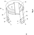
- Fig. 1 shows a perspective exploded view of a plug connector 10 according to an embodiment, comprising a cable 12 with in the present case five strands 14 thereof.
- the cable 12 or the strands 14 are formed for carrying an electrical current and / or for transmitting electronic signals.
- the strands 14 are each connected to a strand connection section of a connection contact AK of an insulation body 16, the insulation body 16 having a plurality of the connection contacts AK.
- the insulation body 16 has a plurality of essentially cylindrical insulation body recesses which extend in the axial direction through the insulation body.
- the connection contacts AK are arranged in each of these insulation body recesses.
- the insulation body 16 has five connection contacts AK, which can each be contacted via the end faces 20a, 20b.
- the insulation body 16 essentially has a cylindrical shape and is formed from a non-conductive material, in the present case from thermoplastic polyurethane (TPU).
- TPU thermoplastic polyurethane
- the insulation body 16 can, however, also be formed from another suitable plastic.
- the connection of the individual strands 14 to the respective strand connection section is formed in the present case by means of soldering.
- the protective sleeve 26 is connected to the end section 22 and the rear end section 24 by means of extrusion coating, wherein this extrusion coating can be the last work step in the assembly of the connector 10.
- the protective sleeve 26 is formed from a non-conductive material, in the present case from thermoplastic polyurethane (TPU).
- TPU thermoplastic polyurethane
- the cable 12 or the strands 14 thereof are connected with the non-free end to an electronic component or an electronic device.
- On the insulation body 16 is between the Face 20a and face 20b a flange ring 28 is formed on the insulation body 16 is between the Face 20a and face 20b a flange ring 28 is formed.
- the flange ring 28 is approximately in the middle between the two end faces 20a, 20b, but at a distance from the rear end section 24 or from the protective sleeve 26 (see FIG Fig. 3 ), arranged.
- the plug connector 10 further has a carrier element 30, the carrier element 30 being pushed in the axial direction 18 from the end face 20b onto the insulation body 16.
- the carrier element 30 is formed as a carrier ring 32 with a carrier wall 34 lying radially on the outside of the carrier ring 32 (see also FIG Fig. 4 ).
- the arrow 36 shows the radial direction, the center of an area enclosed by the carrier ring 32 representing the innermost point when viewed in a radial plan view.
- the carrier ring 32 has a centrally arranged opening that fits precisely to the rear end section 24 and is connected to an end face of the flange ring 28 by means of a joining process, in this case pressing, with an end face facing the flange ring 28, the end face of the flange ring 28 being that face , which in turn faces the carrier ring 32.
- a plurality of lances 38 is formed on the support wall 34 of the support element 30, more precisely it is three lances 38.
- the support element 30 is produced in one piece as a turned part.
- the lances 38 extend axially from the support wall 34 in the plug-in direction of the plug connector SR SV and are arranged radially on the outside of the support ring 32, whereby the lances are spaced apart from the insulation body 16 by the radial width of the support ring 32.
- the lances 38 are also spaced apart from one another on the carrier ring 32 by the same angular distance, in the present case 120 degrees.
- the carrier element 30 is made of a metal such as brass or a spring steel.
- the lances 38 are elastically displaceable radially outward and each have a latching hook 40 and a displacement configuration 42.
- the locking hook 40 and the displacement configuration 42 are rigid and essentially non-elastically deformable.
- the latching hook 40 and the displacement configuration 42 extend radially inward from the lance 38 and each have a ramp-like shape with a slope S.
- the latching hook 40 is formed for undercutting an associated holding configuration 44, likewise including a bevel S, of a complementary plug 46 (see FIG Fig. 7 and 8th ), whereby in a plug-in position of the complementary plug 46 with the plug connector 10, the plug connector system, which comprises the plug 46 and the plug connector 10, is in the present case positively connected.
- the plug 46 and plug connector 10 are pushed together in the axial direction 18, the bevels S of the latching hook 40 and the holding configuration 44 being able to slide on one another, whereby the lance 38 can be displaced elastically radially outward.
- the latching hook 40 has passed the incline S of the holding configuration 44, the lance 38 moves back into the original position and the latching hook 40 latches behind the holding configuration 44.
- the carrier element 30 is surrounded by a sleeve element 48, the sleeve element 48 being essentially formed as a hollow cylinder, the longitudinal extent of which is arranged along the axial direction 18.
- the sleeve element 48 consequently also surrounds the region of the insulation body 16 which is surrounded by the carrier element 30.
- the sleeve element is produced from zinc by means of a die-casting process and has, in sections, a circumferential corrugation R, on which the sleeve element 48 can be gripped in a non-slip manner.
- the corrugation R can be formed from a rubber coating arranged on the sleeve element 48.
- the corrugation R also has an orientation recess which enables the plug to be placed on the connector in a precisely positioned manner.
- a sleeve ring 50 is formed on the sleeve element 48 radially on the inside and essentially at the end (see also Fig. 6 and 8th ).
- the sleeve element 48 and the sleeve ring 50 form a sleeve assembly 64 (see Fig. 6 ).
- the sleeve ring 50 is made as a separate component, ie as an independent component by means of an injection molding process from a plastic or by means of machining from a metal and pressed with the hollow cylinder by means of press fitting.
- the sleeve ring 50 in the present case has three lifting configurations 52, one lifting configuration 52 per lance 38.
- the lifting configuration 52 is formed as a recessed section of the sleeve ring 50 and can each come into engagement with the displacement configuration 42 of an associated lance 38.
- the sleeve ring 50 is formed in the area of the lifting configuration 52 with a recess 54, in which the lance 38 is arranged with an intermediate lance section L arranged between the latching hook 40 and the displacement configuration 42, whereby the lifting configuration 52 is arranged radially on the inside of the lance 38.
- the sleeve element 48 and the sleeve ring 50 formed thereon are movable in the axial direction 18 relative to the lance 38, so that by means of a relative movement of the sleeve element 48 or the sleeve assembly 64 to the lance 38 in the plug-in direction of the plug SR S, the lifting configuration 52 with the displacement configuration 42 in Engagement occurs, whereby the lance 38 is elastically displaced radially outward.
- a distance A is provided between the protective sleeve 26 and the flange ring 28 or the carrier ring 32 arranged on the flange ring 28 (see Fig. 3 ).
- the sleeve element 48 can also be designed with a shape that can surround the protective sleeve 26, so that no distance A has to be provided.
- the engagement between the lifting configuration 52 and the displacement configuration 42 takes place in such a way that due to the axial relative movement of the sleeve element 48 or the sleeve assembly 64 to the lance 38, the lifting configuration 52 slides along the slope S of the displacement configuration 42 and thereby the lance 38 slides radially outward relocated.
- the sleeve element is radial in the insertion direction SR SV expanding inside
- the lifting configuration 52 slides back along the displacement configuration 42 into the original position, namely to the position at which the lance intermediate section L is arranged between the latching hook 40 and the displacement configuration 42 is, whereby the lance 38 is no longer displaced.
- the carrier element 30 is designed with three lances 38 and the sleeve ring 50 has three recesses 54 or three lifting configurations 52, ie one per lance 38, the relative movement of the sleeve element 48 or the sleeve assembly 64 to the lance 38 in the direction of the end face 20b, all three lances 38 can be elastically displaced radially outward at the same time. As a result, a hook behind the holding configurations 44 of the complementary plug 46 can be released by the latching hook 40 of the lance 38, as a result of which the plug 46 can be separated from the plug connector 10.
- the plug connector is formed as a female part of the plug connector system, ie the plug connector has the female connection contacts AK, which are formed for receiving the male connection contacts of the plug 46.
- the connector 10 can also be designed as a male part of the connector system.
- a molded seal 56 is arranged on an area of the flange ring 28, which ensures a flush connection between the plug 46 and the plug connector 10.
- Fig. 2 shows the assembled state of the plug connector 10 in a perspective view.
- the connection contacts AK which are formed to accommodate the current-carrying connection contacts of the plug 46, are arranged on the end face 20a of the insulating body 16.
- Fig. 3 shows a side view of the connector 10, from which the arrangement of the sleeve element 48 in relation to the protective sleeve 26 with a distance A can be seen.
- the sleeve element 48 is for unlocking a connection between plug 46 and plug connector 10 (not shown here) in the direction of the protective sleeve 26 displaceable by the distance A, as a result of which the lances 38 enclosed by the sleeve element 48 can move elastically radially outward, so that a rear hook of the holding configuration 44 of the plug 46 can be released by the latching hook 40 in the plug-in position.
- the corrugation R is used for comfortable and slip-proof gripping of the protective sleeve.
- Fig. 4 shows in detail the carrier element 30 on whose carrier wall 34 the lances 38 are formed.
- the latching hooks 40 and the displacement configurations 42 are formed on the end section in the insertion direction SR SV of the lances 38 (see FIG Fig. 1 ).
- the lance intermediate section L on which the lifting configuration 52 and the recess 54 of the sleeve ring 50 are arranged lies between the latching hooks 40 and the displacement configurations 42.
- the locking hooks 40 and the displacement configurations 42 each have the slope S, the slope S of the locking hook not having to run at the same angle to the lance 38 as the slope S of the displacement configurations 42.
- the respective slopes of different embodiments can be different.
- Fig. 5 shows the carrier element 30 with the sleeve ring 50 arranged thereon, the sleeve ring 50 with the lifting configuration 52 being arranged in the area of the lance intermediate section L.
- the lances 38 are in a non-displaced state. If the sleeve ring 50 is displaced in the insertion direction SR S by means of a movement of the sleeve element 48 (see FIG Fig. 1 ), the lifting configurations 52 each press on the slope S of the displacement configurations 42 (see FIG Fig. 4 , here covered by the lifting configuration 52), whereby the lances 38 are increasingly elastically displaced radially outward. If the lifting configuration 52 glides back along the bevels S to the intermediate lance sections L, the lances shift back into their original position.
- FIG. 14 is a perspective view of the sleeve assembly 64, with FIG In the present embodiment, the sleeve assembly 64 comprises the sleeve element 48 and the sleeve ring 50.
- the sleeve ring 50 has a recess 54 in each of its lifting configurations 52, whereby the lifting configuration 52 is spaced from the hollow cylindrical body of the sleeve element 48 such that the lance 38 can be arranged between the sleeve element 48 and the lifting configuration 52.
- the number of recesses 54 corresponds in the present case to the number of lances 38, namely three.
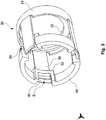
- Fig. 7 shows a perspective view of a plug 46.
- the plug 46 is formed in the present case as a male connector, ie the plug 46 is formed with its male connection contacts for insertion into the female connection contacts AK of the connector 10, and has a cable (not shown) with five in the present case Line contacts or strands (not shown) thereof.
- the cable or the strands are formed for carrying an electrical current and / or transmitting electronic signals.
- the strands are each connected to a connection contact (not shown) of a plug insulation body (not shown).
- the plug insulation body essentially has a cylindrical shape and is made of a non-conductive material, in this case thermoplastic polyurethane (TPU).
- TPU thermoplastic polyurethane
- the plug 46 has a radially outer thread 58, the thread 58 having a plurality of axially extending lowered areas 60, a holding configuration 44 also being formed on the rear sections of the lowered areas 60 in the plug-in direction of the plug connector 10.
- lances 38 extend along lowered areas 60 up to holding configuration 44 and undercut holding configuration 44 with latching hooks 40.
- a lowered area 60 is provided on plug 46 for each lance 38 .
- the lowered areas 60 can be produced by milling out the thread 58.
- the holding configuration 44 has a bevel S on which the bevel S of the latching hook 40 can slide, as a result of which the lance 38 is elastically displaced radially outward until the latching hook 40 engages behind the holding configuration 44 and undercuts the holding configuration 44.
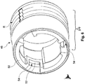
- Fig. 8 shows the connector system comprising the plug 46 and the plug connector 10 in the separated state, the arrow 62 showing the plug direction in which the plug 46 can be pushed into the plug connector to establish an electrically conductive connection.
Landscapes
- Connector Housings Or Holding Contact Members (AREA)
- Details Of Connecting Devices For Male And Female Coupling (AREA)
Claims (9)
- Système de connecteur enfichable présentant un connecteur enfichable (10), en particulier un connecteur enfichable push-pull, comprenant une zone de réception destinée à recevoir une zone de connexion d'une fiche complémentaire (46),
dans lequel le connecteur enfichable (10) présente au moins une languette (38) et un élément de douille (48) déplaçable par rapport à la languette (38),
dans lequel l'élément de douille (48) entoure essentiellement la zone de réception et au moins partiellement la languette (38),
dans lequel un crochet d'encliquetage (40) pour la contre-dépouille d'une configuration de maintien (44) de la fiche complémentaire (46) et une configuration de déplacement (42) sont formés sur la languette (38),
dans lequel l'élément de douille (48) présente au moins une configuration de levage (52) et la configuration de levage (52) coopère de telle façon avec la configuration de déplacement (42), que lors d'un déplacement de l'élément de douille (48) par rapport à la languette (38), la languette (38) peut être déplacée de façon élastique radialement vers l'extérieur,
caractérisé en ce que- l'élément de douille (48) présente une bague de douille (50) s'étendant radialement à l'intérieur et dans lequel l'au moins une configuration de levage (52) est formée sur la bague de douille (50). - Système de connecteur enfichable selon la revendication 1, dans lequel la bague de douille (50) présente au moins un évidement (54), et
dans lequel la languette (38) s'étend de telle façon à travers l'évidement (54), que la configuration de levage (52) est disposée radialement à l'intérieur par rapport à la languette (38), et la configuration de levage (52) vient en prise avec la configuration de déplacement (42) par un mouvement relatif de l'élément de douille (48) par rapport à la languette (38), moyennant quoi la languette (38) peut être déplacée de façon élastique radialement vers l'extérieur. - Système de connecteur enfichable selon la revendication 1 ou 2, dans lequel l'élément de douille (48) et la bague de douille (50) sont des pièces séparées et la bague de douille (50) peut être disposée dans l'élément de douille (48).
- Système de connecteur enfichable selon l'une des revendications 1 à 3, dans lequel le crochet d'encliquetage (40) et la configuration de déplacement (42) sont orientés dans la même direction radiale (36).
- Système de connecteur enfichable selon l'une des revendications 1 à 4, présentant une pluralité de languettes (38), dans lequel les languettes (38) sont formées sur un élément de support et les configurations de déplacement (42) des languettes coopèrent respectivement de telle façon avec les configurations de levage (52) de l'élément de douille (48), que lors d'un mouvement de l'élément de douille (48) par rapport à la pluralité de languettes (38), les languettes (38) peuvent être déplacées simultanément de façon élastique radialement vers l'extérieur.
- Système de connecteur enfichable selon la revendication 5, dans lequel les languettes (38) sont espacées les unes des autres selon des distances angulaires régulières.
- Système de connecteur enfichable selon l'une des revendications 1 à 6, dans lequel le crochet d'encliquetage (40) et la configuration de déplacement (42) s'étendant radialement vers l'intérieur à partir de la languette (38) et dans lequel le crochet d'encliquetage (40) et/ou la configuration de déplacement (42) présente(nt) une section oblique.
- Système de connecteur enfichable selon l'une des revendications 1 à 7, dans lequel le système de connecteur enfichable présente une fiche (46) et
dans lequel la fiche (46) présente une zone de connexion avec un filetage (58) et une configuration de maintien (44),
et
dans lequel le filetage (58) présente au moins une zone rabaissée (60) s'étendant axialement,
dans lequel la configuration de maintien (44) est formée sur la section arrière de la zone rabaissée (60) dans la direction d'enfichage du connecteur enfichable,
dans lequel, dans une position d'enfichage de la fiche et du connecteur enfichable, la languette (38) est disposée de telle façon dans la zone rabaissée (60), que la configuration de maintien (44) de la fiche (46) est contre-dépouillée par le crochet d'encliquetage (40) de l'au moins une languette (38) . - Système de connecteur enfichable selon la revendication 8, dans lequel le filetage (58) présente une pluralité de zones rabaissées (60), et dans lequel une zone rabaissée (60) présente une dimension plus large dans la direction circonférentielle par rapport aux autres zones rabaissées (60) .
Applications Claiming Priority (1)
| Application Number | Priority Date | Filing Date | Title |
|---|---|---|---|
| DE102017004266.7A DE102017004266B4 (de) | 2017-05-03 | 2017-05-03 | Steckverbinder und Steckverbindersystem |
Publications (2)
| Publication Number | Publication Date |
|---|---|
| EP3399599A1 EP3399599A1 (fr) | 2018-11-07 |
| EP3399599B1 true EP3399599B1 (fr) | 2021-01-13 |
Family
ID=61626874
Family Applications (1)
| Application Number | Title | Priority Date | Filing Date |
|---|---|---|---|
| EP18000234.7A Active EP3399599B1 (fr) | 2017-05-03 | 2018-03-08 | Connecteur enfichable, fiche et système de connecteur enfichable |
Country Status (2)
| Country | Link |
|---|---|
| EP (1) | EP3399599B1 (fr) |
| DE (1) | DE102017004266B4 (fr) |
Cited By (1)
| Publication number | Priority date | Publication date | Assignee | Title |
|---|---|---|---|---|
| DE102024207826A1 (de) | 2024-08-16 | 2026-02-19 | Robert Bosch Gesellschaft mit beschränkter Haftung | Vorrichtung |
Families Citing this family (3)
| Publication number | Priority date | Publication date | Assignee | Title |
|---|---|---|---|---|
| JP6930467B2 (ja) * | 2018-03-14 | 2021-09-01 | オムロン株式会社 | コネクタ |
| US10749287B2 (en) | 2018-08-08 | 2020-08-18 | Shure Acquisition Holdings, Inc. | Connection assembly for audio equipment |
| CN113655069B (zh) * | 2021-08-06 | 2025-02-18 | 浙江久立特材科技股份有限公司湖州复合管分公司 | 即插即用式钢管pt检测架 |
Family Cites Families (6)
| Publication number | Priority date | Publication date | Assignee | Title |
|---|---|---|---|---|
| FR2764127B1 (fr) * | 1997-05-29 | 1999-09-03 | Air Lb Gmbh | Connecteur electrique a verrouillage |
| US6267612B1 (en) * | 1999-12-08 | 2001-07-31 | Amphenol Corporation | Adaptive coupling mechanism |
| US6848931B2 (en) | 2002-07-19 | 2005-02-01 | Andrew Corporation | Quick attachment SMA connector |
| DE10233075B4 (de) | 2002-07-19 | 2004-07-22 | Phoenix Contact Gmbh & Co. Kg | Elektrischer Steckverbinder |
| DE102004062414A1 (de) * | 2004-12-20 | 2006-06-29 | Bjb Gmbh & Co.Kg | Lampenfassung |
| DE202007002041U1 (de) | 2007-02-07 | 2007-06-21 | Coninvers Elektrotechnische Bauelemente Gmbh | Elektrischer Steckverbinder |
-
2017
- 2017-05-03 DE DE102017004266.7A patent/DE102017004266B4/de active Active
-
2018
- 2018-03-08 EP EP18000234.7A patent/EP3399599B1/fr active Active
Non-Patent Citations (1)
| Title |
|---|
| None * |
Cited By (1)
| Publication number | Priority date | Publication date | Assignee | Title |
|---|---|---|---|---|
| DE102024207826A1 (de) | 2024-08-16 | 2026-02-19 | Robert Bosch Gesellschaft mit beschränkter Haftung | Vorrichtung |
Also Published As
| Publication number | Publication date |
|---|---|
| DE102017004266A1 (de) | 2018-11-08 |
| DE102017004266B4 (de) | 2022-10-06 |
| EP3399599A1 (fr) | 2018-11-07 |
Similar Documents
| Publication | Publication Date | Title |
|---|---|---|
| DE602004011002T2 (de) | Wasserdichter Verbinder und Zusammenbauverfahren | |
| EP0867054B1 (fr) | Connecteur enfichable coaxial pour telecommunication, en particulier dans des vehicules a moteur | |
| DE69912912T2 (de) | Verbinderverriegelung und elektrischer Verbinder mit einer derartigen Verbinderverriegelung | |
| EP3465842B1 (fr) | Liaison de raccordement électrique rapidement déconnectable, liaison de raccordement immobilisable ainsi que procédé de mise en contact d'un élément de contact électrique avec un conducteur électrique | |
| EP3399599B1 (fr) | Connecteur enfichable, fiche et système de connecteur enfichable | |
| DE10212660B4 (de) | Verbinder | |
| EP3259810B1 (fr) | Connecteur avec un élément amortisseur | |
| DE69938376T2 (de) | Ein Verbinder und eine Abdeckung dafür | |
| DE2323180A1 (de) | Verriegelung fuer einen elektrischen steckverbinder | |
| DE102007063207A1 (de) | Steckverbinder | |
| EP3176885A1 (fr) | Connecteur a fiches et systeme de connecteur a fiches | |
| WO2020007555A1 (fr) | Élément de liaison à enfichage pour un véhicule à moteur et procédé pour la fabrication d'un tel élément de liaison à enfichage | |
| DE4138465A1 (de) | Verbinder mit doppelverriegelung | |
| EP3073577B1 (fr) | Fiche male, connecteur a fiches et procede de fabrication d'une fiche male | |
| DE19848289C2 (de) | Verriegelungsvorrichtung eines Kappenteils | |
| DE10221517B4 (de) | Verfahren zum Einführen von Anschlussklemmen bei einer Steckverbindung zur Verhinderung eines unvollständig verbundenen Zustands | |
| EP4494219A1 (fr) | Connecteur pousser-tirer protégé présentant un ressort de protection | |
| EP3756249B1 (fr) | Connecteur comprenant un élément de polarisation ainsi qu'un système et un procédé pour le montage, le branchement et le débranchement de ce connecteur | |
| DE102004053552A1 (de) | Steckverbinder und Verfahren zum Isolieren eines Verbindungsbereiches eines Kontaktelementes des Steckverbinders | |
| DE102008059000A1 (de) | Elektrischer Steckverbinder | |
| EP3306755B1 (fr) | Direct connecteur muni de pions de codage amovibles | |
| DE10326834B4 (de) | Steckverbinder | |
| DE1590041A1 (de) | Isoliergehaeuse zum Einsetzen in eine OEffnung der Schalttafel eines Klinkenfeldes und zur Aufnahme von zwei satt aneinanderliegenden elektrischen Verbindungselementen | |
| DE102021212541B4 (de) | Kupplung für zwei Steckverbinder sowie Steckverbinderanordnung | |
| DE1765099A1 (de) | Elektrischer Verbinder |
Legal Events
| Date | Code | Title | Description |
|---|---|---|---|
| PUAI | Public reference made under article 153(3) epc to a published international application that has entered the european phase |
Free format text: ORIGINAL CODE: 0009012 |
|
| STAA | Information on the status of an ep patent application or granted ep patent |
Free format text: STATUS: THE APPLICATION HAS BEEN PUBLISHED |
|
| AK | Designated contracting states |
Kind code of ref document: A1 Designated state(s): AL AT BE BG CH CY CZ DE DK EE ES FI FR GB GR HR HU IE IS IT LI LT LU LV MC MK MT NL NO PL PT RO RS SE SI SK SM TR |
|
| AX | Request for extension of the european patent |
Extension state: BA ME |
|
| STAA | Information on the status of an ep patent application or granted ep patent |
Free format text: STATUS: REQUEST FOR EXAMINATION WAS MADE |
|
| 17P | Request for examination filed |
Effective date: 20190502 |
|
| RBV | Designated contracting states (corrected) |
Designated state(s): AL AT BE BG CH CY CZ DE DK EE ES FI FR GB GR HR HU IE IS IT LI LT LU LV MC MK MT NL NO PL PT RO RS SE SI SK SM TR |
|
| GRAJ | Information related to disapproval of communication of intention to grant by the applicant or resumption of examination proceedings by the epo deleted |
Free format text: ORIGINAL CODE: EPIDOSDIGR1 |
|
| GRAP | Despatch of communication of intention to grant a patent |
Free format text: ORIGINAL CODE: EPIDOSNIGR1 |
|
| GRAP | Despatch of communication of intention to grant a patent |
Free format text: ORIGINAL CODE: EPIDOSNIGR1 |
|
| STAA | Information on the status of an ep patent application or granted ep patent |
Free format text: STATUS: GRANT OF PATENT IS INTENDED |
|
| INTG | Intention to grant announced |
Effective date: 20200622 |
|
| GRAJ | Information related to disapproval of communication of intention to grant by the applicant or resumption of examination proceedings by the epo deleted |
Free format text: ORIGINAL CODE: EPIDOSDIGR1 |
|
| STAA | Information on the status of an ep patent application or granted ep patent |
Free format text: STATUS: REQUEST FOR EXAMINATION WAS MADE |
|
| GRAR | Information related to intention to grant a patent recorded |
Free format text: ORIGINAL CODE: EPIDOSNIGR71 |
|
| GRAS | Grant fee paid |
Free format text: ORIGINAL CODE: EPIDOSNIGR3 |
|
| STAA | Information on the status of an ep patent application or granted ep patent |
Free format text: STATUS: GRANT OF PATENT IS INTENDED |
|
| INTC | Intention to grant announced (deleted) | ||
| GRAA | (expected) grant |
Free format text: ORIGINAL CODE: 0009210 |
|
| STAA | Information on the status of an ep patent application or granted ep patent |
Free format text: STATUS: THE PATENT HAS BEEN GRANTED |
|
| INTG | Intention to grant announced |
Effective date: 20201203 |
|
| AK | Designated contracting states |
Kind code of ref document: B1 Designated state(s): AL AT BE BG CH CY CZ DE DK EE ES FI FR GB GR HR HU IE IS IT LI LT LU LV MC MK MT NL NO PL PT RO RS SE SI SK SM TR |
|
| REG | Reference to a national code |
Ref country code: GB Ref legal event code: FG4D Free format text: NOT ENGLISH |
|
| REG | Reference to a national code |
Ref country code: CH Ref legal event code: EP |
|
| REG | Reference to a national code |
Ref country code: IE Ref legal event code: FG4D Free format text: LANGUAGE OF EP DOCUMENT: GERMAN |
|
| REG | Reference to a national code |
Ref country code: DE Ref legal event code: R096 Ref document number: 502018003612 Country of ref document: DE |
|
| REG | Reference to a national code |
Ref country code: AT Ref legal event code: REF Ref document number: 1355251 Country of ref document: AT Kind code of ref document: T Effective date: 20210215 |
|
| REG | Reference to a national code |
Ref country code: NL Ref legal event code: MP Effective date: 20210113 |
|
| REG | Reference to a national code |
Ref country code: LT Ref legal event code: MG9D |
|
| PG25 | Lapsed in a contracting state [announced via postgrant information from national office to epo] |
Ref country code: FI Free format text: LAPSE BECAUSE OF FAILURE TO SUBMIT A TRANSLATION OF THE DESCRIPTION OR TO PAY THE FEE WITHIN THE PRESCRIBED TIME-LIMIT Effective date: 20210113 Ref country code: HR Free format text: LAPSE BECAUSE OF FAILURE TO SUBMIT A TRANSLATION OF THE DESCRIPTION OR TO PAY THE FEE WITHIN THE PRESCRIBED TIME-LIMIT Effective date: 20210113 Ref country code: GR Free format text: LAPSE BECAUSE OF FAILURE TO SUBMIT A TRANSLATION OF THE DESCRIPTION OR TO PAY THE FEE WITHIN THE PRESCRIBED TIME-LIMIT Effective date: 20210414 Ref country code: NO Free format text: LAPSE BECAUSE OF FAILURE TO SUBMIT A TRANSLATION OF THE DESCRIPTION OR TO PAY THE FEE WITHIN THE PRESCRIBED TIME-LIMIT Effective date: 20210413 Ref country code: PT Free format text: LAPSE BECAUSE OF FAILURE TO SUBMIT A TRANSLATION OF THE DESCRIPTION OR TO PAY THE FEE WITHIN THE PRESCRIBED TIME-LIMIT Effective date: 20210513 Ref country code: BG Free format text: LAPSE BECAUSE OF FAILURE TO SUBMIT A TRANSLATION OF THE DESCRIPTION OR TO PAY THE FEE WITHIN THE PRESCRIBED TIME-LIMIT Effective date: 20210413 Ref country code: LT Free format text: LAPSE BECAUSE OF FAILURE TO SUBMIT A TRANSLATION OF THE DESCRIPTION OR TO PAY THE FEE WITHIN THE PRESCRIBED TIME-LIMIT Effective date: 20210113 |
|
| PG25 | Lapsed in a contracting state [announced via postgrant information from national office to epo] |
Ref country code: SE Free format text: LAPSE BECAUSE OF FAILURE TO SUBMIT A TRANSLATION OF THE DESCRIPTION OR TO PAY THE FEE WITHIN THE PRESCRIBED TIME-LIMIT Effective date: 20210113 Ref country code: LV Free format text: LAPSE BECAUSE OF FAILURE TO SUBMIT A TRANSLATION OF THE DESCRIPTION OR TO PAY THE FEE WITHIN THE PRESCRIBED TIME-LIMIT Effective date: 20210113 Ref country code: PL Free format text: LAPSE BECAUSE OF FAILURE TO SUBMIT A TRANSLATION OF THE DESCRIPTION OR TO PAY THE FEE WITHIN THE PRESCRIBED TIME-LIMIT Effective date: 20210113 Ref country code: RS Free format text: LAPSE BECAUSE OF FAILURE TO SUBMIT A TRANSLATION OF THE DESCRIPTION OR TO PAY THE FEE WITHIN THE PRESCRIBED TIME-LIMIT Effective date: 20210113 |
|
| PG25 | Lapsed in a contracting state [announced via postgrant information from national office to epo] |
Ref country code: IS Free format text: LAPSE BECAUSE OF FAILURE TO SUBMIT A TRANSLATION OF THE DESCRIPTION OR TO PAY THE FEE WITHIN THE PRESCRIBED TIME-LIMIT Effective date: 20210513 |
|
| REG | Reference to a national code |
Ref country code: DE Ref legal event code: R097 Ref document number: 502018003612 Country of ref document: DE |
|
| PG25 | Lapsed in a contracting state [announced via postgrant information from national office to epo] |
Ref country code: EE Free format text: LAPSE BECAUSE OF FAILURE TO SUBMIT A TRANSLATION OF THE DESCRIPTION OR TO PAY THE FEE WITHIN THE PRESCRIBED TIME-LIMIT Effective date: 20210113 Ref country code: CZ Free format text: LAPSE BECAUSE OF FAILURE TO SUBMIT A TRANSLATION OF THE DESCRIPTION OR TO PAY THE FEE WITHIN THE PRESCRIBED TIME-LIMIT Effective date: 20210113 Ref country code: MC Free format text: LAPSE BECAUSE OF FAILURE TO SUBMIT A TRANSLATION OF THE DESCRIPTION OR TO PAY THE FEE WITHIN THE PRESCRIBED TIME-LIMIT Effective date: 20210113 Ref country code: SM Free format text: LAPSE BECAUSE OF FAILURE TO SUBMIT A TRANSLATION OF THE DESCRIPTION OR TO PAY THE FEE WITHIN THE PRESCRIBED TIME-LIMIT Effective date: 20210113 |
|
| REG | Reference to a national code |
Ref country code: CH Ref legal event code: PL |
|
| PLBE | No opposition filed within time limit |
Free format text: ORIGINAL CODE: 0009261 |
|
| STAA | Information on the status of an ep patent application or granted ep patent |
Free format text: STATUS: NO OPPOSITION FILED WITHIN TIME LIMIT |
|
| PG25 | Lapsed in a contracting state [announced via postgrant information from national office to epo] |
Ref country code: RO Free format text: LAPSE BECAUSE OF FAILURE TO SUBMIT A TRANSLATION OF THE DESCRIPTION OR TO PAY THE FEE WITHIN THE PRESCRIBED TIME-LIMIT Effective date: 20210113 Ref country code: DK Free format text: LAPSE BECAUSE OF FAILURE TO SUBMIT A TRANSLATION OF THE DESCRIPTION OR TO PAY THE FEE WITHIN THE PRESCRIBED TIME-LIMIT Effective date: 20210113 Ref country code: SK Free format text: LAPSE BECAUSE OF FAILURE TO SUBMIT A TRANSLATION OF THE DESCRIPTION OR TO PAY THE FEE WITHIN THE PRESCRIBED TIME-LIMIT Effective date: 20210113 |
|
| REG | Reference to a national code |
Ref country code: BE Ref legal event code: MM Effective date: 20210331 |
|
| 26N | No opposition filed |
Effective date: 20211014 |
|
| PG25 | Lapsed in a contracting state [announced via postgrant information from national office to epo] |
Ref country code: AL Free format text: LAPSE BECAUSE OF FAILURE TO SUBMIT A TRANSLATION OF THE DESCRIPTION OR TO PAY THE FEE WITHIN THE PRESCRIBED TIME-LIMIT Effective date: 20210113 Ref country code: CH Free format text: LAPSE BECAUSE OF NON-PAYMENT OF DUE FEES Effective date: 20210331 Ref country code: LU Free format text: LAPSE BECAUSE OF NON-PAYMENT OF DUE FEES Effective date: 20210308 Ref country code: LI Free format text: LAPSE BECAUSE OF NON-PAYMENT OF DUE FEES Effective date: 20210331 Ref country code: ES Free format text: LAPSE BECAUSE OF FAILURE TO SUBMIT A TRANSLATION OF THE DESCRIPTION OR TO PAY THE FEE WITHIN THE PRESCRIBED TIME-LIMIT Effective date: 20210113 Ref country code: IE Free format text: LAPSE BECAUSE OF NON-PAYMENT OF DUE FEES Effective date: 20210308 |
|
| PG25 | Lapsed in a contracting state [announced via postgrant information from national office to epo] |
Ref country code: SI Free format text: LAPSE BECAUSE OF FAILURE TO SUBMIT A TRANSLATION OF THE DESCRIPTION OR TO PAY THE FEE WITHIN THE PRESCRIBED TIME-LIMIT Effective date: 20210113 |
|
| PG25 | Lapsed in a contracting state [announced via postgrant information from national office to epo] |
Ref country code: IT Free format text: LAPSE BECAUSE OF FAILURE TO SUBMIT A TRANSLATION OF THE DESCRIPTION OR TO PAY THE FEE WITHIN THE PRESCRIBED TIME-LIMIT Effective date: 20210113 |
|
| PG25 | Lapsed in a contracting state [announced via postgrant information from national office to epo] |
Ref country code: IS Free format text: LAPSE BECAUSE OF FAILURE TO SUBMIT A TRANSLATION OF THE DESCRIPTION OR TO PAY THE FEE WITHIN THE PRESCRIBED TIME-LIMIT Effective date: 20210513 |
|
| PG25 | Lapsed in a contracting state [announced via postgrant information from national office to epo] |
Ref country code: BE Free format text: LAPSE BECAUSE OF NON-PAYMENT OF DUE FEES Effective date: 20210331 |
|
| PG25 | Lapsed in a contracting state [announced via postgrant information from national office to epo] |
Ref country code: NL Free format text: LAPSE BECAUSE OF NON-PAYMENT OF DUE FEES Effective date: 20210113 Ref country code: CY Free format text: LAPSE BECAUSE OF FAILURE TO SUBMIT A TRANSLATION OF THE DESCRIPTION OR TO PAY THE FEE WITHIN THE PRESCRIBED TIME-LIMIT Effective date: 20210113 |
|
| PG25 | Lapsed in a contracting state [announced via postgrant information from national office to epo] |
Ref country code: HU Free format text: LAPSE BECAUSE OF FAILURE TO SUBMIT A TRANSLATION OF THE DESCRIPTION OR TO PAY THE FEE WITHIN THE PRESCRIBED TIME-LIMIT; INVALID AB INITIO Effective date: 20180308 |
|
| PG25 | Lapsed in a contracting state [announced via postgrant information from national office to epo] |
Ref country code: MK Free format text: LAPSE BECAUSE OF FAILURE TO SUBMIT A TRANSLATION OF THE DESCRIPTION OR TO PAY THE FEE WITHIN THE PRESCRIBED TIME-LIMIT Effective date: 20210113 |
|
| REG | Reference to a national code |
Ref country code: AT Ref legal event code: MM01 Ref document number: 1355251 Country of ref document: AT Kind code of ref document: T Effective date: 20230308 |
|
| PG25 | Lapsed in a contracting state [announced via postgrant information from national office to epo] |
Ref country code: TR Free format text: LAPSE BECAUSE OF FAILURE TO SUBMIT A TRANSLATION OF THE DESCRIPTION OR TO PAY THE FEE WITHIN THE PRESCRIBED TIME-LIMIT Effective date: 20210113 |
|
| PG25 | Lapsed in a contracting state [announced via postgrant information from national office to epo] |
Ref country code: AT Free format text: LAPSE BECAUSE OF NON-PAYMENT OF DUE FEES Effective date: 20230308 |
|
| PG25 | Lapsed in a contracting state [announced via postgrant information from national office to epo] |
Ref country code: AT Free format text: LAPSE BECAUSE OF NON-PAYMENT OF DUE FEES Effective date: 20230308 |
|
| PG25 | Lapsed in a contracting state [announced via postgrant information from national office to epo] |
Ref country code: MT Free format text: LAPSE BECAUSE OF FAILURE TO SUBMIT A TRANSLATION OF THE DESCRIPTION OR TO PAY THE FEE WITHIN THE PRESCRIBED TIME-LIMIT Effective date: 20210113 |
|
| PGFP | Annual fee paid to national office [announced via postgrant information from national office to epo] |
Ref country code: GB Payment date: 20260326 Year of fee payment: 9 |
|
| PGFP | Annual fee paid to national office [announced via postgrant information from national office to epo] |
Ref country code: DE Payment date: 20260326 Year of fee payment: 9 |
|
| PGFP | Annual fee paid to national office [announced via postgrant information from national office to epo] |
Ref country code: AT Payment date: 20260410 Year of fee payment: 5 |
|
| PGFP | Annual fee paid to national office [announced via postgrant information from national office to epo] |
Ref country code: FR Payment date: 20260326 Year of fee payment: 9 |