EP3399686B1 - Système, dispositif et procédé d'émission de signal de synchronisation - Google Patents
Système, dispositif et procédé d'émission de signal de synchronisation Download PDFInfo
- Publication number
- EP3399686B1 EP3399686B1 EP16881259.2A EP16881259A EP3399686B1 EP 3399686 B1 EP3399686 B1 EP 3399686B1 EP 16881259 A EP16881259 A EP 16881259A EP 3399686 B1 EP3399686 B1 EP 3399686B1
- Authority
- EP
- European Patent Office
- Prior art keywords
- subframe
- subframes
- pbch
- sss
- pss
- Prior art date
- Legal status (The legal status is an assumption and is not a legal conclusion. Google has not performed a legal analysis and makes no representation as to the accuracy of the status listed.)
- Active
Links
Images








Classifications
-
- H—ELECTRICITY
- H04—ELECTRIC COMMUNICATION TECHNIQUE
- H04L—TRANSMISSION OF DIGITAL INFORMATION, e.g. TELEGRAPHIC COMMUNICATION
- H04L27/00—Modulated-carrier systems
- H04L27/26—Systems using multi-frequency codes
- H04L27/2601—Multicarrier modulation systems
- H04L27/2647—Arrangements specific to the receiver only
- H04L27/2655—Synchronisation arrangements
- H04L27/2656—Frame synchronisation, e.g. packet synchronisation, time division duplex [TDD] switching point detection or subframe synchronisation
-
- H—ELECTRICITY
- H04—ELECTRIC COMMUNICATION TECHNIQUE
- H04L—TRANSMISSION OF DIGITAL INFORMATION, e.g. TELEGRAPHIC COMMUNICATION
- H04L5/00—Arrangements affording multiple use of the transmission path
- H04L5/003—Arrangements for allocating sub-channels of the transmission path
- H04L5/0048—Allocation of pilot signals, i.e. of signals known to the receiver
-
- H—ELECTRICITY
- H04—ELECTRIC COMMUNICATION TECHNIQUE
- H04L—TRANSMISSION OF DIGITAL INFORMATION, e.g. TELEGRAPHIC COMMUNICATION
- H04L5/00—Arrangements affording multiple use of the transmission path
-
- H—ELECTRICITY
- H04—ELECTRIC COMMUNICATION TECHNIQUE
- H04L—TRANSMISSION OF DIGITAL INFORMATION, e.g. TELEGRAPHIC COMMUNICATION
- H04L5/00—Arrangements affording multiple use of the transmission path
- H04L5/003—Arrangements for allocating sub-channels of the transmission path
- H04L5/0078—Timing of allocation
- H04L5/0082—Timing of allocation at predetermined intervals
-
- H—ELECTRICITY
- H04—ELECTRIC COMMUNICATION TECHNIQUE
- H04L—TRANSMISSION OF DIGITAL INFORMATION, e.g. TELEGRAPHIC COMMUNICATION
- H04L5/00—Arrangements affording multiple use of the transmission path
- H04L5/14—Two-way operation using the same type of signal, i.e. duplex
-
- H—ELECTRICITY
- H04—ELECTRIC COMMUNICATION TECHNIQUE
- H04W—WIRELESS COMMUNICATION NETWORKS
- H04W4/00—Services specially adapted for wireless communication networks; Facilities therefor
- H04W4/70—Services for machine-to-machine communication [M2M] or machine type communication [MTC]
-
- H—ELECTRICITY
- H04—ELECTRIC COMMUNICATION TECHNIQUE
- H04L—TRANSMISSION OF DIGITAL INFORMATION, e.g. TELEGRAPHIC COMMUNICATION
- H04L27/00—Modulated-carrier systems
- H04L27/26—Systems using multi-frequency codes
- H04L27/2601—Multicarrier modulation systems
- H04L27/2602—Signal structure
- H04L27/261—Details of reference signals
-
- H—ELECTRICITY
- H04—ELECTRIC COMMUNICATION TECHNIQUE
- H04L—TRANSMISSION OF DIGITAL INFORMATION, e.g. TELEGRAPHIC COMMUNICATION
- H04L5/00—Arrangements affording multiple use of the transmission path
- H04L5/0001—Arrangements for dividing the transmission path
- H04L5/0003—Two-dimensional division
- H04L5/0005—Time-frequency
- H04L5/0007—Time-frequency the frequencies being orthogonal, e.g. OFDM(A) or DMT
-
- H—ELECTRICITY
- H04—ELECTRIC COMMUNICATION TECHNIQUE
- H04L—TRANSMISSION OF DIGITAL INFORMATION, e.g. TELEGRAPHIC COMMUNICATION
- H04L5/00—Arrangements affording multiple use of the transmission path
- H04L5/0091—Signalling for the administration of the divided path, e.g. signalling of configuration information
- H04L5/0092—Indication of how the channel is divided
Definitions
- the present disclosure relates to the communication field, and particularly, to a synchronization signal transmission method, device and system.
- Machine Type Communication MTC
- User Equipment user terminal
- M2M Machine to Machine
- 3GPP 3rd Generation Partnership Project
- TR45.820V200 3rd Generation Partnership Project
- NB-LTE narrowband LTE
- the system's bandwidth is 200 kHz, which is the same as the channel bandwidth of the Global System for Mobile Communication (GSM). This brings conveniences for the NB-LTE system to reuse the GSM spectrum and reduce the mutual interference between channels adjacent to GSM channels.
- GSM Global System for Mobile Communication
- the transmission bandwidth and downlink subcarrier spacing (or interval) of NB-LTE are 180 kHz and 15 kHz, respectively, which are the same as the bandwidth and subcarrier spacing of one Physical Resource Block (PRB) of the Long-Term Evolution (LTE) system, respectively.
- PRB Physical Resource Block
- the design of synchronization channels and broadcast channels is particularly important.
- PSS Primary Synchronization Signal
- SSS Secondary Synchronization Signal
- P-BCH Physical Broadcast Channel
- US 2014/050206 A1 teaches a method for transmitting a synchronization signal in a carrier aggregation system.
- the synchronization signal is variably set by means of the synchronization signal setting information.
- US 9020051 B2 teaches that the physical broadcast channel is transmitted on a PBCH subframe, and the synchronization signal (including PSS and SSS) is transmitted on synchronization signal subframe or a PSS/SSS subframe.
- US 2013/308555 A1 teaches a method for scrambling sequence initialization for downlink demodulation reference signal.
- US 2013/201975 A1 teaches a DMRS-based transmission method for avoiding collision with primary synchronization signal, secondary synchronization signal or physical broadcast channel.
- US 2015/296518 A1 teaches a method for transmitting/receiving data in a wireless communication system.
- WO 2014/178664 A1 teaches a method for transmitting synchronization channel and cell search signal in wireless communication system.
- US 2011/002430 A1 teaches that multiple synchronization transmissions are sent in a frame with non-uniform spacing.
- US 2013235851 A1 teaches methods and apparatus to transmit and receive synchronization signals in a mobile communication system.
- the present invention relates to a synchronization signal transmission method, a synchronization signal transmission device, and a synchronization signal transmission system as defined in the annexed claims.
- Embodiments of the present disclosure provide a synchronization signal transmission method, device and system, in order to at least solve the problem in related arts that, in the narrowband system of LTE, the designs of the synchronization signal and the physical broadcast channel are not unreasonable.
- a synchronization signal transmission method according to claim 1.
- a synchronization signal transmission device according to claim 3.
- a synchronization signal transmission system according to claim 4.
- the base station periodically transmits a synchronization signal and a Physical Broadcast Channel PBCH to a terminal according to a preset transmission subframe pattern
- the synchronization signal includes a primary synchronization signal PSS and a secondary synchronization signal SSS
- the transmission subframe pattern indicates a position of a transmission subframe for transmitting the synchronization signal and the PBCH in a plurality of radio frames within a predetermined period of time.
- FIG. 1 is a flowchart of a synchronization signal transmission method according to an embodiment of the present disclosure. As shown in Fig. 1 , the method includes the following steps.
- step S102 a preset transmission subframe pattern is determined.
- a base station periodically transmits a synchronization signal and a Physical Broadcast Channel PBCH to a terminal according to the preset transmission subframe pattern.
- the synchronization signal includes a primary synchronization signal PSS and a secondary synchronization signal SSS
- the transmission subframe pattern indicates a position of a transmission subframe for transmitting the synchronization signal and the PBCH in a plurality of radio frames within a predetermined period of time.
- the base station periodically transmits a synchronization signal and a Physical Broadcast Channel PBCH to a terminal according to a preset transmission subframe pattern
- the synchronization signal includes a primary synchronization signal PSS and a secondary synchronization signal SSS
- the transmission subframe pattern indicates a position of a transmission subframe for transmitting the synchronization signal and the PBCH in a plurality of radio frames within a predetermined period of time.
- transmission subframes in the transmission subframe pattern are downlink subframes for all uplink and downlink configurations of the TDD system.
- transmission subframes in the transmission subframe pattern are at least two of a subframe #0, a subframe #1, a subframe #5, and a subframe #6, and numbers of the subframes are the numbers of the subframes within one radio frame, starting from #0.
- transmission subframes in the transmission subframe pattern are at least two of a subframe #0, a subframe #4, a subframe #5 and a subframe #9, and indexes of the subframes are the indexes of the subframes within one radio frame, starting from #0.
- the transmission subframe pattern is determined according to the number of subframes available for carrying the synchronization signal and the PBCH in one radio frame of a system.
- the preset transmission subframe pattern is as follows: the PSS is transmitted on a subframe #0 of a radio frame that satisfies a transmission period requirement, the SSS is transmitted on a subframe #5 of a radio frame that satisfies the transmission period requirement, and the PBCH is transmitted on at least one of the subframe #0 and the subframe #5 of the radio frame that satisfies the transmission period requirement.
- the preset transmission subframe pattern is as follows: the PSS is transmitted on a subframe #0 and a subframe #5 of a radio frame that satisfies a transmission period requirement, the SSS is transmitted on a subframe #0 and a subframe #5 of a radio frame that satisfies the transmission period requirement, and the PBCH is transmitted on at least one of the subframe #0 and the subframe #5 of the radio frame that satisfies the transmission period requirement.
- the preset transmission subframe pattern is as follows: the PSS is transmitted on a subframe #0 and a subframe #5 of a radio frame that satisfies a transmission period requirement, the SSS is transmitted on the subframe #0 of the radio frame that satisfies the transmission period requirement, and the PBCH is transmitted on the subframe #5 of the radio frame that satisfies the transmission period requirement.
- the preset transmission subframe pattern satisfies the following positional relationship:
- the preset transmission subframe pattern satisfies the following positional relationships:
- the preset transmission subframe pattern satisfies the following positional relationship:
- the preset transmission pattern satisfies the following positional relationship:
- the preset transmission pattern satisfies the following positional relationship:
- the preset transmission subframe pattern satisfies the following positional relationship:
- the preset transmission subframe pattern satisfies the following positional relationship:
- each of the PSS, the SSS and the PBCH has a transmission period of 10 milliseconds (ms), 20 milliseconds, 40 milliseconds or 80 milliseconds.
- a transmission position of the PBCH in the transmission subframe pattern indicates an operation mode of the terminal in a narrowband system
- the operation mode of the narrowband system includes a stand-alone operation mode, an in-band operation mode and a guard band operation mode.
- the base station when the base station operates in the in-band operation mode, transmits the PBCH on a preset subframe for the PBCH, and when the base station operates in the stand-alone operation mode, the base station transmits the PBCH on the first three Orthogonal Frequency Division Multiplexing OFDM symbols of the subframe for the PSS, and when the base station operates in the guard band operation mode, the base station transmits the PBCH on the first three OFDM symbols of the subframe for the SSS; or, when the base station operates in the in-band operation mode, the base station transmits the PBCH only on the preset subframe for the PBCH, and when the base station operates in the stand-alone operation mode, the base station transmits the PBCH on the first three OFDM symbols of the subframe for the SSS, and when the base station operates in the guard band operation mode, the base station transmits the PBCH on the first three OFDM symbols of the subframe for the PSS.
- An embodiment of the present disclosure also provides a synchronization signal transmission device.
- the device is used to implement the above embodiments and exemplary implementations, which have been described above and will not be described again.
- the term "module” may be a combination of software and/or hardware for realizing a predetermined function.
- the device described in the following embodiments arc preferably implemented in software, the implementation of hardware or a combination of software and hardware is also possible and can be conceived.
- Fig. 2 is a block diagram of a synchronization signal transmission device according to an embodiment of the present disclosure. As shown in Fig. 2 , the device is located in a base station and may include a determination module 22 and a transmission module 24.
- the determination module 22 is configured to determine a preset transmission subframe pattern.
- the transmission module 24 is configured to periodically transmit a synchronization signal and a Physical Broadcast Channel PBCH to a terminal according to the preset transmission subframe pattern.
- the synchronization signal includes a primary synchronization signal PSS and a secondary synchronization signal SSS
- the transmission subframe pattern is a position of a transmission subframe for transmitting the synchronization signal and the PBCH in a plurality of radio frames within a predetermined period of time.
- the determination module 22 determines a preset transmission subframe pattern
- the transmission module 24 periodically transmits a synchronization signal and a Physical Broadcast Channel PBCH to a terminal according to a preset transmission subframe pattern
- the synchronization signal includes a primary synchronization signal PSS and a secondary synchronization signal SSS
- the transmission subframe pattern indicates a position of a transmission subframe for transmitting the synchronization signal and the PBCH in a plurality of radio frames within a predetermined period of time.
- transmission subframes in the transmission subframe pattern are at least two of a subframe #0, a subframe #1, a subframe #5, and a subframe #6, and numbers of the subframes are the numbers of the subframes within one radio frame, starting from #0.
- transmission subframes in the transmission subframe pattern arc at least two of a subframe #0, a subframe #4, a subframe #5 and a subframe #9, and indexes of the subframes are the indexes of the subframes within one radio frame, starting from #0.
- the transmission subframe pattern is determined according to the number of subframes available for carrying the synchronization signal and the PBCH in one radio frame of a system.
- the preset transmission subframe pattern is as follows: the PSS is transmitted on a subframe #0 of a radio frame that satisfies a transmission period requirement, the SSS is transmitted on a subframe #5 of a radio frame that satisfies the transmission period requirement, and the PBCH is transmitted on a subframe #0 and/or a subframe #5 of a radio frame that satisfies the transmission period requirement.
- the preset transmission subframe pattern is as follows: the PSS is transmitted on a subframe #0 and a subframe #5 of a radio frame that satisfies a transmission period requirement, the SSS is transmitted on the subframe #0 and the subframe #5 of the radio frame that satisfies the transmission period requirement, and the PBCH is transmitted on the subframe #0 and/or the subframe #5 of the radio frame that satisfies the transmission period requirement.
- the preset transmission subframe pattern is as follows: the PSS is transmitted on a subframe #0 and a subframe #5 of a radio frame that satisfies a transmission period requirement, the SSS is transmitted on a subframe #0 of a radio frame that satisfies the transmission period requirement, and the PBCH is transmitted on the subframe #5 of the radio frame that satisfies the transmission period requirement.
- the preset transmission subframe pattern satisfies the following positional relationship:
- the preset transmission subframe pattern satisfies the following positional relationships:
- the preset transmission subframe pattern satisfies the following positional relationship:
- the preset transmission pattern satisfies the following positional relationship:
- the preset transmission pattern satisfies the following positional relationship:
- the preset transmission subframe pattern satisfies the following positional relationship:
- the preset transmission subframe pattern satisfies the following positional relationship:
- each of the PSS, the SSS and the PBCH has a transmission period of 10 milliseconds, 20 milliseconds, 40 milliseconds or 80 milliseconds, and transmission periods of the PSS, the SSS and the PBCH may be different.
- a transmission position of the PBCH in the transmission subframe pattern indicates an operation mode of the terminal in a narrowband system
- the operation mode of the narrowband system includes a stand-alone operation mode, an in-band operation mode and a guard band operation mode.
- the base station when the base station operates in the in-band operation mode, transmits the PBCH on a preset subframe for the PBCH, and when the base station operates in the stand-alone operation mode, the base station transmits the PBCH on the first three Orthogonal Frequency Division Multiplexing OFDM symbols of the subframe for the PSS, and when the base station operates in the guard band operation mode, the base station transmits the PBCH on the first three OFDM symbols of the subframe for the SSS; or, when the base station operates in the in-band operation mode, the base station transmits the PBCH only on the preset subframe for the PBCH, and when the base station operates in the stand-alone operation mode, the base station transmits the PBCH on the first three OFDM symbols of the subframe for the SSS, and when the base station operates in the guard band operation mode, the base station transmits the PBCH on the first three OFDM symbols of the subframe for the PSS.
- transmission periods and/or positions in the periods of the PSS, SSS, and PBCH in the transmission subframe pattern indicate an operation mode of a narrowband system
- the operation mode of the narrowband system includes a stand-alone operation mode, an in-band operation mode and a guard band operation mode.
- a duplex mode of a system is indicated by an interval between subframes where two synchronization signals are located, and the duplex mode includes Frequency Division Duplex FDD and Time Division Duplex TDD.
- Another embodiment of the present disclosure also provides a synchronization signal transmission system, including a base station and a terminal.
- the base station periodically transmits a synchronization signal and a Physical Broadcast Channel PBCH to a terminal according to a preset transmission subframe pattern.
- the synchronization signal includes a primary synchronization signal PSS and a secondary synchronization signal SSS
- the transmission subframe pattern indicates a position of a transmission subframe for transmitting the synchronization signal and the PBCH in a plurality of radio frames within a predetermined period of time.
- the terminal periodically and repeatedly receives the synchronization signal and the PBCH.
- the present disclosure will be described in detail below in conjunction with exemplary embodiments and implementations.
- Fig. 3 is a schematic diagram of seven uplink and downlink configurations in a TDD system according to an exemplary implementation of the present disclosure.
- "D” in the figure represents a downlink subframe
- "S” represents a special subframe
- "U” represents an uplink subframe.
- the subframes that are downlink subframes under all uplink and downlink configurations are subframes #0, #1, #5, and #6, and subframes #1 and #6 are special subframes.
- the synchronization signal (including the primary synchronization signal PSS and the secondary synchronization signal SSS) and the physical broadcast channel are both downlink signals/channels, they are common to all NB-LTE UEs, and thus the base station needs to ensure that the signals/channels can be transmitted under any uplink and downlink configurations. Therefore, for the TDD system, the subframes that transmit the synchronization signal(s) and the physical broadcast channel(s) are preferably subframes #0, #1, #5, and #6.
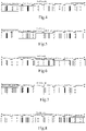
- Fig. 4 is a schematic diagram illustrating positions of transmission subframes of PSS, SSS, and PBCH according to a first exemplary implementation of the present disclosure.
- the PSS represents the PSS
- the SSS represents the PBCH.
- the PSS, SSS, and PBCH representations are the same in all of the following figures, and are not repeated in every example.
- a transmission subframe pattern provided by the present disclosure may be: PSS is transmitted on the subframe #0 of each radio frame, SSS is transmitted on the subframe #5 of even radio frames, and PBCH is transmitted on the subframe #5 of odd radio frames. Under suction condition, the PSS is transmitted 8 times and the SSS and PBCH are transmitted 4 times within 80 milliseconds.
- the period of the PSS is 10 milliseconds, and the transmission periods of the SSS and the PBCH are 20 milliseconds.
- the periods of PSS, SSS and PBCH may be different.
- the period of PSS is smaller than that of SSS or PBCH.
- Fig. 5 is a schematic diagram illustrating positions of transmission subframes of PSS, SSS, and PBCH according to a second exemplary implementation of the present disclosure.
- PSS is transmitted on subframe #0 of even radio frames
- SSS is transmitted on subframe #5 of even radio frames
- PBCH is transmitted on subframe #0 of odd radio frames.
- the PSS, SSS, and PBCH are transmitted four times within 80 milliseconds. That is, the transmission periods of the PSS, SSS, and PBCH are all 20 milliseconds.
- a schematic diagram illustrating positions of the transmission subframes shown in Fig. 6 may be used.
- Fig. 6 is a schematic diagram illustrating positions of transmission subframes of PSS, SSS, and PBCH according to a third exemplary implementation of the present disclosure.
- the PSS is transmitted on the subframe #0 of the even radio frames
- the SSS is transmitted on the subframe #5 of the even radio frame
- the PBCH is transmitted on subframe #0 and subframe #5 of the odd radio frames. That is, the transmission periods of the PSS, SSS and PBCH are all 20 milliseconds.
- the difference from the previous embodiments is that the PBCH is transmitted twice within one period.
- the two subframes are subframes #0 and #5 (both are normal subframes), and PSS and SSS occupy two subframes, respectively.
- Fig. 7 is a schematic diagram illustrating positions of transmission subframes of PSS, SSS, and PBCH according to a fourth exemplary implementation of the present disclosure.
- the PBCH is transmitted on the subframe #0 of odd radio frames.
- the "mod" represents a modulo operation.
- the transmission periods of the PSS and SSS are 40 milliseconds
- the transmission period of the PBCH is 20 milliseconds.
- a schematic diagram showing positions in transmission subframes as shown in Fig. 8 may be used.
- Fig. 8 is a schematic diagram illustrating positions of transmission subframes of PSS, SSS, and PBCH according to a fifth exemplary implementation of the present disclosure.
- Fig. 8 is a schematic diagram illustrating positions of transmission subframes of PSS, SSS, and PBCH according to a fifth exemplary implementation of the present disclosure.
- the PBCH is transmitted on the subframes #0 and #5 of odd radio frames.
- the transmission periods of the PSS and SSS are 40 milliseconds, and the transmission period of the PBCH is 20 milliseconds.
- the PBCH is transmitted twice within each period.
- the two subframes are subframes #0 and #5 (both are normal subframes)
- the PSS occupies two subframes
- the SSS occupies one subframe.
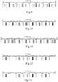
- Fig. 9 is a schematic diagram illustrating positions of transmission subframes of PSS, SSS, and PBCH according to a sixth exemplary implementation of the present disclosure.
- PSS-1 and PSS-2 are transmitted on subframes #0 and #5 of even radio frames
- the SSS is transmitted on the subframe #0 of odd radio frames
- the PBCH is transmitted on the subframe #5 of odd radio frames.
- the transmission periods of the PSS, SSS, and PBCH are 20 milliseconds, and the transmission periods of the PSS, SSS, and PBCH are the same.
- the subframes for transmitting the PSS, SSS, and PBCH are complete downlink subframes.
- the design of the PSS, SSS, and PBCH does not need to consider the configuration of the special subframe(s), and the design complexity is low.
- the transmission subframe patterns in the above-described exemplary embodiments 1 to 3 are also applicable in the FDD system. Repeated descriptions are omitted here.
- the period configurations of the PSS, SSS, and PBCH in the exemplary embodiments 1 to 3 are merely examples, and other period configurations are also possible.
- the transmission density of the PSS/SSS/PBCH may be reduced on the basis of the transmission subframe pattern illustrated above, and the transmission density reductions may be different for each signal or channel.
- the transmission density of the PSS is higher than that of the SSS and the PBCH, that is, the transmission period of the PSS is smaller than that of the SSS and the PBCH.
- the preset transmission subframe pattern satisfies the following positional relationship:
- Fig. 10 is a schematic diagram illustrating positions of transmission subframes of PSS, SSS, and PBCH according to a seventh exemplary implementation of the present disclosure.
- FIG. 11 is a schematic diagram illustrating positions of transmission subframes of PSS, SSS, and PBCH according to an eighth exemplary implementation of the present disclosure.
- Figs. 10 and 11 are schematic diagrams illustrating the positions in two transmission subframes for the PSS, SSS, and PBCH satisfying the above positional relationship.
- PSS, SSS and PBCH are transmitted on subframes #0, #5 and #6 of each of the radio frames in turn
- PSS, PBCH and SSS arc transmitted on subframes #0, #5 and #6 of each of the radio frames in turn.
- the transmission periods of the PSS, SSS and PBCH are all 10 milliseconds.
- Fig. 12 is a schematic diagram illustrating positions of transmission subframes of PSS, SSS, and PBCH according to a ninth exemplary implementation of the present disclosure.
- Fig. 13 is a schematic diagram illustrating positions of transmission subframes of PSS, SSS, and PBCH according to a tenth exemplary implementation of the present disclosure.
- the transmission period of the PSS is 10 milliseconds, while the transmission periods of the SSS and the PBCH arc increased to 20 milliseconds.
- the transmission periods of the PSS, the SSS, and the PBCH are all increased to 20 milliseconds.
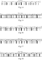
- Fig. 14 is a schematic diagram illustrating positions of transmission subframes of PSS, SSS, and PBCH according to an eleventh exemplary implementation of the present disclosure.
- FIG. 15 is a schematic diagram illustrating positions of transmission subframes of PSS, SSS, and PBCH according to a twelfth exemplary implementation of the present disclosure.
- Figs. 14 and 15 are two schematic diagrams showing positions of the PSS, SSS and PBCH in transmission subframes satisfying the above positional relationships.
- the SSS, PBCH, and PSS are transmitted on subframes #0, #1, and #5 of each radio frame in turn
- PBCH, SSS, and PSS are transmitted on subframes #0, #1, and #5 of each radio frame in turn.
- the transmission periods of the PSS, SSS and PBCH are all 10 milliseconds.
- the transmission density of PSS, SSS, and PBCH may be reduced in the same manner as in the exemplary embodiment 4-1, and repeated descriptions are omitted here.
- Fig. 16 is a schematic diagram illustrating positions of transmission subframes of PSS, SSS, and PBCH according to a thirteenth exemplary implementation of the present disclosure.
- FIG. 17 is a schematic diagram illustrating positions of transmission subframes of PSS, SSS, and PBCH according to a fourteenth exemplary implementation of the present disclosure.
- Figs. 16 and 17 are two schematic diagrams showing positions of the PSS, SSS and PBCH in transmission subframes satisfying the above positional relationships.
- SSS, PBCH, and PSS are transmitted on subframes #0, #1, and #6 of each radio frame in turn
- PBCH, SSS, and PSS are transmitted on subframes #0, #1, and #6 of each radio frame in turn.
- the transmission periods of the PSS, SSS and PBCH are all 10 milliseconds.
- the transmission density of PSS, SSS, and PBCH may be reduced in the same manner as in the exemplary embodiment 4-1, and repeated descriptions are omitted here.
- Fig. 18 is a schematic diagram illustrating positions of transmission subframes of PSS, SSS, and PBCH according to a fifteenth exemplary implementation of the present disclosure.
- FIG. 19 is a schematic diagram illustrating positions of transmission subframes of PSS, SSS, and PBCH according to a sixteenth exemplary implementation of the present disclosure.
- Figs. 18 and 19 are two schematic diagrams showing positions of the PSS, SSS and PBCH in transmission subframes satisfying the above positional relationships.
- PSS, SSS, and PBCH arc sequentially transmitted on subframes #1, #5, and #6 of each radio frame
- PSS, PBCH and SSS are sequentially transmitted on subframes #1, #5, and #6 of each radio frame.
- the transmission periods of the PSS, SSS and PBCH are all 10 milliseconds.
- the transmission density of PSS, SSS, and PBCH may be reduced in the same manner as in the exemplary embodiment 4-1, and repeated descriptions are omitted here.
- the downlink transmission area of the special subframe is related to the configuration of the special subframe.
- rate matching is performed according to a predefined downlink area.
- the predefined downlink area is preferably the largest area except the downlink control area in the downlink area in a special subframe configuration. That is, in the case of a normal cyclic prefix, 10 OFDM symbols are occupied. In the case of an extended cyclic prefix, 8 OFDM symbols are occupied.
- the downlink control area occupies the first two OFDM symbols of a subframe in a special subframe.
- the downlink transmission area of the special subframe is related to the configuration of the special subframe.
- the number of OFDM symbols occupied by the synchronization signal(s) is determined on the basis that the downlink area in the special subframe is the maximum.
- the maximum area in the downlink area occupies 12 OFDM symbols in the case of normal cyclic prefix, and 10 OFDM symbols in the case of extended cyclic prefix.
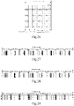
- Fig. 20 is a schematic diagram illustrating a first transmission situation for sending the PSS in a special subframe according to an exemplary implementation of the present disclosure.
- the PSS occupies 11 OFDM symbols, and the PSS starts from symbol #1 of a special subframe (the symbols in a subframe are numbered from #0).
- FIG. 21 is a schematic diagram illustrating a second transmission situation for sending the PSS in a special subframe according to an exemplary implementation of the present disclosure.
- the PSS occupies 9 OFDM symbols, and the PSS starts from the symbol #2 of the special subframe (the symbols in a subframe are numbered from #0).
- Fig. 22 may be referred to.
- Fig. 22 is a schematic diagram illustrating a third transmission situation for sending the PSS in a special subframe according to an exemplary implementation of the present disclosure.
- the PSS occupies 9 OFDM symbols, and the PSS starts from the symbol #1 of the special subframe (the symbols in a subframe are numbered from #0).
- the PSS is mapped to N consecutive OFDM symbols of a subframe. When a reference signal is encountered, a resource unit corresponding to the reference signal will be dropped.
- the preferred value or exemplary value of N is 9 or 11.
- Figs. 20-22 may be referred to, and only the symbols for transmitting the PSS in the drawings need to be replaced by the symbols for transmitting the SSS. Under such condition, for the transmitted SSS, if the reference signal is encountered, the resource unit corresponding to the reference signal will be dropped. Alternatively, the manner for sending the SSS as shown in Fig. 23 may be used.
- Fig. 23 is a schematic diagram illustrating a first transmission situation for sending the SSS in a special subframe according to an exemplary implementation of the present disclosure. The SSS is transmitted on symbols where there is no reference signal.
- Fig. 24 is a schematic diagram illustrating a second transmission situation for sending the PSS in a normal subframe according to an exemplary implementation of the present disclosure.
- Fig. 25 is a schematic diagram illustrating a third transmission situation for sending the PSS in a normal subframe according to an exemplary implementation of the present disclosure.
- Figs. 24 and 25 may be referred to, only the symbols for sending the PSS in the drawings need to be replaced by the symbols for sending the SSS.
- the manner for sending the SSS as shown in Fig. 26 may be used.
- Fig. 26 is a schcmatic diagram illustrating a first transmission situation for sending the SSS in a normal subframe according to an exemplary implementation of the present disclosure.
- the SSS is transmitted only on OFDM symbols where there is no reference signal.
- subframe #0 and subframe #5 are normal subframes
- subframe #1 and subframe #6 are special subframes.
- PSS and SSS are designed based on sequence, that is, the signals on the PSS and SSS are sequence signals
- the PBCH carries the necessary system information (MIB: master information block)
- the subframes for sending the PSS and the SSS are preferably of the same subframe type.
- both the subframes for sending the PSS and the SSS arc the normal subframes, or both the subframes for sending the PSS and the SSS are the special subframes
- the PBCH is sent on another type of subframe.
- the 8 subframe transmission patterns in the exemplary embodiment 4 the above requirements are satisfied in Fig.
- PSS and SSS are transmitted on the subframe # 0 or subframe #5, while PBCH is transmitted on subframe #1 or subframe #6.
- PSS and SSS are transmitted on subframe #1 or subframe #6, while the PBCH is transmitted on subframe #0 or subframe #5.
- the synchronization signal is mainly detected in a sequence-dependent manner (a sequence-related manner).
- the synchronization signal(s) is(are) transmitted on the special subframes #1 and #6, and accordingly the robustness of the system is better. Therefore, in the subframe transmission patterns in the exemplary embodiment 4, the subframe transmission patterns of Figs. 17 and 19 are preferred patterns.
- the preset transmission subframe pattern satisfies the following positional relationships:
- Fig. 27 is a schematic diagram illustrating positions of transmission subframes of PSS, SSS, and PBCH according to a seventeenth exemplary implementation of the present disclosure.
- FIG. 28 is a schematic diagram illustrating positions of transmission subframes of PSS, SSS, and PBCH according to an eighteenth exemplary implementation of the present disclosure.
- Figs. 27 and 28 are two schematic diagrams showing positions of the PSS, SSS and PBCH in transmission subframes satisfying the above positional relationships.
- PSS, SSS, and PBCH are sequentially transmitted on subframes #0, #4, and #5 of each radio frame
- Fig. 28 PSS, PBCH and SSS are sequentially transmitted on subframes #0, #4, and #5 of each radio frame.
- the transmission periods of the PSS, SSS and PBCH are all 10 milliseconds.
- the transmission density of PSS, SSS, and PBCH may be reduced in the same manner as in the exemplary embodiment 4-1, and repeated descriptions are omitted here.
- the number of subframes available for carrying the synchronization signal and the PBCH in the system is three, and in the present exemplary embodiment, the three subframes are assumed to be subframes #0, #4, and #9, respectively.
- the following relationships may be met: the PSS and the SSS are located in non-adjacent subframes, and the SSS and the PBCH are located in adjacent subframes.
- Fig. 29 is a schematic diagram illustrating positions of transmission subframes of PSS, SSS, and PBCH according to a nineteenth exemplary implementation of the present disclosure.
- Fig. 30 is a schematic diagram illustrating positions of transmission subframes of PSS, SSS, and PBCH according to a twentieth exemplary implementation of the present disclosure.
- Figs. 29 and 30 are two schematic diagrams showing positions of the PSS, SSS and PBCH in transmission subframes satisfying the above positional relationships.
- SSS, PSS and PBCH arc sequentially transmitted on subframes #0, #4, and #9 of each radio frame
- PBCH, PSS, and SSS are sequentially transmitted on subframes #0, #4, and #9 of each radio frame.
- the transmission periods of the PSS, SSS and PBCH are all 10 milliseconds.
- the transmission density of PSS, SSS, and PBCH may be reduced in the same manner as in the exemplary embodiment 4-1, and repeated descriptions are omitted here.
- Fig. 31 is a schematic diagram illustrating positions of transmission subframes of PSS, SSS, and PBCH according to a twenty-first exemplary implementation of the present disclosure.
- FIG. 32 is a schematic diagram illustrating positions of transmission subframes of PSS, SSS, and PBCH according to a twenty-second exemplary implementation of the present disclosure.
- Figs. 31 and 32 are two schematic diagrams showing positions of the PSS, SSS and PBCH in transmission subframes satisfying the above positional relationships.
- SSS, PSS and PBCH are sequentially transmitted on subframes #0, #5, and #9 of each radio frame
- PBCH, PSS, and SSS are sequentially transmitted on subframes #0, #5, and #9 of each radio frame.
- the transmission periods of the PSS, SSS and PBCH are all 10 milliseconds.
- the transmission periods of the PSS, SSS or PBCH may be increased.
- the transmission periods of the PBCH and the PSS are 10 milliseconds
- the PBCH and the PSS are located in the subframe #0 and subframe #5 of each radio frame, respectively
- the transmission period of the SSS is 20 milliseconds
- the SSS is located in the subframe #9 of even radio frames.
- Fig. 33 is a schematic diagram illustrating positions of transmission subframes of PSS, SSS, and PBCH according to a twenty-third exemplary implementation of the present disclosure.
- FIG. 34 is a schematic diagram illustrating positions of transmission subframes of PSS, SSS, and PBCH according to a twenty-fourth exemplary implementation of the present disclosure.
- Figs. 33 and 34 arc two schematic diagrams showing positions of the PSS, SSS and PBCH in transmission subframes satisfying the above positional relationships.
- SSS, PSS and PBCH are sequentially transmitted on subframes #4, #5, and #9 of each radio frame
- PBCH, PSS, and SSS are sequentially transmitted on subframes #4, #5, and #9 of each radio frame.
- the transmission periods of the PSS, SSS and PBCH are all 10 milliseconds.
- the transmission density of PSS, SSS, and PBCH may be reduced in the same manner as in the exemplary embodiment 4-1, and repeated descriptions are omitted here.
- the design of the PSS, SSS, and PBCH may refer to the design of the PSS, the SSS, and PBCH in the normal subframes in the TDD system, and repeated descriptions are omitted here.
- the UE distinguishes the FDD system and the TDD system by different relative positions of the PSS and the SSS.
- the terminal In a narrowband LTE system, the terminal also needs to distinguish between TDD and FDD systems. Therefore, for narrowband TDD and FDD systems, FDD and TDD systems may also be distinguished by the relative positions of PSS and SSS.
- the relative positions of the PSS and the SSS are separated by 5 subframes.
- the relative positions of the PSS and the SSS are not separated by 5 subframes.
- the relative positions of the PSS and the SSS are separated by 4 subframes. Therefore, the 4 subframe transmission patterns are the preferred subframe transmission patterns in the FDD system.
- the preset transmission subframe pattern satisfies the following positional relationships:
- Fig. 35 is a schematic diagram illustrating positions of transmission subframes of PSS, SSS, and PBCH according to a twenty-fifth exemplary implementation of the present disclosure.
- Fig. 35 is a schematic diagram showing positions of the PSS, SSS and PBCH in transmission subframes satisfying the above positional relationships.
- Fig. 35 is a schematic diagram showing positions of the PSS, SSS and PBCH in transmission subframes satisfying the above positional relationships.
- PSS-1 and PSS-2 are transmitted on subframes #0 and #5 of even radio frames
- SSS-1 and SSS-2 are transmitted on subframes #0 and #5 of odd radio frames
- the PBCH is transmitted on subframe #1 of odd radio frames.
- the transmission periods of the PSS, SSS and PBCH are all 20 milliseconds.
- the transmission density of the PBCH may be increased, and the PBCH may be transmitted on subframe #1 of each radio frame.
- the transmission density of PSS, SSS, and PBCH may be reduced in the same manner as in the exemplary embodiment 4-1, and repeated descriptions are omitted here.
- Fig. 36 is a schematic diagram illustrating positions of transmission subframes of PSS, SSS, and PBCH according to a twenty-sixth exemplary implementation of the present disclosure.
- Fig. 36 is a schematic diagram showing positions of the PSS, SSS and PBCH in transmission subframes satisfying the above positional relationships.
- Fig. 36 is a schematic diagram illustrating positions of transmission subframes of PSS, SSS, and PBCH according to a twenty-sixth exemplary implementation of the present disclosure.
- Fig. 36 is a schematic diagram showing positions of the PSS, SSS and PBCH in transmission subframes satisfying the above positional relationships.
- PSS-1 and PSS-2 are transmitted on subframes #0 and #5 of even radio frames
- SSS-1 and SSS-2 are transmitted on subframes #0 and #5 of odd radio frames
- the PBCH is transmitted on subframe #6 of odd radio frames.
- the transmission periods of the PSS, SSS and PBCH arc all 20 milliseconds.
- the transmission density of the PBCH may be increased, and the PBCH may be transmitted on subframe #1 of each radio frame.
- the transmission density of PSS, SSS, and PBCH may be reduced in the same manner as in the exemplary embodiment 4-1, and repeated descriptions are omitted here.
- Fig. 37 is a schematic diagram illustrating positions of transmission subframes of PSS, SSS, and PBCH according to a twenty-seventh exemplary implementation of the present disclosure.
- Fig. 37 is a schematic diagram showing positions of the PSS, SSS and PBCH in transmission subframes satisfying the above positional relationships.
- Fig. 37 is a schematic diagram showing positions of the PSS, SSS and PBCH in transmission subframes satisfying the above positional relationships.
- PSS-1 and PSS-2 are transmitted on subframes #1 and #6 of even radio frames
- SSS-1 and SSS-2 are transmitted on subframes #1 and #6 of odd radio frames
- the PBCH is transmitted on subframe #0 of odd radio frames.
- the transmission periods of the PSS, SSS and PBCH are all 20 milliseconds.
- the transmission density of the PBCH may be increased, and the PBCH may be transmitted on subframe #0 of each radio frame.
- the transmission density of PSS, SSS, and PBCH may be reduced in the same manner as in the exemplary embodiment 4-1, and repeated descriptions arc omitted here.
- Fig. 38 is a schematic diagram illustrating positions of transmission subframes of PSS, SSS, and PBCH according to a twenty-eighth exemplary implementation of the present disclosure.
- Fig. 38 is a schematic diagram showing positions of the PSS, SSS and PBCH in transmission subframes satisfying the above positional relationships.
- Fig. 38 is a schematic diagram showing positions of the PSS, SSS and PBCH in transmission subframes satisfying the above positional relationships.
- PSS-1 and PSS-2 are transmitted on subframes #1 and #6 of even radio frames
- SSS-1 and SSS-2 arc transmitted on subframes #1 and #6 of odd radio frames
- the PBCH is transmitted on subframe #5 of odd radio frames.
- the transmission periods of the PSS, SSS and PBCH are all 20 milliseconds.
- the transmission density of the PBCH may be increased, and the PBCH may be transmitted on subframe #5 of each radio frame.
- the transmission density of PSS, SSS, and PBCH may be reduced in the same manner as in the exemplary embodiment 4-1, and repeated descriptions are omitted here.
- the PSS and the SSS are preferably transmitted on subframes of the same subframe type, that is, the PSS and the SSS are transmitted the subframe #0 and subframe #5 at the same time, or transmitted on subframe #1 and subframe #6 at the same time.
- the closest interval between PSS and SSS is 5 ms.
- the preset transmission subframe pattern satisfies the following positional relationships:
- Fig. 39 is a schematic diagram illustrating positions of transmission subframes of PSS, SSS, and PBCH according to a twenty-ninth exemplary implementation of the present disclosure.
- Fig. 40 is a schematic diagram illustrating positions of transmission subframes of PSS, SSS, and PBCH according to a thirtieth exemplary implementation of the present disclosure.
- Figs. 39 and 40 arc two schematic diagrams showing positions of the PSS, SSS and PBCH in transmission subframes satisfying the above positional relationships.
- Fig. 39 is a schematic diagram illustrating positions of transmission subframes of PSS, SSS, and PBCH according to a twenty-ninth exemplary implementation of the present disclosure.
- Fig. 40 is a schematic diagram illustrating positions of transmission subframes of PSS, SSS, and PBCH according to a thirtieth exemplary implementation of the present disclosure.
- Figs. 39 and 40 arc two schematic diagrams showing positions of the PSS, SSS and PBCH in transmission
- PSS-1 and PSS-2 are transmitted on subframes #0 and #5 of even radio frames
- SSS-1 and SSS-2 are transmitted on subframes #0 and #5 of odd radio frames
- the PBCH is transmitted on subframe #4 of odd radio frames.
- PSS-1 and PSS-2 are transmitted on subframes #0 and #4 of even radio frames
- SSS-1 and SSS-2 are transmitted on subframes #0 and #4 of odd radio frames
- the PBCH is transmitted on subframe #5 of odd radio frames.
- the transmission periods of the PSS, SSS and PBCH are all 20 milliseconds.
- the transmission density of the PBCH may be increased, and the PBCH may be transmitted on subframe #4 or subframe #5 of each radio frame (corresponding to the subframe transmission patterns of Figs. 39 and 40 , respectively). If the overhead is to be reduced, the transmission density of PSS, SSS, and PBCH may be reduced in the same manner as in the exemplary embodiment 4-1, and repeated descriptions are omitted here.
- Fig. 41 is a schematic diagram illustrating positions of transmission subframes of PSS, SSS, and PBCH according to a thirty-first exemplary implementation of the present disclosure.
- Fig. 42 is a schematic diagram illustrating positions of transmission subframes of PSS, SSS, and PBCH according to a thirty-sccond exemplary implementation of the present disclosure.
- Figs. 41 and 42 are two schematic diagrams showing positions of the PSS, SSS and PBCH in transmission subframes satisfying the above positional relationships.
- Fig. 41 is a schematic diagram illustrating positions of transmission subframes of PSS, SSS, and PBCH according to a thirty-first exemplary implementation of the present disclosure.
- Figs. 41 and 42 are two schematic diagrams showing positions of the PSS, SSS and PBCH in transmission subframes satisfying the above positional relationships.
- Fig. 41 is a schematic diagram illustrating positions of transmission subframes of PSS, SSS, and PBCH according to a thirty-first exemplary implementation
- PSS-1 and PSS-2 are transmitted on subframes #0 and #5 of even radio frames
- SSS-1 and SSS-2 are transmitted on subframes #0 and #5 of odd radio frames
- the PBCH is transmitted on subframe #9 of even radio frames.
- PSS-1 and PSS-2 are transmitted on subframes #5 and #9 of even radio frames
- SSS-1 and SSS-2 are transmitted on subframes #5 and #9 of odd radio frames
- the PBCH is transmitted on subframe #0 of even radio frames.
- the transmission periods of the PSS, SSS and PBCH arc all 20 milliseconds.
- the transmission density of the PBCH may be increased, and the PBCH may be transmitted on subframe #9 or subframe #0 of each radio frame (corresponding to the subframe transmission patterns of Figs. 41 and 42 , respectively). If the overhead is to be reduced, the transmission density of PSS, SSS, and PBCH may be reduced in the same manner as in the exemplary embodiment 4-1, and repeated descriptions are omitted here.
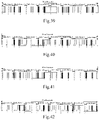
- Fig. 43 is a schematic diagram illustrating positions of transmission subframes of PSS, SSS, and PBCH according to a thirty-third exemplary implementation of the present disclosure.
- Fig. 44 is a schematic diagram illustrating positions of transmission subframes of PSS, SSS, and PBCH according to a thirty-fourth exemplary implementation of the present disclosure.
- Figs. 43 and 44 are schematic diagrams showing positions of the PSS, SSS and PBCH in transmission subframes satisfying the above positional relationships.
- Fig. 43 is a schematic diagram illustrating positions of transmission subframes of PSS, SSS, and PBCH according to a thirty-third exemplary implementation of the present disclosure.
- PSS-1 and PSS-2 are transmitted on subframes #4 and #9 of even radio frames
- SSS-1 and SSS-2 are transmitted on subframes #4 and #9 of odd radio frames
- the PBCH is transmitted on subframe #0 of even radio frames.
- PSS-1 and PSS-2 are transmitted on subframes #0 and #4 of even radio frames
- SSS-1 and SSS-2 are transmitted on subframes #0 and #4 of odd radio frames
- the PBCH is transmitted on subframe #9 of even radio frames.
- the transmission periods of the PSS, SSS and PBCH are all 20 milliseconds.
- the transmission density of the PBCH may be increased, and the PBCH may be transmitted on subframe #0 or subframe #9 of each radio frame (corresponding to the subframe transmission patterns of Figs. 43 and 44 , respectively). If the overhead is to be reduced, the transmission density of PSS, SSS, and PBCH may be reduced in the same manner as in the exemplary embodiment 4-1, and repeated descriptions are omitted here.
- Fig. 45 is a schematic diagram illustrating positions of transmission subframes of PSS, SSS, and PBCH according to a thirty-fifth exemplary implementation of the present disclosure.
- Fig. 46 is a schematic diagram illustrating positions of transmission subframes of PSS, SSS, and PBCH according to a thirty-sixth exemplary implementation of the present disclosure.
- Figs. 45 and 46 are two schematic diagrams showing positions of the PSS, SSS and PBCH in transmission subframes satisfying the above positional relationships. In Fig.
- PSS-1 and PSS-2 are transmitted on subframes #4 and #9 of even radio frames
- SSS-1 and SSS-2 are transmitted on subframes #4 and #9 of odd radio frames
- the PBCH is transmitted on subframe #5 of odd radio frames.
- PSS-1 and PSS-2 are transmitted on subframes #5 and #9 of even radio frames
- SSS-1 and SSS-2 are transmitted on subframes #5 and #9 of odd radio frames
- the PBCH is transmitted on subframe #4 of odd radio frames.
- the transmission periods of the PSS, SSS and PBCH are all 20 milliseconds.
- the transmission density of the PBCH may be increased, and the PBCH may be transmitted on subframe #5 or subframe #4 of each radio frame (corresponding to the subframe transmission patterns of Figs. 45 and 46 , respectively). If the overhead is to be reduced, the transmission density of PSS, SSS, and PBCH may be reduced in the same manner as in the exemplary embodiment 4-1, and repeated descriptions are omitted here.
- the relative positions of the PSS and the SSS are separated by 5 subframes.
- the relative positions of the PSS and the SSS are not separated by 5 subframes.
- the relative positions of the PSS and the SSS are separated by 6 subframes. Therefore, the 4 subframe transmission patterns are the preferred subframe transmission patterns in the FDD system.
- the preset transmission sub frame pattern satisfies the following positional relationship:
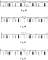
- Fig. 47 is a schematic diagram illustrating positions of transmission subframes of PSS, SSS, and PBCH according to a thirty-seventh exemplary implementation of the present disclosure.
- Fig. 47 is a schematic diagram showing positions of the PSS, SSS and PBCH in transmission subframes satisfying the above positional relationships. In Fig.
- PSS-1 and PSS-2 are transmitted on subframes #4 and #5 of even radio frames
- SSS-1 and SSS-2 are transmitted on subframes #4 and #5 of odd radio frames
- the PBCH is transmitted on subframe #0 of even radio frames.
- the transmission periods of the PSS, SSS and PBCH are all 20 milliseconds.
- the PBCH may be transmitted on subframe #0 of odd radio frames.
- the transmission density of the PBCH may be increased, and the PBCH may be transmitted on subframe #0 of each radio frame.
- the transmission density of PSS, SSS, and PBCH may be reduced in the same manner as in the exemplary embodiment 4-1, and repeated descriptions are omitted here.
- Fig. 48 is a schematic diagram illustrating positions of transmission subframes of PSS, SSS, and PBCH according to a thirty-eighth exemplary implementation of the present disclosure.
- Fig. 48 is a schematic diagram showing positions of the PSS, SSS and PBCH in transmission subframes satisfying the above positional relationships.
- Fig. 48 is a schematic diagram showing positions of the PSS, SSS and PBCH in transmission subframes satisfying the above positional relationships.
- PSS-1 and PSS-2 are transmitted on subframe #0 of even radio frames and subframe #9 of odd radio frames
- SSS-1 and SSS-2 are transmitted on subframe #0 of odd radio frames and subframe #9 of even radio frames
- the PBCH is transmitted on subframe #5 of even radio frames.
- the transmission periods of the PSS, SSS and PBCH are all 20 milliseconds.
- the PBCH may be transmitted on subframe #5 of odd radio frames.
- the transmission density of the PBCH may be increased, and the PBCH may be transmitted on subframe #5 of each radio frame.
- the transmission density of PSS, SSS, and PBCH may be reduced in the same manner as in the exemplary embodiment 4-1, and repeated descriptions are omitted here.
- Fig. 49 is a schematic diagram illustrating positions of transmission subframes of PSS, SSS, and PBCH according to a thirty-ninth exemplary implementation of the present disclosure.
- Fig. 49 is a schematic diagram showing positions of the PSS, SSS and PBCH in transmission subframes satisfying the above positional relationships.
- Fig. 49 is a schematic diagram showing positions of the PSS, SSS and PBCH in transmission subframes satisfying the above positional relationships.
- PSS-1 and PSS-2 are transmitted on subframe #0 of even radio frames and subframe #9 of odd radio frames
- SSS-1 and SSS-2 arc transmitted on subframe #0 of odd radio frames and subframe #9 of even radio frames
- the PBCH is transmitted on subframe #4 of even radio frames.
- the transmission periods of the PSS, SSS and PBCH are all 20 milliseconds.
- the PBCH may be transmitted on subframe #4 of odd radio frames.
- the transmission density of the PBCH may be increased, and the PBCH may be transmitted on subframe #4 of each radio frame.
- the transmission density of PSS, SSS, and PBCH may be reduced in the same manner as in the exemplary embodiment 4-1, and repeated descriptions arc omitted here.
- Fig. 50 is a schematic diagram illustrating positions of transmission subframes of PSS, SSS, and PBCH according to a fortieth exemplary implementation of the present disclosure.
- Fig. 50 is a schematic diagram showing positions of the PSS, SSS and PBCH in transmission subframes satisfying the above positional relationships.
- Fig. 50 is a schematic diagram showing positions of the PSS, SSS and PBCH in transmission subframes satisfying the above positional relationships.
- PSS-1 and PSS-2 are transmitted on subframe #4 and subframe #5 of even radio frames
- SSS-1 and SSS-2 are transmitted on subframe #4 and subframe #5 of odd radio frames
- the PBCH is transmitted on subframe #9 of even radio frames.
- the transmission periods of the PSS, SSS and PBCH are all 20 milliseconds.
- the PBCH may be transmitted on subframe #9 of odd radio frames.
- the transmission density of the PBCH may be increased, and the PBCH may be transmitted on subframe #9 of each radio frame.
- the transmission density of PSS, SSS, and PBCH may be reduced in the same manner as in the exemplary embodiment 4-1, and repeated descriptions are omitted here.
- the relative positions of the PSS and the SSS are separated by 5 subframes, and two PSSs or two SSSs arc separated by 5 subframes.
- PSS and SSS are adjacent to each other, both the interval between the PSS and the SSS, and the interval between two PSSs or two SSSs are different from that of the TDD system.
- the subframe transmission patterns in the exemplary embodiment may be used to distinguish from that of the TDD system.
- the preset transmission pattern satisfies the following positional relationship:
- Fig. 51 is a schematic diagram illustrating positions of transmission subframes of PSS, SSS, and PBCH according to a forty-first exemplary implementation of the present disclosure.
- Fig. 51 is a schematic diagram showing positions of the PSS, SSS and PBCH in transmission subframes satisfying the above positional relationships.
- PSS-1 and PSS-2 are transmitted on subframe #0 and subframe #5 of even radio frames
- SSS and PBCH are transmitted on subframe #0 and subframe #1 of odd radio frames, respectively.
- the transmission periods of the PSS, SSS and PBCH are all 20 milliseconds.
- the transmission density of the PBCH may be increased, and the PBCH may be transmitted on subframe #1 of each radio frame.
- the transmission density of PSS, SSS, and PBCH may be reduced in the same manner as in the exemplary embodiment 4-1, and repeated descriptions are omitted here.
- Fig. 52 is a schcmatic diagram illustrating positions of transmission subframes of PSS, SSS, and PBCH according to a forty-second exemplary implementation of the present disclosure.
- Fig. 52 is a schematic diagram showing positions of the PSS, SSS and PBCH in transmission subframes satisfying the above positional relationships.
- PSS-1 and PSS-2 are transmitted on subframe #0 and subframe #5 of even radio frames
- SSS and PBCH are transmitted on subframe #5 and subframe #6 of odd radio frames, respectively.
- the transmission periods of the PSS, SSS and PBCH are all 20 milliseconds.
- the transmission density of the PBCH may be increased, and the PBCH may be transmitted on subframe #6 of each radio frame.
- the transmission density of PSS, SSS, and PBCH may be reduced in the same manner as in the exemplary embodiment 4-1, and repeated descriptions are omitted here.
- Fig. 53 is a schematic diagram illustrating positions of transmission subframes of PSS, SSS, and PBCH according to a forty-third exemplary implementation of the present disclosure.
- Fig. 53 is a schematic diagram showing positions of the PSS, SSS and PBCH in transmission subframes satisfying the above positional relationships.
- PSS-1 and PSS-2 are transmitted on subframe #1 and subframe #6 of even radio frames
- PBCH and SSS are transmitted on subframe #0 and subframe #1 of odd radio frames, respectively.
- the transmission periods of the PSS, SSS and PBCH are all 20 milliseconds.
- the transmission density of the PBCH may be increased, and the PBCH may be transmitted on subframe #0 of each radio frame.
- the transmission density of PSS, SSS, and PBCH may be reduced in the same manner as in the exemplary embodiment 4-1, and repeated descriptions are omitted here.
- Fig. 54 is a schematic diagram illustrating positions of transmission subframes of PSS, SSS, and PBCH according to a forty-fourth exemplary implementation of the present disclosure.
- Fig. 54 is a schematic diagram showing positions of the PSS, SSS and PBCH in transmission subframes satisfying the above positional relationships.
- PSS-1 and PSS-2 are transmitted on subframe #1 and subframe #6 of even radio frames
- PBCH and SSS are transmitted on subframe #5 and subframe #6 of odd radio frames, respectively.
- the transmission periods of the PSS, SSS and PBCH arc all 20 milliseconds.
- the transmission density of the PBCH may be increased, and the PBCH may be transmitted on subframe #5 of each radio frame.
- the transmission density of PSS, SSS, and PBCH may be reduced in the same manner as in the exemplary embodiment 4-1, and repeated descriptions are omitted here.
- the preset transmission pattern satisfies the following positional relationship:
- Fig. 55 is a schematic diagram illustrating positions of transmission subframes of PSS, SSS, and PBCH according to a forty-fifth exemplary implementation of the present disclosure.
- Fig. 56 is a schematic diagram illustrating positions of transmission subframes of PSS, SSS, and PBCH according to a forty-sixth exemplary implementation of the present disclosure.
- Figs. 55 and 56 are two schematic diagrams showing positions of the PSS, SSS and PBCH in transmission subframes satisfying the above positional relationships. In Fig.
- PSS-1 and PSS-2 arc transmitted on subframe #0 and subframe #5 of even radio frames, and PBCH and SSS are transmitted on subframe #4 and subframe #5 of odd radio frames, respectively.
- PSS-1 and PSS-2 are transmitted on subframe #0 and subframe #4 of even radio frames, and SSS and PBCH are transmitted on subframe #4 and subframe #5 of odd radio frames, respectively.
- the transmission periods of the PSS, SSS and PBCH are all 20 milliseconds.
- the transmission density of the PBCH may be increased, and the PBCH may be transmitted on subframe #4 or subframe #5 of each radio frame (corresponding to the subframe transmission patterns of Figs. 55 and 56 , respectively). If the overhead is to be reduced, the transmission density of PSS, SSS, and PBCH may be reduced in the same manner as in the exemplary embodiment 4-1, and repeated descriptions are omitted here.
- Fig. 57 is a schematic diagram illustrating positions of transmission subframes of PSS, SSS, and PBCH according to a forty-seventh exemplary implementation of the present disclosure.
- Fig. 58 is a schematic diagram illustrating positions of transmission subframes of PSS, SSS, and PBCH according to a forty-eighth exemplary implementation of the present disclosure.
- Figs. 57 and 58 are two schematic diagrams showing positions of the PSS, SSS and PBCH in transmission subframes satisfying the above positional relationships. In Fig.
- PSS-1 and PSS-2 are transmitted on subframe #0 and subframe #5 of even radio frames, and PBCH and SSS are transmitted on subframe #9 of even radio frames and subframe #0 of odd radio frames, respectively.
- PSS-1 and PSS-2 are transmitted on subframe #5 and subframe #9 of even radio frames, and SSS and PBCH are transmitted on subframe #9 of odd radio frames and subframe #0 of even radio frames, respectively.
- the transmission periods of the PSS, SSS and PBCH are all 20 milliseconds.
- the transmission density of the PBCH may be increased, and the PBCH may be transmitted on subframe #9 or subframe #0 of each radio frame (corresponding to the subframe transmission patterns of Figs. 57 and 58 , rcspcctivcly). If the overhead is to be reduced, the transmission density of PSS, SSS, and PBCH may be reduced in the same manner as in the exemplary embodiment 4-1, and repeated descriptions are omitted here.
- Fig. 59 is a schematic diagram illustrating positions of transmission subframes of PSS, SSS, and PBCH according to a forty-ninth exemplary implementation of the present disclosure.
- Fig. 60 is a schcmatic diagram illustrating positions of transmission subframes of PSS, SSS, and PBCH according to a fiftieth exemplary implementation of the present disclosure.
- Figs. 59 and 60 are two schematic diagrams showing positions of the PSS, SSS and PBCH in transmission subframes satisfying the above positional relationships.
- Fig. 59 is a schematic diagram illustrating positions of transmission subframes of PSS, SSS, and PBCH according to a forty-ninth exemplary implementation of the present disclosure.
- Fig. 60 is a schcmatic diagram illustrating positions of transmission subframes of PSS, SSS, and PBCH according to a fiftieth exemplary implementation of the present disclosure.
- Figs. 59 and 60 are two schematic diagrams showing positions of
- PSS-1 and PSS-2 are transmitted on subframe #0 and subframe #4 of even radio frames, and PBCH and SSS are transmitted on subframe #9 of even radio frames and subframe #0 of odd radio frames, respectively.
- PSS-1 and PSS-2 are transmitted on subframe #4 and subframe #9 of even radio frames, and SSS and PBCH are transmitted on subframe #9 of odd radio frames and subframe #0 of even radio frames, respectively.
- the transmission periods of the PSS, SSS and PBCH are all 20 milliseconds.
- the transmission density of the PBCH may be increased, and the PBCH may be transmitted on subframe #9 or subframe #0 of each radio frame (corresponding to the subframe transmission patterns of Figs. 59 and 60 , respectively). If the overhead is to be reduced, the transmission density of PSS, SSS, and PBCH may be reduced in the same manner as in the exemplary embodiment 4-1, and repeated descriptions are omitted here.
- Fig. 61 is a schematic diagram illustrating positions of transmission subframes of PSS, SSS, and PBCH according to a fifty-first exemplary implementation of the present disclosure.
- Fig. 62 is a schematic diagram illustrating positions of transmission subframes of PSS, SSS, and PBCH according to a fifty-second exemplary implementation of the present disclosure.
- Figs. 61 and 62 are two schematic diagrams showing positions of the PSS, SSS and PBCH in transmission subframes satisfying the above positional relationships. In Fig.
- PSS-1 and PSS-2 are transmitted on subframe #4 and subframe #9 of even radio frames, and SSS and PBCH are transmitted on subframe #9 and subframe #5 of odd radio frames, respectively.
- PSS-1 and PSS-2 are transmitted on subframe #5 and subframe #9 of even radio frames, and PBCH and SSS are transmitted on subframe #4 and subframe #5 of odd radio frames, respectively.
- the transmission periods of the PSS, SSS and PBCH are all 20 milliseconds.
- the transmission density of the PBCH may be increased, and the PBCH may be transmitted on subframe #5 or subframe #4 of each radio frame (corresponding to the subframe transmission patterns of Figs. 61 and 62 , respectively). If the overhead is to be reduced, the transmission density of PSS, SSS, and PBCH may be reduced in the same manner as in the exemplary embodiment 4-1, and repeated descriptions are omitted here.
- the preferred subframe transmission patterns of the TDD and FDD systems may be selected in accordance with the method mentioned in Exemplary Embodiment 7, and repeated descriptions are omitted here.
- the preset transmission pattern satisfies the following positional relationship:
- Fig. 63 is a schematic diagram illustrating positions of transmission subframes of PSS, SSS, and PBCH according to a fifty-third exemplary implementation of the present disclosure.
- Fig. 63 is a schematic diagram showing positions of the PSS, SSS and PBCH in transmission subframes satisfying the above positional relationships.
- Fig. 63 is a schematic diagram showing positions of the PSS, SSS and PBCH in transmission subframes satisfying the above positional relationships.
- PSS-1 and PSS-2 are transmitted on subframe #0 and subframe #5 of even radio frames
- SSS-1 and SSS-2 arc transmitted on subframe #9 of even radio frames and subframe #0 of odd radio frames
- PBCH is transmitted on subframe #4 of each radio frame.
- the transmission periods of the PSS and SSS are all 20 milliseconds
- the transmission period of the PBCH is 10 milliseconds.
- the PBCH is transmitted on subframe #4 of each radio frame, which is only one of the exemplary embodiments. Since the subframes in the system which may carry the synchronization signal and the PBCH are subframes #0, #4, #5 and #9, the PBCH may be sent on any one of the above-mentioned subframes which is not used to transmit the PSS and SSS. If the extreme coverage scenario is considered, the transmission density of the PBCH may be increased, and the PBCH may be transmitted on one or more subframes which are not used to transmit the PSS and the SSS.
- the transmission density of PSS, SSS, and PBCH may be reduced in the same manner as in the exemplary embodiment 4-1, and repeated descriptions are omitted here.
- Fig. 64 is a schematic diagram illustrating positions of transmission subframes of PSS, SSS, and PBCH according to a fifty-fourth exemplary implementation of the present disclosure.
- Fig. 64 is a schematic diagram showing positions of the PSS, SSS and PBCH in transmission subframes satisfying the above positional relationships.
- Fig. 64 is a schematic diagram showing positions of the PSS, SSS and PBCH in transmission subframes satisfying the above positional relationships.
- PSS-1 and PSS-2 arc transmitted on subframe #0 and subframe #4 of even radio frames
- SSS-1 and SSS-2 are respectively transmitted on subframe #9 of even radio frames and subframe #0 of odd radio frames
- PBCH is transmitted on subframe #5 of each radio frame.
- the transmission periods of the PSS, SSS are both 20 milliseconds.
- the PBCH is transmitted on subframe #5 of odd radio frame, which is only one of the exemplary embodiments. Since the subframes in the system which may carry the synchronization signal and the PBCH are subframes #0, #4, #5 and #9, the PBCH may be sent on any one of the above-mentioned subframes which is not used to transmit the PSS and SSS. If the extreme coverage scenario is considered, the transmission density of the PBCH may be increased, and the PBCH may be transmitted on one or more subframes which are not used to transmit the PSS and the SSS.
- the transmission density of PSS, SSS, and PBCH may be reduced in the same manner as in the exemplary embodiment 4-1, and repeated descriptions are omitted here.
- Fig. 65 is a schematic diagram illustrating positions of transmission subframes of PSS, SSS, and PBCH according to a fifty-fifth exemplary implementation of the present disclosure. Repeated descriptions are omitted here.
- the preset transmission subframe pattern satisfies the following positional relationship:
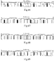
- Fig. 66 is a schematic diagram illustrating positions of transmission subframes of PSS, SSS, and PBCH according to a fifty-sixth exemplary implementation of the present disclosure.
- Fig. 66 is a schematic diagram showing positions of the PSS, SSS and PBCH in transmission subframes satisfying the above positional relationships.
- Fig. 66 is a schematic diagram showing positions of the PSS, SSS and PBCH in transmission subframes satisfying the above positional relationships.
- PSS-1 and PSS-2 arc transmitted on subframe #4 and subframe #5 of even radio frames
- SSS-1 and SSS-2 are respectively transmitted on subframe #9 of even radio frames and subframe #0 of odd radio frames
- PBCH is transmitted on subframe #0 of even radio frame.
- the transmission periods of the PSS, SSS and PBCH are all 20 milliseconds.
- the PBCH is transmitted on subframe #0 of even radio frame, which is only one of the exemplary embodiments. Since the subframes in the system which may carry the synchronization signal and the PBCH are subframes #0, #4, #5 and #9, the PBCH may be sent on any one of the above-mentioned subframes which is not used to transmit the PSS and SSS. If the extreme coverage scenario is considered, the transmission density of the PBCH may be increased, and the PBCH may be transmitted on one or more subframes which are not used to transmit the PSS and the SSS.
- the transmission density of PSS, SSS, and PBCH may be reduced in the same manner as in the exemplary embodiment 4-1, and repeated descriptions are omitted here.
- Fig. 67 is a schematic diagram illustrating positions of transmission subframes of PSS, SSS, and PBCH according to a fifty-seventh exemplary implementation of the present disclosure.
- Fig. 67 is a schematic diagram showing positions of the PSS, SSS and PBCH in transmission subframes satisfying the above positional relationships.
- Fig. 67 is a schematic diagram showing positions of the PSS, SSS and PBCH in transmission subframes satisfying the above positional relationships.
- PSS-1 and PSS-2 are transmitted on subframe #9 of odd radio frames and subframe #0 of even radio frames
- SSS-1 and SSS-2 are transmitted on subframes #4 and #4 of even radio frame respectively
- PBCH is transmitted on subframe #0 of odd radio frames.
- the transmission periods of the PSS, SSS and PBCH are all 20 milliseconds.
- the PBCH is transmitted on subframe #0 of odd radio frames, which is only one of the exemplary embodiments. Since the subframes in the system which may carry the synchronization signal and the PBCH are subframes #0, #4, #5 and #9, the PBCH may be sent on any one of the above-mentioned subframes which is not used to transmit the PSS and SSS. If the extreme coverage scenario is considered, the transmission density of the PBCH may be increased, and the PBCH may be transmitted on one or more subframes which are not used to transmit the PSS and the SSS.
- the transmission density of PSS, SSS, and PBCH may be reduced in the same manner as in the exemplary embodiment 4-1, and repeated descriptions are omitted here.
- the preset transmission subframe pattern satisfies the following positional relationship:
- Fig. 68 is a schematic diagram illustrating positions of transmission subframes of PSS, SSS, and PBCH according to a fifty-eighth exemplary implementation of the present disclosure.
- Fig. 68 is a schematic diagram showing positions of the PSS, SSS and PBCH in transmission subframes satisfying the above positional relationships.
- PSS-1 and PSS-2 are transmitted on subframe #4 and subframe #5 of each radio frame
- PBCH and SSS are transmitted on subframes #0 and #9 of even radio frame.
- the transmission periods of the PSS, SSS and PBCH are all 10 milliseconds. Further, the positions of the transmission subframes of the PBCH and SSS may be interchanged.
- the transmission density of PSS, SSS, and PBCH may be reduced in the same manner as in the exemplary embodiment 4-1, and repeated descriptions are omitted here.
- the design of the synchronization signal since the terminal does not have any system-related information when detecting the synchronization signal, the design of the synchronization signal needs to be the same in all three operation modes.
- a current working hypothesis is that the first three OFDM symbols of a subframe are not used for transmission of a synchronization signal. This mainly considers coexistence with the traditional LTE system in the in-band operation mode. The first three OFDM symbols of the downlink subframe of the LTE system are used to send downlink control information. This working hypothesis also applies to the stand-alone operation mode and the guard band operation mode. For the guard band operation mode or the stand-alone operation mode, no downlink control information of the LTE system needs to be transmitted.
- the physical broadcast channel may be transmitted using the first three OFDM symbols of the subframes that transmit the synchronization signals (including PSS and SSS).
- the synchronization signal subframe may carry ⁇ 3( N + M )/ K ⁇ PBCHs within 80 milliseconds.
- Table 1 shows the number of PBCHs that may be carried by the remaining symbols of subframes that send synchronization signals under different candidate values of M, N.
- Sending the PBCH on the remaining OFDM symbols of the subframe in which the synchronization signal is transmitted may reduce the overhead of the PBCH or increase the coverage of the PBCH.
- the base station may indicate the operation mode through the transmission position of the PBCH, which is specifically as follows.
- the PBCH is sent on the PBCH subframe in the above embodiment.
- the operation mode is the stand-alone operation mode
- the PBCH is sent in the first three OFDM symbols of the PSS subframe in the above embodiment.
- the operation mode is the guard band operation mode
- the PBCH is transmitted in the first three OFDM symbols of the SSS subframe in the above embodiment.
- the operation mode is the in-band operation mode
- the PBCH is sent on the PBCH subframe in the above embodiment.
- the operation mode is the stand-alone operation mode
- the PBCH is sent in the first three OFDM symbols of the SSS subframe in the above embodiment.
- the operation mode is the guard band operation mode
- the PBCH is transmitted in the first three OFDM symbols of the PSS subframe in the above embodiment.
- the terminal After completing the synchronization signal detection, the terminal performs PBCH blind detection based on different PBCH location hypotheses.
- the operation mode may be determined according to the location of the detected PBCH. The above method is suitable for scenarios where the transmission density of PSS and SSS is relatively high.
- the Exemplary Embodiment 14 shows that different operation modes are distinguished by the manner in which the first three OFDM symbols of the PSS and the SSS carry the PBCH. Another way may be that the operation modes of the narrowband system may be indicated by the transmission periods of the PSS/SSS/PBCH and/or the positions of the PSS/SSS/PBCH within a period.
- An exemplary embodiment may be as follows.
- three different transmission subframe patterns are selected to indicate different operation modes, respectively, and the terminal performs synchronization signal and PBCH detection on the three different transmission subframe patterns to determine the operation mode of the system.
- the duplex mode of the system is distinguished by the relative positions of the PSS and the SSS.
- the duplex mode may also be distinguished by a relative spacing (or interval) between the two PSSs.
- the subframes occupied by the two PSSs in the TDD system are separated by 5 subframes, and in the FDD system, the subframes occupied the two PSSs may be adjacent to each other, or may be separated by 4 subframes or 5 subframes. Therefore, the current duplex mode of the system which the terminal resides in may be indicated by the relative spacing of the two PSSs.
- subframes occupied by two PSSs are separated by 5 subframes; and in an FDD system, subframes occupied by two PSSs are adjacent or separated by 4 subframes.
- the relative position of the two PSSs may be used to determine the duplex mode of the current system.
- the terminal determines that the current system duplex mode is TDD.
- the terminal determines that the current system duplex mode is FDD.
- the method according to the above embodiments can be implemented by means of software plus a necessary general hardware platform.
- the hardware can also be used, but in many cases, the former is better implementation.
- the essence or the part that contributes to the prior art of technical solutions of the present disclosure can be embodied in the form of a software product.
- the computer software product is stored in a storage medium (such as ROM/RAM, magnetic disk, optical disc), including instructions for enabling a terminal device (which may be a mobile phone, a computer, a server, or a network device, etc.) to perform the methods described in the various embodiments of the present disclosure.
- the above modules may be implemented by software or hardware. For the latter, it may be implemented by, but not limited to, the following manner: the above modules are all located in the same processor; or the above modules are located in multiple processors.
- An embodiment of the present disclosure also provides a storage medium.
- the above storage medium may be configured to store program codes for executing the following steps:
- the foregoing storage medium may include but is not limited to a U disk, a Read-Only Memory (ROM), a Random Access Memory (RAM), a mobile hard disk, and a magnetic disk, an optical disc or other medium that can store program codes.
- the processor executes the program codes stored in the storage medium to perform the method steps in the above embodiments.
- each module or step of the present disclosure described above may be implemented by general-purpose computing device(s), which can be concentrated on a single computing device or distributed over a network of multiple computing devices.
- the modules or steps may be implemented with program codes that are executable by the computing device(s) so that they may be stored in the storage device to be executed by the computing device(s).
- the illustrated or described steps may performed in an order different from that described herein, or they may be separately fabricated into individual integrated circuit modules, or some of the modules or steps described herein may be implemented as a single integrated circuit module.
- the present disclosure is not limited to any specific combination of hardware and software.
- the base station periodically transmits a synchronization signal and a Physical Broadcast Channel PBCH to a terminal according to a preset transmission subframe pattern
- the synchronization signal includes a primary synchronization signal PSS and a secondary synchronization signal SSS
- the transmission subframe pattern indicates a position of a transmission subframe for transmitting the synchronization signal and the PBCH in a plurality of radio frames within a predetermined period of time.
Landscapes
- Engineering & Computer Science (AREA)
- Signal Processing (AREA)
- Computer Networks & Wireless Communication (AREA)
- Mobile Radio Communication Systems (AREA)
Claims (4)
- Procédé d'émission de signal de synchronisation, comprenant :l'émission périodique (S104), par une station de base, d'un signal de synchronisation et d'un canal physique de diffusion, PBCH, vers un terminal selon un modèle de sous-trame d'émission prédéfini, dans lequel le signal de synchronisation comprend un signal de synchronisation primaire, PSS, et un signal de synchronisation secondaire, SSS, et le modèle de sous-trame d'émission indique des positions de sous-trames d'émission du signal de synchronisation et du PBCH dans une pluralité de trames radio au sein d'une période de temps prédéterminée, dans lequeldans chacune de la pluralité de trames radio, le PSS est émis sur une première sous-trame, le SSS est émis sur une deuxième sous-trame et le PBCH est émis sur une troisième sous-trame, dans lequel la première sous-trame et la deuxième sous-trame ne sont pas adjacentes, et la deuxième sous-trame et la troisième sous-trame sont adjacentes ;pour un système duplex à répartition dans le temps, TDD, la première sous-trame, la deuxième sous-trame et la troisième sous-trame sont sélectionnées parmi : une sous-trame #0, une sous-trame #1, une sous-trame #5 et une sous-trame #6, et des indices des sous-trames sont les indices des sous-trames au sein d'une trame radio, en partant du #0 ;pour un système duplex à répartition en fréquence, FDD, la première sous-trame, la deuxième sous-trame et la troisième sous-trame sont sélectionnées parmi : une sous-trame #0, une sous-trame #4, une sous-trame #5 et une sous-trame #9, et des indices des sous-trames sont les indices des sous-trames au sein d'une trame radio, en partant du #0 ; et caractérisé en ce que,en réponse au PSS émis sur une sous-trame normale, le PSS est émis sur l'ensemble des symboles de multiplexage par répartition orthogonale de la fréquence, OFDM, de la sous-trame normale, à l'exception des symboles OFDM occupés par une zone de commande de liaison descendante ;en réponse au SSS émis sur une sous-trame normale, le SSS est émis sur l'ensemble des symboles OFDM, de la sous-trame normale, à l'exception des symboles OFDM occupés par une zone de commande de liaison descendante.
- Procédé selon la revendication 1, dans lequel le modèle de sous-trame d'émission est déterminé selon le nombre de sous-trames disponibles pour porter le signal de synchronisation et le PBCH dans une trame radio d'un système.
- Dispositif d'émission de signal de synchronisation, situé dans une station de base, comprenant :un module d'émission (24) configuré pour émettre périodiquement un signal de synchronisation et un canal physique de diffusion, PBCH, vers un terminal selon un modèle de sous-trame d'émission prédéfini, dans lequel le signal de synchronisation comprend un signal de synchronisation primaire PSS et un signal de synchronisation secondaire SSS, et le modèle de sous-trame d'émission indique des positions de sous-trames d'émission du signal de synchronisation et du PBCH dans une pluralité de trames radio au sein d'une période de temps prédéterminée,dans chacune de la pluralité de trames radio, le PSS est émis sur une première sous-trame, le SSS est émis sur une deuxième sous-trame et le PBCH est émis sur une troisième sous-trame, dans lequel la première sous-trame et la deuxième sous-trame ne sont pas adjacentes, et la deuxième sous-trame et la troisième sous-trame sont adjacentes ;pour un système duplex à répartition dans le temps, TDD, la première sous-trame, la deuxième sous-trame et la troisième sous-trame sont sélectionnées parmi : une sous-trame #0, une sous-trame #1, une sous-trame #5 et une sous-trame #6, et des indices des sous-trames sont les indices des sous-trames au sein d'une trame radio, en partant du #0 ;pour un système duplex à répartition en fréquence, FDD, la première sous-trame, la deuxième sous-trame et la troisième sous-trame sont sélectionnées parmi : une sous-trame #0, une sous-trame #4, une sous-trame #5 et une sous-trame #9, et des indices des sous-trames sont les indices des sous-trames au sein d'une trame radio, en partant du #0 ; et caractérisé en ce que,en réponse au PSS émis sur une sous-trame normale, le PSS est émis sur l'ensemble des symboles de multiplexage par répartition orthogonale de la fréquence, OFDM, de la sous-trame normale, à l'exception des symboles OFDM occupés par une zone de commande de liaison descendante ;en réponse au SSS émis sur une sous-trame normale, le SSS est émis sur l'ensemble des symboles OFDM, de la sous-trame normale, à l'exception des symboles OFDM occupés par une zone de commande de liaison descendante.
- Système d'émission de signal de synchronisation, comprenant :une station de base ; etun terminal ;dans lequel :la station de base émet périodiquement (S104) un signal de synchronisation et un canal physique de diffusion, PBCH, vers un terminal selon un modèle de sous-trame d'émission prédéfini, dans lequel le signal de synchronisation comprend un signal de synchronisation primaire PSS et un signal de synchronisation secondaire SSS, et le modèle de sous-trame d'émission indique des positions de sous-trames d'émission du signal de synchronisation et du PBCH dans une pluralité de trames radio au sein d'une période de temps prédéterminée ; etle terminal reçoit périodiquement et de manière répétée le signal de synchronisation et le PBCH, dans chacune de la pluralité de trames radio, le PSS est émis sur une première sous-trame, le SSS est émis sur une deuxième sous-trame et le PBCH est émis sur une troisième sous-trame, dans lequel la première sous-trame et la deuxième sous-trame ne sont pas adjacentes, et la deuxième sous-trame et la troisième sous-trame sont adjacentes ;pour un système duplex à répartition dans le temps, TDD, la première sous-trame, la deuxième sous-trame et la troisième sous-trame sont sélectionnées parmi : une sous-trame #0, une sous-trame #1, une sous-trame #5 et une sous-trame #6, et des indices des sous-trames sont les indices des sous-trames au sein d'une trame radio, en partant du #0 ;pour un système duplex à répartition en fréquence, FDD, la première sous-trame, la deuxième sous-trame et la troisième sous-trame sont sélectionnées parmi : une sous-trame #0, une sous-trame #4, une sous-trame #5 et une sous-trame #9, et des indices des sous-trames sont les indices des sous-trames au sein d'une trame radio, en partant du #0 ; et caractérisé en ce que,en réponse au PSS émis sur une sous-trame normale, le PSS est émis sur l'ensemble des symboles de multiplexage par répartition orthogonale de la fréquence, OFDM, de la sous-trame normale, à l'exception des symboles OFDM occupés par une zone de commande de liaison descendante ;en réponse au SSS émis sur une sous-trame normale, le SSS est émis sur l'ensemble des symboles OFDM, de la sous-trame normale, à l'exception des symboles OFDM occupés par une zone de commande de liaison descendante.
Applications Claiming Priority (2)
| Application Number | Priority Date | Filing Date | Title |
|---|---|---|---|
| CN201511033382.9A CN106936756B (zh) | 2015-12-31 | 2015-12-31 | 同步信号的传输方法、装置及系统 |
| PCT/CN2016/113055 WO2017114470A1 (fr) | 2015-12-31 | 2016-12-29 | Système, dispositif et procédé d'émission de signal de synchronisation |
Publications (3)
| Publication Number | Publication Date |
|---|---|
| EP3399686A1 EP3399686A1 (fr) | 2018-11-07 |
| EP3399686A4 EP3399686A4 (fr) | 2019-05-08 |
| EP3399686B1 true EP3399686B1 (fr) | 2022-12-07 |
Family
ID=59224587
Family Applications (1)
| Application Number | Title | Priority Date | Filing Date |
|---|---|---|---|
| EP16881259.2A Active EP3399686B1 (fr) | 2015-12-31 | 2016-12-29 | Système, dispositif et procédé d'émission de signal de synchronisation |
Country Status (4)
| Country | Link |
|---|---|
| US (1) | US20190013984A1 (fr) |
| EP (1) | EP3399686B1 (fr) |
| CN (1) | CN106936756B (fr) |
| WO (1) | WO2017114470A1 (fr) |
Families Citing this family (16)
| Publication number | Priority date | Publication date | Assignee | Title |
|---|---|---|---|---|
| US10206189B2 (en) * | 2015-07-27 | 2019-02-12 | Telefonaktiebolaget Lm Ericsson (Publ) | Narrowband LTE cell search |
| KR102730802B1 (ko) * | 2017-01-25 | 2024-11-18 | 삼성전자주식회사 | 무선 통신 시스템에서 동기 신호를 검출하는 방법 및 장치 |
| US10498435B2 (en) * | 2017-02-14 | 2019-12-03 | Qualcomm Incorporated | Narrowband time-division duplex frame structure for narrowband communications |
| US10542538B2 (en) | 2017-02-15 | 2020-01-21 | Qualcomm Incorporated | Narrowband time-division duplex frame structure for narrowband communications |
| CN110785951B (zh) | 2017-06-21 | 2021-05-04 | Lg 电子株式会社 | 无线通信系统中发送/接收同步信号的方法及其装置 |
| CN110383881B (zh) * | 2017-07-12 | 2021-06-01 | 华为技术有限公司 | 一种信息发送、接收方法及设备 |
| US11064424B2 (en) * | 2017-07-25 | 2021-07-13 | Qualcomm Incorporated | Shared spectrum synchronization design |
| WO2019028802A1 (fr) * | 2017-08-10 | 2019-02-14 | 华为技术有限公司 | Procédé et dispositif d'envoi et de réception de signal |
| CN109428693B (zh) * | 2017-08-23 | 2021-11-19 | 中国移动通信有限公司研究院 | 同步信号块传输位置的指示、接收方法、网络设备及终端 |
| CN109673049B (zh) * | 2017-10-13 | 2021-08-31 | 维沃移动通信有限公司 | 一种pbch信号的传输方法、基站和用户终端 |
| WO2019080122A1 (fr) * | 2017-10-27 | 2019-05-02 | 华为技术有限公司 | Procédé et dispositif de transmission et de réception d'informations de canal |
| WO2019095188A1 (fr) | 2017-11-16 | 2019-05-23 | Qualcomm Incorporated | Techniques et appareils de gestion de porteuses |
| CN110381588B (zh) * | 2018-04-13 | 2021-07-16 | 华为技术有限公司 | 通信的方法和通信装置 |
| CN111526578B (zh) | 2019-02-03 | 2021-06-22 | 华为技术有限公司 | 一种传输同步信号的方法及终端设备 |
| CN111147178B (zh) * | 2019-12-19 | 2021-08-20 | 西安云维智联科技有限公司 | 一种基于fpga的分布式系统时钟同步集中器 |
| CN114270939B (zh) * | 2020-07-31 | 2023-03-17 | 华为技术有限公司 | 直通链路同步信号的发送方法和装置 |
Citations (1)
| Publication number | Priority date | Publication date | Assignee | Title |
|---|---|---|---|---|
| US20130235851A1 (en) * | 2012-03-09 | 2013-09-12 | Samsung Electronics Co., Ltd. | Methods and apparatus to transmit and receive synchronization signals in a mobile communication system |
Family Cites Families (17)
| Publication number | Priority date | Publication date | Assignee | Title |
|---|---|---|---|---|
| UA94482C2 (ru) * | 2006-10-03 | 2011-05-10 | Квелкомм Інкорпорейтед | Передача синхронизации в системе беспроводной связи |
| KR101253197B1 (ko) * | 2010-03-26 | 2013-04-10 | 엘지전자 주식회사 | 참조신호 수신 방법 및 사용자기기, 참조신호 전송 방법 및 기지국 |
| US20130242932A1 (en) * | 2010-11-24 | 2013-09-19 | Nokia Siemens Networks Oy | Secondary Spectrum Use |
| US9408168B2 (en) * | 2011-04-28 | 2016-08-02 | Lg Electronics Inc. | Method and apparatus for transmitting synchronization signal in carrier aggregation system |
| US9332516B2 (en) * | 2011-08-11 | 2016-05-03 | Blackberry Limited | Method and system for signaling in a heterogeneous network |
| JP6309900B2 (ja) * | 2012-01-26 | 2018-04-11 | インターデイジタル パテント ホールディングス インコーポレイテッド | Lte共存のための動的パラメータ調整 |
| US9271288B2 (en) * | 2012-02-07 | 2016-02-23 | Qualcomm Incorporated | Resource allocation for enhanced physical downlink control channel (EPDCCH) |
| US8923207B2 (en) * | 2012-05-17 | 2014-12-30 | Industrial Technology Research Institute | Method for initializing sequence of reference signal and base station using the same |
| CN104823390B (zh) * | 2012-11-01 | 2017-11-14 | Lg 电子株式会社 | 在无线通信系统中发送/接收数据的方法和设备 |
| US9735942B2 (en) * | 2013-04-05 | 2017-08-15 | Qualcomm Incorporated | Physical broadcast channel (PBCH) coverage enhancements for machine type communications (MTC) |
| US20140321370A1 (en) * | 2013-04-29 | 2014-10-30 | Qualcomm Incorporated | Rate matching under irregular, sparse, or narrowband signals |
| US20160095077A1 (en) * | 2013-04-30 | 2016-03-31 | Intellectual Discovery Co., Ltd. | New tdd frame structure for uplink centralized transmission |
| CN104349464B (zh) * | 2013-07-29 | 2018-05-15 | 中国移动通信集团公司 | 发送同步信号、确定载波类型的方法和设备 |
| CN105207754B (zh) * | 2014-05-30 | 2019-09-10 | 中兴通讯股份有限公司 | 信息发送方法、信息接收方法、装置及系统 |
| US10560208B2 (en) * | 2015-09-15 | 2020-02-11 | Lg Electronics Inc. | Cell search method in wireless communication system and apparatus therefor |
| WO2017052326A1 (fr) * | 2015-09-24 | 2017-03-30 | Lg Electronics Inc. | Procédé et appareil de traitement de divers accès de réseau d'ido dans un système de communication sans fil |
| US20170180095A1 (en) * | 2015-12-22 | 2017-06-22 | Samsung Electronics Co., Ltd. | Method and apparatus for operating narrow bandwidth communications in wireless communication system |
-
2015
- 2015-12-31 CN CN201511033382.9A patent/CN106936756B/zh active Active
-
2016
- 2016-12-29 EP EP16881259.2A patent/EP3399686B1/fr active Active
- 2016-12-29 US US16/067,728 patent/US20190013984A1/en not_active Abandoned
- 2016-12-29 WO PCT/CN2016/113055 patent/WO2017114470A1/fr not_active Ceased
Patent Citations (1)
| Publication number | Priority date | Publication date | Assignee | Title |
|---|---|---|---|---|
| US20130235851A1 (en) * | 2012-03-09 | 2013-09-12 | Samsung Electronics Co., Ltd. | Methods and apparatus to transmit and receive synchronization signals in a mobile communication system |
Also Published As
| Publication number | Publication date |
|---|---|
| US20190013984A1 (en) | 2019-01-10 |
| CN106936756A (zh) | 2017-07-07 |
| EP3399686A1 (fr) | 2018-11-07 |
| EP3399686A4 (fr) | 2019-05-08 |
| WO2017114470A1 (fr) | 2017-07-06 |
| CN106936756B (zh) | 2019-04-12 |
Similar Documents
| Publication | Publication Date | Title |
|---|---|---|
| EP3399686B1 (fr) | Système, dispositif et procédé d'émission de signal de synchronisation | |
| JP7432708B2 (ja) | 制御情報を示す方法及び装置 | |
| EP3200530B1 (fr) | Dispositif utilisateur et procédé de réception de canal de commande | |
| CN107465497B (zh) | 定位参考信号的传输方法和装置 | |
| CN107534516B (zh) | 用于接收控制信令的方法和设备 | |
| EP3096481B1 (fr) | Procédé et appareil de transmission de signal | |
| EP3031264B1 (fr) | Appareil de station de base, terminal, procédé d'émission et procédé de réception | |
| CN108289332B (zh) | 无线信号的频率位置指示方法、基站和用户设备 | |
| JP7177798B2 (ja) | 同期のための方法およびデバイス | |
| JP7040600B2 (ja) | ネットワークデバイス、端末デバイス、及び方法 | |
| WO2012148236A2 (fr) | Procédé et appareil pour la transmission de signaux de synchronisation dans un système d'agrégation de porteuses | |
| US10425259B2 (en) | Non-orthogonal cover codes for co-channel network isolation | |
| US10819546B2 (en) | Configuration method for physical channel, base station and user equipment | |
| JP2021520701A (ja) | 情報の指示方法および装置、コンピュータ記憶媒体 | |
| EP3373495A1 (fr) | Procédé de configuration d'un canal physique, station de base et équipement d'utilisateur | |
| CN104247558B (zh) | 系统消息的获取方法、用户设备和基站 | |
| US20180324731A1 (en) | Physical channel configuration method, base station and user equipment | |
| EP4629712A2 (fr) | Procédé et dispositif de détermination de position de fréquence de ssb | |
| JP6517299B2 (ja) | HetNet配置における座標インディケータの使用 | |
| EP2814284B1 (fr) | Procédé d'émission de signalisation de commande, dispositif d'émission de signalisation de commande et terminal | |
| HK40057956A (en) | Method and device for synchronization | |
| HK40006517A (en) | Method and device for synchronization | |
| HK40006517B (zh) | 用於同步的方法和装置 |
Legal Events
| Date | Code | Title | Description |
|---|---|---|---|
| STAA | Information on the status of an ep patent application or granted ep patent |
Free format text: STATUS: THE INTERNATIONAL PUBLICATION HAS BEEN MADE |
|
| PUAI | Public reference made under article 153(3) epc to a published international application that has entered the european phase |
Free format text: ORIGINAL CODE: 0009012 |
|
| STAA | Information on the status of an ep patent application or granted ep patent |
Free format text: STATUS: REQUEST FOR EXAMINATION WAS MADE |
|
| 17P | Request for examination filed |
Effective date: 20180718 |
|
| AK | Designated contracting states |
Kind code of ref document: A1 Designated state(s): AL AT BE BG CH CY CZ DE DK EE ES FI FR GB GR HR HU IE IS IT LI LT LU LV MC MK MT NL NO PL PT RO RS SE SI SK SM TR |
|
| AX | Request for extension of the european patent |
Extension state: BA ME |
|
| RIC1 | Information provided on ipc code assigned before grant |
Ipc: H04L 5/14 20060101ALI20181123BHEP Ipc: H04L 27/26 20060101ALN20181123BHEP Ipc: H04L 5/00 20060101AFI20181123BHEP |
|
| DAV | Request for validation of the european patent (deleted) | ||
| DAX | Request for extension of the european patent (deleted) | ||
| A4 | Supplementary search report drawn up and despatched |
Effective date: 20190408 |
|
| RIC1 | Information provided on ipc code assigned before grant |
Ipc: H04L 5/14 20060101ALI20190402BHEP Ipc: H04L 5/00 20060101AFI20190402BHEP Ipc: H04L 27/26 20060101ALN20190402BHEP |
|
| STAA | Information on the status of an ep patent application or granted ep patent |
Free format text: STATUS: EXAMINATION IS IN PROGRESS |
|
| 17Q | First examination report despatched |
Effective date: 20201118 |
|
| RIC1 | Information provided on ipc code assigned before grant |
Ipc: H04L 27/26 20060101ALN20220420BHEP Ipc: H04L 5/14 20060101ALI20220420BHEP Ipc: H04L 5/00 20060101AFI20220420BHEP |
|
| RIC1 | Information provided on ipc code assigned before grant |
Ipc: H04L 27/26 20060101ALN20220518BHEP Ipc: H04L 5/14 20060101ALI20220518BHEP Ipc: H04L 5/00 20060101AFI20220518BHEP |
|
| GRAP | Despatch of communication of intention to grant a patent |
Free format text: ORIGINAL CODE: EPIDOSNIGR1 |
|
| STAA | Information on the status of an ep patent application or granted ep patent |
Free format text: STATUS: GRANT OF PATENT IS INTENDED |
|
| RIC1 | Information provided on ipc code assigned before grant |
Ipc: H04L 27/26 20060101ALN20220616BHEP Ipc: H04L 5/14 20060101ALI20220616BHEP Ipc: H04L 5/00 20060101AFI20220616BHEP |
|
| INTG | Intention to grant announced |
Effective date: 20220630 |
|
| GRAS | Grant fee paid |
Free format text: ORIGINAL CODE: EPIDOSNIGR3 |
|
| GRAA | (expected) grant |
Free format text: ORIGINAL CODE: 0009210 |
|
| STAA | Information on the status of an ep patent application or granted ep patent |
Free format text: STATUS: THE PATENT HAS BEEN GRANTED |
|
| AK | Designated contracting states |
Kind code of ref document: B1 Designated state(s): AL AT BE BG CH CY CZ DE DK EE ES FI FR GB GR HR HU IE IS IT LI LT LU LV MC MK MT NL NO PL PT RO RS SE SI SK SM TR |
|
| REG | Reference to a national code |
Ref country code: GB Ref legal event code: FG4D |
|
| REG | Reference to a national code |
Ref country code: CH Ref legal event code: EP Ref country code: AT Ref legal event code: REF Ref document number: 1536956 Country of ref document: AT Kind code of ref document: T Effective date: 20221215 |
|
| REG | Reference to a national code |
Ref country code: DE Ref legal event code: R096 Ref document number: 602016076830 Country of ref document: DE |
|
| REG | Reference to a national code |
Ref country code: IE Ref legal event code: FG4D |
|
| REG | Reference to a national code |
Ref country code: LT Ref legal event code: MG9D |
|
| REG | Reference to a national code |
Ref country code: NL Ref legal event code: MP Effective date: 20221207 |
|
| PG25 | Lapsed in a contracting state [announced via postgrant information from national office to epo] |
Ref country code: SE Free format text: LAPSE BECAUSE OF FAILURE TO SUBMIT A TRANSLATION OF THE DESCRIPTION OR TO PAY THE FEE WITHIN THE PRESCRIBED TIME-LIMIT Effective date: 20221207 Ref country code: NO Free format text: LAPSE BECAUSE OF FAILURE TO SUBMIT A TRANSLATION OF THE DESCRIPTION OR TO PAY THE FEE WITHIN THE PRESCRIBED TIME-LIMIT Effective date: 20230307 Ref country code: LT Free format text: LAPSE BECAUSE OF FAILURE TO SUBMIT A TRANSLATION OF THE DESCRIPTION OR TO PAY THE FEE WITHIN THE PRESCRIBED TIME-LIMIT Effective date: 20221207 Ref country code: FI Free format text: LAPSE BECAUSE OF FAILURE TO SUBMIT A TRANSLATION OF THE DESCRIPTION OR TO PAY THE FEE WITHIN THE PRESCRIBED TIME-LIMIT Effective date: 20221207 Ref country code: ES Free format text: LAPSE BECAUSE OF FAILURE TO SUBMIT A TRANSLATION OF THE DESCRIPTION OR TO PAY THE FEE WITHIN THE PRESCRIBED TIME-LIMIT Effective date: 20221207 |
|
| REG | Reference to a national code |
Ref country code: AT Ref legal event code: MK05 Ref document number: 1536956 Country of ref document: AT Kind code of ref document: T Effective date: 20221207 |
|
| PG25 | Lapsed in a contracting state [announced via postgrant information from national office to epo] |
Ref country code: RS Free format text: LAPSE BECAUSE OF FAILURE TO SUBMIT A TRANSLATION OF THE DESCRIPTION OR TO PAY THE FEE WITHIN THE PRESCRIBED TIME-LIMIT Effective date: 20221207 Ref country code: PL Free format text: LAPSE BECAUSE OF FAILURE TO SUBMIT A TRANSLATION OF THE DESCRIPTION OR TO PAY THE FEE WITHIN THE PRESCRIBED TIME-LIMIT Effective date: 20221207 Ref country code: LV Free format text: LAPSE BECAUSE OF FAILURE TO SUBMIT A TRANSLATION OF THE DESCRIPTION OR TO PAY THE FEE WITHIN THE PRESCRIBED TIME-LIMIT Effective date: 20221207 Ref country code: HR Free format text: LAPSE BECAUSE OF FAILURE TO SUBMIT A TRANSLATION OF THE DESCRIPTION OR TO PAY THE FEE WITHIN THE PRESCRIBED TIME-LIMIT Effective date: 20221207 Ref country code: GR Free format text: LAPSE BECAUSE OF FAILURE TO SUBMIT A TRANSLATION OF THE DESCRIPTION OR TO PAY THE FEE WITHIN THE PRESCRIBED TIME-LIMIT Effective date: 20230308 |
|
| PG25 | Lapsed in a contracting state [announced via postgrant information from national office to epo] |
Ref country code: NL Free format text: LAPSE BECAUSE OF FAILURE TO SUBMIT A TRANSLATION OF THE DESCRIPTION OR TO PAY THE FEE WITHIN THE PRESCRIBED TIME-LIMIT Effective date: 20221207 |
|
| P01 | Opt-out of the competence of the unified patent court (upc) registered |
Effective date: 20230530 |
|
| PG25 | Lapsed in a contracting state [announced via postgrant information from national office to epo] |
Ref country code: SM Free format text: LAPSE BECAUSE OF FAILURE TO SUBMIT A TRANSLATION OF THE DESCRIPTION OR TO PAY THE FEE WITHIN THE PRESCRIBED TIME-LIMIT Effective date: 20221207 Ref country code: RO Free format text: LAPSE BECAUSE OF FAILURE TO SUBMIT A TRANSLATION OF THE DESCRIPTION OR TO PAY THE FEE WITHIN THE PRESCRIBED TIME-LIMIT Effective date: 20221207 Ref country code: PT Free format text: LAPSE BECAUSE OF FAILURE TO SUBMIT A TRANSLATION OF THE DESCRIPTION OR TO PAY THE FEE WITHIN THE PRESCRIBED TIME-LIMIT Effective date: 20230410 Ref country code: EE Free format text: LAPSE BECAUSE OF FAILURE TO SUBMIT A TRANSLATION OF THE DESCRIPTION OR TO PAY THE FEE WITHIN THE PRESCRIBED TIME-LIMIT Effective date: 20221207 Ref country code: CZ Free format text: LAPSE BECAUSE OF FAILURE TO SUBMIT A TRANSLATION OF THE DESCRIPTION OR TO PAY THE FEE WITHIN THE PRESCRIBED TIME-LIMIT Effective date: 20221207 Ref country code: AT Free format text: LAPSE BECAUSE OF FAILURE TO SUBMIT A TRANSLATION OF THE DESCRIPTION OR TO PAY THE FEE WITHIN THE PRESCRIBED TIME-LIMIT Effective date: 20221207 |
|
| REG | Reference to a national code |
Ref country code: CH Ref legal event code: PL |
|
| REG | Reference to a national code |
Ref country code: BE Ref legal event code: MM Effective date: 20221231 |
|
| PG25 | Lapsed in a contracting state [announced via postgrant information from national office to epo] |
Ref country code: SK Free format text: LAPSE BECAUSE OF FAILURE TO SUBMIT A TRANSLATION OF THE DESCRIPTION OR TO PAY THE FEE WITHIN THE PRESCRIBED TIME-LIMIT Effective date: 20221207 Ref country code: LU Free format text: LAPSE BECAUSE OF NON-PAYMENT OF DUE FEES Effective date: 20221229 Ref country code: IS Free format text: LAPSE BECAUSE OF FAILURE TO SUBMIT A TRANSLATION OF THE DESCRIPTION OR TO PAY THE FEE WITHIN THE PRESCRIBED TIME-LIMIT Effective date: 20230407 Ref country code: AL Free format text: LAPSE BECAUSE OF FAILURE TO SUBMIT A TRANSLATION OF THE DESCRIPTION OR TO PAY THE FEE WITHIN THE PRESCRIBED TIME-LIMIT Effective date: 20221207 |
|
| REG | Reference to a national code |
Ref country code: DE Ref legal event code: R097 Ref document number: 602016076830 Country of ref document: DE |
|
| PG25 | Lapsed in a contracting state [announced via postgrant information from national office to epo] |
Ref country code: MC Free format text: LAPSE BECAUSE OF FAILURE TO SUBMIT A TRANSLATION OF THE DESCRIPTION OR TO PAY THE FEE WITHIN THE PRESCRIBED TIME-LIMIT Effective date: 20221207 |
|
| PLBE | No opposition filed within time limit |
Free format text: ORIGINAL CODE: 0009261 |
|
| STAA | Information on the status of an ep patent application or granted ep patent |
Free format text: STATUS: NO OPPOSITION FILED WITHIN TIME LIMIT |
|
| PG25 | Lapsed in a contracting state [announced via postgrant information from national office to epo] |
Ref country code: LI Free format text: LAPSE BECAUSE OF NON-PAYMENT OF DUE FEES Effective date: 20221231 Ref country code: IE Free format text: LAPSE BECAUSE OF NON-PAYMENT OF DUE FEES Effective date: 20221229 Ref country code: DK Free format text: LAPSE BECAUSE OF FAILURE TO SUBMIT A TRANSLATION OF THE DESCRIPTION OR TO PAY THE FEE WITHIN THE PRESCRIBED TIME-LIMIT Effective date: 20221207 Ref country code: CH Free format text: LAPSE BECAUSE OF NON-PAYMENT OF DUE FEES Effective date: 20221231 |
|
| 26N | No opposition filed |
Effective date: 20230908 |
|
| PG25 | Lapsed in a contracting state [announced via postgrant information from national office to epo] |
Ref country code: SI Free format text: LAPSE BECAUSE OF FAILURE TO SUBMIT A TRANSLATION OF THE DESCRIPTION OR TO PAY THE FEE WITHIN THE PRESCRIBED TIME-LIMIT Effective date: 20221207 Ref country code: BE Free format text: LAPSE BECAUSE OF NON-PAYMENT OF DUE FEES Effective date: 20221231 |
|
| PG25 | Lapsed in a contracting state [announced via postgrant information from national office to epo] |
Ref country code: HU Free format text: LAPSE BECAUSE OF FAILURE TO SUBMIT A TRANSLATION OF THE DESCRIPTION OR TO PAY THE FEE WITHIN THE PRESCRIBED TIME-LIMIT; INVALID AB INITIO Effective date: 20161229 |
|
| PG25 | Lapsed in a contracting state [announced via postgrant information from national office to epo] |
Ref country code: CY Free format text: LAPSE BECAUSE OF FAILURE TO SUBMIT A TRANSLATION OF THE DESCRIPTION OR TO PAY THE FEE WITHIN THE PRESCRIBED TIME-LIMIT Effective date: 20221207 |
|
| PG25 | Lapsed in a contracting state [announced via postgrant information from national office to epo] |
Ref country code: MK Free format text: LAPSE BECAUSE OF FAILURE TO SUBMIT A TRANSLATION OF THE DESCRIPTION OR TO PAY THE FEE WITHIN THE PRESCRIBED TIME-LIMIT Effective date: 20221207 Ref country code: IT Free format text: LAPSE BECAUSE OF FAILURE TO SUBMIT A TRANSLATION OF THE DESCRIPTION OR TO PAY THE FEE WITHIN THE PRESCRIBED TIME-LIMIT Effective date: 20221207 |
|
| PG25 | Lapsed in a contracting state [announced via postgrant information from national office to epo] |
Ref country code: BG Free format text: LAPSE BECAUSE OF FAILURE TO SUBMIT A TRANSLATION OF THE DESCRIPTION OR TO PAY THE FEE WITHIN THE PRESCRIBED TIME-LIMIT Effective date: 20221207 |
|
| PG25 | Lapsed in a contracting state [announced via postgrant information from national office to epo] |
Ref country code: MT Free format text: LAPSE BECAUSE OF FAILURE TO SUBMIT A TRANSLATION OF THE DESCRIPTION OR TO PAY THE FEE WITHIN THE PRESCRIBED TIME-LIMIT Effective date: 20221207 |
|
| PG25 | Lapsed in a contracting state [announced via postgrant information from national office to epo] |
Ref country code: TR Free format text: LAPSE BECAUSE OF FAILURE TO SUBMIT A TRANSLATION OF THE DESCRIPTION OR TO PAY THE FEE WITHIN THE PRESCRIBED TIME-LIMIT Effective date: 20221207 |
|
| PGFP | Annual fee paid to national office [announced via postgrant information from national office to epo] |
Ref country code: DE Payment date: 20251211 Year of fee payment: 10 |
|
| PGFP | Annual fee paid to national office [announced via postgrant information from national office to epo] |
Ref country code: GB Payment date: 20251219 Year of fee payment: 10 |
|
| PGFP | Annual fee paid to national office [announced via postgrant information from national office to epo] |
Ref country code: FR Payment date: 20251229 Year of fee payment: 10 |