EP3399809B1 - Synchronisationssignale in 5g - Google Patents
Synchronisationssignale in 5g Download PDFInfo
- Publication number
- EP3399809B1 EP3399809B1 EP17169137.1A EP17169137A EP3399809B1 EP 3399809 B1 EP3399809 B1 EP 3399809B1 EP 17169137 A EP17169137 A EP 17169137A EP 3399809 B1 EP3399809 B1 EP 3399809B1
- Authority
- EP
- European Patent Office
- Prior art keywords
- sss
- pss
- pbch
- synchronization signal
- resources
- Prior art date
- Legal status (The legal status is an assumption and is not a legal conclusion. Google has not performed a legal analysis and makes no representation as to the accuracy of the status listed.)
- Active
Links
Images


Classifications
-
- H—ELECTRICITY
- H04—ELECTRIC COMMUNICATION TECHNIQUE
- H04W—WIRELESS COMMUNICATION NETWORKS
- H04W56/00—Synchronisation arrangements
- H04W56/001—Synchronization between nodes
- H04W56/0015—Synchronization between nodes one node acting as a reference for the others
-
- H—ELECTRICITY
- H04—ELECTRIC COMMUNICATION TECHNIQUE
- H04W—WIRELESS COMMUNICATION NETWORKS
- H04W56/00—Synchronisation arrangements
- H04W56/001—Synchronization between nodes
-
- H—ELECTRICITY
- H04—ELECTRIC COMMUNICATION TECHNIQUE
- H04J—MULTIPLEX COMMUNICATION
- H04J11/00—Orthogonal multiplex systems, e.g. using WALSH codes
- H04J11/0069—Cell search, i.e. determining cell identity [cell-ID]
-
- H—ELECTRICITY
- H04—ELECTRIC COMMUNICATION TECHNIQUE
- H04L—TRANSMISSION OF DIGITAL INFORMATION, e.g. TELEGRAPHIC COMMUNICATION
- H04L5/00—Arrangements affording multiple use of the transmission path
- H04L5/0001—Arrangements for dividing the transmission path
- H04L5/0003—Two-dimensional division
- H04L5/0005—Time-frequency
- H04L5/0007—Time-frequency the frequencies being orthogonal, e.g. OFDM(A) or DMT
-
- H—ELECTRICITY
- H04—ELECTRIC COMMUNICATION TECHNIQUE
- H04L—TRANSMISSION OF DIGITAL INFORMATION, e.g. TELEGRAPHIC COMMUNICATION
- H04L5/00—Arrangements affording multiple use of the transmission path
- H04L5/003—Arrangements for allocating sub-channels of the transmission path
- H04L5/0048—Allocation of pilot signals, i.e. of signals known to the receiver
-
- H—ELECTRICITY
- H04—ELECTRIC COMMUNICATION TECHNIQUE
- H04W—WIRELESS COMMUNICATION NETWORKS
- H04W72/00—Local resource management
- H04W72/30—Resource management for broadcast services
-
- H—ELECTRICITY
- H04—ELECTRIC COMMUNICATION TECHNIQUE
- H04L—TRANSMISSION OF DIGITAL INFORMATION, e.g. TELEGRAPHIC COMMUNICATION
- H04L5/00—Arrangements affording multiple use of the transmission path
- H04L5/003—Arrangements for allocating sub-channels of the transmission path
- H04L5/0053—Allocation of signalling, i.e. of overhead other than pilot signals
Definitions
- the present invention relates to a cell search and synchronization method performed by a base station in a wireless communication system.
- the present invention further relates to a terminal and a base station for use in a wireless communication system, and the wireless communication system.
- Wireless communication systems are widely known in which terminals (also called user equipments or UEs, subscriber or mobile stations) communicate with base stations (BSs) within communication range of the terminals.
- terminals also called user equipments or UEs, subscriber or mobile stations
- BSs base stations
- each BS may support one or more cells and in each cell, the BS divides the available bandwidth, i.e. frequency and time resources, into individual resource allocations for the user equipments which it serves.
- the fundamental divisions of resource allocation are the subcarrier spacing (in the frequency domain) and the symbol duration (in the time domain).
- Subcarriers and symbols form resource elements (REs) which are grouped into Resource Blocks (RBs).
- the subcarriers are arranged with respect to the carrier frequency and the symbols are arranged with respect to a frame timing.
- a signal transmitted in the cell and scheduled by the BS occupies a specific resource which may be characterised by a location in the frequency domain and a location in the time domain.
- a terminal may be in range of (i.e. able to detect signals from and/or communicate with) several cells at the same time, but in the simplest case it communicates with one "serving" cell.
- PSS Primary and Secondary Synchronization Signals
- PSS is used to achieve subframe, slot and symbol synchronization in the time domain; and to narrow down the possible Physical layer Cell Identity (PCI) of the cell.
- PCI Physical layer Cell Identity
- PCI are organised into 168 groups of 3, and the Primary Synchronization Signal provides a pointer to the position of the PCI within the group but does not identify the group itself.
- SSS is used to achieve radio frame synchronization (PSS alone is insufficient for this, as PSS is transmitted identically twice in a frame), and identifies the PCI group so the PCI can be deduced when combined with the pointer from the PSS.
- transmissions occur within at least one frequency band assigned to the system operator.
- the range of frequencies used to provide a given cell (referred to below as a "frequency span") are generally a subset of those within the assigned frequency band.
- transmission is organized in "frames" which are subdivided into “subframes".
- subframes In one frame structure used in LTE, a 10 ms frame is divided into 10 subframes each of 1ms duration.
- each of the PSS and SSS is transmitted twice per frame, in other words with a 5ms periodicity (and consequently, only in some subframes). For example, PSS and SSS are both transmitted on the first and sixth subframe of every frame.
- LTE employs OFDM (Orthogonal Frequency Division Multiplexing) for the air interface. It is expected that 5G systems will also employ OFDM and variants thereof.
- OFDM configuration in terms of particular values for sub-carrier spacing, symbol duration, cyclic prefix, and other parameters for a given frequency band is referred to as a "numerology”.
- a terminal can be considered as either synchronized or unsynchronized with respect to a cell.
- successfully decoding the PSS and SSS allows a terminal to obtain synchronization information, including downlink subframe timing and cell ID for a cell; in other words the terminal becomes "synchronized" with the cell.
- the terminal can decode system information including a Master Information Block (MIB) contained in a Physical Broadcast Channel (PBCH) broadcast by the cell.
- MIB Master Information Block
- PBCH Physical Broadcast Channel
- the terminal can then begin to receive user data (packets) on a downlink from the cell, and/or, typically after some further protocol steps, transmit user data on an uplink using the cell.
- MIB Master Information Block
- PBCH Physical Broadcast Channel
- a terminal typically needs to measure characteristics of radio communication channels between itself and a given cell in order to provide appropriate feedback to that cell.
- reference signals are transmitted by the cells. The process of a terminal making measurements on reference signals and reporting the measurements to a BS is part of Radio Resource Management, RRM.
- next-generation system to succeed LTE/LTE-A and known as "5G” or "NR” (New Radio) will be needed to satisfy all those demanding requirements.
- 5G next generation mobile network
- 5G is targeted to be rolled out by 2020 in order to overcome the inadequacies of LTE/LTE-A.
- Simultaneous requirements to be met comprise greatly increased traffic; many more devices; reduced latency; low-power and low-cost solutions for Machine-to-Machine (M2M) devices; and increased peak and guaranteed data rates.
- M2M Machine-to-Machine
- 5G could provide at least the following features:
- 5G From a traffic profiles point of view, it is expected that 5G will support at least three profiles with significant different properties, namely:
- 5G will not only provide traditional voice and data services but also expand and penetrate to other industries such as automotive, agriculture, city management, healthcare, energy, public transportation etc., and all these will lead to a large ecosystem which has never been experienced before.
- 60-80GHz Potentially up to 5GHz of contiguous spectrum depending on the selected sub-band (for example, 71-76MHz and/or 81-86GHz) Channel sizes could be very wide, for example, multiples of 100MHz Depending on the bandwidth available, the band could accommodate multiple operators with the opportunity for companies other than established mobile operators to offer some 5G services with a 100MHz assignment per operator, or more, depending on national availability and sharing with existing services.
- sub-band for example, 71-76MHz and/or 81-86GHz
- Channel sizes could be very wide, for example, multiples of 100MHz
- the band could accommodate multiple operators with the opportunity for companies other than established mobile operators to offer some 5G services with a 100MHz assignment per operator, or more, depending on national availability and sharing with existing services.
- UEs for use in the 5G system may be equipped with multiple receiver chains (sets of RF circuitry) to enable them to communicate using more than one frequency span.
- Each system bandwidth/frequency span is associated with a centre frequency (also referred to as "spectrum location").
- a centre frequency also referred to as "spectrum location”
- one operator may be assigned a band with 200 MHz bandwidth from 1.9 GHz to 2.1 GHz, the centre frequency being 2 GHz in which case the "spectrum location" is 2GHz.
- the "spectrum location" is 6 GHz.
- the centre frequency of the system bandwidth/frequency span is typically considered to be the carrier frequency, this is not necessarily the case in 5G systems.
- the new system should also be designed to be robust against phase noise, which is larger in higher frequency bands.
- One solution to this issue is to scale the OFDM configuration including the subcarrier spacing, thus defining a set of numerologies to exploit the various frequency bands optimally.
- An example of such a set of numerologies is shown in Table 2 below: Table 2 Proposed Numerologies for 5G OFDM parameter Up to 6 GHz Up to 20 GHz Up to 40 GHz Above 40 GHz Subcarrier spacing 15 kHz 30 kHz 60 kHz 2 L ⁇ 60 kHz Clock frequency 61.44 MHz 122.88 MHz 245.76 MHz 2 L ⁇ 245.76 Samples per OFDM 4096 4096 4096 4096 OFDM symbol duration 66.77 ⁇ s 33.33 ⁇ s 16.67 ⁇ s 16.67/2 L ⁇ s CP samples 288 288 288 CP duration 4.69 ⁇ s 2.35 ⁇ s 1.17 ⁇ s 1.17/2 L ⁇ s
- the column “Up to 6GHz” corresponds to the existing LTE numerology.
- each numerology has its particular subcarrier spacing and corresponding OFDM symbol duration.
- the 15 kHz subcarrier spacing as employed in LTE used as the baseline subcarrier spacing and other possible subcarrier spacings can be obtained as multiples of the 15kHz value.
- L is an integer allowing for the possibility of much wider subcarrier spacings.
- the above is only an example and many variations are possible.
- a “raster” is a step size applied to the possible location of any signal or channel.
- a channel raster means a set of locations in the frequency domain, typically equally spaced, where the carrier centre frequency can be located.
- the above mentioned cell search and synchronization procedure involves a terminal receiver scanning a frequency range to detect carrier frequencies at which synchronization signals are transmitted, under the assumption that synchronisation signals are transmitted at the carrier centre frequency.
- the distance between two consecutive places in a channel raster can be assumed as a step size when a terminal tries to search for the carrier frequency.
- the synchronization signals are located at the centre frequency of the carrier.
- the channel raster can be defined as a set of places in the frequency domain and within a frequency span at which a carrier can be found by a terminal, but such a place may or may not be the carrier centre frequency.
- carrier frequency may not be directly applicable in 5G/NR, so alternative terminology such as "frequency span" may be preferable.
- 5G physical design will be noticeably different compared with LTE design. Consequently there is a need to devise an initial cell search and synchronization procedure suitable for 5G, and to provide suitable mechanisms for the design of synchronization signals and broadcast signals.
- WO 2015/080649 discloses a method of sending synchronization signals in which a network node sends to a wireless device a first synchronization signal and an associated information message, for synchronization of the wireless device with the network node.
- the network node sends the first synchronization signal in OFDM symbols within a subframe, at least once in a time and frequency position in every one of the N OFDM symbols.
- US 2017/034798 discloses a narrowband LTE cell search method in which a base station transmits an NB-PSS and an NB-SSS in a narrowband portion of a downlink system bandwidth.
- the NB-PSS and the NB-SSS are transmitted such that more than two occurrences of the NB-PSS and more than two occurrences of the NB-SSS are transmitted over a defined time interval, each occurrence of the NB-PSS is transmitted over multiple contiguous OFDM symbols and each occurrence of the NB-SSS is transmitted over multiple contiguous OFDM symbols.
- the term "span” is used to denote a range of frequencies employed in a wireless communication system.
- centre frequency such as 2GHz or 28GHz.
- more than one frequency span is available simultaneously, possibly in different parts of the electromagnetic spectrum, and these may be of the same or different widths.
- cell used above is to be interpreted broadly, and may include, for example, parts of a cell, a beam, or the communication range of a transmission point or access point.
- cells are normally provided by base stations. Each cell is associated with a respective frequency span which is a range of wireless frequencies used by the cell.
- Base stations may take any form suitable for transmitting and receiving signals from other stations in a 5G system. This includes a so-called “gNB” which may have a controlling or supervisory function over transmission/reception points.
- terminal may take the form of a user equipment (UE), subscriber station (SS), or a mobile station (MS), or any other suitable fixed-position or movable form.
- UE user equipment
- SS subscriber station
- MS mobile station
- any other suitable fixed-position or movable form it may be convenient to imagine the terminal as a mobile handset (and in many instances at least some of the terminals will comprise mobile handsets), however no limitation whatsoever is to be implied from this.
- a terminal When a terminal is switched on or completely loses a connection, it will typically try to connect/reconnect to a cell.
- that terminal may have very limited information of the possible serving cells and the local communication system(s) and will rely on a cell search/synchronization procedure, a fundamental physical layer procedure, to get the timing/frequency properties and identity information of any potential serving cells. With this information at hand, that terminal can further exploit other important system information and finish its initial access to a serving cell (e.g. by initiating a random access procedure).
- the following table provides a list of the main factors which should be considered during the design of the cell search/synchronization procedure.
- PSS and SSS sequences together indicate the cell ID Synchronization signal sequence design Good autocorrelation and cross-correlation properties to allow overlapping sequences to be distinguished PSS signal is constructed based on Zadoff- Chu sequence.
- SSS signal is based on M sequences. Sequence length is a compromise between detection performance, detection complexity and resource usage Frequency and time domain location of the synchronization signal This may be a compromise between minimising the number of possible locations to search and controlling the interference between different synchronization signals. Frequency domain location is fixed, PSS and SSS are transmitted in the central 6 resource blocks of a carrier.
- the bandwidth of 5G could be much larger compared with the design target of 20MHz transmission bandwidth of LTE. Without any help from some prior information the receiver would potentially need to check all possible carrier frequencies on the channel raster.
- the carrier frequency of 5G/NR could be much higher compared with the LTE carrier frequency.
- the path loss when using these higher carrier frequencies is increased, which will limit/reduce the size of a cell. Smaller cells imply fewer users per cell, and with a larger bandwidth it will be possible to use more resources in the frequency domain to accommodate the synchronization signals (e.g. by use of different frequencies), which will make it possible to reduce the interference between synchronization signals from different cells.
- a carrier with a typical bandwidth 10MHz as in 4G/LTE would be expected to use the current defined raster value 100kHz, whereas a 5G/NR carrier with an extremely large bandwidth can have a large raster value to keep a reasonably small number of possible carrier locations.
- the terminal (henceforth referred to as a UE) may determine the appropriate raster in different ways, such as:
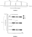
- the horizontal direction is a frequency axis, and the vertical arrows represent signals transmitted at particular frequencies.
- the upper part of the Figure shows the raster pattern 50 for a 4G carrier (Band B1) with relatively fine raster locations 51 at fixed 100kHz intervals.
- Indicated at 100 is a raster pattern 100 for a 5G carrier (Band B2) consists of a coarse raster indicated by the solid arrows 101, with some additional possible carrier locations with a fine raster around the coarse locations (as shown by the dashed arrows 102).
- two raster spacings may be employed simultaneously in the same frequency span. This allows for some fine adjustment without too many different possible frequencies to search.
- the system information design in LTE can be viewed as a tiered system by jointly considering the importance of the information, the sequence of the information (logically information A should be obtained before acquiring information B) and the corresponding transmission overhead.
- some crucial information is included into the Master Information Block (MIB) and broadcasted by the BS (called eNB in LTE) through PBCH (LTE Physical Broadcast Channel), using the 6 RBs (Resource Block) in the middle of the system bandwidth where PSS and SSS are also located.
- MIB Master Information Block
- PBCH LTE Physical Broadcast Channel
- 6 RBs Resource Block
- the system bandwidth has only a few possible settings with a range from 1.4 MHz to 20 MHz but a terminal has to support all possible settings, i.e., any particular setting deployed by the system.
- a terminal By broadcasting PBCH, PSS and SSS in the middle of the system bandwidth, a terminal will always be able to find synchronization signals and MIB no matter what the system bandwidth is, i.e., the detection of synchronization signal and MIB is independent of bandwidth.
- the synchronization signal and MIB design implies the following relationship between them: within the system bandwidth there is one and only one frequency domain location where PSS exists; one PSS is accompanied by one SSS signal in the same location in the frequency domain.
- the location of the MIB in the frequency domain is bounded by the 6 RBs in the middle of the system bandwidth which is indicated by the PSS.
- a 5G/NR system has many different properties compared with those of LTE, for example as mentioned before, a huge chunk of spectrum may be allocated for the NR system bandwidth (or equivalent) and the bandwidth supported by a particular terminal could be smaller than the corresponding system bandwidth.
- the PSS/SSS may also act as reference signals for demodulation of PBCH and/or act as reference signals for measurements used in Radio Resource Management (RRM).
- RRM measurements such as Reference Signal Received Power (RSRP) or Reference Signal Received Quality (RSRQ) may be made by the UE and used as a basis for cell selection and/or reported to the network to enable the appropriated handovers to new cells.
- RSRP Reference Signal Received Power
- RSRQ Reference Signal Received Quality
- a terminal wishes to synchronize with a cell provided by an operator in a particular frequency span.
- a default numerology will be associated with the frequency span, for example as shown in Table 2 above.
- a channel raster value used by the cell will be determined by the numerology.
- a channel raster is a set of locations in the frequency domain where a signal or channel (or more precisely a carrier wave thereof) can be located, and the term "channel raster value" denotes the step size or spacing between these frequency locations.
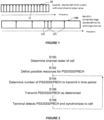
- step S102 possible resources for PSS/SSS/PBCH are defined.
- these may comprise all the raster locations across the frequency span as defined by the channel raster value. If a subset of the available raster locations is used, these should preferably be distributed over the whole frequency span for facilitating measurements (see below).
- Such locations will normally be predefined as part of the system implementation, but may be varied from time to time and instructed by higher-level signalling to a base station or equivalent such as a so-called gNB (next generation NodeB), which controls a Transmission/Reception Point (TRP) providing the cell.
- gNB next generation NodeB
- Step 104 is performed at the cell (base station) level and involves determining how many of the possible resources to use for actual transmission of PSS/SSS/PBCH, in other words how many instances of each of PSS, SSS and PBCH are required. In other words the number of transmissions within a predetermined time period (such as a frame) is determined, and factors to be considered in this determination relate to the deployment scenario, including the presence of neighbouring cells possibly causing interference, number and range of terminals etc. In addition to the number of instances, the actual locations are also determined. Regarding the possible resources in the frequency domain as a list arranged in order of frequency, if M PSS are required then the first M locations may be chosen for example. In practice, two or three instances in the frequency domain may be sufficient.
- a gNB may simply use the next available resource in the list.
- the respective number of instances of each of PSS, SSS and PBCH may differ as explained below.
- the operator merely needs to ensure that at least one PSS/SSS/PBCH is transmitted within the whole frequency span.
- step S106 the cell transmits PSS/SSS/PBCH in a number of instances, and in the resources previously determined.
- a terminal performs scanning by searching for a synchronization sequence in locations corresponding to the channel raster value, in a manner corresponding to the known use of PSS/SSS outlined in the introduction.
- the terminal may be configured in advance with the channel raster value and the synchronization signals to search for.
- the terminal becomes synchronized to the cell.
- the flow returns to step S104 allowing the process to be repeated for a next time period, such as a frame or multiple frames.
- the gNB will again transmit PSS/SSS/PBCH in a subsequent time frame, possibly in a different number of instances following a fresh determination of the numbers of transmissions required, allowing other terminals to synchronize with the cell.
- signals such as PSS/SSS/PBCH are not necessarily transmitted at the same locations in the time domain (i.e. not necessarily simultaneously), and the resource used may have flexible or pre-determined time domain locations within a suitable time frame such as slot, subframe or radio frame.
- Embodiments will now be described with reference to embodiments based on a 5G/NR system which is assumed to share many characteristics with LTE.
- the following embodiments involve transmission of multiple PSS within the system bandwidth of a cell (also referred to here as a "frequency span", since the concept of system bandwidth in LTE may be modified for use in NR).
- a first embodiment has PSS transmissions for a cell in multiple locations within the frequency domain.
- the PSS transmissions are not necessarily uniformly spaced in the frequency domain.
- the possible frequency domain locations of PSS would be indicated by a channel raster whose value may depend on the frequency span (system bandwidth) or the spectrum location or both. It may be possible to have multiple channel raster values within one frequency span and it is also possible that these PSS locations in the frequency domain are indicated by channel raster with different step values.
- multiple channel raster values could be used by one cell, allowing a UE to perform a quick search (using larger channel raster) during its initial search and then perform a refined search (maybe based on the information obtained through the first search); this can reduce the complexity and speed up the initial search process.
- multiple possible PSS locations can be according to a channel raster with a uniform step value within a particular frequency range/span.
- Figure 3 where multiple PSS are transmitted at locations 111 indicated by one particular channel raster within a frequency range.
- the upward arrows show the possible locations of PSS with the third and fifth possible locations 112 unused in this example.
- Figure 4 shows the same idea with resource allocations for the respective PSS in time and frequency domains, where PSS is transmitted at each of locations 111, and possible locations 112 are not selected in this example.
- instances of SSS and PBCH corresponding to each PSS are also transmitted at the same frequencies; thus, the same numbers of PSS/SSS/PBCH are transmitted.
- the shaded rectangles representing PSS, SSS and PBCH respectively are schematic and do not necessarily represent the size of resource needed to transmit each signal or channel. However, it will significantly reduce the blind detection burden of a UE if all PSS/SSS have the same amount of time/frequency resource.
- the gaps shown between PSS/SSS/PBCH do not necessarily represent the size of any time domain offset between these signals.
- Such a time offset could also be zero (e.g. one or more of PSS/SSS/PBCH could be transmitted simultaneously).
- one or more of the signals could share the same resource or be transmitted at different frequency domain raster locations, or with a pre-determined frequency offset from a raster location.
- the different PSS/SSS/PBCH instances can be received by UEs with different bandwidth capabilities as shown in Figure 5 .
- a terminal is not mandated to support all available system bandwidths.
- UE1 with wideband capability as indicated at 121 can receive multiple instances of PSS/SSS/PBCH simultaneously, transmitted at both frequency domain locations 111, while UE3 having a narrower receiving capability indicated by 123 can only receive one instance at a time.
- UE2 is shown operating at a frequency range 122 where there is no PSS/SSS/PBCH, only an unselected location 112. UE2 would need to be retuned to one or other of locations 111 in order to receive either instance of PSS/SSS/PBCH actually transmitted.
- One possible feature in NR is to allow a UE to operate in a wide bandwidth by using two or more receiver chains with narrow bandwidth, as shown in Figure 6 .
- the wide bandwidth is indicated at 124 and allows the UE to detect both instances of PSS/SSS/PBCH at frequency domain locations 111.
- the wide bandwidth is provided by twin receiver chains in adjacent narrow bandwidths.
- Such a mode of operation might lead to a discontinuity in the transmission path in the region of transition from one receiver chain to the other, e.g. if the two receiver chains have different phase and/or amplitude characteristics. Tracking any phase or amplitude differences would be facilitated by transmission of suitable reference signals in the frequency ranges covered by each receiver chain. PSS/SSS could act as reference signals for this purpose.
- advantages of multiple PSS and/or SSS and/or PBCH transmissions include the following.
- the first scenario is that a terminal has some pre-configured cell search information about where to find synchronization signals during the initial access process. Under this scenario the gain on cell search time reduction is limited.
- the second scenario is that a terminal does not have or does not have proper pre-configured cell search information. Under this scenario the cell search time could be significantly reduced by introducing multiple PSS. For example if a terminal searches a particular frequency range from one end of this frequency range to the other end, having multiple PSS over the whole frequency range may significantly reduce the search time, especially when PSSs are transmitted near the upper and lower bounds of this frequency range.
- PSS/SSS/PBCH transmissions in different regions over the operating bandwidth will allow frequency diversity gain (improving the chances of receiving PSS/SSS/PBCH at one or other frequency). This could improve the probability of correct cell identification based on PSS/SSS, and the reliability of reception of PBCH.
- the UE would ideally need to know the frequency domain locations of the different transmissions.
- a terminal may not support the whole operating bandwidth.
- the NR specification is unlikely to mandate a terminal to use a particular frequency range within the system bandwidth.
- a terminal with limited bandwidth capability could have a choice of more than one part of the spectrum and still receive PSS/SSS/PBCH, such as UE3 in Figure 5 .
- a terminal might use a frequency range where no PSS (or SSS and PBCH) is transmitted in this frequency range (such as UE2 in Figure 5 ); this terminal may need to frequently retune to another frequency region in order to detect synchronization signals or PBCH (before typically retuning again back to its original frequency).
- the RF retune may require a terminal to create a gap on transmission/reception, therefore reducing its throughput performance.
- FIG. 7 illustrates the above point.
- the resources in which PSS/SSS are not transmitted can be used to transmit data.
- UE1 having a wide receiving bandwidth 121 can receive some data and PSS/SSS at the same time.
- UE2's limited receiving bandwidth 122 is shown as tuned to data region 131; if it is retuned to get PSS/SSS, will not obtain data transmitted in region 131, on the other hand in the region of the nearby PSS/SSS there will not be any data scheduled to UE2.
- retuning to obtain PSS/SSS/PBCH followed by tuning back to the original frequency will be required.
- a UE After a UE has connected to the network, it may continue to detect PSS/SSS for the purpose of measurements, treating PSS/SSS as reference signals.
- PSS/SSS are used for RRM measurements
- multiple PSS/SSS will enable UEs to make corresponding RRM measurements reflecting the channel characteristics over a wider bandwidth than conventional PSS/SSS.
- DMRS of PBCH DeModulation Reference Signals
- DMRS of PBCH there may be a special DMRS signal mainly used for PBCH detection. Therefore if PBCH are transmitted at different frequency location, there are more PBCH DMRS to be used for RRM purposes.
- each PBCH contains identical information, but the other characteristics of the PBCH could be different, such as different scrambling codes which would enable the respective PBCH to carry different information.
- each PBCH may contain different information, for example a list or other indication of the existence of locations of the additional PSS/SSS/PBCH in the same frequency span (for simplicity, the list of locations could include that of the transmitting PBCH itself).
- the relationship (mapping) between PSS and /or SSS and/or PBCH is not restricted to a one-to-one mapping format (as applies in LTE), allowing more flexibility such as many-to-one or one-to-many mappings.
- mapping between PSS and SSS can be that M PSS are mapped to N SSS where M ⁇ 1 and N ⁇ 1; M can either ⁇ N or ⁇ N.
- the mapping relationship can be by Frequency-Division Multiplexing, FDM, Time-Division Multiplexing, TDM or both FDM and TDM applied simultaneously.
- mappings between SSS and PBCH can be devised.
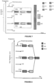
- a second embodiment based on the first embodiment we consider the case where one SSS corresponds to each PSS, but multiple SSS are mapped to one PBCH, as shown in Figure 8 .
- This has the advantage that PBCH transmission uses less overhead, and generates less interference to other cells than in the first embodiment, but RRM measurements based on PSS/SSS can still be carried out over a wide bandwidth.
- a UE might identify the presence of PSS/SSS without a corresponding PBCH. The UE may then assume that the PBCH is located at some other frequency.
- the PBCH may be located at a frequency (on a raster) which does not have a corresponding PSS and/or SSS transmission. This could be one of the unused locations 112 in Figure 8 , but need not be (in other words, PBCH could be on another raster from that shown by the arrows).
- a third embodiment based on the second embodiment considers the case where multiple PSS mapped to one SSS and one PBCH, as shown in Figure 9 .
- all of PSS/SSS/PBCH are transmitted at frequency location 111a, whilst only PSS is transmitted at each of locations 111b and 111c.
- This further reduces the overhead compared with the second embodiment, due to less resource used for transmission of SSS.
- wide band RRM measurements would need to rely on PSS (or some other signal) rather than on SSS, since SSS is only transmitted in one location in this example.
- measurement based on PSS is more likely to reflect the real radio conditions on a wide frequency range.
- the number of transmissions (instances) of any of PSS/SSS/PBCH can be changed with time, based on gNB configuration, providing that at any time instance, for the cell to be detectable, at least there should always be one PSS/SSS/PBCH being transmitted.
- This flexibility will allow the gNB to get a better tradeoff between synchronization signal overhead (and corresponding interference to other cells) and the system performance. For example, if cell acquisition by cell search is not a high priority and there are no UEs served by the cell with wideband capability, a single PSS/SSS/PBCH could be sufficient.
- the configuration may be changed every predetermined time period, such as multiples of a frame.
- mapping between PSS, SSS and PBCH could also be changed with time, for example switching between the first, second and third embodiments.
- FIG. 10 is a block diagram illustrating an example of a terminal 10 to which the present invention may be applied.
- the terminal 10 may include any type of device which may be used in a wireless communication system described above and may include cellular (or cell) phones (including smartphones), personal digital assistants (PDAs) with mobile communication capabilities, laptops or computer systems with mobile communication components, and/or any device that is operable to communicate wirelessly.
- the terminal 10 includes at least one transmitter/receiver unit 804 (each providing one receiver chain as mentioned above) connected to at least one antenna 802 (together defining a communication unit) and a controller 806 having access to memory in the form of a storage medium 808.
- the controller 806 may be, for example, a microprocessor, digital signal processor (DSP), application-specific integrated circuit (ASIC), field-programmable gate array (FPGA), or other logic circuitry programmed or otherwise configured to perform the various functions described above, including detecting PSS/SSS/PBCH for the purposes of cell search and synchronization.
- DSP digital signal processor
- ASIC application-specific integrated circuit
- FPGA field-programmable gate array
- the various functions described above may be embodied in the form of a computer program stored in the storage medium 808 and executed by the controller 806.
- the transmission/reception unit 804 is arranged, under control of the controller 806, to receive synchronization signals from cells, and subsequently to receive PBCH as discussed previously.
- the storage medium 808 stores the synchronization information so obtained.
- FIG 11 is a block diagram illustrating an example of a base station (e.g., gNB) 20 responsible for one or more cells.
- the base station includes transmitter/receiver unit(s) 904 connected to at least one antenna 902 (together defining a communication unit) and a controller 906.
- the controller may be, for example, a microprocessor, DSP, ASIC, FPGA, or other logic circuitry programmed or otherwise configured to perform the various functions described above, including determining how many PSS/SSS/PBCH are transmitted and in which locations, as mentioned earlier with respect to Figure 2 .
- the various functions described above may be embodied in the form of a computer program stored in the storage medium 908 and executed by the controller 906.
- the transmission/reception unit 904 is responsible for broadcasting synchronization signals, PBCH and so forth, under control of the controller 906.
- the mapping does not necessarily involve transmitting all of PSS/SSS/PBCH at the same frequency locations.
- the mappings may involve FDM, therefore, with respect to Figure 8 , for example PBCH could be transmitted at a different frequency location from PSS/SSS.
- a cell is provided by a "beam" which is one of multiple beams provided from a transmission/reception point via digital beamforming. Since the present invention focuses on the time/frequency domain and beams are in the spatial domain, the present invention can also be applied to such multiple beams. A simple extension is to apply the measures taken in the time/frequency domain in any of the above embodiments, to each spatial domain (beam). Broadcasting of PSS/SSS/PBCH as referred to above includes transmitting them on any one or more of such beams, including swept beams.
- the term "cell” is therefore to be interpreted broadly and includes parts of a cell, a beam, and the coverage area of an access point, transmission point or other network node.
- the invention is equally applicable to FDD and TDD systems, and to mixed TDD/FDD implementations (i.e., not restricted to cells of the same FDD/TDD type).
- References in the claims to a "terminal" are intended to cover any kind of user device, subscriber station, mobile terminal and the like and are not restricted to the UE of LTE.
- the invention also provides a computer program or a computer program product for carrying out any of the methods described herein, and a computer readable medium having stored thereon a program for carrying out any of the methods described herein.
- a computer program embodying the invention may be stored on a computer-readable medium, or it may, for example, be in the form of a signal such as a downloadable data signal provided from an Internet website, or it may be in any other form.
- embodiments of the present invention can provide frequency diversity gain for PSS detection, reduce search time during initial access, and improve RRM measurements, with the possibility of control over overhead and interference to other cells.
Landscapes
- Engineering & Computer Science (AREA)
- Signal Processing (AREA)
- Computer Networks & Wireless Communication (AREA)
- Databases & Information Systems (AREA)
- Mobile Radio Communication Systems (AREA)
Claims (17)
- Verfahren zur Zellsuche und -synchronisation, das durch eine Basisstation (20) in einem Drahtloskommunikationssystem durchgeführt wird, das mindestens eine Zelle bereitstellt, die durch die Basisstation (20) gesteuert wird und eine Frequenzspanne im Frequenzbereich aufweist, wobei das Verfahren umfasst:Definieren (S102) einer Vielzahl von Ressourcen (111, 112) für eine besagte Zelle innerhalb des Frequenzbereichs und innerhalb eines definierten Zeitrahmens zum Übertragen von Instanzen eines Synchronisationssignals, das eine oder mehrere Instanzen eines primären Synchronisationssignals, PSS, und eine oder mehrere Instanzen eines sekundären Synchronisationssignals, SSS, umfasst, wobei eine Ressource einer Position im Frequenzbereich und einer Position im Zeitbereich entspricht;Bestimmen (S104), wie viele Instanzen jeweils von PSS und SSS innerhalb eines vorgegebenen Zeitraums des definierten Zeitrahmens erforderlich sind; undÜbertragen (S106) der bestimmten Anzahl von Instanzen der PSS und SSS in der definierten Vielzahl von Ressourcen (111, 112), wobei die Vielzahl von Ressourcen (111, 112) unterschiedliche Positionen im Frequenzbereich und gleiche oder unterschiedliche Positionen im Zeitbereich aufweist.
- Verfahren nach Anspruch 1, wobei die Anzahl der Instanzen von einem Zeitrahmen zu einem anderen Zeitrahmen variieren kann.
- Verfahren nach Anspruch 1 oder 2, wobei eines oder mehrere der sekundären Synchronisationssignale, SSS, durch das Endgerät (10) verwendet werden, um weitere Informationen über die Zelle zu erlangen, wobei das Verfahren ferner Definieren der möglichen Ressourcen (111, 112) zur Übertragung eines sekundären Synchronisationssignals, SSS, umfasst, derart, dass eine vorgegebene Beziehung zwischen einer Ressource, in der ein primäres Synchronisationssignal, PSS, übertragen wird, und mindestens einer Ressource, in der ein sekundäres Synchronisationssignal, SSS, übertragen wird, besteht.
- Verfahren nach Anspruch 3, wobei das Definieren Bereitstellen einer Abbildung einer ganzzahligen Anzahl M von Übertragungen des primären Synchronisationssignals, PSS, auf eine ganzzahlige Anzahl N von Übertragungen des sekundären Synchronisationssignals, SSS, beinhaltet, wobei M>=1, N>=1 und M >= N oder M <= N ist.
- Verfahren nach Anspruch 3 oder 4, wobei Übertragen des sekundären Synchronisationssignals, SSS, Bestimmen beinhaltet, wie viele der möglichen Ressourcen (111, 112) zum Übertragen des sekundären Synchronisationssignals, SSS, in dem Zeitrahmen zu verwenden sind, wobei die Anzahl der Instanzen des sekundären Synchronisationssignals, SSS, von einem Zeitrahmen zu einem anderen Zeitrahmen variieren kann.
- Verfahren nach Anspruch 3, 4 oder 5, ferner umfassend Übertragen eines Rundfunkkanals, PBCH, auf einer oder mehreren Ressourcen (111) innerhalb der Frequenzspanne, wobei das Verfahren ferner Definieren möglicher Ressourcen (111, 112) für den Rundfunkkanal, PBCH, umfasst, derart, dass eine vorgegebene Beziehung zwischen einer Ressource, auf der das sekundäre Synchronisationssignal, SSS, übertragen wird, und mindestens einer Ressource besteht, auf der der Rundfunkkanal, PBCH, übertragen wird.
- Verfahren nach Anspruch 6, wobei das Definieren Bereitstellen einer Abbildung zwischen einer ganzzahligen Anzahl N von Übertragungen der sekundären Synchronisationssignale, SSS, und einer ganzzahligen Anzahl P von Übertragungen des Rundfunkkanals, PBCH, beinhaltet, wobei N>=1, P>=1 und N >= P oder N <= P ist.
- Verfahren nach Anspruch 3, 4 oder 5, ferner umfassend Übertragen eines Rundfunkkanals, PBCH, in einer oder mehreren Ressourcen (111) innerhalb der Frequenzspanne, wobei das Verfahren ferner Definieren möglicher Ressourcen (111, 112) für den Rundfunkkanal, PBCH, umfasst, derart, dass eine vorgegebene Beziehung zwischen einer Ressource, auf der das primäre Synchronisationssignal, PSS, übertragen wird, und mindestens einer Ressource besteht, auf der der Rundfunkkanal, PBCH, übertragen wird.
- Verfahren nach Anspruch 6, 7 oder 8, wobei das Übertragen des Rundfunkkanals, PBCH, Bestimmen beinhaltet, wie viele der möglichen Ressourcen (111, 112) für den Rundfunkkanal, PBCH, in dem Zeitrahmen zu verwenden sind, wobei die Anzahl der für die Übertragung des Rundfunkkanals, PBCH, verwendeten Ressourcen von einem Zeitrahmen zu einem anderen Zeitrahmen variieren kann.
- Verfahren nach einem der Ansprüche 6 bis 9, wobei der Rundfunkkanal, PBCH, in einer Vielzahl von Ressourcen (111) innerhalb der Frequenzspanne übertragen wird und in jeder der Ressourcen (111) ein identischer Inhalt übertragen wird.
- Verfahren nach einem der Ansprüche 6 bis 10, wobei das Übertragen mehrere Instanzen von mindestens einem der folgenden bereitstellt:das primäre Synchronisationssignal, PSS;das sekundäre Synchronisationssignal SSS; undder Rundfunkkanal, PBCH.
- Verfahren nach einem der vorhergehenden Ansprüche, wobei das System mindestens ein Kanalraster aufweist und dasselbe Kanalraster verwendet wird, um alle Frequenzbereichspositionen innerhalb der Frequenzspanne zu definieren.
- Verfahren nach einem der vorhergehenden Ansprüche, wobei die Ressourcen (111, 112) im Wesentlichen über die gesamte durch die Zelle verwendete Frequenzspanne verteilt sind.
- Verfahren nach einem der vorhergehenden Ansprüche, wobei das Definieren auf einer Numerologie basiert, die auf die Frequenzspanne der Zelle anwendbar ist.
- Basisstation (20) zur Verwendung in einem Drahtloskommunikationssystem, wobei die Basisstation (20) mindestens eine Zelle steuert, die eine Frequenzspanne im Frequenzbereich aufweist, wobei die Basisstation (20) eingerichtet ist zum:Definieren einer Vielzahl von Ressourcen (111, 112) für die Zelle innerhalb des Frequenzbereichs und innerhalb eines definierten Zeitrahmens zum Übertragen von Instanzen eines Synchronisationssignals, das eine oder mehrere Instanzen eines primären Synchronisationssignals, PSS, und eine oder mehrere Instanzen eines sekundären Synchronisationssignals, SSS, umfasst, wobei eine Ressource einer Position im Frequenzbereich und einer Position im Zeitbereich entspricht;Bestimmen, wie viele Instanzen jeweils von PSS und SSS innerhalb eines vorgegebenen Zeitraums des definierten Zeitrahmens erforderlich sind; undBewirken, dass die bestimmte Anzahl von Instanzen der PSS und SSS in der definierten Vielzahl von Ressourcen (111, 112) übertragen wird, wobei die Vielzahl von Ressourcen (111, 112) unterschiedliche Positionen im Frequenzbereich und gleiche oder unterschiedliche Positionen im Zeitbereich aufweist.
- Endgerät (10) zur Verwendung in einem Drahtloskommunikationssystem, das mindestens eine Zelle mit einer Frequenzspanne im Frequenzbereich bereitstellt, wobei das Endgerät (10) eingerichtet ist zum:Bestimmen einer Vielzahl von Ressourcen (111, 112) für die Zelle innerhalb des Frequenzbereichs und innerhalb eines definierten Zeitrahmens für den möglichen Empfang von Instanzen eines Synchronisationssignals, das eine oder mehrere Instanzen eines primären Synchronisationssignals, PSS, und eine oder mehrere Instanzen eines sekundären Synchronisationssignals, SSS, umfasst, wobei eine Ressource einer Position im Frequenzbereich und einer Position im Zeitbereich entspricht; undDurchführen einer Zellsuche durch Erfassen der durch die Zelle übertragenen Instanzen der PSS und SSS in der definierten Vielzahl von Ressourcen (111, 112), wobei die Vielzahl von Ressourcen (111, 112) unterschiedliche Positionen im Frequenzbereich und gleiche oder unterschiedliche Positionen im Zeitbereich aufweist.
- Drahtloskommunikationssystem, umfassend die Basisstation nach Anspruch 15 und das Endgerät nach Anspruch 16.
Priority Applications (6)
| Application Number | Priority Date | Filing Date | Title |
|---|---|---|---|
| EP17169137.1A EP3399809B1 (de) | 2017-05-02 | 2017-05-02 | Synchronisationssignale in 5g |
| JP2019557398A JP7113029B2 (ja) | 2017-05-02 | 2018-03-20 | 5gにおける同期信号 |
| PCT/EP2018/057079 WO2018202355A1 (en) | 2017-05-02 | 2018-03-20 | Synchronization signals in 5g |
| US16/660,329 US11477742B2 (en) | 2017-05-02 | 2019-10-22 | Synchronization signals in 5G |
| JP2021128160A JP7205582B2 (ja) | 2017-05-02 | 2021-08-04 | 5gにおける同期信号 |
| US17/946,150 US11800468B2 (en) | 2017-05-02 | 2022-09-16 | Synchronization signals in 5G |
Applications Claiming Priority (1)
| Application Number | Priority Date | Filing Date | Title |
|---|---|---|---|
| EP17169137.1A EP3399809B1 (de) | 2017-05-02 | 2017-05-02 | Synchronisationssignale in 5g |
Publications (2)
| Publication Number | Publication Date |
|---|---|
| EP3399809A1 EP3399809A1 (de) | 2018-11-07 |
| EP3399809B1 true EP3399809B1 (de) | 2024-07-17 |
Family
ID=58671423
Family Applications (1)
| Application Number | Title | Priority Date | Filing Date |
|---|---|---|---|
| EP17169137.1A Active EP3399809B1 (de) | 2017-05-02 | 2017-05-02 | Synchronisationssignale in 5g |
Country Status (4)
| Country | Link |
|---|---|
| US (2) | US11477742B2 (de) |
| EP (1) | EP3399809B1 (de) |
| JP (2) | JP7113029B2 (de) |
| WO (1) | WO2018202355A1 (de) |
Families Citing this family (8)
| Publication number | Priority date | Publication date | Assignee | Title |
|---|---|---|---|---|
| US11229052B2 (en) * | 2017-03-28 | 2022-01-18 | Intel Corporation | Processes and methods to enable downlink data transmission over wide bandwidth for the cell edge station |
| US10868626B2 (en) * | 2018-02-21 | 2020-12-15 | Mediatek Inc. | Synchronization signal block raster shift in mobile communications |
| CN109347594B (zh) * | 2018-11-20 | 2020-05-29 | 南京迅测科技有限公司 | 基于信号分析仪平台实现5g信号小区搜索的方法 |
| CN109587784B (zh) * | 2018-12-27 | 2020-04-14 | 广州供电局有限公司 | 时钟同步通信系统及其时间同步方法 |
| US11528657B1 (en) * | 2021-06-18 | 2022-12-13 | Nokia Technologies Oy | Intelligent reflecting surface configuration |
| CN115696552B (zh) * | 2022-10-25 | 2023-04-14 | 上海山源电子科技股份有限公司 | 5g同步信号处理方法及装置 |
| US20240298279A1 (en) * | 2023-03-02 | 2024-09-05 | Qualcomm Incorporated | Wideband synchronization signal block (ssb) using phase-coded frequency-modulated continuous-wave (pc-fmcw) for joint communications and sensing (jcs) |
| WO2026030967A1 (en) * | 2024-08-07 | 2026-02-12 | Mediatek Singapore Pte. Ltd. | Schemes for synchronization raster related issues |
Family Cites Families (25)
| Publication number | Priority date | Publication date | Assignee | Title |
|---|---|---|---|---|
| FR2809554B1 (fr) * | 2000-05-23 | 2002-08-16 | Mitsubishi Electric Telecom Eu | Procede de synchronisation d'au moins une station mobile dans un reseau de telecommunication mobile ayant une structure de canal de synchronisation modifiee |
| DE10326336B4 (de) * | 2003-06-11 | 2006-06-29 | Infineon Technologies Ag | Vorrichtung und Verfahren zum zeitlichen Steuern der Verarbeitung eines Funksignals in einer Mobilstation |
| JP4440831B2 (ja) * | 2005-06-14 | 2010-03-24 | 株式会社エヌ・ティ・ティ・ドコモ | 基地局装置、送信方法及び通信システム |
| US7706352B2 (en) * | 2005-11-01 | 2010-04-27 | Nokia Corporation | Multicarrier pilot structure for reliable frame detection |
| KR101259100B1 (ko) * | 2005-11-04 | 2013-04-26 | 엘지전자 주식회사 | Ofdm 또는 ofdma 무선 이동통신 시스템에서의초기 동기를 위한 신호 전송 방법, 초기 동기 획득 방법 및이동통신용 단말 |
| KR100827064B1 (ko) * | 2006-01-18 | 2008-05-02 | 삼성전자주식회사 | Ofdm 기반 셀룰러 무선통신시스템의 동기 신호 송신 방법 및 장치 |
| US8649401B2 (en) * | 2007-05-01 | 2014-02-11 | Qualcomm Incorporated | Generation and detection of synchronization signal in a wireless communication system |
| WO2009054058A1 (ja) * | 2007-10-25 | 2009-04-30 | Fujitsu Limited | 送信方法、無線基地局および移動局 |
| CA2727066C (en) | 2008-08-04 | 2019-09-24 | Panasonic Corporation | Base station, terminal, band allocation method, and downlink data communication method |
| WO2011043411A1 (ja) * | 2009-10-07 | 2011-04-14 | 住友電気工業株式会社 | 基地局装置 |
| US9674842B2 (en) * | 2011-11-03 | 2017-06-06 | Kyocera Corporation | Communication control method, base station, and user terminal |
| US9681404B2 (en) * | 2012-07-05 | 2017-06-13 | Lg Electronics Inc. | Method and user equipment for synchronizing component carriers used in carrier aggregation |
| US9768925B2 (en) * | 2012-11-04 | 2017-09-19 | Lg Electronics Inc. | Method for transmitting/receiving synchronizing signals in wireless communication system and device therefor |
| US9917616B2 (en) * | 2013-01-17 | 2018-03-13 | Telefonaktiebolaget L M Ericsson (Publ) | Synchronization signal design for wireless devices in a long range extension mode |
| CN105075158B (zh) * | 2013-03-20 | 2018-02-13 | Lg 电子株式会社 | 在无线通信系统中使用设备对设备通信发送和接收信号的方法及其设备 |
| WO2014193010A1 (ko) * | 2013-05-31 | 2014-12-04 | 엘지전자 주식회사 | 무선 접속 시스템에서 인접 셀의 간섭을 제거하기 위한 제어 정보를 수신하는 방법 및 장치 |
| SG11201602473SA (en) * | 2013-11-27 | 2016-04-28 | Ericsson Telefon Ab L M | Network node, wireless device, methods therein, for sending and detecting, respectively, synchronization signal and an associated information |
| EP3075089B1 (de) * | 2013-11-27 | 2021-09-08 | Telefonaktiebolaget LM Ericsson (publ) | Senden und erkennen von synchronisationssignalen sowie zugehörige informationsnachricht |
| EP3133881B1 (de) * | 2014-05-04 | 2019-03-20 | Huawei Technologies Co., Ltd. | Verfahren, einrichtung und vorrichtung zum senden/empfangen von synchronisationssignalen |
| US20160044710A1 (en) * | 2014-08-07 | 2016-02-11 | Electronics And Telecommunications Research Institute | Transmission/reception method of base station, d2d communication method, and apparatus supporting the d2d communication method |
| KR102341299B1 (ko) * | 2015-02-11 | 2021-12-21 | 삼성전자주식회사 | 셀 탐색 및 주파수 옵셋 추정 방법 및 장치 |
| CN107223355A (zh) * | 2015-03-17 | 2017-09-29 | 瑞典爱立信有限公司 | 无线通信网络中的同步 |
| US10165536B2 (en) * | 2015-06-19 | 2018-12-25 | Qualcomm Incorporated | System scanning and acquisition |
| US10206189B2 (en) * | 2015-07-27 | 2019-02-12 | Telefonaktiebolaget Lm Ericsson (Publ) | Narrowband LTE cell search |
| GB2555790A (en) | 2016-11-08 | 2018-05-16 | Fujitsu Ltd | Cell search and synchronization in 5G |
-
2017
- 2017-05-02 EP EP17169137.1A patent/EP3399809B1/de active Active
-
2018
- 2018-03-20 WO PCT/EP2018/057079 patent/WO2018202355A1/en not_active Ceased
- 2018-03-20 JP JP2019557398A patent/JP7113029B2/ja active Active
-
2019
- 2019-10-22 US US16/660,329 patent/US11477742B2/en active Active
-
2021
- 2021-08-04 JP JP2021128160A patent/JP7205582B2/ja active Active
-
2022
- 2022-09-16 US US17/946,150 patent/US11800468B2/en active Active
Also Published As
| Publication number | Publication date |
|---|---|
| JP2020519072A (ja) | 2020-06-25 |
| JP2021184629A (ja) | 2021-12-02 |
| US11800468B2 (en) | 2023-10-24 |
| US20200053674A1 (en) | 2020-02-13 |
| US20230007605A1 (en) | 2023-01-05 |
| WO2018202355A1 (en) | 2018-11-08 |
| US11477742B2 (en) | 2022-10-18 |
| EP3399809A1 (de) | 2018-11-07 |
| JP7205582B2 (ja) | 2023-01-17 |
| JP7113029B2 (ja) | 2022-08-04 |
Similar Documents
| Publication | Publication Date | Title |
|---|---|---|
| US11800468B2 (en) | Synchronization signals in 5G | |
| US11343784B2 (en) | Synchronization and broadcast signal design for 5G | |
| US20190253959A1 (en) | Cell Search and Synchronization in 5G | |
| US12302221B2 (en) | Communication system for communicating minimum system information | |
| CN114513795B (zh) | 用于新无线电频谱共享发现信号的先听后说的方法和装置 | |
| EP3487206A1 (de) | Messspaltkonfiguration für 5g | |
| KR102115840B1 (ko) | 롱텀 에볼루션(lte) 업링크 스펙트럼의 공유 | |
| CN110708153B (zh) | 在未许可射频频谱上的无线通信 | |
| CN111357377B (zh) | 用于介质共享的通用信道预留信号 | |
| EP3777442A1 (de) | Rundfunksignal mit erweiterter reichweite auf anfrage | |
| CN106664171B (zh) | 用于管理小区参考符号的传输的网络节点和方法 | |
| CN112243598A (zh) | 跨多个毗邻载波的同步频谱共享 | |
| US20180317212A1 (en) | Wireless Device and Network Node for a Wireless Communication System and Methods Thereof | |
| EP3487205A1 (de) | Messspaltkonfiguration für 5g | |
| CN112423377B (zh) | 用于管理小区参考符号的功率的网络节点和方法 |
Legal Events
| Date | Code | Title | Description |
|---|---|---|---|
| PUAI | Public reference made under article 153(3) epc to a published international application that has entered the european phase |
Free format text: ORIGINAL CODE: 0009012 |
|
| STAA | Information on the status of an ep patent application or granted ep patent |
Free format text: STATUS: THE APPLICATION HAS BEEN PUBLISHED |
|
| STAA | Information on the status of an ep patent application or granted ep patent |
Free format text: STATUS: REQUEST FOR EXAMINATION WAS MADE |
|
| AK | Designated contracting states |
Kind code of ref document: A1 Designated state(s): AL AT BE BG CH CY CZ DE DK EE ES FI FR GB GR HR HU IE IS IT LI LT LU LV MC MK MT NL NO PL PT RO RS SE SI SK SM TR |
|
| AX | Request for extension of the european patent |
Extension state: BA ME |
|
| 17P | Request for examination filed |
Effective date: 20181016 |
|
| RBV | Designated contracting states (corrected) |
Designated state(s): AL AT BE BG CH CY CZ DE DK EE ES FI FR GB GR HR HU IE IS IT LI LT LU LV MC MK MT NL NO PL PT RO RS SE SI SK SM TR |
|
| STAA | Information on the status of an ep patent application or granted ep patent |
Free format text: STATUS: EXAMINATION IS IN PROGRESS |
|
| 17Q | First examination report despatched |
Effective date: 20191119 |
|
| GRAP | Despatch of communication of intention to grant a patent |
Free format text: ORIGINAL CODE: EPIDOSNIGR1 |
|
| STAA | Information on the status of an ep patent application or granted ep patent |
Free format text: STATUS: GRANT OF PATENT IS INTENDED |
|
| INTG | Intention to grant announced |
Effective date: 20240315 |
|
| GRAS | Grant fee paid |
Free format text: ORIGINAL CODE: EPIDOSNIGR3 |
|
| GRAA | (expected) grant |
Free format text: ORIGINAL CODE: 0009210 |
|
| STAA | Information on the status of an ep patent application or granted ep patent |
Free format text: STATUS: THE PATENT HAS BEEN GRANTED |
|
| AK | Designated contracting states |
Kind code of ref document: B1 Designated state(s): AL AT BE BG CH CY CZ DE DK EE ES FI FR GB GR HR HU IE IS IT LI LT LU LV MC MK MT NL NO PL PT RO RS SE SI SK SM TR |
|
| REG | Reference to a national code |
Ref country code: GB Ref legal event code: FG4D |
|
| REG | Reference to a national code |
Ref country code: CH Ref legal event code: EP |
|
| REG | Reference to a national code |
Ref country code: DE Ref legal event code: R096 Ref document number: 602017083318 Country of ref document: DE |
|
| REG | Reference to a national code |
Ref country code: IE Ref legal event code: FG4D |
|
| REG | Reference to a national code |
Ref country code: LT Ref legal event code: MG9D |
|
| REG | Reference to a national code |
Ref country code: NL Ref legal event code: MP Effective date: 20240717 |
|
| PG25 | Lapsed in a contracting state [announced via postgrant information from national office to epo] |
Ref country code: PT Free format text: LAPSE BECAUSE OF FAILURE TO SUBMIT A TRANSLATION OF THE DESCRIPTION OR TO PAY THE FEE WITHIN THE PRESCRIBED TIME-LIMIT Effective date: 20241118 |
|
| REG | Reference to a national code |
Ref country code: AT Ref legal event code: MK05 Ref document number: 1705278 Country of ref document: AT Kind code of ref document: T Effective date: 20240717 |
|
| PG25 | Lapsed in a contracting state [announced via postgrant information from national office to epo] |
Ref country code: NL Free format text: LAPSE BECAUSE OF FAILURE TO SUBMIT A TRANSLATION OF THE DESCRIPTION OR TO PAY THE FEE WITHIN THE PRESCRIBED TIME-LIMIT Effective date: 20240717 |
|
| PG25 | Lapsed in a contracting state [announced via postgrant information from national office to epo] |
Ref country code: PT Free format text: LAPSE BECAUSE OF FAILURE TO SUBMIT A TRANSLATION OF THE DESCRIPTION OR TO PAY THE FEE WITHIN THE PRESCRIBED TIME-LIMIT Effective date: 20241118 Ref country code: NL Free format text: LAPSE BECAUSE OF FAILURE TO SUBMIT A TRANSLATION OF THE DESCRIPTION OR TO PAY THE FEE WITHIN THE PRESCRIBED TIME-LIMIT Effective date: 20240717 |
|
| PG25 | Lapsed in a contracting state [announced via postgrant information from national office to epo] |
Ref country code: NO Free format text: LAPSE BECAUSE OF FAILURE TO SUBMIT A TRANSLATION OF THE DESCRIPTION OR TO PAY THE FEE WITHIN THE PRESCRIBED TIME-LIMIT Effective date: 20241017 |
|
| PG25 | Lapsed in a contracting state [announced via postgrant information from national office to epo] |
Ref country code: FI Free format text: LAPSE BECAUSE OF FAILURE TO SUBMIT A TRANSLATION OF THE DESCRIPTION OR TO PAY THE FEE WITHIN THE PRESCRIBED TIME-LIMIT Effective date: 20240717 Ref country code: GR Free format text: LAPSE BECAUSE OF FAILURE TO SUBMIT A TRANSLATION OF THE DESCRIPTION OR TO PAY THE FEE WITHIN THE PRESCRIBED TIME-LIMIT Effective date: 20241018 Ref country code: PL Free format text: LAPSE BECAUSE OF FAILURE TO SUBMIT A TRANSLATION OF THE DESCRIPTION OR TO PAY THE FEE WITHIN THE PRESCRIBED TIME-LIMIT Effective date: 20240717 |
|
| PG25 | Lapsed in a contracting state [announced via postgrant information from national office to epo] |
Ref country code: BG Free format text: LAPSE BECAUSE OF FAILURE TO SUBMIT A TRANSLATION OF THE DESCRIPTION OR TO PAY THE FEE WITHIN THE PRESCRIBED TIME-LIMIT Effective date: 20240717 |
|
| PG25 | Lapsed in a contracting state [announced via postgrant information from national office to epo] |
Ref country code: LV Free format text: LAPSE BECAUSE OF FAILURE TO SUBMIT A TRANSLATION OF THE DESCRIPTION OR TO PAY THE FEE WITHIN THE PRESCRIBED TIME-LIMIT Effective date: 20240717 |
|
| PG25 | Lapsed in a contracting state [announced via postgrant information from national office to epo] |
Ref country code: IS Free format text: LAPSE BECAUSE OF FAILURE TO SUBMIT A TRANSLATION OF THE DESCRIPTION OR TO PAY THE FEE WITHIN THE PRESCRIBED TIME-LIMIT Effective date: 20241117 Ref country code: AT Free format text: LAPSE BECAUSE OF FAILURE TO SUBMIT A TRANSLATION OF THE DESCRIPTION OR TO PAY THE FEE WITHIN THE PRESCRIBED TIME-LIMIT Effective date: 20240717 |
|
| PG25 | Lapsed in a contracting state [announced via postgrant information from national office to epo] |
Ref country code: HR Free format text: LAPSE BECAUSE OF FAILURE TO SUBMIT A TRANSLATION OF THE DESCRIPTION OR TO PAY THE FEE WITHIN THE PRESCRIBED TIME-LIMIT Effective date: 20240717 |
|
| PG25 | Lapsed in a contracting state [announced via postgrant information from national office to epo] |
Ref country code: ES Free format text: LAPSE BECAUSE OF FAILURE TO SUBMIT A TRANSLATION OF THE DESCRIPTION OR TO PAY THE FEE WITHIN THE PRESCRIBED TIME-LIMIT Effective date: 20240717 Ref country code: RS Free format text: LAPSE BECAUSE OF FAILURE TO SUBMIT A TRANSLATION OF THE DESCRIPTION OR TO PAY THE FEE WITHIN THE PRESCRIBED TIME-LIMIT Effective date: 20241017 |
|
| PG25 | Lapsed in a contracting state [announced via postgrant information from national office to epo] |
Ref country code: RS Free format text: LAPSE BECAUSE OF FAILURE TO SUBMIT A TRANSLATION OF THE DESCRIPTION OR TO PAY THE FEE WITHIN THE PRESCRIBED TIME-LIMIT Effective date: 20241017 Ref country code: PL Free format text: LAPSE BECAUSE OF FAILURE TO SUBMIT A TRANSLATION OF THE DESCRIPTION OR TO PAY THE FEE WITHIN THE PRESCRIBED TIME-LIMIT Effective date: 20240717 Ref country code: NO Free format text: LAPSE BECAUSE OF FAILURE TO SUBMIT A TRANSLATION OF THE DESCRIPTION OR TO PAY THE FEE WITHIN THE PRESCRIBED TIME-LIMIT Effective date: 20241017 Ref country code: LV Free format text: LAPSE BECAUSE OF FAILURE TO SUBMIT A TRANSLATION OF THE DESCRIPTION OR TO PAY THE FEE WITHIN THE PRESCRIBED TIME-LIMIT Effective date: 20240717 Ref country code: IS Free format text: LAPSE BECAUSE OF FAILURE TO SUBMIT A TRANSLATION OF THE DESCRIPTION OR TO PAY THE FEE WITHIN THE PRESCRIBED TIME-LIMIT Effective date: 20241117 Ref country code: HR Free format text: LAPSE BECAUSE OF FAILURE TO SUBMIT A TRANSLATION OF THE DESCRIPTION OR TO PAY THE FEE WITHIN THE PRESCRIBED TIME-LIMIT Effective date: 20240717 Ref country code: GR Free format text: LAPSE BECAUSE OF FAILURE TO SUBMIT A TRANSLATION OF THE DESCRIPTION OR TO PAY THE FEE WITHIN THE PRESCRIBED TIME-LIMIT Effective date: 20241018 Ref country code: FI Free format text: LAPSE BECAUSE OF FAILURE TO SUBMIT A TRANSLATION OF THE DESCRIPTION OR TO PAY THE FEE WITHIN THE PRESCRIBED TIME-LIMIT Effective date: 20240717 Ref country code: ES Free format text: LAPSE BECAUSE OF FAILURE TO SUBMIT A TRANSLATION OF THE DESCRIPTION OR TO PAY THE FEE WITHIN THE PRESCRIBED TIME-LIMIT Effective date: 20240717 Ref country code: BG Free format text: LAPSE BECAUSE OF FAILURE TO SUBMIT A TRANSLATION OF THE DESCRIPTION OR TO PAY THE FEE WITHIN THE PRESCRIBED TIME-LIMIT Effective date: 20240717 Ref country code: AT Free format text: LAPSE BECAUSE OF FAILURE TO SUBMIT A TRANSLATION OF THE DESCRIPTION OR TO PAY THE FEE WITHIN THE PRESCRIBED TIME-LIMIT Effective date: 20240717 |
|
| PG25 | Lapsed in a contracting state [announced via postgrant information from national office to epo] |
Ref country code: DK Free format text: LAPSE BECAUSE OF FAILURE TO SUBMIT A TRANSLATION OF THE DESCRIPTION OR TO PAY THE FEE WITHIN THE PRESCRIBED TIME-LIMIT Effective date: 20240717 Ref country code: SM Free format text: LAPSE BECAUSE OF FAILURE TO SUBMIT A TRANSLATION OF THE DESCRIPTION OR TO PAY THE FEE WITHIN THE PRESCRIBED TIME-LIMIT Effective date: 20240717 Ref country code: RO Free format text: LAPSE BECAUSE OF FAILURE TO SUBMIT A TRANSLATION OF THE DESCRIPTION OR TO PAY THE FEE WITHIN THE PRESCRIBED TIME-LIMIT Effective date: 20240717 |
|
| REG | Reference to a national code |
Ref country code: DE Ref legal event code: R097 Ref document number: 602017083318 Country of ref document: DE |
|
| PG25 | Lapsed in a contracting state [announced via postgrant information from national office to epo] |
Ref country code: EE Free format text: LAPSE BECAUSE OF FAILURE TO SUBMIT A TRANSLATION OF THE DESCRIPTION OR TO PAY THE FEE WITHIN THE PRESCRIBED TIME-LIMIT Effective date: 20240717 |
|
| PG25 | Lapsed in a contracting state [announced via postgrant information from national office to epo] |
Ref country code: CZ Free format text: LAPSE BECAUSE OF FAILURE TO SUBMIT A TRANSLATION OF THE DESCRIPTION OR TO PAY THE FEE WITHIN THE PRESCRIBED TIME-LIMIT Effective date: 20240717 |
|
| PG25 | Lapsed in a contracting state [announced via postgrant information from national office to epo] |
Ref country code: SK Free format text: LAPSE BECAUSE OF FAILURE TO SUBMIT A TRANSLATION OF THE DESCRIPTION OR TO PAY THE FEE WITHIN THE PRESCRIBED TIME-LIMIT Effective date: 20240717 |
|
| PLBE | No opposition filed within time limit |
Free format text: ORIGINAL CODE: 0009261 |
|
| STAA | Information on the status of an ep patent application or granted ep patent |
Free format text: STATUS: NO OPPOSITION FILED WITHIN TIME LIMIT |
|
| 26N | No opposition filed |
Effective date: 20250422 |
|
| PGFP | Annual fee paid to national office [announced via postgrant information from national office to epo] |
Ref country code: DE Payment date: 20250423 Year of fee payment: 9 |
|
| PGFP | Annual fee paid to national office [announced via postgrant information from national office to epo] |
Ref country code: GB Payment date: 20250423 Year of fee payment: 9 |
|
| PGFP | Annual fee paid to national office [announced via postgrant information from national office to epo] |
Ref country code: FR Payment date: 20250423 Year of fee payment: 9 |
|
| PG25 | Lapsed in a contracting state [announced via postgrant information from national office to epo] |
Ref country code: SE Free format text: LAPSE BECAUSE OF FAILURE TO SUBMIT A TRANSLATION OF THE DESCRIPTION OR TO PAY THE FEE WITHIN THE PRESCRIBED TIME-LIMIT Effective date: 20240717 |
|
| REG | Reference to a national code |
Ref country code: DE Ref legal event code: R081 Ref document number: 602017083318 Country of ref document: DE Owner name: 1FINITY INC., KAWASAKI-SHI, JP Free format text: FORMER OWNER: FUJITSU LIMITED, KAWASAKI-SHI, KANAGAWA, JP |
|
| REG | Reference to a national code |
Ref country code: CH Ref legal event code: H13 Free format text: ST27 STATUS EVENT CODE: U-0-0-H10-H13 (AS PROVIDED BY THE NATIONAL OFFICE) Effective date: 20251223 |
|
| REG | Reference to a national code |
Ref country code: GB Ref legal event code: 732E Free format text: REGISTERED BETWEEN 20251127 AND 20251203 |
|
| PG25 | Lapsed in a contracting state [announced via postgrant information from national office to epo] |
Ref country code: LU Free format text: LAPSE BECAUSE OF NON-PAYMENT OF DUE FEES Effective date: 20250502 |
|
| PG25 | Lapsed in a contracting state [announced via postgrant information from national office to epo] |
Ref country code: CH Free format text: LAPSE BECAUSE OF NON-PAYMENT OF DUE FEES Effective date: 20250531 |
|
| PG25 | Lapsed in a contracting state [announced via postgrant information from national office to epo] |
Ref country code: IT Free format text: LAPSE BECAUSE OF FAILURE TO SUBMIT A TRANSLATION OF THE DESCRIPTION OR TO PAY THE FEE WITHIN THE PRESCRIBED TIME-LIMIT Effective date: 20240717 |
|
| REG | Reference to a national code |
Ref country code: BE Ref legal event code: MM Effective date: 20250531 |
|
| PG25 | Lapsed in a contracting state [announced via postgrant information from national office to epo] |
Ref country code: MC Free format text: LAPSE BECAUSE OF FAILURE TO SUBMIT A TRANSLATION OF THE DESCRIPTION OR TO PAY THE FEE WITHIN THE PRESCRIBED TIME-LIMIT Effective date: 20240717 |
|
| PG25 | Lapsed in a contracting state [announced via postgrant information from national office to epo] |
Ref country code: IE Free format text: LAPSE BECAUSE OF NON-PAYMENT OF DUE FEES Effective date: 20250502 |
|
| PG25 | Lapsed in a contracting state [announced via postgrant information from national office to epo] |
Ref country code: BE Free format text: LAPSE BECAUSE OF NON-PAYMENT OF DUE FEES Effective date: 20250531 |