EP3400148B1 - Verfahren und system zur aktiven entladung der eingangskondensatoren in einer bordladevorrichtung für ein elektro- oder hybridfahrzeug - Google Patents
Verfahren und system zur aktiven entladung der eingangskondensatoren in einer bordladevorrichtung für ein elektro- oder hybridfahrzeug Download PDFInfo
- Publication number
- EP3400148B1 EP3400148B1 EP17702421.3A EP17702421A EP3400148B1 EP 3400148 B1 EP3400148 B1 EP 3400148B1 EP 17702421 A EP17702421 A EP 17702421A EP 3400148 B1 EP3400148 B1 EP 3400148B1
- Authority
- EP
- European Patent Office
- Prior art keywords
- stage
- switches
- ele
- red
- voltage
- Prior art date
- Legal status (The legal status is an assumption and is not a legal conclusion. Google has not performed a legal analysis and makes no representation as to the accuracy of the status listed.)
- Active
Links
Images




Classifications
-
- B—PERFORMING OPERATIONS; TRANSPORTING
- B60—VEHICLES IN GENERAL
- B60L—PROPULSION OF ELECTRICALLY-PROPELLED VEHICLES; SUPPLYING ELECTRIC POWER FOR AUXILIARY EQUIPMENT OF ELECTRICALLY-PROPELLED VEHICLES; ELECTRODYNAMIC BRAKE SYSTEMS FOR VEHICLES IN GENERAL; MAGNETIC SUSPENSION OR LEVITATION FOR VEHICLES; MONITORING OPERATING VARIABLES OF ELECTRICALLY-PROPELLED VEHICLES; ELECTRIC SAFETY DEVICES FOR ELECTRICALLY-PROPELLED VEHICLES
- B60L50/00—Electric propulsion with power supplied within the vehicle
- B60L50/40—Electric propulsion with power supplied within the vehicle using propulsion power supplied by capacitors
-
- B—PERFORMING OPERATIONS; TRANSPORTING
- B60—VEHICLES IN GENERAL
- B60L—PROPULSION OF ELECTRICALLY-PROPELLED VEHICLES; SUPPLYING ELECTRIC POWER FOR AUXILIARY EQUIPMENT OF ELECTRICALLY-PROPELLED VEHICLES; ELECTRODYNAMIC BRAKE SYSTEMS FOR VEHICLES IN GENERAL; MAGNETIC SUSPENSION OR LEVITATION FOR VEHICLES; MONITORING OPERATING VARIABLES OF ELECTRICALLY-PROPELLED VEHICLES; ELECTRIC SAFETY DEVICES FOR ELECTRICALLY-PROPELLED VEHICLES
- B60L53/00—Methods of charging batteries, specially adapted for electric vehicles; Charging stations or on-board charging equipment therefor; Exchange of energy storage elements in electric vehicles
-
- B—PERFORMING OPERATIONS; TRANSPORTING
- B60—VEHICLES IN GENERAL
- B60L—PROPULSION OF ELECTRICALLY-PROPELLED VEHICLES; SUPPLYING ELECTRIC POWER FOR AUXILIARY EQUIPMENT OF ELECTRICALLY-PROPELLED VEHICLES; ELECTRODYNAMIC BRAKE SYSTEMS FOR VEHICLES IN GENERAL; MAGNETIC SUSPENSION OR LEVITATION FOR VEHICLES; MONITORING OPERATING VARIABLES OF ELECTRICALLY-PROPELLED VEHICLES; ELECTRIC SAFETY DEVICES FOR ELECTRICALLY-PROPELLED VEHICLES
- B60L53/00—Methods of charging batteries, specially adapted for electric vehicles; Charging stations or on-board charging equipment therefor; Exchange of energy storage elements in electric vehicles
- B60L53/50—Charging stations characterised by energy-storage or power-generation means
- B60L53/55—Capacitors
-
- B—PERFORMING OPERATIONS; TRANSPORTING
- B60—VEHICLES IN GENERAL
- B60L—PROPULSION OF ELECTRICALLY-PROPELLED VEHICLES; SUPPLYING ELECTRIC POWER FOR AUXILIARY EQUIPMENT OF ELECTRICALLY-PROPELLED VEHICLES; ELECTRODYNAMIC BRAKE SYSTEMS FOR VEHICLES IN GENERAL; MAGNETIC SUSPENSION OR LEVITATION FOR VEHICLES; MONITORING OPERATING VARIABLES OF ELECTRICALLY-PROPELLED VEHICLES; ELECTRIC SAFETY DEVICES FOR ELECTRICALLY-PROPELLED VEHICLES
- B60L2270/00—Problem solutions or means not otherwise provided for
- B60L2270/20—Inrush current reduction, i.e. avoiding high currents when connecting the battery
-
- B—PERFORMING OPERATIONS; TRANSPORTING
- B60—VEHICLES IN GENERAL
- B60Y—INDEXING SCHEME RELATING TO ASPECTS CROSS-CUTTING VEHICLE TECHNOLOGY
- B60Y2200/00—Type of vehicle
- B60Y2200/90—Vehicles comprising electric prime movers
- B60Y2200/91—Electric vehicles
-
- B—PERFORMING OPERATIONS; TRANSPORTING
- B60—VEHICLES IN GENERAL
- B60Y—INDEXING SCHEME RELATING TO ASPECTS CROSS-CUTTING VEHICLE TECHNOLOGY
- B60Y2200/00—Type of vehicle
- B60Y2200/90—Vehicles comprising electric prime movers
- B60Y2200/92—Hybrid vehicles
-
- Y—GENERAL TAGGING OF NEW TECHNOLOGICAL DEVELOPMENTS; GENERAL TAGGING OF CROSS-SECTIONAL TECHNOLOGIES SPANNING OVER SEVERAL SECTIONS OF THE IPC; TECHNICAL SUBJECTS COVERED BY FORMER USPC CROSS-REFERENCE ART COLLECTIONS [XRACs] AND DIGESTS
- Y02—TECHNOLOGIES OR APPLICATIONS FOR MITIGATION OR ADAPTATION AGAINST CLIMATE CHANGE
- Y02T—CLIMATE CHANGE MITIGATION TECHNOLOGIES RELATED TO TRANSPORTATION
- Y02T10/00—Road transport of goods or passengers
- Y02T10/60—Other road transportation technologies with climate change mitigation effect
- Y02T10/70—Energy storage systems for electromobility, e.g. batteries
-
- Y—GENERAL TAGGING OF NEW TECHNOLOGICAL DEVELOPMENTS; GENERAL TAGGING OF CROSS-SECTIONAL TECHNOLOGIES SPANNING OVER SEVERAL SECTIONS OF THE IPC; TECHNICAL SUBJECTS COVERED BY FORMER USPC CROSS-REFERENCE ART COLLECTIONS [XRACs] AND DIGESTS
- Y02—TECHNOLOGIES OR APPLICATIONS FOR MITIGATION OR ADAPTATION AGAINST CLIMATE CHANGE
- Y02T—CLIMATE CHANGE MITIGATION TECHNOLOGIES RELATED TO TRANSPORTATION
- Y02T10/00—Road transport of goods or passengers
- Y02T10/60—Other road transportation technologies with climate change mitigation effect
- Y02T10/7072—Electromobility specific charging systems or methods for batteries, ultracapacitors, supercapacitors or double-layer capacitors
-
- Y—GENERAL TAGGING OF NEW TECHNOLOGICAL DEVELOPMENTS; GENERAL TAGGING OF CROSS-SECTIONAL TECHNOLOGIES SPANNING OVER SEVERAL SECTIONS OF THE IPC; TECHNICAL SUBJECTS COVERED BY FORMER USPC CROSS-REFERENCE ART COLLECTIONS [XRACs] AND DIGESTS
- Y02—TECHNOLOGIES OR APPLICATIONS FOR MITIGATION OR ADAPTATION AGAINST CLIMATE CHANGE
- Y02T—CLIMATE CHANGE MITIGATION TECHNOLOGIES RELATED TO TRANSPORTATION
- Y02T90/00—Enabling technologies or technologies with a potential or indirect contribution to GHG emissions mitigation
- Y02T90/10—Technologies relating to charging of electric vehicles
- Y02T90/12—Electric charging stations
-
- Y—GENERAL TAGGING OF NEW TECHNOLOGICAL DEVELOPMENTS; GENERAL TAGGING OF CROSS-SECTIONAL TECHNOLOGIES SPANNING OVER SEVERAL SECTIONS OF THE IPC; TECHNICAL SUBJECTS COVERED BY FORMER USPC CROSS-REFERENCE ART COLLECTIONS [XRACs] AND DIGESTS
- Y02—TECHNOLOGIES OR APPLICATIONS FOR MITIGATION OR ADAPTATION AGAINST CLIMATE CHANGE
- Y02T—CLIMATE CHANGE MITIGATION TECHNOLOGIES RELATED TO TRANSPORTATION
- Y02T90/00—Enabling technologies or technologies with a potential or indirect contribution to GHG emissions mitigation
- Y02T90/10—Technologies relating to charging of electric vehicles
- Y02T90/14—Plug-in electric vehicles
Definitions
- the present invention relates generally to the field of electrical engineering and the field of automotive.
- the invention relates more specifically to a method of actively discharging the capabilities of an on-board traction battery charger of an electric or hybrid vehicle.
- SAE J1772 which governs the communication between a charging station and an electric or hybrid vehicle connected thereto, in particular to determine the maximum current available for a charging station. .
- This communication is possible via a connection called "pilot line”.
- the figure 1 illustrates such a connection between a charging terminal BC and an electric vehicle or hybrid VEH.
- the charging terminal BC is here connected to a three-phase RES network providing three supply phases ⁇ 1, ⁇ 2, ⁇ 3 and a neutral phase N, and a connection to the earth T.
- the charging terminal BC also comprises a source of crimped ST voltage varying from -12 volts (V) to + 12V, across which the pilot line LP and its RLP return line are connected.
- a resistive impedance R1 is connected on the pilot line LP between the voltage source ST and the vehicle VEH.
- Vehicle side VEH the pilot line LP is connected to a diode D passing current to a first branch connected between the anode of the diode D and the return line RLP, having a resistor R3.
- a second branch having a resistor R2 in series with a switch S2.
- a charging terminal BC may request the vehicle VEH to alternate a certain number of times. states “B” and “C” with a period of 400ms (milliseconds), each state being maintained over a period of 200ms.
- the figure 2 illustrates the voltage on the pilot line LP as a function of time when such a switching request, called a "toggle" request, is satisfied by the vehicle VEH.
- the charging terminal BC When the switch S2 is closed, that is to say in the "C” state, the charging terminal BC must close its power contactors CR which make it possible to supply power to a charging device DC of a battery BATT VEH, connected to the supply phases ⁇ 1, ⁇ 2, ⁇ 3 as well as to the neutral phase N and to the earth connection T. Indeed, the state “C” indicates to the terminal BC that the VEH vehicle is ready for charging, the REL relays connecting the BATT battery to the DC charging device are thus closed. Similarly, when the switch S2 is open, that is to say in the "B” state, the charging terminal BC must open its power contactors CR. The opening of the CR contactors must be done in less than 100ms according to the standard, for safety reasons. On the other hand, they must be closed in less than 3 seconds, and can therefore be much slower.
- the differential capacitors having been loaded during the first closing, during the second closing the differential capacitors have not had time to discharge and if the three-phase current arrives on a phase in opposition of voltage with the load of one of the differential capabilities, this creates a potentially destructive current draw for the charging device components.
- Licences US5523665 and US8406023 provide active discharge circuits to quickly discharge the input capacitive filter of a charger, on detection of a mains power failure.
- the energy of the capacitors is directed via dedicated discharge circuits towards resistors to dissipate them.
- These solutions require a relatively expensive modification of the charger.
- the solution proposed in the patent US8406023 is complex because of the necessary protection of the components of the discharge circuit against overvoltages, the capacitive filter being upstream of the rectifier.
- JP-A-2015 050 895 discloses a method of discharging a capacity. This is accomplished by switching the switches in the inverters.
- traction battery is a battery adapted to power an electric motor providing a torque capable of moving the wheels of an electric or hybrid vehicle, for example a Li-ion battery of nominal voltage of about 400V.
- a traction battery is therefore adapted to power a motor used both in traction and propulsion of the vehicle.
- the switching of the switches of the step-up stage is carried out according to a duty ratio changing from 0% to 100% in a predetermined time less than 0.5 ms.
- This progression of the duty cycle makes it possible to dissipate much less energy from said at least one input capacitance in the inductors of the step-up stage.
- the duty cycle of the switches of the step-up stage changes linearly at a calculation step frequency of 10 kHz.
- This evolution of the duty cycle is indeed simple to implement while allowing to effectively limit energy losses by dissipation in the inductors of the stage elevator.
- the step of controlling the opening of the switches of the step-up stage is preceded by a step of closing the switches of said rectifier stage.
- the switching step of the switches is programmed in a time greater than 0.5 milliseconds and less than 99 milliseconds after the opening control of the switches of the step-up stage.
- This programming constraint of the steps of the method according to the invention makes it possible to ensure a discharge of the input capacitance (s) of the charging device in a delay of less than 100 milliseconds and thus before a new closure of the switch S2 in the context of a response from the vehicle to a switching request.
- said switching means are able to switch said switches of the voltage booster stage after said blocking of the diodes of the rectifier stage according to a duty ratio ranging from 0% to 100% in a predetermined period of less than 0.5 ms.
- said switching means are able to switch said switches of the voltage booster stage after said blocking of the diodes of the rectifier stage according to a cyclic ratio evolving linearly at a calculation step frequency of 10 kHz.
- said detection means are able to activate means for closing said switches of said rectifier stage.
- the system according to the invention comprises means for activating said switching means of the switches in a time greater than 0.5 milliseconds and less than 99 milliseconds after activation of said control means by said detection means.
- the active discharge system according to the invention has advantages similar to those of the active discharge method according to the invention.
- An active discharge system according to the invention is implemented in software in the control means MC DC charging device of the hybrid electric vehicle or HEV. These control means are possibly distributed over several processors.
- control means are able to control the switches of the charging device DC, in particular those of a rectifier stage RED and those of a step-up stage ELE of the charging device DC. They are also able to control the switch S2 for modulating the voltage on the pilot line LP, as well as to control the REL relays connecting the battery BATT of the vehicle VEH to the elevator stage ELE of the charging device DC.
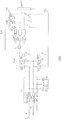
- the structure of the DC charging device is more precisely visible on the figure 3 .
- the input filter FE of the charging device DC receives each of the supply phases ⁇ 1, ⁇ 2, ⁇ 3 at a connection to an inductive filter consisting of an inductance L1 connected in series with a resistor R, and of an inductor L2 connected in parallel with the branch comprising in series the inductance L1 and the resistor R.
- the output of each inductive filter of the input filter FE is connected in the input filter FE, to a capacitive filter constituted by the capacitors Differential C1, C2 and C3.
- the differential capacitors C1, C2, C3 each comprise a first end and a second end.
- the capacitors C1, C2 and C3 are star-connected at their first ends and each connected at their second ends to an output of one of the inductive filters corresponding to a supply phase ⁇ 1, ⁇ 2, or ⁇ 3.
- the three outputs of the inductive filters extend at the output of the input filter FE and are connected to the inputs of the rectifier stage RED.
- the supply network RES is a three-phase network, the three phase connections ⁇ 1, ⁇ 2, or ⁇ 3 at the input of the input filter FE are therefore each connected to a power supply phase of the RES supply network.
- the RES supply network is a single-phase network.
- only two phase connections ⁇ 1 and ⁇ 3 at the input of the input filter FE are connected to the supply network RES, one to the supply phase of the single-phase network and the other to the neutral phase. of the single-phase network.
- no current flows in the capacitor C2 and an arm of the rectifier stage RED to which the capacitor C2 is connected.
- Capacities C1 and C3 are then equivalent to a single capacitor connected between the supply phase and the neutral phase.
- the "low” and “high” switches of the RED rectifier stage are power transistors such as IGBTs (according to the English “Insulated Gate Bipolar Transistor”).
- the inductance L is an inductance of value similar to that of the stator windings to which the inductance L is connected by the neutral point of the traction motor.
- Each of these stator windings is also connected, at its end not connected to the neutral point of the motor, to an input of the undulator stage OND which is a midpoint of an arm connected via a diode, respectively D7, D8 or D9, to the positive terminal of the BATT battery via an REL relay.
- Each midpoint of one of the three arms of the OND inverter stage is also connected via a power switch, respectively I7, I8 or I9, to the negative terminal of the battery BATT, via an REL relay.
- a smoothing capacitor C is further connected in parallel to the terminals of the BATT battery, at the output of the OND inverter.
- an active discharge method according to the invention is represented in the form of an algorithm comprising steps E1 to E4.
- the method is implemented in the control means MC of the DC charging device.
- the relays REL are closed, and that the charging device DC obeys a switching request called "toggle" request sent by the charging terminal BC.
- Step E1 is the detection of a power failure of the network RES, for example by means of current sensors located at the level of the connections of the input filter FE to the supply phases of the network RES.
- the control means MC receive from these sensors current values close to zero for all the supply phases, then a mains power failure is detected.
- the next step E2 is the closing of the switches I1 to I6 of the rectifier stage RED by the control means MC.
- the RED rectifier stage then functions as a simple bridge of diodes.
- the next step E3 is the opening of the switches I7 to I9 of the ELE voltage booster stage.
- the control means MC communicate with a microcontroller of the ELE stage elevator.
- Steps E1 to E3 enable the capacitors C1 to C3 to partially discharge into the battery BATT, the battery voltage BATT eventually oppose this discharge, which results in the blocking of diodes D1, D2 D3 and D7, D8, D9.
- the switches I7 to I9 of the ELE voltage booster stage are maintained in opening at least until the diodes of the RED rectifier stage are blocked.
- This blocking is for example detected by a value of current flowing in the inductance L reaching the zero value, this value being raised to the control means MC by a current sensor at the output of the rectifier stage RED.
- this blocking of the diodes is not detected, the control means MC realizing in this case the next step E4 after a predetermined duration after the step E2, for example 0.5 milliseconds.
- the next step E4 is the switching of switches I7, I8 and I9 of the ELE voltage booster stage until the voltage level between two input points of the rectifier stage RED is below a threshold of predetermined voltage, for example 1 volt.
- a threshold of predetermined voltage for example 1 volt.
- the voltage between two input points of the rectifier stage RED is representative of the residual voltage across the differential capacitors C1, C2 and C3. The value of this voltage is given for example by one or more voltage sensors at the input of the rectifier stage RED, to the control means MC.
- the switching of the switches I7, I8 and I9 in this step E4 is performed by a control of the control means MC to the microcontroller of the step ELE stage, which performs a control of these switches by pulse width modulation in a duty cycle increasing from 0% (switches open over a period of modulation) to 100% (switches closed over a period of modulation) linearly.
- the evolution of this duty cycle follows a ramp with a calculation step at 10 kHz (kilohertz). This ramp is calibrated so as to ensure the absence of overcurrent because of the dynamics and the routing of a maximum current to the battery BATT.
- step E4 the progressivity of the duty cycle ratio of the switches of the ELE voltage booster stage makes it possible to completely discharge the differential capacitors C1, C2 and C3 without their energy being mainly dissipated as losses in the inductances downstream of the rectifier stage RED.
- the residual voltage across the set of capacitors C1 and C3 in series is therefore 500V at the time of step E1, and decreases in step E3 discharging the capacitances in the battery BATT by simply closing the switches of the device DC load. After about 0.3 milliseconds, a rise in the residual voltage due to the blocking of the diodes of the RED rectifier stage is observed. After about 5 milliseconds, the step E4 of progressive switching is triggered and makes it possible to reduce this residual voltage to a zero value.
- step E4 the programming of steps E1 to E4 in the control means MC is performed in less than 10 milliseconds, which is sufficient to secure the components of the charging device during a switchover performed at the request of the charging station.
- BC for vehicle identification VEH.
- step E4 this should be programmed from preferably in a time greater than 0.5 milliseconds and less than 99 milliseconds after opening the switches of the ELE voltage booster stage in step E3, in order to make the charging device DC compatible with the switching requests as defined by the SAE standard.
- the RED rectifier stage comprises switches
- the invention is feasible on a charging device comprising a simple diode bridge as a rectifier.
- step E2 is not performed.
- the charging device DC has a different topology.
- the charging device DC does not use the stator windings of the traction motor as energy buffers in the step-up stage, but other inductances.
- the inverter has a diode on each of its half-arms, a transistor being arranged in parallel with each diode.
- the battery relays are physically integrated in the traction battery.
Landscapes
- Engineering & Computer Science (AREA)
- Power Engineering (AREA)
- Transportation (AREA)
- Mechanical Engineering (AREA)
- Electric Propulsion And Braking For Vehicles (AREA)
- Charge And Discharge Circuits For Batteries Or The Like (AREA)
Claims (10)
- Verfahren zur aktiven Entladung mindestens eines Kondensators (C1, C2, C3) am Eingang einer Ladevorrichtung (DC) eines Elektro- oder Hybridfahrzeugs (VEH), die mit einem einphasigen oder dreiphasigen Versorgungsnetz (RES) verbunden werden kann, wobei die Vorrichtung (DC) den mindestens einen Kondensator (C1, C2, C3) am Eingang einer Spannungsgleichrichterstufe (RED) mit Dioden (D1, D2, D3, D4, D5, D6) aufweist, deren Ausgang mit dem Eingang einer Spannungsaufwärtswandlerstufe (ELE) verbunden ist, die Schalter (I7, I8, I9) aufweist, wobei eine Traktionsbatterie (BATT) am Ausgang der Spannungsaufwärtswandlerstufe (ELE) mittels Relais (REL) verbunden ist, wobei das Verfahren dadurch gekennzeichnet ist, dass es, wenn das Netz (RES) mit der Vorrichtung (DC) verbunden ist und wenn die Relais (REL) geschlossen sind, folgende Schritte aufweist:- Erfassung (E1) einer Stromunterbrechung des Netzes (RES),- Öffnungssteuerung (E3) der Schalter (I7, I8, I9) der Spannungsaufwärtswandlerstufe (ELE), wobei die Schalter (I7, I8, I9) mindestens bis zur Blockierung der Dioden (D1, D2, D3, D4, D5, D6) der Gleichrichterstufe (RED) offen gehalten werden,- Umschaltung (E4) der Schalter (I7, I8, I9) der Spannungsaufwärtswandlerstufe (ELE), bis der Spannungspegel des mindestens einen Kondensators (C1, C2, C3) unter einer vorbestimmten Spannungsschwelle liegt.
- Verfahren zur aktiven Entladung nach Anspruch 1, dadurch gekennzeichnet, dass im Schaltschritt (E4) die Umschaltung der Schalter (I7, I8, I9) der Spannungsaufwärtswandlerstufe (ELE) gemäß einem Tastverhältnis erfolgt, das sich in einer vorbestimmten Dauer von weniger als 0,5 ms von 0 % bis 100 % entwickelt.
- Verfahren zur aktiven Entladung nach Anspruch 2, wobei im Schaltschritt (E4) das Schalt-Tastverhältnis der Schalter (I7, I8, I9) der Spannungsaufwärtswandlerstufe (ELE) sich linear mit einer Rechenschrittfrequenz von 10 kHz entwickelt.
- Verfahren zur aktiven Entladung nach einem der Ansprüche 1 bis 3, wobei, wenn die Gleichrichterstufe (RED) Schalter (I1, I2, I3, I4, I5, I6) in Reihe mit den Dioden (D1, D2, D3, D4, D5, D6) aufweist, vor dem Schritt der Öffnungssteuerung (E3) der Schalter (I7, I8, I9) der Spannungsaufwärtswandlerstufe (ELE) ein Schritt des Schließens (E2) der Schalter (I1, I2, I3, I4, I5, I6) der Gleichrichterstufe (RED) liegt.
- Verfahren zur aktiven Entladung nach einem der Ansprüche 1 bis 4, wobei der Schaltschritt (E4) der Schalter (I7, I8, I9) in einer Zeitspanne von mehr als 0,5 Millisekunden und weniger als 99 Millisekunden nach der Öffnungssteuerung (E3) der Schalter (I7, I8, I9) der Spannungsaufwärtswandlerstufe (ELE) programmiert ist.
- System zur aktiven Entladung mindestens eines Kondensators (C1, C2, C3) am Eingang einer Ladevorrichtung (DC) eines Elektro- oder Hybridfahrzeugs (VEH), die mit einem einphasigen oder dreiphasigen Versorgungsnetz (RES) verbunden werden kann, wobei die Vorrichtung (DC) den mindestens einen Kondensator (C1, C2, C3) am Eingang einer Spannungsgleichrichterstufe (RED) mit Dioden (D1, D2, D3, D4, D5, D6) aufweist, deren Ausgang mit dem Eingang einer Spannungsaufwärtswandlerstufe (ELE) verbunden ist, die Schalter (I7, I8, I9) aufweist, wobei eine Traktionsbatterie (BATT) am Ausgang der Spannungsaufwärtswandlerstufe (ELE) mittels Relais (REL) verbunden ist, wobei das System dadurch gekennzeichnet ist, dass es aufweist:- Einrichtungen zur Erfassung einer Stromunterbrechung des Netzes (RES), wenn die Relais (REL) geschlossen sind, die Steuereinrichtungen des Systems aktivieren können,- wobei die Steuereinrichtungen die Öffnung der Schalter (I7, I8, I9) der Spannungsaufwärtswandlerstufe (ELE) steuern und die Schalter (I7, I8, I9) der Spannungsaufwärtswandlerstufe (ELE) mindestens bis zur Blockierung der Dioden (D1, D2, D3, D4, D5, D6) der Gleichrichterstufe (RED) offen halten können,- Schalteinrichtungen der Schalter (I7, I8, I9) der Spannungsaufwärtswandlerstufe (ELE), die die Schalter (I7, I8, I9) nach der Blockierung der Dioden (D1, D2, D3, D4, D5, D6) der Gleichrichterstufe (RED) umschalten können, bis der Spannungspegel des mindestens einen Kondensators (C1, C2, C3) unter einer vorbestimmten Spannungsschwelle liegt.
- System zur aktiven Entladung nach Anspruch 6, dadurch gekennzeichnet, dass die Schalteinrichtungen die Schalter (I7, I8, I9) der Spannungsaufwärtswandlerstufe (ELE) nach der Blockierung der Dioden (D1, D2, D3, D4, D5, D6) der Gleichrichterstufe (RED) gemäß einem Tastverhältnis umschalten können, das sich in einer vorbestimmten Dauer von weniger als 0,5 ms von 0 % bis 100 % entwickelt.
- System zur aktiven Entladung nach Anspruch 7, wobei die Schalteinrichtungen die Schalter (I7, I8, I9) der Spannungsaufwärtswandlerstufe (ELE) nach der Blockierung der Dioden (D1, D2, D3, D4, D5, D6) der Gleichrichterstufe (RED) gemäß einem Tastverhältnis umschalten können, das sich linear mit einer Rechenschrittfrequenz von 10 kHz entwickelt.
- System zur aktiven Entladung nach einem der Ansprüche 6 bis 8, wobei, wenn die Gleichrichterstufe (RED) Schalter (I1, I2, I3, 14, I5, I6) in Reihe mit den Dioden (D1, D2, D3, D4, D5, D6) aufweist, die Erfassungseinrichtungen Schließeinrichtungen der Schalter (I1, I2, I3, I4, I5, I6) der Gleichrichterstufe (RED) aktivieren können.
- System zur aktiven Entladung nach einem der Ansprüche 6 bis 9, das Aktivierungseinrichtungen der Schalteinrichtungen der Schalter (I7, I8, I9) in einer Zeitspanne von mehr als 0,5 Millisekunden und weniger als 99 Millisekunden nach einer Aktivierung der Steuereinrichtungen durch die Erfassungseinrichtungen aufweist.
Applications Claiming Priority (2)
| Application Number | Priority Date | Filing Date | Title |
|---|---|---|---|
| FR1650063A FR3046508B1 (fr) | 2016-01-06 | 2016-01-06 | Procede et systeme de decharge active des capacites d'entree d'un chargeur embarque de vehicule electrique ou hybride |
| PCT/FR2017/050009 WO2017118807A1 (fr) | 2016-01-06 | 2017-01-04 | Procédé et système de décharge active des capacités d'entrée d'un chargeur embarqué de véhicule électrique ou hybride |
Publications (2)
| Publication Number | Publication Date |
|---|---|
| EP3400148A1 EP3400148A1 (de) | 2018-11-14 |
| EP3400148B1 true EP3400148B1 (de) | 2019-12-04 |
Family
ID=55953195
Family Applications (1)
| Application Number | Title | Priority Date | Filing Date |
|---|---|---|---|
| EP17702421.3A Active EP3400148B1 (de) | 2016-01-06 | 2017-01-04 | Verfahren und system zur aktiven entladung der eingangskondensatoren in einer bordladevorrichtung für ein elektro- oder hybridfahrzeug |
Country Status (4)
| Country | Link |
|---|---|
| EP (1) | EP3400148B1 (de) |
| KR (1) | KR102559385B1 (de) |
| FR (1) | FR3046508B1 (de) |
| WO (1) | WO2017118807A1 (de) |
Family Cites Families (2)
| Publication number | Priority date | Publication date | Assignee | Title |
|---|---|---|---|---|
| FR2976738B1 (fr) * | 2011-06-14 | 2013-07-19 | Commissariat Energie Atomique | Systeme de batteries d'accumulateurs a supervision simplifiee |
| JP6007876B2 (ja) * | 2013-09-04 | 2016-10-12 | 株式会社デンソー | 給電車両及び給電システム |
-
2016
- 2016-01-06 FR FR1650063A patent/FR3046508B1/fr not_active Expired - Fee Related
-
2017
- 2017-01-04 EP EP17702421.3A patent/EP3400148B1/de active Active
- 2017-01-04 WO PCT/FR2017/050009 patent/WO2017118807A1/fr not_active Ceased
- 2017-01-04 KR KR1020187021386A patent/KR102559385B1/ko active Active
Non-Patent Citations (1)
| Title |
|---|
| None * |
Also Published As
| Publication number | Publication date |
|---|---|
| WO2017118807A1 (fr) | 2017-07-13 |
| KR20180101420A (ko) | 2018-09-12 |
| FR3046508A1 (fr) | 2017-07-07 |
| FR3046508B1 (fr) | 2017-12-29 |
| EP3400148A1 (de) | 2018-11-14 |
| KR102559385B1 (ko) | 2023-07-25 |
Similar Documents
| Publication | Publication Date | Title |
|---|---|---|
| EP3105845B1 (de) | Gleichspannungsversorgungssystem zur vorladung eines glättungskondensators vor der speisung einer last | |
| EP2532069B1 (de) | Ladungsausgleichssystem für batterien | |
| EP2732530B1 (de) | Schnelles mehrstufiges wiederaufladesystem | |
| EP2781001B1 (de) | Gleichspannungsquelle einschliesslich brennstoffzellen mit anpassungfähigem spannungspegel | |
| EP2707945B1 (de) | Verfahren zur steuerung einer elektrischen drehmaschine, steuersystem und elektrische drehmaschine dafür | |
| FR2943188A1 (fr) | Dispositif de charge rapide pour un vehicule electrique. | |
| EP3053247B1 (de) | System und verfahren zum laden einer traktionsbatterie mit begrenzung der stromaufnahme parasitärer kapazitäten | |
| EP2915244B1 (de) | Ladungsübertragungsverfahren und zugehörige elektrische vorrichtung | |
| FR2997583A1 (fr) | Systeme d'alimentation electrique a double stockeurs d'energie electrique d'un vehicule automobile ou hybride | |
| WO2015049427A1 (fr) | Procédé de décharge d'au moins une unité de stockage d'énergie électrique, notamment un condensateur, d'un circuit électrique | |
| FR3073690B1 (fr) | Procede de commande d'un redresseur de vienne triphase lorsqu'un interrupteur de puissance est defaillant. | |
| EP3400148B1 (de) | Verfahren und system zur aktiven entladung der eingangskondensatoren in einer bordladevorrichtung für ein elektro- oder hybridfahrzeug | |
| WO2019110297A1 (fr) | Convertisseur continu-continu avec pre-charge d'un premier reseau electrique a partir d'un deuxieme reseau electrique | |
| WO2012101375A2 (fr) | Dispositif et procede d'equilibrage de l'etat de charge d'une source d'energie a stockage electrochimique composee de plusieurs cellules de stockage d'energie | |
| EP4633991A1 (de) | Verfahren zur beendigung der ladung und diagnose von schaltern eines ladesystems für ein elektro- oder hybridfahrzeug | |
| EP3681756A1 (de) | Fahrzeuglader mit einem gleichstromwandler | |
| EP1772303A1 (de) | Verfahren und System zum Einschalten eines Versorgungsbus eines elektrischen Fahrzeugs, Datenträger und Fahrzeug zur Durchführung des Verfahrens | |
| FR3018244A1 (fr) | Vehicule automobile electrique ou hybride muni d'un convertisseur dc-dc pour la charge et la traction, et procede correspondant | |
| FR2977083A1 (fr) | Architecture de batterie avec transmission magnetique de puissance et equilibrage en tension | |
| FR3162324A1 (fr) | Procédé de recharge d’une batterie par une source de tension inférieure à celle de la batterie et véhicule correspondant | |
| FR2997582A1 (fr) | Systeme d'alimentation electrique a double stockeurs d'energie electrique d'un vehicule automobile ou hybride | |
| WO2025195989A1 (fr) | Procédé et système de charge en courant continu d'une batterie de véhicule électrique ou hybride, utilisant une capacité de précharge | |
| FR3166584A1 (fr) | Procédé de recharge d’un véhicule électrique avec une borne de recharge de tension maximale supérieure ou inférieure à une tension maximale d’une batterie du véhicule | |
| EP4406772A1 (de) | Schienenfahrzeug mit stromspeicherung | |
| WO2014202879A1 (fr) | Procédé de gestion d'une charge alimentée par un convertisseur lui-même alimenté par une batterie, et système correspondant |
Legal Events
| Date | Code | Title | Description |
|---|---|---|---|
| STAA | Information on the status of an ep patent application or granted ep patent |
Free format text: STATUS: UNKNOWN |
|
| STAA | Information on the status of an ep patent application or granted ep patent |
Free format text: STATUS: THE INTERNATIONAL PUBLICATION HAS BEEN MADE |
|
| PUAI | Public reference made under article 153(3) epc to a published international application that has entered the european phase |
Free format text: ORIGINAL CODE: 0009012 |
|
| STAA | Information on the status of an ep patent application or granted ep patent |
Free format text: STATUS: REQUEST FOR EXAMINATION WAS MADE |
|
| 17P | Request for examination filed |
Effective date: 20180615 |
|
| AK | Designated contracting states |
Kind code of ref document: A1 Designated state(s): AL AT BE BG CH CY CZ DE DK EE ES FI FR GB GR HR HU IE IS IT LI LT LU LV MC MK MT NL NO PL PT RO RS SE SI SK SM TR |
|
| AX | Request for extension of the european patent |
Extension state: BA ME |
|
| DAV | Request for validation of the european patent (deleted) | ||
| DAX | Request for extension of the european patent (deleted) | ||
| REG | Reference to a national code |
Ref country code: DE Ref legal event code: R079 Ref document number: 602017009371 Country of ref document: DE Free format text: PREVIOUS MAIN CLASS: B60L0011180000 Ipc: B60L0053000000 |
|
| RIC1 | Information provided on ipc code assigned before grant |
Ipc: B60L 53/00 20190101AFI20190503BHEP |
|
| GRAP | Despatch of communication of intention to grant a patent |
Free format text: ORIGINAL CODE: EPIDOSNIGR1 |
|
| STAA | Information on the status of an ep patent application or granted ep patent |
Free format text: STATUS: GRANT OF PATENT IS INTENDED |
|
| INTG | Intention to grant announced |
Effective date: 20190628 |
|
| GRAS | Grant fee paid |
Free format text: ORIGINAL CODE: EPIDOSNIGR3 |
|
| GRAA | (expected) grant |
Free format text: ORIGINAL CODE: 0009210 |
|
| STAA | Information on the status of an ep patent application or granted ep patent |
Free format text: STATUS: THE PATENT HAS BEEN GRANTED |
|
| AK | Designated contracting states |
Kind code of ref document: B1 Designated state(s): AL AT BE BG CH CY CZ DE DK EE ES FI FR GB GR HR HU IE IS IT LI LT LU LV MC MK MT NL NO PL PT RO RS SE SI SK SM TR |
|
| REG | Reference to a national code |
Ref country code: GB Ref legal event code: FG4D Free format text: NOT ENGLISH |
|
| REG | Reference to a national code |
Ref country code: CH Ref legal event code: EP |
|
| REG | Reference to a national code |
Ref country code: AT Ref legal event code: REF Ref document number: 1208970 Country of ref document: AT Kind code of ref document: T Effective date: 20191215 |
|
| REG | Reference to a national code |
Ref country code: DE Ref legal event code: R096 Ref document number: 602017009371 Country of ref document: DE |
|
| REG | Reference to a national code |
Ref country code: IE Ref legal event code: FG4D Free format text: LANGUAGE OF EP DOCUMENT: FRENCH |
|
| REG | Reference to a national code |
Ref country code: NL Ref legal event code: MP Effective date: 20191204 |
|
| REG | Reference to a national code |
Ref country code: LT Ref legal event code: MG4D |
|
| PG25 | Lapsed in a contracting state [announced via postgrant information from national office to epo] |
Ref country code: NO Free format text: LAPSE BECAUSE OF FAILURE TO SUBMIT A TRANSLATION OF THE DESCRIPTION OR TO PAY THE FEE WITHIN THE PRESCRIBED TIME-LIMIT Effective date: 20200304 Ref country code: LT Free format text: LAPSE BECAUSE OF FAILURE TO SUBMIT A TRANSLATION OF THE DESCRIPTION OR TO PAY THE FEE WITHIN THE PRESCRIBED TIME-LIMIT Effective date: 20191204 Ref country code: BG Free format text: LAPSE BECAUSE OF FAILURE TO SUBMIT A TRANSLATION OF THE DESCRIPTION OR TO PAY THE FEE WITHIN THE PRESCRIBED TIME-LIMIT Effective date: 20200304 Ref country code: GR Free format text: LAPSE BECAUSE OF FAILURE TO SUBMIT A TRANSLATION OF THE DESCRIPTION OR TO PAY THE FEE WITHIN THE PRESCRIBED TIME-LIMIT Effective date: 20200305 Ref country code: LV Free format text: LAPSE BECAUSE OF FAILURE TO SUBMIT A TRANSLATION OF THE DESCRIPTION OR TO PAY THE FEE WITHIN THE PRESCRIBED TIME-LIMIT Effective date: 20191204 Ref country code: SE Free format text: LAPSE BECAUSE OF FAILURE TO SUBMIT A TRANSLATION OF THE DESCRIPTION OR TO PAY THE FEE WITHIN THE PRESCRIBED TIME-LIMIT Effective date: 20191204 Ref country code: FI Free format text: LAPSE BECAUSE OF FAILURE TO SUBMIT A TRANSLATION OF THE DESCRIPTION OR TO PAY THE FEE WITHIN THE PRESCRIBED TIME-LIMIT Effective date: 20191204 |
|
| PG25 | Lapsed in a contracting state [announced via postgrant information from national office to epo] |
Ref country code: HR Free format text: LAPSE BECAUSE OF FAILURE TO SUBMIT A TRANSLATION OF THE DESCRIPTION OR TO PAY THE FEE WITHIN THE PRESCRIBED TIME-LIMIT Effective date: 20191204 Ref country code: RS Free format text: LAPSE BECAUSE OF FAILURE TO SUBMIT A TRANSLATION OF THE DESCRIPTION OR TO PAY THE FEE WITHIN THE PRESCRIBED TIME-LIMIT Effective date: 20191204 |
|
| PG25 | Lapsed in a contracting state [announced via postgrant information from national office to epo] |
Ref country code: AL Free format text: LAPSE BECAUSE OF FAILURE TO SUBMIT A TRANSLATION OF THE DESCRIPTION OR TO PAY THE FEE WITHIN THE PRESCRIBED TIME-LIMIT Effective date: 20191204 |
|
| PG25 | Lapsed in a contracting state [announced via postgrant information from national office to epo] |
Ref country code: PT Free format text: LAPSE BECAUSE OF FAILURE TO SUBMIT A TRANSLATION OF THE DESCRIPTION OR TO PAY THE FEE WITHIN THE PRESCRIBED TIME-LIMIT Effective date: 20200429 Ref country code: ES Free format text: LAPSE BECAUSE OF FAILURE TO SUBMIT A TRANSLATION OF THE DESCRIPTION OR TO PAY THE FEE WITHIN THE PRESCRIBED TIME-LIMIT Effective date: 20191204 Ref country code: NL Free format text: LAPSE BECAUSE OF FAILURE TO SUBMIT A TRANSLATION OF THE DESCRIPTION OR TO PAY THE FEE WITHIN THE PRESCRIBED TIME-LIMIT Effective date: 20191204 Ref country code: CZ Free format text: LAPSE BECAUSE OF FAILURE TO SUBMIT A TRANSLATION OF THE DESCRIPTION OR TO PAY THE FEE WITHIN THE PRESCRIBED TIME-LIMIT Effective date: 20191204 Ref country code: RO Free format text: LAPSE BECAUSE OF FAILURE TO SUBMIT A TRANSLATION OF THE DESCRIPTION OR TO PAY THE FEE WITHIN THE PRESCRIBED TIME-LIMIT Effective date: 20191204 Ref country code: EE Free format text: LAPSE BECAUSE OF FAILURE TO SUBMIT A TRANSLATION OF THE DESCRIPTION OR TO PAY THE FEE WITHIN THE PRESCRIBED TIME-LIMIT Effective date: 20191204 |
|
| PG25 | Lapsed in a contracting state [announced via postgrant information from national office to epo] |
Ref country code: SM Free format text: LAPSE BECAUSE OF FAILURE TO SUBMIT A TRANSLATION OF THE DESCRIPTION OR TO PAY THE FEE WITHIN THE PRESCRIBED TIME-LIMIT Effective date: 20191204 Ref country code: IS Free format text: LAPSE BECAUSE OF FAILURE TO SUBMIT A TRANSLATION OF THE DESCRIPTION OR TO PAY THE FEE WITHIN THE PRESCRIBED TIME-LIMIT Effective date: 20200404 Ref country code: SK Free format text: LAPSE BECAUSE OF FAILURE TO SUBMIT A TRANSLATION OF THE DESCRIPTION OR TO PAY THE FEE WITHIN THE PRESCRIBED TIME-LIMIT Effective date: 20191204 |
|
| REG | Reference to a national code |
Ref country code: CH Ref legal event code: PL |
|
| REG | Reference to a national code |
Ref country code: DE Ref legal event code: R097 Ref document number: 602017009371 Country of ref document: DE |
|
| REG | Reference to a national code |
Ref country code: AT Ref legal event code: MK05 Ref document number: 1208970 Country of ref document: AT Kind code of ref document: T Effective date: 20191204 |
|
| PG25 | Lapsed in a contracting state [announced via postgrant information from national office to epo] |
Ref country code: MC Free format text: LAPSE BECAUSE OF FAILURE TO SUBMIT A TRANSLATION OF THE DESCRIPTION OR TO PAY THE FEE WITHIN THE PRESCRIBED TIME-LIMIT Effective date: 20191204 |
|
| PLBE | No opposition filed within time limit |
Free format text: ORIGINAL CODE: 0009261 |
|
| STAA | Information on the status of an ep patent application or granted ep patent |
Free format text: STATUS: NO OPPOSITION FILED WITHIN TIME LIMIT |
|
| REG | Reference to a national code |
Ref country code: BE Ref legal event code: MM Effective date: 20200131 |
|
| PG25 | Lapsed in a contracting state [announced via postgrant information from national office to epo] |
Ref country code: DK Free format text: LAPSE BECAUSE OF FAILURE TO SUBMIT A TRANSLATION OF THE DESCRIPTION OR TO PAY THE FEE WITHIN THE PRESCRIBED TIME-LIMIT Effective date: 20191204 Ref country code: LU Free format text: LAPSE BECAUSE OF NON-PAYMENT OF DUE FEES Effective date: 20200104 |
|
| 26N | No opposition filed |
Effective date: 20200907 |
|
| PG25 | Lapsed in a contracting state [announced via postgrant information from national office to epo] |
Ref country code: CH Free format text: LAPSE BECAUSE OF NON-PAYMENT OF DUE FEES Effective date: 20200131 Ref country code: AT Free format text: LAPSE BECAUSE OF FAILURE TO SUBMIT A TRANSLATION OF THE DESCRIPTION OR TO PAY THE FEE WITHIN THE PRESCRIBED TIME-LIMIT Effective date: 20191204 Ref country code: BE Free format text: LAPSE BECAUSE OF NON-PAYMENT OF DUE FEES Effective date: 20200131 Ref country code: LI Free format text: LAPSE BECAUSE OF NON-PAYMENT OF DUE FEES Effective date: 20200131 Ref country code: PL Free format text: LAPSE BECAUSE OF FAILURE TO SUBMIT A TRANSLATION OF THE DESCRIPTION OR TO PAY THE FEE WITHIN THE PRESCRIBED TIME-LIMIT Effective date: 20191204 Ref country code: SI Free format text: LAPSE BECAUSE OF FAILURE TO SUBMIT A TRANSLATION OF THE DESCRIPTION OR TO PAY THE FEE WITHIN THE PRESCRIBED TIME-LIMIT Effective date: 20191204 |
|
| PG25 | Lapsed in a contracting state [announced via postgrant information from national office to epo] |
Ref country code: IT Free format text: LAPSE BECAUSE OF FAILURE TO SUBMIT A TRANSLATION OF THE DESCRIPTION OR TO PAY THE FEE WITHIN THE PRESCRIBED TIME-LIMIT Effective date: 20191204 Ref country code: IE Free format text: LAPSE BECAUSE OF NON-PAYMENT OF DUE FEES Effective date: 20200104 |
|
| PG25 | Lapsed in a contracting state [announced via postgrant information from national office to epo] |
Ref country code: TR Free format text: LAPSE BECAUSE OF FAILURE TO SUBMIT A TRANSLATION OF THE DESCRIPTION OR TO PAY THE FEE WITHIN THE PRESCRIBED TIME-LIMIT Effective date: 20191204 Ref country code: MT Free format text: LAPSE BECAUSE OF FAILURE TO SUBMIT A TRANSLATION OF THE DESCRIPTION OR TO PAY THE FEE WITHIN THE PRESCRIBED TIME-LIMIT Effective date: 20191204 Ref country code: CY Free format text: LAPSE BECAUSE OF FAILURE TO SUBMIT A TRANSLATION OF THE DESCRIPTION OR TO PAY THE FEE WITHIN THE PRESCRIBED TIME-LIMIT Effective date: 20191204 |
|
| PG25 | Lapsed in a contracting state [announced via postgrant information from national office to epo] |
Ref country code: MK Free format text: LAPSE BECAUSE OF FAILURE TO SUBMIT A TRANSLATION OF THE DESCRIPTION OR TO PAY THE FEE WITHIN THE PRESCRIBED TIME-LIMIT Effective date: 20191204 |
|
| P01 | Opt-out of the competence of the unified patent court (upc) registered |
Effective date: 20230608 |
|
| REG | Reference to a national code |
Ref country code: DE Ref legal event code: R081 Ref document number: 602017009371 Country of ref document: DE Owner name: AMPERE S.A.S., FR Free format text: FORMER OWNER: RENAULT S.A.S., BOULOGNE-BILLANCOURT, FR |
|
| REG | Reference to a national code |
Ref country code: GB Ref legal event code: 732E Free format text: REGISTERED BETWEEN 20250501 AND 20250507 |
|
| PGFP | Annual fee paid to national office [announced via postgrant information from national office to epo] |
Ref country code: GB Payment date: 20260123 Year of fee payment: 10 |
|
| PGFP | Annual fee paid to national office [announced via postgrant information from national office to epo] |
Ref country code: DE Payment date: 20260121 Year of fee payment: 10 |
|
| PGFP | Annual fee paid to national office [announced via postgrant information from national office to epo] |
Ref country code: FR Payment date: 20260123 Year of fee payment: 10 |