EP3400454B1 - Antennenanordnung, insbesondere zur magnetresonanzbildgebung, mit linearen elektromagnetischen resonatoren und mindestens einer entkopplungsvorrichtung - Google Patents
Antennenanordnung, insbesondere zur magnetresonanzbildgebung, mit linearen elektromagnetischen resonatoren und mindestens einer entkopplungsvorrichtung Download PDFInfo
- Publication number
- EP3400454B1 EP3400454B1 EP17700616.0A EP17700616A EP3400454B1 EP 3400454 B1 EP3400454 B1 EP 3400454B1 EP 17700616 A EP17700616 A EP 17700616A EP 3400454 B1 EP3400454 B1 EP 3400454B1
- Authority
- EP
- European Patent Office
- Prior art keywords
- resonators
- antenna array
- array according
- loop
- linear
- Prior art date
- Legal status (The legal status is an assumption and is not a legal conclusion. Google has not performed a legal analysis and makes no representation as to the accuracy of the status listed.)
- Active
Links
Images






Classifications
-
- G—PHYSICS
- G01—MEASURING; TESTING
- G01R—MEASURING ELECTRIC VARIABLES; MEASURING MAGNETIC VARIABLES
- G01R33/00—Arrangements or instruments for measuring magnetic variables
- G01R33/20—Arrangements or instruments for measuring magnetic variables involving magnetic resonance
- G01R33/28—Details of apparatus provided for in groups G01R33/44 - G01R33/64
- G01R33/32—Excitation or detection systems, e.g. using radio frequency signals
- G01R33/36—Electrical details, e.g. matching or coupling of the coil to the receiver
- G01R33/3642—Mutual coupling or decoupling of multiple coils, e.g. decoupling of a receive coil from a transmission coil, or intentional coupling of RF coils, e.g. for RF magnetic field amplification
- G01R33/365—Decoupling of multiple RF coils wherein the multiple RF coils have the same function in MR, e.g. decoupling of a receive coil from another receive coil in a receive coil array, decoupling of a transmission coil from another transmission coil in a transmission coil array
-
- G—PHYSICS
- G01—MEASURING; TESTING
- G01R—MEASURING ELECTRIC VARIABLES; MEASURING MAGNETIC VARIABLES
- G01R33/00—Arrangements or instruments for measuring magnetic variables
- G01R33/20—Arrangements or instruments for measuring magnetic variables involving magnetic resonance
- G01R33/28—Details of apparatus provided for in groups G01R33/44 - G01R33/64
- G01R33/32—Excitation or detection systems, e.g. using radio frequency signals
- G01R33/34—Constructional details, e.g. resonators, specially adapted to MR
-
- G—PHYSICS
- G01—MEASURING; TESTING
- G01R—MEASURING ELECTRIC VARIABLES; MEASURING MAGNETIC VARIABLES
- G01R33/00—Arrangements or instruments for measuring magnetic variables
- G01R33/20—Arrangements or instruments for measuring magnetic variables involving magnetic resonance
- G01R33/28—Details of apparatus provided for in groups G01R33/44 - G01R33/64
- G01R33/32—Excitation or detection systems, e.g. using radio frequency signals
- G01R33/34—Constructional details, e.g. resonators, specially adapted to MR
- G01R33/34046—Volume type coils, e.g. bird-cage coils; Quadrature bird-cage coils; Circularly polarised coils
-
- H—ELECTRICITY
- H01—ELECTRIC ELEMENTS
- H01Q—ANTENNAS, i.e. RADIO AERIALS
- H01Q1/00—Details of, or arrangements associated with, antennas
- H01Q1/52—Means for reducing coupling between antennas; Means for reducing coupling between an antenna and another structure
- H01Q1/521—Means for reducing coupling between antennas; Means for reducing coupling between an antenna and another structure reducing the coupling between adjacent antennas
-
- H—ELECTRICITY
- H01—ELECTRIC ELEMENTS
- H01Q—ANTENNAS, i.e. RADIO AERIALS
- H01Q15/00—Devices for reflection, refraction, diffraction or polarisation of waves radiated from an antenna, e.g. quasi-optical devices
- H01Q15/0006—Devices acting selectively as reflecting surface, as diffracting or as refracting device, e.g. frequency filtering or angular spatial filtering devices
- H01Q15/0086—Devices acting selectively as reflecting surface, as diffracting or as refracting device, e.g. frequency filtering or angular spatial filtering devices said selective devices having materials with a synthesized negative refractive index, e.g. metamaterials or left-handed materials
-
- H—ELECTRICITY
- H01—ELECTRIC ELEMENTS
- H01Q—ANTENNAS, i.e. RADIO AERIALS
- H01Q9/00—Electrically-short antennas having dimensions not more than twice the operating wavelength and consisting of conductive active radiating elements
- H01Q9/04—Resonant antennas
- H01Q9/30—Resonant antennas with feed to end of elongated active element, e.g. unipole
Definitions
- An array antenna includes a plurality of electromagnetic resonators.
- the invention applies to the production of high frequency antennas (in English “RF coil”) with multiple channels and to their use in Magnetic Resonance Imaging devices (MRI, or MRI from English). "Magnetic Resonance Imaging" for humans or animals. More particularly still, it applies to the production of high frequency antennas for high field MRI, that is to say using a static magnetic field B 0 of intensity greater than or equal to 3 T (teslas) .
- the invention is however not limited to this single application.
- an antenna In Magnetic Resonance Imaging, an antenna is used in transmission to generate a radiofrequency field having a magnetic component capable of exciting the spins of atomic nuclei, in particular those of hydrogen (for the so-called proton MRI) within of a sample placed in the antenna.
- a radiofrequency field having a magnetic component capable of exciting the spins of atomic nuclei, in particular those of hydrogen (for the so-called proton MRI) within of a sample placed in the antenna.
- the static magnetic field called B 0 in which the sample is bathed, determines the frequency of the signal which is proportional to it. Thus, it goes from 64 MHz to 128 MHz for a field B 0 , of 1.5 and 3 teslas respectively.
- an antenna is generally composed of several resonators networked in order to obtain, on the one hand, a uniform excitation at through the parallel transmission process and, on the other hand, a better sensitivity in reception which improves the quality of the image.
- These resonators transmit and receive radio frequency signals.
- the operation of high-field MRI antennas is characterized by an inhomogeneity of the radiofrequency magnetic fields emitted or perceived by a single resonator: B 1 + in emission and B 1 - in reception.
- the amount B 1 + corresponds to the circular polarization of the magnetic field rotating in the same direction as the nuclear spins used for imaging.
- the quantity B 1 - is the polarization which turns in opposite direction and which characterizes the sensitivity in reception.
- the inhomogeneity of magnetic fields is inherent in the equations of electromagnetism. It increases with the frequency of the signal and therefore with the magnetic field B 0 .
- the inhomogeneity of B 1 + is reflected on an image by the appearance of areas of shadow or artificial contrast, difficult to interpret.
- a network antenna formed by a plurality of resonators must be used, to standardize either directly B 1 + , or the tilt angle. This compensation will be all the more effective the higher the number of resonators in a network antenna.
- a greater number of resonators will provide a more uniform overall reception profile with an increase in the signal to noise ratio.
- This increase could be used to increase the resolution of the image or to decrease the acquisition time by using an acceleration method which uses the differential sensitivity between resonators due to their construction or distribution around the sample. .
- improving the capacity and performance of a network antenna must go through an increase in the number of resonators.
- this approach is only effective when the size of each resonator is kept; in fact, the coupling between the resonators and the nuclear spins takes place in the near field, and a reduction in the size of the resonators would lead to a reduction in the depth of penetration of the high frequency field. Consequently, the increase in the number of resonators necessarily leads to a reduction in the distance between neighboring resonators which leads to an increase in mutual coupling.
- Document [1] applies the theory of electrical circuits to the study of coupling between resonators. It proposes to decouple the resonators by interconnecting them by means of a reactive circuit with discrete elements. This solution presupposes a precise knowledge of the characteristics of the resonators and their coupling coefficients, which is difficult - particularly in MRI where the presence of the sample unpredictably modifies these characteristics. In addition, the discrete reactive elements are difficult to use at high frequency, introduce significant losses and can hardly withstand the high voltages used in MRI with parallel transmission.
- linear resonators in English "stripline”, see for example reference [13]
- loop or circular resonators in English "loop”
- the mutual coupling is weaker between linear resonators for a given number in a given space, compared to loop resonators.
- the use of linear resonators is preferred in high-field MRI applications.
- [6] describes an antenna for high field MRI, in particular for acquiring images of the head, comprising a plurality of linear resonators arranged in a circle, so as to form a hollow cylinder.
- Another approach to decouple two electromagnetic resonators consists in separating them by a periodic passive structure built according to the principle of metamaterials. This structure is arranged so that once illuminated by an electromagnetic wave, it generates a magnetic field orthogonal to the direction of propagation of the wave identifiable by the Poynting vector; for this reason, the structure is generally called "magnetic conductor (or wall)".
- Publication [5] describes the application of such a metamaterial to the decoupling of two linear resonators of the 2.6 GHz monopoly type; publications [7], [8], international application [9] and European patent [10] relate to its application to loop-type resonators for MRI.
- Metamaterials have the disadvantage of introducing high losses; moreover, their structure is periodic, which limits the possibilities of optimizing the decoupling efficiency during use.
- the design of a decoupling device based on metamaterials requires numerical simulations which are very complex, since such a device necessarily includes a large number of objects (elementary resonators) of small size. We then come up against problems of RAM capacity and computing time.
- Documents [11] and [12] describe array antennas for MRI comprising two coplanar loop resonators separated by a spacing, and a decoupling resonator - also of the loop type - arranged in this spacing with an orientation perpendicular to that of the two. coplanar resonators, and therefore to the plane containing these.
- the metamaterials proposed by [5] and [7] - [10] consist of very small loop resonators lying in planes parallel to that which contains the resonators to be decoupled. This decoupling technique, proposed for loop resonators, has proved unsuitable for linear resonators, as will be discussed later with reference to the figure 14 .
- a network antenna according to claim 1 comprises a plurality of linear type electromagnetic resonators having longitudinal axes oriented parallel to each other and not arranged on a common axis, and at least one decoupling device arranged between two said adjacent linear electromagnetic resonators.
- the decoupling device comprises a plurality of decoupling resonators of the loop type, and more specifically open loop ("open loop" in English), that is to say comprising a loop interrupted by a capacitive element.
- the open loop type electromagnetic resonators are tuned to a frequency situated in the pass band of the two said adjacent linear type electromagnetic resonators, and electrically isolated from their environment.
- Each said open loop electromagnetic resonator having a characteristic dimension of the same order of magnitude as the length of the two said linear resonators.
- These decoupling resonators are arranged in a plurality of planes, not necessarily parallel to each other and substantially perpendicular, or in any case not parallel, to the plane containing two adjacent linear resonators (or, more exactly, their longitudinal axes) - and therefore to the vector of Poynting of the electromagnetic wave radiated by each of the two linear resonators to be decoupled.
- the mutual coupling is generally the result of the circulation of the magnetic field created by the excitation of the first, around the second; this circulation taking place on closed contours including the second resonator.
- the passage of an electric current 1 in the first resonator induces a current I 'such that
- the ratio I '/ I determines the strength of the mutual coupling.
- a decoupling device When a decoupling device according to the invention is placed in the electromagnetic field radiated by the first resonator, it in turn creates, still under Lenz's law, a magnetic field whose circulation over closed contours including the second resonator generates a current I "in the latter of opposite direction to the.
- the ideal decoupling is obtained when the algebraic sum of the current I" and I 'is zero. This condition requires a certain distribution in space of the magnetic fields associated both with the resonators to be decoupled and with the decoupling device itself.
- the implementation of a plurality of resonators, arranged in separate planes, in the decoupling device, makes it possible to synthesize a particular distribution of the magnetic field in order to modulate the amplitude of the current I ". This modulation makes it possible to optimize experimentally and easily decoupling during the development of the network antenna.
- a decoupling device 1 consists of the grouping of identical patterns 2.
- Each pattern, of planar shape, comprises a plurality of decoupling resonators 3, of the open loop type, the number of which in each of the two directions of the plane will be optimized according to the configuration of the resonators to be decoupled.
- the Figures 1a to 1c show patterns 2 including 1 ( fig. 1a ), 2 ( fig. 1b ), 3 ( fig. 1 C ), 4 ( fig. 1d ) and 6 (( fig. 1st ) decoupling resonators each.
- decoupling resonators 3 have no direct electrical connection between them or with any other element of the antenna.
- each resonator 3 is formed by a conductive track 6, for example made of copper, which closes on one or more discrete capacitors 7 and / or with distributed effects 8. Due to the absence of direct electrical connection, the discrete capacitors 7 are not subjected to high electrical voltages.
- the opposite track segments and constituting the distributed effect capacitors 8 can be trimmed to adjust the resonant frequency of the resonator 3. This frequency must be close to the operating frequency of the resonators to be decoupled. Its optimal value can be predetermined by numerical simulation or experimentally (heuristics): it must be within the bandwidth of the resonators to be decoupled.
- each decoupling resonator has a characteristic length (for example, its largest linear dimension - its largest dimension in the case of a rectangular geometry) of the same order of magnitude as the length of each of the linear resonators to be decoupled 4
- the characteristic length L D of each decoupling resonator is between 0.1 and 10 times, and preferably between 0.2 and 2 times, the length Lr of the resonators to be decoupled 4.
- the resonators of decoupling 3 have an elongated shape (for example rectangular, or elliptical) with a larger side (or a greater axis in the elliptical case) oriented parallel to the longitudinal axis L of the linear resonators to be decoupled 4.
- the decoupling resonators 3 can be produced according to the technique of printed circuits on a rigid support 9, typically the laminate Rogers 4350 of thickness 0.8 mm or flexible, typically a polyamide film of 50 microns.
- a pattern thus consists of a support 9 on which are arranged one or more resonators 3.
- a rigid interlayer 10 for example made of foam, must be added on either side of a pattern; a tab 10 can also be used to connect two patterns together ( figure 2 ).
- the materials constituting the support 9 and the interlayer 10 must have a minimum dielectric loss at the operating frequency.
- a network antenna according to the invention comprises at least two resonators to be decoupled 4, of the linear type.
- These resonators 4 are mutually parallel, that is to say that they have longitudinal axes L parallel to each other.
- they are arranged side by side, offset in a direction perpendicular to their common longitudinal direction (another possible configuration is illustrated on the figure 19 and will be discussed later). They are separated by a distance which is generally very small compared to the wavelength in the air ( ⁇ ) of the electromagnetic radiation that they emit. For example, this distance can be between 1% and 15% of ⁇ .
- Their length is generally close to ⁇ / 4, and typically between ⁇ / 8 and ⁇ and preferably between ⁇ / 8 and ⁇ / 2.
- these resonators 4 are arranged above a ground plane, or shield, 5.
- the decoupling device 1 is arranged between the two resonators 4 to be decoupled, on the same side of the ground plane 5 as these .
- the different patterns 2 of the decoupling device 1 are arranged in separate planes.
- a pattern 2 and its plane which will also be designated by the reference 2.
- These planes can be parallel to each other and perpendicular to the plane (reference pr on the figure 3b ) which contains the longitudinal axes L of the resonators 4.
- the planes of the patterns 2 are also perpendicular to the axis ( reference a1 on the figure 3a ) which unites the centers of the resonators to be decoupled, this axis also being parallel to the Poynting vector of the electromagnetic field emitted by each of the resonators 4.
- the planes 2 can be inclined relative to the plane pr, forming with the latter an angle which is generally between 10 ° and 170 ° and preferably between 45 ° and 135 °. In this case, it is not necessary that all the planes 2 are parallel to each other.
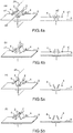
- the figures 3a to 3e illustrate various embodiments in which the planes of the patterns are mutually parallel and perpendicular to the plane pr and to the axis a1.
- figure 3e differs from that of the figure 3c only in that the two patterns in the middle are separated by a distance d1, less than that (d2) which separates them from the end patterns.
- the figure 4a shows a perspective view (left part of the figure) and in section (right part) of an embodiment in which the four patterns 2 are neither perpendicular to the axis a1 or to the plane pr, nor parallel to each other, but are open "book” with the more spaced sides facing up (opposite to the ground plane 5).
- the planes have turned around an axis a2 (represented only on the figure 4a ) parallel to the longitudinal axes L of the resonators 4 to be decoupled, and therefore parallel to the ground plane 5 and perpendicular to the plane pr and to the axis a1.
- the figure 4b shows the reverse configuration, in which the most spaced sides of the patterns 2 are oriented towards the ground plane 5.
- Figures 5a and 5b are different from those of Figures 4a and 4b in that the patterns are parallel two by two. They can also be linked, two by two, to rigid spacers 10 (cf. figure 2 ).
- the patterns 2 and the resonators to be decoupled 4 are arranged symmetrically with respect to a plane ps, perpendicular to the plane pr and to the axis a1.
- This ps plan is illustrated schematically on the only figures 3a , 4a and 5a .
- the position of the patterns 2 relative to the antennas can be easily adjusted, so as to optimize the decoupling effect.
- This adjustment can consist of a displacement and / or a rotation of the decoupling device 1 as a whole, but preferably at least certain patterns 2 can be moved, or rotated, independently of the others. This will be described later with reference to the figure 7 .
- shape and number of decoupling resonators 3, their relative arrangement, the positioning of the device 1 as a whole, etc. can be determined either by numerical calculation with commercial simulation codes, or by a heuristic approach.
- a proof of concept of the invention is provided for a simplified antenna operating in a 7 T MRI scanner (teslas) for the proton.
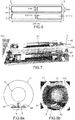
- a stack of three patterns 2 was used; the figure 6 shows the structure and dimensions of each of these patterns 2, comprising two decoupling resonators 3.
- the device 1 thus formed presents the following dimensions: 19 mm x 225 mm x 5.7 mm.
- the Larmor frequency of the proton is 297.2 MHz.
- These patterns thus dimensioned are used to decouple linear resonators 4, also called "dipoles" - see for example [6].
- the figure 7 shows the device 1 arranged between the two dipoles 41, 42.
- Grooved supports 100 at the ends of the device 1 keep the patterns in place 2.
- a pattern 2 can also be slid along the grooves so as to adjust its vertical position (direction "v") and therefore its distance from the ground plane 5.
- This set forms a simplified antenna; a real MRI array antenna for the human head generally comprises at least 8 dipoles surrounding the cavity 110.
- the curves of the figure 9 show the reflection coefficients (module of parameter S 11 of the distribution matrix - “scattering matrix ”in English) of each dipole placed alone in the armored shell 11, without its neighbor, as a function of the frequency f.
- the curve R41 0 in dotted line corresponds to the dipole 41, the curve R42 0 in continuous line to the dipole 42.
- the dipoles being nominally identical, and isolated, the two curves are very close
- the dipoles 41 and 42 are very well adapted in impedance, the reflection coefficients are at -29 dB and -34 dB for each of the dipoles.
- the reflection coefficients which were around -30 dB in the case dipoles taken in isolation pass to a value around -8 dB at the Larmor frequency ( figure 10 , curves R41 1 , R42 1 ).
- that is to say the transmission (curve T 1 ) between the two dipoles amounts to -5 dB, which means that more than a quarter of the power available in transmission on one of the dipoles is lost in the dissipative charge of the circulator to which each dipole is connected.
- the strong coupling between the two dipoles 41, 42 reveals two resonances around the Larmor frequency.
- a passive circuit composed of capacitors and inductors allows each dipole 41, 42 to be adjusted again to minimize the power reflected at the Larmor frequency.
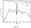
- the coupling between the radiating elements remains very high, effectively the transmission coefficient is -7 dB ( figure 11 , curves R41 1 , R41 2 , T 2 ).
- the addition of the decoupling device 1 makes it possible to act simultaneously on the reflection and transmission coefficients.
- of each dipole 41, 42 is only very slightly modified compared to the adjustment made when taken in isolation and the transmission coefficient
- the figure 13 shows the tilt angles ⁇ of the proton spins at the center of the phantom in the plane perpendicular to the largest dimension of the decoupling device in the 3 relevant configurations: dipoles taken in isolation ((a) and (d)), dipoles side by side side without decoupling device 1 ((b) and (e)), dipoles side by side with decoupling device 1 ((c) and (f)).
- the striated areas correspond to small tilt angles where the measurement artifacts are greater.
- the comparison shows that the decoupling device 1 fulfills its role well, that is to say that the angles associated with the radiated field (c) and (f) are much closer to (a) and (d) while the angles (b) and (e) differ quite markedly.
- FIG. 1a Another illustration of the particular properties conferred by the optimal spatial arrangement of a plurality of patterns 2 has been obtained by considering a simpler pattern 2 comprising only a single decoupling resonator 3, as shown in the figure 1a .
- This resonator has the shape and dimensions indicated on the figure 6 except that the second resonator in mirror symmetry with respect to the first has been removed.
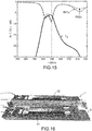
- the reflection and transmission curves obtained with a single pattern are shown on the figure 15 (curves R41 4 , R42 4 , T 4 ).
- the measurement was carried out in the configuration of the figure 8 , that is to say in the presence of the phantom 12 and inside the shell 11.
- the decoupling efficiency is very low with a single pattern.
- the curves R41 4 , R42 4 , T 4 are very similar to the curves R41 1 , R42 1 , T 1 of the figure 10 , obtained without the decoupling device 1.
- the decoupling resonators are strictly identical to one another.
- the linear resonators to be decoupled can be different from each other.
- the linear resonators to be decoupled are offset along their longitudinal axes L, which remain parallel; the decoupling device must then extend over the cumulative length of the two linear resonators to be decoupled.
- This configuration is shown on the figure 19 , where the axially offset resonators are identified by the references 401 and 402. It is noted that, in this case, the spatial orientation of the decoupling patterns is defined relative to the plane pr and not relative to the axis a1, which becomes less relevant.
- ground plane may not be parallel to the pr plane; it can even be replaced by a non-planar mass surface, for example generally concave with respect to the resonators 4 and obtained by the extrusion of a profile along the axis L.
Landscapes
- Physics & Mathematics (AREA)
- Condensed Matter Physics & Semiconductors (AREA)
- General Physics & Mathematics (AREA)
- Magnetic Resonance Imaging Apparatus (AREA)
Claims (15)
- Gruppenantenne, die eine Vielzahl von linearen elektromagnetischen Resonatoren (4) mit Längsachsen (L), die parallel zueinander orientiert und nicht auf einer gemeinsamen Achse angeordnet sind, und mindestens eine Entkopplungsvorrichtung (1) umfasst, die zwischen zwei benachbarten linearen elektromagnetischen Resonatoren angeordnet ist, wobei die Entkopplungsvorrichtung eine Vielzahl von elektromagnetischen Resonatoren des Typs mit offener Schleife (3) umfasst, abgestimmt auf eine Frequenz in der Bandbreite der zwei benachbarten linearen elektromagnetischen Resonatoren und elektrisch von ihrer Umgebung isoliert, wobei jeder elektromagnetische Resonator mit offener Schleife eine charakteristische Abmessung derselben Größenordnung hat wie die Länge der beiden benachbarten linearen Resonatoren, dadurch gekennzeichnet, dass die Vielzahl von elektromagnetischen Resonatoren des Typs mit offener Schleife in einer Vielzahl von jeweiligen Ebenen (2), die nicht parallel zu einer Ebene (pr) angeordnet sind, die die Längsachsen der beiden benachbarten linearen elektromagnetischen Resonatoren enthält.
- Gruppenantenne nach Anspruch 1, bei der die Ebenen, auf denen die elektromagnetischen Resonatoren des Typs mit offener Schleife angeordnet sind, einen Winkel zwischen 10° und 170°, und vorzugsweise zwischen 45° und 135°, mit der Ebene bilden, die die Längsachsen der beiden linearen elektromagnetischen Resonatoren enthält.
- Gruppenantenne nach einem der vorherigen Ansprüche, bei der die Entkopplungsvorrichtung eine Vielzahl von planaren Leiterplattenträgern (9) umfasst, auf denen jeweils 1 bis 6 der Resonatoren des Typs mit offener Schleife realisiert sind.
- Gruppenantenne nach einem der vorherigen Ansprüche, bei der die elektromagnetischen Resonatoren des Typs mit offener Schleife auf einer Anzahl von 2 bis 10, und vorzugsweise von 3 bis 6 Ebenen angeordnet sind.
- Gruppenantenne nach einem der vorherigen Ansprüche, bei der die Entkopplungsvorrichtung ein mechanisches Befestigungssystem (100) umfasst, das mindestens eine Modifikation der Geometrie der Vorrichtung zulässt, ausgewählt aus:• einer Bewegung von mindestens einem elektromagnetischen Resonator des Typs mit offener Schleife in einer Richtung (a1) senkrecht zu den Längsachsen (L) der beiden linearen elektromagnetischen Resonatoren, die in der Ebene (pr) liegen, die diese Achsen enthält;• einer Rotation von mindestens einem elektromagnetischen Resonator des Typs mit offener Schleife um eine Achse (a2) parallel zu den Längsachsen der beiden linearen elektromagnetischen Resonatoren; und• einer Bewegung von mindestens einem elektromagnetischen Resonator des Typs mit offener Schleife in seiner Ebene in einer Richtung (v) senkrecht zu den Längsachsen der beiden linearen elektromagnetischen Resonatoren.
- Gruppenantenne nach Anspruch 5, bei der das mechanische Befestigungssystem (100) so konfiguriert ist, dass es die Bewegung oder die Rotation von mindestens einem elektromagnetischen Resonator des Typs mit offener Schleife unabhängig von den anderen zulässt.
- Gruppenantenne nach einem der vorherigen Ansprüche, die auch eine Massefläche (5) umfasst, die global konkav in Bezug auf die beiden linearen elektromagnetischen Resonatoren ist und durch Extrusion eines Profils entlang ihrer Längsachsen erhalten wird.
- Gruppenantenne nach einem der vorherigen Ansprüche, bei der die Entkopplungsvorrichtung eine Symmetrie in Bezug auf eine Ebene (ps) senkrecht zu der Ebene (pr) aufweist, die die Längsachsen der beiden linearen elektromagnetischen Resonatoren enthält.
- Gruppenantenne nach einem der vorherigen Ansprüche, bei der die beiden linearen Resonatoren identisch sind.
- Gruppenantenne nach einem der vorherigen Ansprüche, bei der jeder elektromagnetische Resonator mit offener Schleife eine leitfähige Schleife umfasst, unterbrochen durch einen diskreten Kondensator (7) oder ein Element mit verteilter Kapazität (8).
- Gruppenantenne nach einem der vorherigen Ansprüche, bei der die beiden linearen elektromagnetischen Resonatoren Seite an Seite angeordnet sind, wobei eine Achse (a1), die ihre Mittelpunkte vereinigt, senkrecht zu ihren Längsachsen ist.
- Gruppenantenne nach einem der Ansprüche 1 bis 10, bei der die beiden linearen Resonatoren gleichzeitig in einer Richtung parallel zu ihren Längsachsen und einer Richtung senkrecht zu den Achsen versetzt sind.
- Gruppenantenne nach einem der vorherigen Ansprüche, die eine Vielzahl von linearen elektromagnetischen Resonatoren umfasst, die parallel zueinander und paarweise nebeneinander orientiert sind, wobei eine Entkopplungsvorrichtung zwischen jedem Paar von benachbarten linearen elektromagnetischen Resonatoren angeordnet ist.
- Gruppenantenne nach Anspruch 13, bei der die elektromagnetischen Resonatoren einen Hohlraum (110) umgeben, der das Einfügen eines Teils eines menschlichen oder tierischen Körpers zulässt.
- Kernspinresonanz-Bildgebungsgerät mit einer Gruppenantenne nach Anspruch 14.
Applications Claiming Priority (2)
| Application Number | Priority Date | Filing Date | Title |
|---|---|---|---|
| FR1650147A FR3046701B1 (fr) | 2016-01-08 | 2016-01-08 | Antenne reseau, en particulier pour imagerie par resonance magnetique nucleaire, comprenant des resonateurs electromagnetiques lineaires et au moins un dispositif de decouplage |
| PCT/EP2017/050179 WO2017118684A1 (fr) | 2016-01-08 | 2017-01-05 | Antenne reseau, en particulier pour imagerie par resonance magnetique nucleaire, comprenant des resonateurs electromagnetiques lineaires et au moins un dispositif de decouplage |
Publications (2)
| Publication Number | Publication Date |
|---|---|
| EP3400454A1 EP3400454A1 (de) | 2018-11-14 |
| EP3400454B1 true EP3400454B1 (de) | 2020-06-10 |
Family
ID=56137413
Family Applications (1)
| Application Number | Title | Priority Date | Filing Date |
|---|---|---|---|
| EP17700616.0A Active EP3400454B1 (de) | 2016-01-08 | 2017-01-05 | Antennenanordnung, insbesondere zur magnetresonanzbildgebung, mit linearen elektromagnetischen resonatoren und mindestens einer entkopplungsvorrichtung |
Country Status (4)
| Country | Link |
|---|---|
| US (1) | US10788549B2 (de) |
| EP (1) | EP3400454B1 (de) |
| FR (1) | FR3046701B1 (de) |
| WO (1) | WO2017118684A1 (de) |
Families Citing this family (4)
| Publication number | Priority date | Publication date | Assignee | Title |
|---|---|---|---|---|
| EP3679385B1 (de) * | 2017-09-07 | 2022-10-26 | Amherst College | Loop-gap-resonatoren für die spinresonanzspektroskopie |
| US11397228B2 (en) * | 2018-12-26 | 2022-07-26 | Khalifa University of Science and Technology | High-resolution UHF near-field imaging probe |
| CN114614263B (zh) * | 2022-03-28 | 2023-01-31 | 西安电子科技大学 | 一种双层金属表面的低剖面宽频带透射阵列天线 |
| CN115693152B (zh) * | 2022-12-30 | 2023-03-28 | 华南理工大学 | 天线去耦组件及天线 |
Family Cites Families (11)
| Publication number | Priority date | Publication date | Assignee | Title |
|---|---|---|---|---|
| JP3055136B2 (ja) * | 1998-03-16 | 2000-06-26 | 日本電気株式会社 | プリント回路基板 |
| GB2360094A (en) * | 2000-03-06 | 2001-09-12 | Marconi Caswell Ltd | RF screens for MRI |
| JP5179588B2 (ja) * | 2008-08-18 | 2013-04-10 | 株式会社日立メディコ | 高周波コイル及び磁気共鳴撮像装置 |
| WO2010045457A2 (en) | 2008-10-15 | 2010-04-22 | Regents Of The University Of Minnesota | Coil element decoupling for mri |
| FR2956214B1 (fr) * | 2010-02-09 | 2012-02-24 | Commissariat Energie Atomique | Resonateur lineaire d'une antenne haute frequence pour appareil d'imagerie par resonance magnetique nucleaire |
| US9885766B2 (en) | 2012-04-17 | 2018-02-06 | Transarray LLC | Magnetic-resonance transceiver-phased array that compensates for reactive and resistive components of mutual impedance between array elements and circuit and method thereof |
| US9627751B2 (en) * | 2012-11-30 | 2017-04-18 | The Chinese University Of Hong Kong | Device for decoupling antennas in compact antenna array and antenna array with the device |
| US20150369886A1 (en) * | 2013-01-11 | 2015-12-24 | Mri Innovations | System and method for decoupling magnetic resonance imaging radio frequency coils with a modular magnetic wall |
| US20150355297A1 (en) * | 2013-01-11 | 2015-12-10 | Ravi Menon | System and method for decoupling magentic resonance imaging radio frequency coils with a modular magnetic wall |
| KR101967241B1 (ko) * | 2013-01-16 | 2019-04-09 | 삼성전자주식회사 | 무선 주파수 코일 장치, 이를 채용한 자기 공명 장치, 및 무선 주파수 코일 장치의 작동방법 |
| US9397151B1 (en) * | 2013-08-30 | 2016-07-19 | Integrated Device Technology, Inc. | Packaged integrated circuits having high-Q inductors therein and methods of forming same |
-
2016
- 2016-01-08 FR FR1650147A patent/FR3046701B1/fr not_active Expired - Fee Related
-
2017
- 2017-01-05 EP EP17700616.0A patent/EP3400454B1/de active Active
- 2017-01-05 WO PCT/EP2017/050179 patent/WO2017118684A1/fr not_active Ceased
- 2017-01-05 US US16/068,646 patent/US10788549B2/en active Active
Non-Patent Citations (2)
| Title |
|---|
| GEORGET ELODIE ET AL: "Stacked magnetic resonators for MRI RF coils decoupling", JOURNAL OF MAGNETIC RESONANCE, ACADEMIC PRESS, ORLANDO, FL, US, vol. 275, 21 November 2016 (2016-11-21), pages 11 - 18, XP029893573, ISSN: 1090-7807, DOI: 10.1016/J.JMR.2016.11.012 * |
| P. J. FERRER ET AL: "Decorrelation of two closely spaced antennas with a metamaterial AMC surface", MICROWAVE AND OPTICAL TECHNOLOGY LETTERS, vol. 50, no. 5, 27 March 2008 (2008-03-27), US, pages 1414 - 1417, XP055614338, ISSN: 0895-2477, DOI: 10.1002/mop.23365 * |
Also Published As
| Publication number | Publication date |
|---|---|
| US10788549B2 (en) | 2020-09-29 |
| FR3046701B1 (fr) | 2018-03-23 |
| FR3046701A1 (fr) | 2017-07-14 |
| US20190018090A1 (en) | 2019-01-17 |
| WO2017118684A1 (fr) | 2017-07-13 |
| EP3400454A1 (de) | 2018-11-14 |
Similar Documents
| Publication | Publication Date | Title |
|---|---|---|
| EP2772771B1 (de) | Hochfrequenzantenne mit Mehrwegesystem, insbesondere für Kernspintomographie | |
| EP3400454B1 (de) | Antennenanordnung, insbesondere zur magnetresonanzbildgebung, mit linearen elektromagnetischen resonatoren und mindestens einer entkopplungsvorrichtung | |
| EP0575211B1 (de) | Strahlerelement einer Antenne mit breitbandigem Durchlassbereich und aus derartigen Elementen bestehende Gruppenantenne | |
| EP2534499B1 (de) | Linearresonator einer hr-antenne für ein kernmagnetresonanzbildgebungserät | |
| EP1145379B1 (de) | Antenne mit einer filtermaterialanordnung | |
| US20160149308A1 (en) | Modulation patterns for surface scattering antennas | |
| FR2691015A1 (fr) | Antenne-réseau de type micro-ruban à faible épaisseur mais à large bande passante. | |
| EP2921873B1 (de) | Sender-Empfänger mit Kreispolarisierungen für Magnetresonanzbildgebung | |
| Solomakha et al. | Evaluation of coaxial dipole antennas as transceiver elements of human head array for ultra‐high field MRI at 9.4 T | |
| WO1988008971A1 (fr) | Antenne electromagnetique et antenne d'excitation pour un appareil de resonance magnetique nucleaire munie d'une telle antenne electromagnetique | |
| EP3942649B1 (de) | Kompakte richtantenne, vorrichtung mit einer solchen antenne | |
| EP2734854B1 (de) | Verfahren zur herstellung eines kompakten steuermoduls für eine hochfrequenzantenne ein nmr-gerät | |
| Ilić et al. | Slotted‐waveguide array radio frequency coil for ultra‐high‐field magnetic resonance imaging | |
| WO2011104469A1 (fr) | Procede de realisation d'un module de pilotage d'une antenne haute frequence pour appareil d'imagerie par resonance magnetique nucleaire | |
| WO2015044554A1 (fr) | Systeme d'antenne radiofrequence fonde sur l'hybridation de mode pour dispositif de resonance magnetique nucleaire | |
| WO2005076028A1 (fr) | Cavite resonante de haute frequence pour la resonance magnetique nucleaire, utilisant des lignes de transmission radio-frequence. | |
| Crocker | Numerical and experimental evaluation of sinuous antennas for remote sensing applications | |
| EP4550578A1 (de) | Superdirektive schleifenantenne | |
| WO2017198914A1 (fr) | Procede de controle de la repartition du champ magnetique radiofrequence dans un systeme d'imagerie par resonance magnetique | |
| Gamez | Analysis and design of compact antennas in cavity based on metasurfaces for multiband GNSS applications | |
| Vineetha et al. | Leveraging butterfly meta material structures in a symmetric stub-loaded microstrip MIMO antenna for advanced biomedical and security applications | |
| Bizan | Ultra Wideband Stacked Rectangular Dielectric Resonator Antenna | |
| Denison et al. | A magnetic-conductor-like backplane for thin, conformal end-fire antennas |
Legal Events
| Date | Code | Title | Description |
|---|---|---|---|
| STAA | Information on the status of an ep patent application or granted ep patent |
Free format text: STATUS: UNKNOWN |
|
| STAA | Information on the status of an ep patent application or granted ep patent |
Free format text: STATUS: THE INTERNATIONAL PUBLICATION HAS BEEN MADE |
|
| PUAI | Public reference made under article 153(3) epc to a published international application that has entered the european phase |
Free format text: ORIGINAL CODE: 0009012 |
|
| STAA | Information on the status of an ep patent application or granted ep patent |
Free format text: STATUS: REQUEST FOR EXAMINATION WAS MADE |
|
| 17P | Request for examination filed |
Effective date: 20180704 |
|
| AK | Designated contracting states |
Kind code of ref document: A1 Designated state(s): AL AT BE BG CH CY CZ DE DK EE ES FI FR GB GR HR HU IE IS IT LI LT LU LV MC MK MT NL NO PL PT RO RS SE SI SK SM TR |
|
| AX | Request for extension of the european patent |
Extension state: BA ME |
|
| DAV | Request for validation of the european patent (deleted) | ||
| DAX | Request for extension of the european patent (deleted) | ||
| GRAP | Despatch of communication of intention to grant a patent |
Free format text: ORIGINAL CODE: EPIDOSNIGR1 |
|
| STAA | Information on the status of an ep patent application or granted ep patent |
Free format text: STATUS: GRANT OF PATENT IS INTENDED |
|
| RIC1 | Information provided on ipc code assigned before grant |
Ipc: G01R 33/36 20060101ALI20190823BHEP Ipc: G01R 33/34 20060101AFI20190823BHEP Ipc: H01Q 1/52 20060101ALI20190823BHEP |
|
| INTG | Intention to grant announced |
Effective date: 20190919 |
|
| GRAS | Grant fee paid |
Free format text: ORIGINAL CODE: EPIDOSNIGR3 |
|
| GRAJ | Information related to disapproval of communication of intention to grant by the applicant or resumption of examination proceedings by the epo deleted |
Free format text: ORIGINAL CODE: EPIDOSDIGR1 |
|
| GRAL | Information related to payment of fee for publishing/printing deleted |
Free format text: ORIGINAL CODE: EPIDOSDIGR3 |
|
| STAA | Information on the status of an ep patent application or granted ep patent |
Free format text: STATUS: REQUEST FOR EXAMINATION WAS MADE |
|
| INTC | Intention to grant announced (deleted) | ||
| GRAP | Despatch of communication of intention to grant a patent |
Free format text: ORIGINAL CODE: EPIDOSNIGR1 |
|
| STAA | Information on the status of an ep patent application or granted ep patent |
Free format text: STATUS: GRANT OF PATENT IS INTENDED |
|
| INTG | Intention to grant announced |
Effective date: 20200305 |
|
| GRAA | (expected) grant |
Free format text: ORIGINAL CODE: 0009210 |
|
| STAA | Information on the status of an ep patent application or granted ep patent |
Free format text: STATUS: THE PATENT HAS BEEN GRANTED |
|
| AK | Designated contracting states |
Kind code of ref document: B1 Designated state(s): AL AT BE BG CH CY CZ DE DK EE ES FI FR GB GR HR HU IE IS IT LI LT LU LV MC MK MT NL NO PL PT RO RS SE SI SK SM TR |
|
| REG | Reference to a national code |
Ref country code: GB Ref legal event code: FG4D Free format text: NOT ENGLISH |
|
| REG | Reference to a national code |
Ref country code: AT Ref legal event code: REF Ref document number: 1279612 Country of ref document: AT Kind code of ref document: T Effective date: 20200615 Ref country code: CH Ref legal event code: EP |
|
| REG | Reference to a national code |
Ref country code: DE Ref legal event code: R096 Ref document number: 602017017951 Country of ref document: DE |
|
| REG | Reference to a national code |
Ref country code: IE Ref legal event code: FG4D Free format text: LANGUAGE OF EP DOCUMENT: FRENCH |
|
| REG | Reference to a national code |
Ref country code: LT Ref legal event code: MG4D |
|
| PG25 | Lapsed in a contracting state [announced via postgrant information from national office to epo] |
Ref country code: FI Free format text: LAPSE BECAUSE OF FAILURE TO SUBMIT A TRANSLATION OF THE DESCRIPTION OR TO PAY THE FEE WITHIN THE PRESCRIBED TIME-LIMIT Effective date: 20200610 Ref country code: NO Free format text: LAPSE BECAUSE OF FAILURE TO SUBMIT A TRANSLATION OF THE DESCRIPTION OR TO PAY THE FEE WITHIN THE PRESCRIBED TIME-LIMIT Effective date: 20200910 Ref country code: LT Free format text: LAPSE BECAUSE OF FAILURE TO SUBMIT A TRANSLATION OF THE DESCRIPTION OR TO PAY THE FEE WITHIN THE PRESCRIBED TIME-LIMIT Effective date: 20200610 Ref country code: SE Free format text: LAPSE BECAUSE OF FAILURE TO SUBMIT A TRANSLATION OF THE DESCRIPTION OR TO PAY THE FEE WITHIN THE PRESCRIBED TIME-LIMIT Effective date: 20200610 |
|
| REG | Reference to a national code |
Ref country code: NL Ref legal event code: MP Effective date: 20200610 |
|
| PG25 | Lapsed in a contracting state [announced via postgrant information from national office to epo] |
Ref country code: BG Free format text: LAPSE BECAUSE OF FAILURE TO SUBMIT A TRANSLATION OF THE DESCRIPTION OR TO PAY THE FEE WITHIN THE PRESCRIBED TIME-LIMIT Effective date: 20200910 Ref country code: RS Free format text: LAPSE BECAUSE OF FAILURE TO SUBMIT A TRANSLATION OF THE DESCRIPTION OR TO PAY THE FEE WITHIN THE PRESCRIBED TIME-LIMIT Effective date: 20200610 Ref country code: HR Free format text: LAPSE BECAUSE OF FAILURE TO SUBMIT A TRANSLATION OF THE DESCRIPTION OR TO PAY THE FEE WITHIN THE PRESCRIBED TIME-LIMIT Effective date: 20200610 Ref country code: LV Free format text: LAPSE BECAUSE OF FAILURE TO SUBMIT A TRANSLATION OF THE DESCRIPTION OR TO PAY THE FEE WITHIN THE PRESCRIBED TIME-LIMIT Effective date: 20200610 |
|
| REG | Reference to a national code |
Ref country code: AT Ref legal event code: MK05 Ref document number: 1279612 Country of ref document: AT Kind code of ref document: T Effective date: 20200610 |
|
| PG25 | Lapsed in a contracting state [announced via postgrant information from national office to epo] |
Ref country code: NL Free format text: LAPSE BECAUSE OF FAILURE TO SUBMIT A TRANSLATION OF THE DESCRIPTION OR TO PAY THE FEE WITHIN THE PRESCRIBED TIME-LIMIT Effective date: 20200610 Ref country code: AL Free format text: LAPSE BECAUSE OF FAILURE TO SUBMIT A TRANSLATION OF THE DESCRIPTION OR TO PAY THE FEE WITHIN THE PRESCRIBED TIME-LIMIT Effective date: 20200610 |
|
| PG25 | Lapsed in a contracting state [announced via postgrant information from national office to epo] |
Ref country code: SM Free format text: LAPSE BECAUSE OF FAILURE TO SUBMIT A TRANSLATION OF THE DESCRIPTION OR TO PAY THE FEE WITHIN THE PRESCRIBED TIME-LIMIT Effective date: 20200610 Ref country code: IT Free format text: LAPSE BECAUSE OF FAILURE TO SUBMIT A TRANSLATION OF THE DESCRIPTION OR TO PAY THE FEE WITHIN THE PRESCRIBED TIME-LIMIT Effective date: 20200610 Ref country code: EE Free format text: LAPSE BECAUSE OF FAILURE TO SUBMIT A TRANSLATION OF THE DESCRIPTION OR TO PAY THE FEE WITHIN THE PRESCRIBED TIME-LIMIT Effective date: 20200610 Ref country code: AT Free format text: LAPSE BECAUSE OF FAILURE TO SUBMIT A TRANSLATION OF THE DESCRIPTION OR TO PAY THE FEE WITHIN THE PRESCRIBED TIME-LIMIT Effective date: 20200610 Ref country code: ES Free format text: LAPSE BECAUSE OF FAILURE TO SUBMIT A TRANSLATION OF THE DESCRIPTION OR TO PAY THE FEE WITHIN THE PRESCRIBED TIME-LIMIT Effective date: 20200610 Ref country code: PT Free format text: LAPSE BECAUSE OF FAILURE TO SUBMIT A TRANSLATION OF THE DESCRIPTION OR TO PAY THE FEE WITHIN THE PRESCRIBED TIME-LIMIT Effective date: 20201012 Ref country code: RO Free format text: LAPSE BECAUSE OF FAILURE TO SUBMIT A TRANSLATION OF THE DESCRIPTION OR TO PAY THE FEE WITHIN THE PRESCRIBED TIME-LIMIT Effective date: 20200610 Ref country code: CZ Free format text: LAPSE BECAUSE OF FAILURE TO SUBMIT A TRANSLATION OF THE DESCRIPTION OR TO PAY THE FEE WITHIN THE PRESCRIBED TIME-LIMIT Effective date: 20200610 |
|
| PG25 | Lapsed in a contracting state [announced via postgrant information from national office to epo] |
Ref country code: IS Free format text: LAPSE BECAUSE OF FAILURE TO SUBMIT A TRANSLATION OF THE DESCRIPTION OR TO PAY THE FEE WITHIN THE PRESCRIBED TIME-LIMIT Effective date: 20201010 Ref country code: PL Free format text: LAPSE BECAUSE OF FAILURE TO SUBMIT A TRANSLATION OF THE DESCRIPTION OR TO PAY THE FEE WITHIN THE PRESCRIBED TIME-LIMIT Effective date: 20200610 Ref country code: SK Free format text: LAPSE BECAUSE OF FAILURE TO SUBMIT A TRANSLATION OF THE DESCRIPTION OR TO PAY THE FEE WITHIN THE PRESCRIBED TIME-LIMIT Effective date: 20200610 |
|
| REG | Reference to a national code |
Ref country code: DE Ref legal event code: R097 Ref document number: 602017017951 Country of ref document: DE |
|
| PLBE | No opposition filed within time limit |
Free format text: ORIGINAL CODE: 0009261 |
|
| STAA | Information on the status of an ep patent application or granted ep patent |
Free format text: STATUS: NO OPPOSITION FILED WITHIN TIME LIMIT |
|
| PG25 | Lapsed in a contracting state [announced via postgrant information from national office to epo] |
Ref country code: DK Free format text: LAPSE BECAUSE OF FAILURE TO SUBMIT A TRANSLATION OF THE DESCRIPTION OR TO PAY THE FEE WITHIN THE PRESCRIBED TIME-LIMIT Effective date: 20200610 |
|
| 26N | No opposition filed |
Effective date: 20210311 |
|
| PG25 | Lapsed in a contracting state [announced via postgrant information from national office to epo] |
Ref country code: SI Free format text: LAPSE BECAUSE OF FAILURE TO SUBMIT A TRANSLATION OF THE DESCRIPTION OR TO PAY THE FEE WITHIN THE PRESCRIBED TIME-LIMIT Effective date: 20200610 |
|
| PG25 | Lapsed in a contracting state [announced via postgrant information from national office to epo] |
Ref country code: MC Free format text: LAPSE BECAUSE OF FAILURE TO SUBMIT A TRANSLATION OF THE DESCRIPTION OR TO PAY THE FEE WITHIN THE PRESCRIBED TIME-LIMIT Effective date: 20200610 |
|
| REG | Reference to a national code |
Ref country code: CH Ref legal event code: PL |
|
| PG25 | Lapsed in a contracting state [announced via postgrant information from national office to epo] |
Ref country code: LU Free format text: LAPSE BECAUSE OF NON-PAYMENT OF DUE FEES Effective date: 20210105 |
|
| REG | Reference to a national code |
Ref country code: BE Ref legal event code: MM Effective date: 20210131 |
|
| PG25 | Lapsed in a contracting state [announced via postgrant information from national office to epo] |
Ref country code: CH Free format text: LAPSE BECAUSE OF NON-PAYMENT OF DUE FEES Effective date: 20210131 Ref country code: LI Free format text: LAPSE BECAUSE OF NON-PAYMENT OF DUE FEES Effective date: 20210131 |
|
| PG25 | Lapsed in a contracting state [announced via postgrant information from national office to epo] |
Ref country code: IE Free format text: LAPSE BECAUSE OF NON-PAYMENT OF DUE FEES Effective date: 20210105 |
|
| PG25 | Lapsed in a contracting state [announced via postgrant information from national office to epo] |
Ref country code: BE Free format text: LAPSE BECAUSE OF NON-PAYMENT OF DUE FEES Effective date: 20210131 |
|
| PG25 | Lapsed in a contracting state [announced via postgrant information from national office to epo] |
Ref country code: CY Free format text: LAPSE BECAUSE OF FAILURE TO SUBMIT A TRANSLATION OF THE DESCRIPTION OR TO PAY THE FEE WITHIN THE PRESCRIBED TIME-LIMIT Effective date: 20200610 |
|
| PG25 | Lapsed in a contracting state [announced via postgrant information from national office to epo] |
Ref country code: HU Free format text: LAPSE BECAUSE OF FAILURE TO SUBMIT A TRANSLATION OF THE DESCRIPTION OR TO PAY THE FEE WITHIN THE PRESCRIBED TIME-LIMIT; INVALID AB INITIO Effective date: 20170105 Ref country code: GR Free format text: LAPSE BECAUSE OF FAILURE TO SUBMIT A TRANSLATION OF THE DESCRIPTION OR TO PAY THE FEE WITHIN THE PRESCRIBED TIME-LIMIT Effective date: 20200610 |
|
| PG25 | Lapsed in a contracting state [announced via postgrant information from national office to epo] |
Ref country code: MK Free format text: LAPSE BECAUSE OF FAILURE TO SUBMIT A TRANSLATION OF THE DESCRIPTION OR TO PAY THE FEE WITHIN THE PRESCRIBED TIME-LIMIT Effective date: 20200610 |
|
| PG25 | Lapsed in a contracting state [announced via postgrant information from national office to epo] |
Ref country code: MT Free format text: LAPSE BECAUSE OF FAILURE TO SUBMIT A TRANSLATION OF THE DESCRIPTION OR TO PAY THE FEE WITHIN THE PRESCRIBED TIME-LIMIT Effective date: 20200610 |
|
| PG25 | Lapsed in a contracting state [announced via postgrant information from national office to epo] |
Ref country code: TR Free format text: LAPSE BECAUSE OF FAILURE TO SUBMIT A TRANSLATION OF THE DESCRIPTION OR TO PAY THE FEE WITHIN THE PRESCRIBED TIME-LIMIT Effective date: 20200610 |
|
| PGFP | Annual fee paid to national office [announced via postgrant information from national office to epo] |
Ref country code: GB Payment date: 20260121 Year of fee payment: 10 |
|
| PGFP | Annual fee paid to national office [announced via postgrant information from national office to epo] |
Ref country code: DE Payment date: 20260120 Year of fee payment: 10 |
|
| PGFP | Annual fee paid to national office [announced via postgrant information from national office to epo] |
Ref country code: FR Payment date: 20260121 Year of fee payment: 10 |