EP3400511B1 - Bedienelement und damit ausgestattetes gerät - Google Patents
Bedienelement und damit ausgestattetes gerät Download PDFInfo
- Publication number
- EP3400511B1 EP3400511B1 EP17701755.5A EP17701755A EP3400511B1 EP 3400511 B1 EP3400511 B1 EP 3400511B1 EP 17701755 A EP17701755 A EP 17701755A EP 3400511 B1 EP3400511 B1 EP 3400511B1
- Authority
- EP
- European Patent Office
- Prior art keywords
- light
- domestic appliance
- appliance according
- light source
- opaque
- Prior art date
- Legal status (The legal status is an assumption and is not a legal conclusion. Google has not performed a legal analysis and makes no representation as to the accuracy of the status listed.)
- Active
Links
Images


Classifications
-
- H—ELECTRICITY
- H03—ELECTRONIC CIRCUITRY
- H03K—PULSE TECHNIQUE
- H03K17/00—Electronic switching or gating, i.e. not by contact-making and –breaking
- H03K17/94—Electronic switching or gating, i.e. not by contact-making and –breaking characterised by the way in which the control signals are generated
- H03K17/96—Touch switches
- H03K17/9625—Touch switches using a force resistance transducer
-
- G—PHYSICS
- G06—COMPUTING OR CALCULATING; COUNTING
- G06F—ELECTRIC DIGITAL DATA PROCESSING
- G06F3/00—Input arrangements for transferring data to be processed into a form capable of being handled by the computer; Output arrangements for transferring data from processing unit to output unit, e.g. interface arrangements
- G06F3/01—Input arrangements or combined input and output arrangements for interaction between user and computer
- G06F3/03—Arrangements for converting the position or the displacement of a member into a coded form
- G06F3/041—Digitisers, e.g. for touch screens or touch pads, characterised by the transducing means
- G06F3/0414—Digitisers, e.g. for touch screens or touch pads, characterised by the transducing means using force sensing means to determine a position
-
- G—PHYSICS
- G06—COMPUTING OR CALCULATING; COUNTING
- G06F—ELECTRIC DIGITAL DATA PROCESSING
- G06F3/00—Input arrangements for transferring data to be processed into a form capable of being handled by the computer; Output arrangements for transferring data from processing unit to output unit, e.g. interface arrangements
-
- F—MECHANICAL ENGINEERING; LIGHTING; HEATING; WEAPONS; BLASTING
- F21—LIGHTING
- F21V—FUNCTIONAL FEATURES OR DETAILS OF LIGHTING DEVICES OR SYSTEMS THEREOF; STRUCTURAL COMBINATIONS OF LIGHTING DEVICES WITH OTHER ARTICLES, NOT OTHERWISE PROVIDED FOR
- F21V11/00—Screens not covered by groups F21V1/00, F21V3/00, F21V7/00 or F21V9/00
- F21V11/02—Screens not covered by groups F21V1/00, F21V3/00, F21V7/00 or F21V9/00 using parallel laminae or strips, e.g. of Venetian-blind type
-
- F—MECHANICAL ENGINEERING; LIGHTING; HEATING; WEAPONS; BLASTING
- F21—LIGHTING
- F21V—FUNCTIONAL FEATURES OR DETAILS OF LIGHTING DEVICES OR SYSTEMS THEREOF; STRUCTURAL COMBINATIONS OF LIGHTING DEVICES WITH OTHER ARTICLES, NOT OTHERWISE PROVIDED FOR
- F21V23/00—Arrangement of electric circuit elements in or on lighting devices
- F21V23/04—Arrangement of electric circuit elements in or on lighting devices the elements being switches
- F21V23/0442—Arrangement of electric circuit elements in or on lighting devices the elements being switches activated by means of a sensor, e.g. motion or photodetectors
- F21V23/0485—Arrangement of electric circuit elements in or on lighting devices the elements being switches activated by means of a sensor, e.g. motion or photodetectors the sensor sensing the physical interaction between a user and certain areas located on the lighting device, e.g. a touch sensor
-
- F—MECHANICAL ENGINEERING; LIGHTING; HEATING; WEAPONS; BLASTING
- F21—LIGHTING
- F21V—FUNCTIONAL FEATURES OR DETAILS OF LIGHTING DEVICES OR SYSTEMS THEREOF; STRUCTURAL COMBINATIONS OF LIGHTING DEVICES WITH OTHER ARTICLES, NOT OTHERWISE PROVIDED FOR
- F21V31/00—Gas-tight or water-tight arrangements
- F21V31/005—Sealing arrangements therefor
-
- F—MECHANICAL ENGINEERING; LIGHTING; HEATING; WEAPONS; BLASTING
- F21—LIGHTING
- F21V—FUNCTIONAL FEATURES OR DETAILS OF LIGHTING DEVICES OR SYSTEMS THEREOF; STRUCTURAL COMBINATIONS OF LIGHTING DEVICES WITH OTHER ARTICLES, NOT OTHERWISE PROVIDED FOR
- F21V33/00—Structural combinations of lighting devices with other articles, not otherwise provided for
- F21V33/0004—Personal or domestic articles
- F21V33/0044—Household appliances, e.g. washing machines or vacuum cleaners
-
- F—MECHANICAL ENGINEERING; LIGHTING; HEATING; WEAPONS; BLASTING
- F24—HEATING; RANGES; VENTILATING
- F24D—DOMESTIC- OR SPACE-HEATING SYSTEMS, e.g. CENTRAL HEATING SYSTEMS; DOMESTIC HOT-WATER SUPPLY SYSTEMS; ELEMENTS OR COMPONENTS THEREFOR
- F24D19/00—Details
- F24D19/10—Arrangement or mounting of control or safety devices
- F24D19/1006—Arrangement or mounting of control or safety devices for water heating systems
- F24D19/1051—Arrangement or mounting of control or safety devices for water heating systems for domestic hot water
-
- G—PHYSICS
- G06—COMPUTING OR CALCULATING; COUNTING
- G06F—ELECTRIC DIGITAL DATA PROCESSING
- G06F3/00—Input arrangements for transferring data to be processed into a form capable of being handled by the computer; Output arrangements for transferring data from processing unit to output unit, e.g. interface arrangements
- G06F3/01—Input arrangements or combined input and output arrangements for interaction between user and computer
- G06F3/03—Arrangements for converting the position or the displacement of a member into a coded form
- G06F3/033—Pointing devices displaced or positioned by the user, e.g. mice, trackballs, pens or joysticks; Accessories therefor
- G06F3/0362—Pointing devices displaced or positioned by the user, e.g. mice, trackballs, pens or joysticks; Accessories therefor with detection of one-dimensional [1D] translations or rotations of an operating part of the device, e.g. scroll wheels, sliders, knobs, rollers or belts
-
- G—PHYSICS
- G09—EDUCATION; CRYPTOGRAPHY; DISPLAY; ADVERTISING; SEALS
- G09G—ARRANGEMENTS OR CIRCUITS FOR CONTROL OF INDICATING DEVICES USING STATIC MEANS TO PRESENT VARIABLE INFORMATION
- G09G3/00—Control arrangements or circuits, of interest only in connection with visual indicators other than cathode-ray tubes
- G09G3/02—Control arrangements or circuits, of interest only in connection with visual indicators other than cathode-ray tubes by tracing or scanning a light beam on a screen
-
- H—ELECTRICITY
- H03—ELECTRONIC CIRCUITRY
- H03K—PULSE TECHNIQUE
- H03K17/00—Electronic switching or gating, i.e. not by contact-making and –breaking
- H03K17/94—Electronic switching or gating, i.e. not by contact-making and –breaking characterised by the way in which the control signals are generated
- H03K17/96—Touch switches
-
- H—ELECTRICITY
- H03—ELECTRONIC CIRCUITRY
- H03K—PULSE TECHNIQUE
- H03K17/00—Electronic switching or gating, i.e. not by contact-making and –breaking
- H03K17/94—Electronic switching or gating, i.e. not by contact-making and –breaking characterised by the way in which the control signals are generated
- H03K17/965—Switches controlled by moving an element forming part of the switch
-
- H—ELECTRICITY
- H05—ELECTRIC TECHNIQUES NOT OTHERWISE PROVIDED FOR
- H05K—PRINTED CIRCUITS; CASINGS OR CONSTRUCTIONAL DETAILS OF ELECTRIC APPARATUS; MANUFACTURE OF ASSEMBLAGES OF ELECTRICAL COMPONENTS
- H05K5/00—Casings, cabinets or drawers for electric apparatus
-
- F—MECHANICAL ENGINEERING; LIGHTING; HEATING; WEAPONS; BLASTING
- F21—LIGHTING
- F21W—INDEXING SCHEME ASSOCIATED WITH SUBCLASSES F21K, F21L, F21S and F21V, RELATING TO USES OR APPLICATIONS OF LIGHTING DEVICES OR SYSTEMS
- F21W2131/00—Use or application of lighting devices or systems not provided for in codes F21W2102/00-F21W2121/00
- F21W2131/30—Lighting for domestic or personal use
-
- H—ELECTRICITY
- H03—ELECTRONIC CIRCUITRY
- H03K—PULSE TECHNIQUE
- H03K2217/00—Indexing scheme related to electronic switching or gating, i.e. not by contact-making or -breaking covered by H03K17/00
- H03K2217/94—Indexing scheme related to electronic switching or gating, i.e. not by contact-making or -breaking covered by H03K17/00 characterised by the way in which the control signal is generated
- H03K2217/96—Touch switches
- H03K2217/96015—Constructional details for touch switches
-
- H—ELECTRICITY
- H03—ELECTRONIC CIRCUITRY
- H03K—PULSE TECHNIQUE
- H03K2217/00—Indexing scheme related to electronic switching or gating, i.e. not by contact-making or -breaking covered by H03K17/00
- H03K2217/94—Indexing scheme related to electronic switching or gating, i.e. not by contact-making or -breaking covered by H03K17/00 characterised by the way in which the control signal is generated
- H03K2217/96—Touch switches
- H03K2217/96042—Touch switches with illumination
-
- H—ELECTRICITY
- H03—ELECTRONIC CIRCUITRY
- H03K—PULSE TECHNIQUE
- H03K2217/00—Indexing scheme related to electronic switching or gating, i.e. not by contact-making or -breaking covered by H03K17/00
- H03K2217/94—Indexing scheme related to electronic switching or gating, i.e. not by contact-making or -breaking covered by H03K17/00 characterised by the way in which the control signal is generated
- H03K2217/965—Switches controlled by moving an element forming part of the switch
- H03K2217/9653—Switches controlled by moving an element forming part of the switch with illumination
- H03K2217/9655—Switches controlled by moving an element forming part of the switch with illumination using a single or more light guides
Definitions
- the invention relates to an operating element and to a (domestic) appliance provided with such an operating element.
- An example of a domestic appliance in which the operating element is applicable is a hot water appliance or a thermostat therefor.
- High-end screens as for instance applied in smart phones and tablets, are touch-sensitive.
- a touch-sensitive screen can display a user interface adapted to the situation, wherein the screen itself can function as operating element.
- Applicant is a manufacturer of heating boilers, and there is also a desire for these products to be given a high-end look without having to integrate complex and vulnerable electronics. There is therefore a need for an operating element which combines robustness with a high-quality look.
- the European patent application EP-A2-1 640 837 discloses a system and method for controlling a network of water appliances for safer and more efficient operation, and is recognized as further prior art.
- the invention now has for its object to provide an operating element of the above described type, wherein said drawbacks do not occur, or at least do so to lesser extent.
- the control When the sensor detects operation of the operating element, the control will switch a light source on or off subject to a sensor signal coming from the sensor. This light is conducted to a side of the light conductor remote from the carrier by a light conductor arranged close to the light source.
- the screen comprises at least one opaque part and at least one translucent part, which together form a symbol. The light from the light source will then light up a symbol on the operating element in switched-on mode of the light source.
- a domestic appliance for instance a hot water appliance, requires a robust and reliable operation, which is provided by the operating element according to the invention.
- the light conductor comprises a force-transmitting component.
- the light conductor thus fulfils on the one hand the function of conducting and spreading light, and on the other hand fulfils the function of transmitting/transferring a pressure force.
- the domestic appliance can hereby be provided with a robust operation with pressure sensors which are desired for such appliances, while having the look and feel of a high-end touch pad.
- the light conductor has a height substantially corresponding to the height of an opaque side shield arranged adjacently thereof.
- the light conductor can hereby provide for a force transmission over the whole thickness of the opaque side shield.
- the pressure sensor is preferably arranged against the light conductor.
- the side shield must in principle provide an opaque side shield only on the side facing toward the light conductor, the side shield is more preferably a component which is substantially wholly opaque.
- a side of the light conductor remote from the carrier and a side of the side shield remote from the carrier are arranged substantially flush.
- a screen can hereby lie flat against the light conductor and the side shield, and a flat operating element is obtained.
- the substantially opaque side shield is provided at least between two light conductors.
- the operating element thus comprises at least two light conductors, wherein at least a substantially opaque side shield is provided between the light conductors.
- An operating element can thus be provided with at least two individually operable functions, such as a "plus” and "minus” mode for respectively raising or lowering a setting value. Because adjoining light conductors are separated from each other by opaque side shields, lateral scattering of light is prevented.
- Each symbol can hereby be provided with its own light source, and light is prevented from radiating from the one symbol to an adjacent other symbol.
- the operating element further comprises a transparent protective part which is arranged on the side of the screen remote from the carrier.
- This transparent protective part on one hand protects the underlying construction from outside influences. Contact between water or moisture and the electronics of the operating element can thus be prevented in a hot water appliance.
- the transparent protective part on the other hand shields the screen visually to some extent if the screen is not wholly transparent.
- the degree of transparency i.e. the degree of light transmission, can be chosen precisely in order to show a visually flat wall in a mode in which the light sources are switched off and to show a visually clear view of a symbol in the mode in which a light source is switched on.
- the colour of the protective part optionally in combination with the colour of the screen, determines the appearance of the operating element.
- the domestic appliance comprises at least two light conductors, wherein the protective part extends over at least two light conductors.
- the look and feel of a touch pad are in this way on the one hand achieved, wherein a plurality of functions actuable by pressure sensors are provided under one surface.
- a further advantage of the protective part extending over the light conductors is that it covers possible gaps. A reliable and moisture-resistant operating element can thus be provided, particularly for a domestic appliance such as a hot water appliance.
- the senor is arranged close to the light source.
- a compact construction in combination with a good force transmission is obtained if according to yet another preferred embodiment the light source is arranged adjacently of the light conductor.
- an optical sensor which detects the approach of a hand or a movement of the hand and sends this on to the control unit for processing, is for instance provided, according to a further preferred embodiment the sensor is arranged close to the light source. Such a configuration enables a compact construction of the operating element.
- the light conductor is substantially translucent, it can fulfil two functions.
- the light conductor on the one hand provides for conduction of the light, wherein the light conductor provides a diffuse spreading of the light.
- the light conductor can on the other hand transmit a pressure force to a touch-sensitive (pressure) sensor.
- the screen comprises a substantially opaque strip with openings.
- the openings of course allow light through, wherein the opaque strip and the light-transmitting openings together form a symbol which is visible when the light source is switched on.
- the screen comprises a printed film, wherein printed parts form an opaque part of the screen and wherein unprinted parts form a substantially translucent part of the screen.
- a printed film on the one hand makes it possible to form very detailed symbols.
- a gradient in light transmission can on the other hand also be obtained by means of the degree of printing.
- a printed film can moreover form a screen with a very limited thickness.
- the screen is integrated with the light conductor. It is thus possible to envisage the light conductor itself being substantially translucent, and itself being provided with opaque parts on the side remote from the light source. These opaque parts can for instance be a print applied directly to the light conductor, i.e. without interposing of a film as described in the foregoing.
- the opaque side shield is a substantially opaque strip comprising passages for receiving the light conductors therein. Because adjoining light conductors are mutually separated by opaque side shields, lateral scattering of light is prevented. Each symbol can thereby be provided with its own light source, and light is prevented from radiating from the one symbol to an adjacent other symbol.
- the opaque side shield is preferably embodied as an opaque strip with passages, wherein the shape of the passages corresponds to the shape of associated light conductors so that these conductors can be received in the passages substantially free of play.
- the opaque strip comprises a recess for receiving the light source therein.
- the light source can be received in the recess, wherein there is free passage at least to the light conductor. Because the recess shields the light source on the other sides, the light can only shine toward the light conductor.
- the symbol corresponds to the function of an appliance for which the operating element is used.
- a flame can thus be shown when the burner of the hot water appliance is switched on.
- the invention further relates to an appliance comprising an operating element according to the invention.
- the domestic appliance is preferably a hot water appliance and/or a thermostat associated therewith.
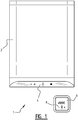
- an operating element 4, 8 is suitable for many different types of appliance
- a hot water appliance 2 and an associated thermostat 6 are shown in figure 1 as appliances 1.
- an operating element 4 Provided in hot water appliance 2 is an operating element 4, while thermostat 6 is equipped with an operating element 8 with a differing form.
- the construction of operating elements 4, 8 can be identical from a technical viewpoint.
- the following figures therefore show only the operating element 4 of hot water appliance 2 in two different preferred embodiments.
- a first preferred embodiment is the subject of figures 2 and 3
- a second preferred embodiment is shown in figures 4 and 5 .
- Figure 2 shows an exploded top view of an operating element 4 according to the first preferred embodiment.
- Operating element 4 comprises a carrier 12 which is embodied as a printed circuit board 14 in the shown embodiments.
- Printed circuit board 14 is provided with a sensor 16, which is a touch-sensitive sensor 18 such as a pressure sensor. When sensor 16 is operated, it sends a signal to control 20 which is configured to switch a light source 22 on or off subject to the sensor signal coming from sensor 16, 18.
- An opaque shielding strip 32 is arranged on carrier 12. This shielding strip 32 has openings 34 in which light conductors 28 and windows 30 can be arranged.
- printed circuit board 14 is likewise provided with conventional screens 24, and opaque shielding strip 32 has at the position of these screens 24 openings 34 in which a window 30 can be placed. Screens 24 can for instance show a current temperature value.
- Translucent light conductors 28 are physical elements which are arranged in openings 34 and provide two functionalities.
- Light conductor 28 on the one hand provides for the conducting and spreading of the light, wherein light conductor 28 provides a diffuse spreading of the light.
- Light conductor 28 can on the other hand transmit a pressure force to a pressure sensor 16, 18.
- a screen 40 comprising at least one substantially opaque part 42 and at least one substantially translucent part 44, which together form a symbol 46.
- screen 40 is embodied as a substantially opaque strip 42 with openings which form a translucent part.
- the openings form together with the opaque part a symbol 46 which lights up when control 20 switches on the light source 22 associated with this specific symbol 46.
- a substantially transparent protective part 56 which protects the underlying construction from outside influences, such as moisture or water, and which can be diffuse to limited extent in order to thus conceal symbols 46 and screen 40 from view when light sources 22 are switched off.
- Figure 3 shows an exploded side view of the operating element 4 shown in figure 2 , wherein a light conductor 28 is received in an opening 34 of opaque shielding strip 32.
- Opaque shielding strip 32 forms a side shield of the substantially translucent light conductors 28 and thus prevents light from a light source 22 being able to radiate via a light conductor 28 to an adjoining symbol 46. This prevents an adjoining symbol 46 from also lighting up to some extent.
- opaque shielding strip 32 is provided with recesses 36 in which light source 22 can be received.
- Recesses 36 form a free passage at least on the side facing toward light conductor 28, so that light emitted by light source 22 can enter light conductor 28 and can be conducted and spread therethrough. This results in a compact construction.
- light conductor 28 can be a substantially solid translucent component which transmits a limited bending of protective part 56 and screen 40 which is generated by a user to pressure sensor 18 in reliable manner.
- Light conductor 28 is arranged between pressure sensor 18 and a symbol 46 associated with the function of the relevant pressure sensor 18. A user who bends screen 40 to some extent at the position of symbol 46 using his or her finger thus compresses pressure sensor 18 via light conductor 28.
- Screen 40 with opaque part 42 and translucent part 44 is provided on the side of opaque shielding strip 32 remote from printed circuit board 14 ('top' in the figure).
- sensor 16 is a pressure sensor 18 which can be actuated by a force-transmitting light conductor 28 when a user generates a limited bending of protective part 56 and screen 40. Because light conductor 28 can display a symbol 46 of the function associated with the relevant sensor 18, an operating element 4 is created wherein a user can touch the symbol 46 which lights up him or herself for activating or deactivating the relevant function.
- Sensor 16 is a pressure sensor 18 which can be compressed when a user presses protective part 56 at the position of the relevant symbol 46. Protective part 56 will then bend to some extent and the pressure force will be transmitted via screen 40 and light conductor 28 to pressure-sensitive sensor 18. The sensor signal coming from sensor 16, 18 is then processed by control unit 20.
- the second preferred embodiment which is shown in figures 4 and 5 closely resembles the first embodiment of figures 2 and 3 .
- a printed film 48 is provided which has an opaque part 50 and a translucent part 52, and thus forms symbols 46.
- the advantage of a film 48 is that it enables symbols 46 to be detailed to an even higher degree, including application of a gradient in the light-permeability by a corresponding adjustment of the print on film 48.
- Film 48 can moreover function directly as screen 40, which makes it possible to realize an even more compact construction of the operating element.
Landscapes
- Engineering & Computer Science (AREA)
- General Engineering & Computer Science (AREA)
- Theoretical Computer Science (AREA)
- Physics & Mathematics (AREA)
- Human Computer Interaction (AREA)
- General Physics & Mathematics (AREA)
- Thermal Sciences (AREA)
- Chemical & Material Sciences (AREA)
- Combustion & Propulsion (AREA)
- Mechanical Engineering (AREA)
- Computer Hardware Design (AREA)
- Microelectronics & Electronic Packaging (AREA)
- Push-Button Switches (AREA)
- Switches That Are Operated By Magnetic Or Electric Fields (AREA)
- Input From Keyboards Or The Like (AREA)
- Illuminated Signs And Luminous Advertising (AREA)
- Selective Calling Equipment (AREA)
- Arrangement Of Elements, Cooling, Sealing, Or The Like Of Lighting Devices (AREA)
- Switches Operated By Changes In Physical Conditions (AREA)
Claims (15)
- Haushaltsgerät mit einem Bedienelement (4, 8), wobei das Bedienelement aufweist:- einen im Wesentlichen ebenen Träger (12), der mit mindestens einem berührungsempfindlichen Sensor (16, 18) versehen ist, welcher zur Erfassung einer Bedienung des Bedienelements ausgebildet ist, und zumindest eine Lichtquelle (22);- eine Steuerung (20), die dazu ausgebildet ist, die Lichtquelle (22) in Abhängigkeit von einem von dem berührungsempfindlichen Sensor (16, 18) kommenden Sensorsignal ein- oder auszuschalten;- mindestens einen Lichtleiter (28) für Streulicht, der in der Nähe der Lichtquelle (22) angeordnet und so ausgebildet ist, dass er entfernt von dem Träger (12) Licht von der Lichtquelle (22) zu mindestens einer Seite des Lichtleiters leitet; und- wobei auf oder in der Nähe der vom Träger (12) abgewandten Seite des Lichtleiters (28) ein Bildschirm (40) vorgesehen ist, der zumindest einen lichtundurchlässigen Teil (42) und mindestens einen lichtdurchlässigen Teil (44) umfasst, die zusammen ein Symbol (46) bilden; und- der mindestens eine Lichtleiter (28) für Streulicht zwischen der mindestens einen Lichtquelle (22) und dem mindestens einen lichtdurchlässigen Teil (44), der das Symbol (46) bildet, angeordnet ist,dadurch gekennzeichnet, dass- das Symbol (46) einer Funktion des Geräts entspricht, für das das Bedienelement (4, 8) verwendet wird; und- die mindestens eine Lichtquelle (22) in der Ebene des Trägers (12) versetzt zu dem das Symbol (46) bildenden lichtdurchlässigen Teil (44) angeordnet ist.
- Haushaltsgerät nach Anspruch 1, ferner aufweisend ein transparentes Schutzteil (56) gegen Wasser, das auf der dem Träger (12) abgewandten Seite des Bildschirms angeordnet ist.
- Haushaltsgerät nach Anspruch 1 oder 2, wobei der Lichtleiter (28) ein kraftübertragendes Bauteil aufweist.
- Haushaltsgerät nach einem der Ansprüche 1 bis 3, wobei der Lichtleiter (28) eine Höhe aufweist, die im Wesentlichen der Höhe einer daneben angeordneten lichtundurchlässigen Seitenabschirmung (32) entspricht.
- Haushaltsgerät nach Anspruch 4, wobei eine dem Träger (12) abgewandte Seite des Lichtleiters (28) und eine dem Träger (12) abgewandte Seite der lichtundurchlässigen Seitenabschirmung (32) im Wesentlichen bündig angeordnet sind.
- Haushaltsgerät nach Anspruch 4 oder 5, wobei die im wesentlichen lichtundurchlässige Seitenabschirmung (32) mindestens zwischen zwei Lichtleitern (28) angeordnet ist.
- Haushaltsgerät nach einem der Ansprüche 2 bis 6, mit mindestens zwei Lichtleitern (28), wobei sich das Schutzteil (56) über mindestens zwei Lichtleiter (28) erstreckt.
- Haushaltsgerät nach einem der vorhergehenden Ansprüche, wobei der Sensor (16, 18) nahe der Lichtquelle (22) angeordnet ist.
- Haushaltsgerät nach einem der vorhergehenden Ansprüche, wobei die Lichtquelle (22) neben dem Lichtleiter (28) angeordnet ist.
- Haushaltsgerät nach einem der vorhergehenden Ansprüche, wobei der Lichtleiter (28) im Wesentlichen lichtdurchlässig ist.
- Haushaltsgerät nach einem der vorhergehenden Ansprüche, wobei der Bildschirm (40) einen im Wesentlichen lichtundurchlässigen Streifen (42) mit Öffnungen aufweist.
- Haushaltsgerät nach einem der vorhergehenden Ansprüche, wobei der Bildschirm (40) eine bedruckte Folie (48) umfasst.
- Haushaltsgerät nach einem der Ansprüche 1 bis 11, wobei der Bildschirm (40) mit dem Lichtleiter (28) kombiniert ist.
- Haushaltsgerät nach einem der Ansprüche 3 bis 13, wobei die lichtundurchlässige Seitenabschirmung (32) einen im Wesentlichen lichtundurchlässigen Streifen darstellt, der Durchgänge (34) zur Aufnahme der Lichtleiter (28) darin aufweist, wobei der lichtundurchlässige Streifen vorzugsweise eine Ausnehmung (36) zur Aufnahme der Lichtquelle (22) darin aufweist.
- Haushaltsgerät nach einem der vorhergehenden Ansprüche, wobei das Haushaltsgerät ein Warmwassergerät (2) und/oder einen diesem zugeordneten Thermostat (6) darstellt.
Priority Applications (1)
| Application Number | Priority Date | Filing Date | Title |
|---|---|---|---|
| PL17701755T PL3400511T3 (pl) | 2016-01-07 | 2017-01-03 | Element obsługowy i wyposażone w niego urządzenie |
Applications Claiming Priority (2)
| Application Number | Priority Date | Filing Date | Title |
|---|---|---|---|
| NL2016064A NL2016064B1 (nl) | 2016-01-07 | 2016-01-07 | Bedieningselement en daarvan voorzien apparaat. |
| PCT/NL2017/050002 WO2017119810A1 (en) | 2016-01-07 | 2017-01-03 | Operating element and appliance provided therewith |
Publications (3)
| Publication Number | Publication Date |
|---|---|
| EP3400511A1 EP3400511A1 (de) | 2018-11-14 |
| EP3400511B1 true EP3400511B1 (de) | 2021-04-14 |
| EP3400511B8 EP3400511B8 (de) | 2021-05-19 |
Family
ID=56292808
Family Applications (1)
| Application Number | Title | Priority Date | Filing Date |
|---|---|---|---|
| EP17701755.5A Active EP3400511B8 (de) | 2016-01-07 | 2017-01-03 | Bedienelement und damit ausgestattetes gerät |
Country Status (12)
| Country | Link |
|---|---|
| US (1) | US10447264B2 (de) |
| EP (1) | EP3400511B8 (de) |
| JP (1) | JP6956087B2 (de) |
| KR (1) | KR102320566B1 (de) |
| CA (1) | CA3006535C (de) |
| ES (1) | ES2871525T3 (de) |
| NL (1) | NL2016064B1 (de) |
| PL (1) | PL3400511T3 (de) |
| PT (1) | PT3400511T (de) |
| RU (1) | RU2732364C2 (de) |
| UA (1) | UA124008C2 (de) |
| WO (1) | WO2017119810A1 (de) |
Families Citing this family (2)
| Publication number | Priority date | Publication date | Assignee | Title |
|---|---|---|---|---|
| IT201900023187A1 (it) * | 2019-12-06 | 2021-06-06 | Carel Ind Spa | Interfaccia per un dispositivo di controllo particolarmente per distributori automatici e espositori |
| JP2022028358A (ja) * | 2020-08-03 | 2022-02-16 | 株式会社東海理化電機製作所 | パネル装置 |
Family Cites Families (9)
| Publication number | Priority date | Publication date | Assignee | Title |
|---|---|---|---|---|
| JP2002253892A (ja) * | 2001-02-28 | 2002-09-10 | Hitachi Ltd | 洗濯機、表示操作パネル及びこの表示操作パネルを備えた家庭電化機器 |
| US7477950B2 (en) * | 2004-09-28 | 2009-01-13 | Dymocom, Inc. | Method and system for controlling a network of water appliances |
| DE102007050654B4 (de) * | 2007-10-24 | 2015-06-18 | Diehl Ako Stiftung & Co. Kg | Kapazitiver Berührungsschalter |
| JP2010153139A (ja) * | 2008-12-24 | 2010-07-08 | Toshiba Corp | 電子機器 |
| JP2010191727A (ja) * | 2009-02-18 | 2010-09-02 | Kyocera Corp | 携帯電子機器 |
| DE102009033538A1 (de) * | 2009-07-09 | 2011-01-13 | E.G.O. Elektro-Gerätebau GmbH | Bedieneinrichtung für ein Elektrogerät |
| JP2012198768A (ja) * | 2011-03-22 | 2012-10-18 | Seiko Epson Corp | 操作パネルおよびこれを用いた電子機器 |
| DE102011077896A1 (de) * | 2011-06-21 | 2012-12-27 | BSH Bosch und Siemens Hausgeräte GmbH | Bedien- und Anzeigeeinrichtung für ein Haushaltsgerät und Haushaltsgerät |
| JP5869159B2 (ja) * | 2015-01-23 | 2016-02-24 | シャープ株式会社 | 電気機器 |
-
2016
- 2016-01-07 NL NL2016064A patent/NL2016064B1/nl active
-
2017
- 2017-01-03 CA CA3006535A patent/CA3006535C/en active Active
- 2017-01-03 US US16/060,441 patent/US10447264B2/en active Active
- 2017-01-03 UA UAA201808508A patent/UA124008C2/uk unknown
- 2017-01-03 PT PT177017555T patent/PT3400511T/pt unknown
- 2017-01-03 EP EP17701755.5A patent/EP3400511B8/de active Active
- 2017-01-03 KR KR1020187022651A patent/KR102320566B1/ko not_active Expired - Fee Related
- 2017-01-03 WO PCT/NL2017/050002 patent/WO2017119810A1/en not_active Ceased
- 2017-01-03 JP JP2018530885A patent/JP6956087B2/ja not_active Expired - Fee Related
- 2017-01-03 ES ES17701755T patent/ES2871525T3/es active Active
- 2017-01-03 PL PL17701755T patent/PL3400511T3/pl unknown
- 2017-01-03 RU RU2018128471A patent/RU2732364C2/ru active
Non-Patent Citations (1)
| Title |
|---|
| None * |
Also Published As
| Publication number | Publication date |
|---|---|
| PT3400511T (pt) | 2021-06-02 |
| EP3400511A1 (de) | 2018-11-14 |
| CA3006535C (en) | 2020-09-22 |
| JP6956087B2 (ja) | 2021-10-27 |
| PL3400511T3 (pl) | 2021-10-18 |
| RU2018128471A3 (de) | 2020-04-23 |
| EP3400511B8 (de) | 2021-05-19 |
| RU2732364C2 (ru) | 2020-09-16 |
| JP2019504399A (ja) | 2019-02-14 |
| ES2871525T3 (es) | 2021-10-29 |
| US20180358966A1 (en) | 2018-12-13 |
| UA124008C2 (uk) | 2021-07-07 |
| CA3006535A1 (en) | 2017-07-13 |
| RU2018128471A (ru) | 2020-02-10 |
| US10447264B2 (en) | 2019-10-15 |
| KR102320566B1 (ko) | 2021-11-02 |
| NL2016064B1 (nl) | 2017-07-13 |
| KR20180114030A (ko) | 2018-10-17 |
| WO2017119810A1 (en) | 2017-07-13 |
Similar Documents
| Publication | Publication Date | Title |
|---|---|---|
| US8462022B2 (en) | Control unit for domestic appliances | |
| US20070018965A1 (en) | Illuminated touch control interface | |
| TW201517097A (zh) | 發光鍵盤 | |
| EP3400511B1 (de) | Bedienelement und damit ausgestattetes gerät | |
| JP2006128020A (ja) | 静電容量式スイッチ装置 | |
| KR20110017239A (ko) | 터치형 키입력바 | |
| JP2008039195A (ja) | 加熱調理器 | |
| WO1997004275A1 (en) | Operation device, heat-cooking apparatus using the same and operation method | |
| EP2015273A2 (de) | Fernbediensystem für eine elektrische Anwendung, insbesondere für den Glaskeramikkochbereich | |
| CA2792806C (en) | Touch tracking optical input device | |
| KR20200028660A (ko) | 월패드용 디스플레이 장치 | |
| US11489523B2 (en) | Touch control human machine interface | |
| CN210348592U (zh) | 一种具有按键的门禁设备 | |
| EP3522680B1 (de) | Benutzerschnittstelle für ein haushaltsgerät | |
| JP5405256B2 (ja) | 加熱調理器 | |
| CN210006637U (zh) | 一种具有显示功能的按键 | |
| JP2020128842A (ja) | 加熱調理器 | |
| CN205139780U (zh) | 一体式电子设备 | |
| JP5667258B1 (ja) | 構造体 | |
| JP2011153822A (ja) | 加熱調理器 | |
| JP2013138955A (ja) | 炊飯器 | |
| KR20120117035A (ko) | 인풋-아웃풋 디바이스 | |
| CN111503663A (zh) | 加热烹调器 | |
| CN110631063A (zh) | 加热烹调器 | |
| KR20000007953U (ko) | 전자제품용 동작안내램프의 불빛확산구조 |
Legal Events
| Date | Code | Title | Description |
|---|---|---|---|
| STAA | Information on the status of an ep patent application or granted ep patent |
Free format text: STATUS: UNKNOWN |
|
| STAA | Information on the status of an ep patent application or granted ep patent |
Free format text: STATUS: THE INTERNATIONAL PUBLICATION HAS BEEN MADE |
|
| PUAI | Public reference made under article 153(3) epc to a published international application that has entered the european phase |
Free format text: ORIGINAL CODE: 0009012 |
|
| STAA | Information on the status of an ep patent application or granted ep patent |
Free format text: STATUS: REQUEST FOR EXAMINATION WAS MADE |
|
| 17P | Request for examination filed |
Effective date: 20180626 |
|
| AK | Designated contracting states |
Kind code of ref document: A1 Designated state(s): AL AT BE BG CH CY CZ DE DK EE ES FI FR GB GR HR HU IE IS IT LI LT LU LV MC MK MT NL NO PL PT RO RS SE SI SK SM TR |
|
| AX | Request for extension of the european patent |
Extension state: BA ME |
|
| DAV | Request for validation of the european patent (deleted) | ||
| DAX | Request for extension of the european patent (deleted) | ||
| STAA | Information on the status of an ep patent application or granted ep patent |
Free format text: STATUS: EXAMINATION IS IN PROGRESS |
|
| 17Q | First examination report despatched |
Effective date: 20190711 |
|
| GRAP | Despatch of communication of intention to grant a patent |
Free format text: ORIGINAL CODE: EPIDOSNIGR1 |
|
| STAA | Information on the status of an ep patent application or granted ep patent |
Free format text: STATUS: GRANT OF PATENT IS INTENDED |
|
| INTG | Intention to grant announced |
Effective date: 20201111 |
|
| GRAS | Grant fee paid |
Free format text: ORIGINAL CODE: EPIDOSNIGR3 |
|
| GRAA | (expected) grant |
Free format text: ORIGINAL CODE: 0009210 |
|
| STAA | Information on the status of an ep patent application or granted ep patent |
Free format text: STATUS: THE PATENT HAS BEEN GRANTED |
|
| REG | Reference to a national code |
Ref country code: DE Ref legal event code: R081 Ref document number: 602017036619 Country of ref document: DE Owner name: INTERGAS VERWARMING B.V., NL Free format text: FORMER OWNER: INTERGAS HEATING ASSETS B.V., COEVORDEN, NL |
|
| AK | Designated contracting states |
Kind code of ref document: B1 Designated state(s): AL AT BE BG CH CY CZ DE DK EE ES FI FR GB GR HR HU IE IS IT LI LT LU LV MC MK MT NL NO PL PT RO RS SE SI SK SM TR |
|
| REG | Reference to a national code |
Ref country code: GB Ref legal event code: FG4D |
|
| REG | Reference to a national code |
Ref country code: CH Ref legal event code: EP |
|
| RAP2 | Party data changed (patent owner data changed or rights of a patent transferred) |
Owner name: INTERGAS VERWARMING B.V. |
|
| REG | Reference to a national code |
Ref country code: CH Ref legal event code: PK Free format text: BERICHTIGUNG B8 |
|
| REG | Reference to a national code |
Ref country code: DE Ref legal event code: R096 Ref document number: 602017036619 Country of ref document: DE |
|
| REG | Reference to a national code |
Ref country code: IE Ref legal event code: FG4D |
|
| REG | Reference to a national code |
Ref country code: AT Ref legal event code: REF Ref document number: 1383025 Country of ref document: AT Kind code of ref document: T Effective date: 20210515 |
|
| REG | Reference to a national code |
Ref country code: RO Ref legal event code: EPE |
|
| REG | Reference to a national code |
Ref country code: PT Ref legal event code: SC4A Ref document number: 3400511 Country of ref document: PT Date of ref document: 20210602 Kind code of ref document: T Free format text: AVAILABILITY OF NATIONAL TRANSLATION Effective date: 20210526 |
|
| REG | Reference to a national code |
Ref country code: NL Ref legal event code: FP |
|
| REG | Reference to a national code |
Ref country code: SK Ref legal event code: T3 Ref document number: E 37310 Country of ref document: SK |
|
| REG | Reference to a national code |
Ref country code: LT Ref legal event code: MG9D |
|
| PG25 | Lapsed in a contracting state [announced via postgrant information from national office to epo] |
Ref country code: LT Free format text: LAPSE BECAUSE OF FAILURE TO SUBMIT A TRANSLATION OF THE DESCRIPTION OR TO PAY THE FEE WITHIN THE PRESCRIBED TIME-LIMIT Effective date: 20210414 Ref country code: FI Free format text: LAPSE BECAUSE OF FAILURE TO SUBMIT A TRANSLATION OF THE DESCRIPTION OR TO PAY THE FEE WITHIN THE PRESCRIBED TIME-LIMIT Effective date: 20210414 Ref country code: HR Free format text: LAPSE BECAUSE OF FAILURE TO SUBMIT A TRANSLATION OF THE DESCRIPTION OR TO PAY THE FEE WITHIN THE PRESCRIBED TIME-LIMIT Effective date: 20210414 Ref country code: BG Free format text: LAPSE BECAUSE OF FAILURE TO SUBMIT A TRANSLATION OF THE DESCRIPTION OR TO PAY THE FEE WITHIN THE PRESCRIBED TIME-LIMIT Effective date: 20210714 |
|
| REG | Reference to a national code |
Ref country code: ES Ref legal event code: FG2A Ref document number: 2871525 Country of ref document: ES Kind code of ref document: T3 Effective date: 20211029 |
|
| PG25 | Lapsed in a contracting state [announced via postgrant information from national office to epo] |
Ref country code: LV Free format text: LAPSE BECAUSE OF FAILURE TO SUBMIT A TRANSLATION OF THE DESCRIPTION OR TO PAY THE FEE WITHIN THE PRESCRIBED TIME-LIMIT Effective date: 20210414 Ref country code: GR Free format text: LAPSE BECAUSE OF FAILURE TO SUBMIT A TRANSLATION OF THE DESCRIPTION OR TO PAY THE FEE WITHIN THE PRESCRIBED TIME-LIMIT Effective date: 20210715 Ref country code: IS Free format text: LAPSE BECAUSE OF FAILURE TO SUBMIT A TRANSLATION OF THE DESCRIPTION OR TO PAY THE FEE WITHIN THE PRESCRIBED TIME-LIMIT Effective date: 20210814 Ref country code: RS Free format text: LAPSE BECAUSE OF FAILURE TO SUBMIT A TRANSLATION OF THE DESCRIPTION OR TO PAY THE FEE WITHIN THE PRESCRIBED TIME-LIMIT Effective date: 20210414 Ref country code: SE Free format text: LAPSE BECAUSE OF FAILURE TO SUBMIT A TRANSLATION OF THE DESCRIPTION OR TO PAY THE FEE WITHIN THE PRESCRIBED TIME-LIMIT Effective date: 20210414 Ref country code: NO Free format text: LAPSE BECAUSE OF FAILURE TO SUBMIT A TRANSLATION OF THE DESCRIPTION OR TO PAY THE FEE WITHIN THE PRESCRIBED TIME-LIMIT Effective date: 20210714 |
|
| REG | Reference to a national code |
Ref country code: DE Ref legal event code: R097 Ref document number: 602017036619 Country of ref document: DE |
|
| PG25 | Lapsed in a contracting state [announced via postgrant information from national office to epo] |
Ref country code: SM Free format text: LAPSE BECAUSE OF FAILURE TO SUBMIT A TRANSLATION OF THE DESCRIPTION OR TO PAY THE FEE WITHIN THE PRESCRIBED TIME-LIMIT Effective date: 20210414 Ref country code: EE Free format text: LAPSE BECAUSE OF FAILURE TO SUBMIT A TRANSLATION OF THE DESCRIPTION OR TO PAY THE FEE WITHIN THE PRESCRIBED TIME-LIMIT Effective date: 20210414 Ref country code: DK Free format text: LAPSE BECAUSE OF FAILURE TO SUBMIT A TRANSLATION OF THE DESCRIPTION OR TO PAY THE FEE WITHIN THE PRESCRIBED TIME-LIMIT Effective date: 20210414 |
|
| PLBE | No opposition filed within time limit |
Free format text: ORIGINAL CODE: 0009261 |
|
| STAA | Information on the status of an ep patent application or granted ep patent |
Free format text: STATUS: NO OPPOSITION FILED WITHIN TIME LIMIT |
|
| 26N | No opposition filed |
Effective date: 20220117 |
|
| PG25 | Lapsed in a contracting state [announced via postgrant information from national office to epo] |
Ref country code: IS Free format text: LAPSE BECAUSE OF FAILURE TO SUBMIT A TRANSLATION OF THE DESCRIPTION OR TO PAY THE FEE WITHIN THE PRESCRIBED TIME-LIMIT Effective date: 20210814 Ref country code: AL Free format text: LAPSE BECAUSE OF FAILURE TO SUBMIT A TRANSLATION OF THE DESCRIPTION OR TO PAY THE FEE WITHIN THE PRESCRIBED TIME-LIMIT Effective date: 20210414 |
|
| PG25 | Lapsed in a contracting state [announced via postgrant information from national office to epo] |
Ref country code: MC Free format text: LAPSE BECAUSE OF FAILURE TO SUBMIT A TRANSLATION OF THE DESCRIPTION OR TO PAY THE FEE WITHIN THE PRESCRIBED TIME-LIMIT Effective date: 20210414 |
|
| REG | Reference to a national code |
Ref country code: AT Ref legal event code: UEP Ref document number: 1383025 Country of ref document: AT Kind code of ref document: T Effective date: 20210414 |
|
| P01 | Opt-out of the competence of the unified patent court (upc) registered |
Effective date: 20230526 |
|
| PGFP | Annual fee paid to national office [announced via postgrant information from national office to epo] |
Ref country code: SK Payment date: 20231227 Year of fee payment: 8 |
|
| PGFP | Annual fee paid to national office [announced via postgrant information from national office to epo] |
Ref country code: RO Payment date: 20231220 Year of fee payment: 8 Ref country code: PT Payment date: 20231220 Year of fee payment: 8 Ref country code: CZ Payment date: 20231221 Year of fee payment: 8 |
|
| PGFP | Annual fee paid to national office [announced via postgrant information from national office to epo] |
Ref country code: PL Payment date: 20231222 Year of fee payment: 8 |
|
| PGFP | Annual fee paid to national office [announced via postgrant information from national office to epo] |
Ref country code: LU Payment date: 20240125 Year of fee payment: 8 |
|
| PG25 | Lapsed in a contracting state [announced via postgrant information from national office to epo] |
Ref country code: HU Free format text: LAPSE BECAUSE OF FAILURE TO SUBMIT A TRANSLATION OF THE DESCRIPTION OR TO PAY THE FEE WITHIN THE PRESCRIBED TIME-LIMIT; INVALID AB INITIO Effective date: 20170103 |
|
| PGFP | Annual fee paid to national office [announced via postgrant information from national office to epo] |
Ref country code: IE Payment date: 20240118 Year of fee payment: 8 |
|
| PGFP | Annual fee paid to national office [announced via postgrant information from national office to epo] |
Ref country code: AT Payment date: 20240118 Year of fee payment: 8 |
|
| PG25 | Lapsed in a contracting state [announced via postgrant information from national office to epo] |
Ref country code: MK Free format text: LAPSE BECAUSE OF FAILURE TO SUBMIT A TRANSLATION OF THE DESCRIPTION OR TO PAY THE FEE WITHIN THE PRESCRIBED TIME-LIMIT Effective date: 20210414 Ref country code: CY Free format text: LAPSE BECAUSE OF FAILURE TO SUBMIT A TRANSLATION OF THE DESCRIPTION OR TO PAY THE FEE WITHIN THE PRESCRIBED TIME-LIMIT Effective date: 20210414 |
|
| PGFP | Annual fee paid to national office [announced via postgrant information from national office to epo] |
Ref country code: CH Payment date: 20240202 Year of fee payment: 8 |
|
| PGFP | Annual fee paid to national office [announced via postgrant information from national office to epo] |
Ref country code: FR Payment date: 20240125 Year of fee payment: 8 Ref country code: BE Payment date: 20240125 Year of fee payment: 8 |
|
| PG25 | Lapsed in a contracting state [announced via postgrant information from national office to epo] |
Ref country code: MT Free format text: LAPSE BECAUSE OF FAILURE TO SUBMIT A TRANSLATION OF THE DESCRIPTION OR TO PAY THE FEE WITHIN THE PRESCRIBED TIME-LIMIT Effective date: 20210414 |
|
| PG25 | Lapsed in a contracting state [announced via postgrant information from national office to epo] |
Ref country code: CZ Free format text: LAPSE BECAUSE OF NON-PAYMENT OF DUE FEES Effective date: 20250103 |
|
| REG | Reference to a national code |
Ref country code: SK Ref legal event code: MM4A Ref document number: E 37310 Country of ref document: SK Effective date: 20250103 |
|
| REG | Reference to a national code |
Ref country code: CH Ref legal event code: PL |
|
| PG25 | Lapsed in a contracting state [announced via postgrant information from national office to epo] |
Ref country code: LU Free format text: LAPSE BECAUSE OF NON-PAYMENT OF DUE FEES Effective date: 20250103 |
|
| REG | Reference to a national code |
Ref country code: AT Ref legal event code: MM01 Ref document number: 1383025 Country of ref document: AT Kind code of ref document: T Effective date: 20250103 |
|
| PG25 | Lapsed in a contracting state [announced via postgrant information from national office to epo] |
Ref country code: PT Free format text: LAPSE BECAUSE OF NON-PAYMENT OF DUE FEES Effective date: 20250703 |
|
| PG25 | Lapsed in a contracting state [announced via postgrant information from national office to epo] |
Ref country code: BE Free format text: LAPSE BECAUSE OF NON-PAYMENT OF DUE FEES Effective date: 20250131 |
|
| PG25 | Lapsed in a contracting state [announced via postgrant information from national office to epo] |
Ref country code: FR Free format text: LAPSE BECAUSE OF NON-PAYMENT OF DUE FEES Effective date: 20250131 Ref country code: AT Free format text: LAPSE BECAUSE OF NON-PAYMENT OF DUE FEES Effective date: 20250103 |
|
| PG25 | Lapsed in a contracting state [announced via postgrant information from national office to epo] |
Ref country code: CH Free format text: LAPSE BECAUSE OF NON-PAYMENT OF DUE FEES Effective date: 20250131 |
|
| REG | Reference to a national code |
Ref country code: BE Ref legal event code: MM Effective date: 20250131 |
|
| PG25 | Lapsed in a contracting state [announced via postgrant information from national office to epo] |
Ref country code: RO Free format text: LAPSE BECAUSE OF NON-PAYMENT OF DUE FEES Effective date: 20250103 |
|
| PG25 | Lapsed in a contracting state [announced via postgrant information from national office to epo] |
Ref country code: SK Free format text: LAPSE BECAUSE OF NON-PAYMENT OF DUE FEES Effective date: 20250103 |
|
| PG25 | Lapsed in a contracting state [announced via postgrant information from national office to epo] |
Ref country code: TR Free format text: LAPSE BECAUSE OF FAILURE TO SUBMIT A TRANSLATION OF THE DESCRIPTION OR TO PAY THE FEE WITHIN THE PRESCRIBED TIME-LIMIT Effective date: 20210414 |
|
| PG25 | Lapsed in a contracting state [announced via postgrant information from national office to epo] |
Ref country code: IE Free format text: LAPSE BECAUSE OF NON-PAYMENT OF DUE FEES Effective date: 20250103 |
|
| PGFP | Annual fee paid to national office [announced via postgrant information from national office to epo] |
Ref country code: NL Payment date: 20260121 Year of fee payment: 10 |
|
| PGFP | Annual fee paid to national office [announced via postgrant information from national office to epo] |
Ref country code: GB Payment date: 20260122 Year of fee payment: 10 |
|
| PGFP | Annual fee paid to national office [announced via postgrant information from national office to epo] |
Ref country code: ES Payment date: 20260217 Year of fee payment: 10 |
|
| PGFP | Annual fee paid to national office [announced via postgrant information from national office to epo] |
Ref country code: DE Payment date: 20260120 Year of fee payment: 10 |
|
| PGFP | Annual fee paid to national office [announced via postgrant information from national office to epo] |
Ref country code: IT Payment date: 20260130 Year of fee payment: 10 |