EP3400769B1 - Machine de travail agricole et procédé de fonctionnement d'une machine de travail agricole - Google Patents
Machine de travail agricole et procédé de fonctionnement d'une machine de travail agricole Download PDFInfo
- Publication number
- EP3400769B1 EP3400769B1 EP18163860.2A EP18163860A EP3400769B1 EP 3400769 B1 EP3400769 B1 EP 3400769B1 EP 18163860 A EP18163860 A EP 18163860A EP 3400769 B1 EP3400769 B1 EP 3400769B1
- Authority
- EP
- European Patent Office
- Prior art keywords
- implement
- control system
- hydraulic
- operating unit
- working machine
- Prior art date
- Legal status (The legal status is an assumption and is not a legal conclusion. Google has not performed a legal analysis and makes no representation as to the accuracy of the status listed.)
- Active
Links
Images


Classifications
-
- A—HUMAN NECESSITIES
- A01—AGRICULTURE; FORESTRY; ANIMAL HUSBANDRY; HUNTING; TRAPPING; FISHING
- A01B—SOIL WORKING IN AGRICULTURE OR FORESTRY; PARTS, DETAILS, OR ACCESSORIES OF AGRICULTURAL MACHINES OR IMPLEMENTS, IN GENERAL
- A01B63/00—Lifting or adjusting devices or arrangements for agricultural machines or implements
- A01B63/02—Lifting or adjusting devices or arrangements for agricultural machines or implements for implements mounted on tractors
- A01B63/10—Lifting or adjusting devices or arrangements for agricultural machines or implements for implements mounted on tractors operated by hydraulic or pneumatic means
-
- A—HUMAN NECESSITIES
- A01—AGRICULTURE; FORESTRY; ANIMAL HUSBANDRY; HUNTING; TRAPPING; FISHING
- A01B—SOIL WORKING IN AGRICULTURE OR FORESTRY; PARTS, DETAILS, OR ACCESSORIES OF AGRICULTURAL MACHINES OR IMPLEMENTS, IN GENERAL
- A01B71/00—Construction or arrangement of setting or adjusting mechanisms, of implement or tool drive or of power take-off; Means for protecting parts against dust, or the like; Adapting machine elements to or for agricultural purposes
- A01B71/02—Setting or adjusting mechanisms
Definitions
- the present invention relates to an agricultural working machine according to the preamble of claim 1 and a method for operating an agricultural working machine according to the preamble of claim 8.
- Agricultural machines are operated in conjunction with implements, for example, in soil cultivation, for sowing and planting, for applying pesticides or fertilizers, and for spreading liquid manure or solid manure.
- Some components of the implements are often hydraulically driven or operated by hydraulic cylinders.
- the necessary hydraulic supply pressure is provided by the agricultural machine.
- This machine has a hydraulic control system that controls valves. Hydraulic lines lead from the hydraulic valves to attachment areas on the machine, in which machine connections are arranged, each pair of which is assigned to a hydraulic valve.
- the implement has mating connections with which the implement can be connected to the machine connections to control a hydraulically operated adjustment element.
- An operating unit which includes input and output devices and is connected to the control system via signals, is used to operate the control system.
- An agricultural working machine with a hydraulic control system which controls valves of the working machine, each of which is assigned a pair of machine connections to which at least one working device with counter connections for controlling a hydraulically actuated adjusting element can be connected, as well as with an operating unit which comprises input and output means and which is connected to the control system by means of signals, is known from EP 2 574 798 A2 and the US 6,061,617 A
- Other agricultural machines are known, for example, from US 2002/157712 A1 and EP 2 803 254 A1 known.
- the object of the present invention is to further develop an agricultural working machine with a hydraulic control system whose operation is simpler and more convenient, whereby assignment errors can be reliably avoided.
- an agricultural work machine is proposed with a hydraulic control system that controls valves of the work machine.
- Machine connections are assigned to the valves of the work machine in the attachment spaces of the work machine.
- At least one implement with mating connections for controlling a hydraulically actuated adjustment element of the implement can be connected to the machine connections.
- the work machine comprises an operating unit having input and output means.
- the operating unit is connected to the control system via signaling.
- the term input means encompasses any form of manually operable operating element configured to transmit a control command to the control system.
- the input means can comprise a console with one or more levers and/or switches and/or a keyboard, as well as, for example, a display device having a separate keypad or being touch-sensitive.
- the hydraulic control system is designed such that a hydraulic function of the at least one connected work piece of equipment, which can be executed by the adjustment element, as well as at least one control element of the control unit is directly assigned to each valve, wherein these assignments are stored in a data memory of the work machine and can be retrieved.
- the storage of the assignments specific to the work pieces of equipment in the data memory can be in the form of simple tables. It is also conceivable to store this data in a database stored in the data memory.
- the retrievable assignment of a control element to a valve reduces the workload of the operator, as they do not have to make the assignment themselves. In addition, the risk of incorrect operation is reduced, as each valve is already assigned a hydraulic function to be performed.
- the retrieval of the corresponding assignments for the connected work piece of equipment takes place by entering or selecting the work piece class.
- a hierarchical structure can thus be stored in the data memory, which branches off from a higher-level generic term to different work tasks.
- the generic terms characterize various areas of application in which the agricultural work machine and the attached implement are used. Examples of generic terms that can be considered are arable farming, fodder cultivation, transport, or the like.
- the work tasks lead to further differentiation below a generic term. Implement classes are found below the respective work task.
- implement types can be listed manufacturer-specifically within the list of implement classes.
- the retrieval or suggestion of the function assignment of the valves of the work machine as well as the assignment of the control elements can take place in conjunction with the input of a work task and/or an implement.
- different assignment profiles can be stored for the various work tasks or implement classes, which are suggested to the operator based on the input made.
- the advantage here is that the operator the output means, which can be designed in particular as a screen or a display terminal, can show which function is controlled by which control element.
- control unit can be configured to visualize the hydraulic function assignment made by the control system using a symbol.
- the hydraulic function is represented by a unique symbol.
- the symbol can be designed based on the function, so that the operator can deduce the function assigned to the valve from the representation of the symbol.
- control unit can be configured to visualize a subfunction assigned to the respective control element using a symbol.
- subfunction describes a single, specific activation of the adjustment element or the associated valve by the control system, triggered by actuation of the control element or one of the control elements.
- the symbol assigned to the subfunction allows the operator to see at a glance which control element controls which subfunction of the implement. This effectively counteracts incorrect operation.
- control system can be configured to assign a hydraulic function to a valve and at least one control element to a valve based on inputs received by the control unit. This allows the operator to override an assignment selected based on the type or model of the implement. This may be necessary if the actual assignment of the machine connections and the mating connections does not correspond to the selected assignment.
- control system is configured to execute specific sequences stored in the data memory for a work tool model of the connected work tool, which define agricultural process steps through time- and/or path-dependent performance curves.
- Sequences are preferably used for frequently recurring process steps, which require an adjustment of the implement's operating parameters. Such sequences are used, for example, during headland turns to automate the sequence of process steps.
- various sequences can be stored in the form of general templates that are valid for at least one implement model.
- the time- and/or distance-dependent power curves describe the control of the implement's adjustment elements during the individual process steps.
- the present invention relates to a method for operating an agricultural work machine with a hydraulic control system, by means of which valves of the work machine are controlled, each of which is assigned a pair of machine connections, to which at least one working device with mating connections for controlling a hydraulically actuated adjusting element is connected, and with an operating unit which comprises input and output means and which is signal-connected to the control system, wherein by selecting a working device, a hydraulic function of the at least one connected working device, which is carried out by the adjusting element, and at least one operating element of the operating unit are directly assigned to a valve, wherein these assignments are retrieved from a data memory of the work machine, wherein the control system makes the assignments depending on functional features of the connected working device, wherein the control system executes specific sequences stored in the data memory for an attachment model of the connected working device, which sequences define agricultural process steps by time- and/or path-dependent power curves, wherein the control system determines the time- and/or path-dependent power curves of a stored sequence is manipulated by
- the implement 3 can be connected to the tractor by means of a drawbar, a drawbar coupling (piton fix), a ball head coupling, a hitch hook or the like.
- the implements 3 to be arranged on the work machine 1 perform a wide variety of work functions, with the working elements of the implements 3 required to perform these work functions being driven hydraulically, electrically, and/or mechanically.
- the required drive energy is provided by supply lines 6-8 from the respective work machine 1.
- the transmission of mechanical drive energy can be effected by coupling a drive line 6 on the implement side to the respective power take-off shaft 9 of the work machine 1.
- Electrical energy is generally transmitted between the work machine 1 and the implement 3 via electrical lines 7.
- the tractor 1 has a driver's cab 12, on which a display 14 provided with switches 13a or buttons, with slide or rotary controls 13b, and an operating element 13 configured as a joystick 15 are arranged.
- These operating elements 13, the switches 13a, the slide or rotary controls 13b, the display 14, and the joystick 15 form input and output means 16 of an operating unit 17.
- the operating unit 17 can comprise further operating elements 13, which are arranged, for example, in consoles of the driver's cab 12.
- the input and output means 16 are connected to a hydraulic control system.
- the hydraulic control system comprises a control device 18, a device interface 19 for controlling the adjustment functions of the control device 18, a data memory 20, and a pressure medium source 21.
- the control device 18 is connected to the pressure medium source 21 by a hydraulic line 24 and preferably consists of a block of several hydraulic directional control valves that are electromagnetically pilot-controlled.
- the control system further comprises a control device 22, which may also include the data memory 20, as shown in FIG. Fig. 1
- the control device 22 is connected to the operating unit 17 by at least one signal line 23.
- the control system controls the adjustment elements of the connected work device 3, which are designed as hydraulic cylinders, in order to perform different functions. For this purpose, a clear assignment of the hydraulic directional control valves of the control device 18 to the adjustment elements of the working device 3, which results from the assignment of the hydraulic lines 8 when coupling the coupling parts 10 and 11 with the hydraulic lines 24.
- each directional control valve of the control device 18 is assigned at least one of the control elements 13 of the control unit 17 in order to enable control of the adjustment element assigned to the respective directional control valve of the control device 18 by an operator of the tractor 2.
- the type and number of control elements 13 assigned to the respective directional control valve can depend on the functional features of the implement 3. For a functional feature of the implement 3 that provides only two positions of the adjustment element, it is advisable to assign the control elements 13a designed as switches or buttons.
- changing the working width or changing the pressure of a traction amplifier of the implement 3 requires at least step-by-step adjustment, which can be more advantageously implemented using a slide or rotary control 13 or the like.
- the control of an adjustment element of the working device 3, which results in a pivoting or rotating movement about an axis can be carried out particularly well by an operating lever with several degrees of freedom, such as the joystick 15.
- the coupling part 10 of the tractor 2 forms a system boundary for the control device 22.
- the control device 22 receives no information from the implement 3 about which functions of the connected implement 3 are controlled by a respective directional control valve of the control device 18.
- the hydraulic control system is designed such that a respective directional control valve of the control device 18 is directly assigned a hydraulic function and at least one control element of the control unit 17, wherein these assignments are stored as retrievable data records in the data memory 20 of the Work machine 1.
- the data records are stored in a database stored in the data memory 20.
- the operator selects the connected implement 3 from an overview of various data sets for different implements within the same implement class, which can be shown on the display 14.
- Each data set comprises specific information about the respective assignment of a hydraulic function to a directional control valve of the control device 18 as well as the at least one control element 13 and the directional control valve.
- the operator can be prompted in a further dialog step to verify these assignments by confirming the correct hydraulic connection of the implement 3 to the work machine 1.
- this data includes stored sequences specific to implement 3, which define agricultural process steps through time- and/or distance-dependent performance curves.
- the information can also include specific engine transmission settings for the operation of the respective implement 3 in conjunction with the work machine 1, which are transmitted to a suitable control unit.
- the control system is configured to manipulate the stored assignments of a connected implement 3 based on inputs transmitted by the control unit 17. The operator is thus able to make adjustments to the assignments if necessary. This allows the individual assignments of the hydraulic function to a directional control valve of the control device 18 as well as to the at least one control element 13 and the directional control valve to be individually adjusted and saved. This adjustment can also be user-specific by storing an individual profile for each operator.
- control system is configured to record assignments for a working implement 3 in the database of the data storage device 20, which is connected to the work machine 1 for the first time.
- the operator enters a guided dialog with the control system via the control unit 17.
- the operator is prompted to determine the work implement class, i.e., the type of connected work implement 3.
- possible hydraulic functions of the work implement 3 are derived from those stored in the database. This is explained using a plow used for soil cultivation as the work implement 3, which is connected to the work machine 1, as an example.
- a higher-level generic term a distinction is made between possible areas of application of the work implement 3. Examples of generic terms that can be considered are arable farming, fodder production, and transport.
- work tasks can be defined as soil cultivation, sowing and planting, plant protection and fertilization, slurry and manure spreading, and harvesting.
- work tasks can be defined as soil cultivation, sowing and planting, plant protection and fertilization, slurry and manure spreading, and harvesting.
- the operator selects soil cultivation as the work task in the next dialog step.
- work tool classes are defined which list the type of work tools that can be used to perform the respective work task.
- the work tool class "soil cultivation” includes, for example, plow, cultivator, disc harrow, seedbed combination, deep loosener or PTO-driven soil cultivation tools as work tools.
- the plow is selected as the work tool class.
- the selection of the work tool class determines the available hydraulic functions of the connected work tool 3 that are stored for this work tool class. These are at least the hydraulic functions that can generally be performed by the selected work tool 3.
- the operator assigns the respective hydraulic function to one of the directional control valves of the control device 18.
- the operator assigns the control element 13 to be actuated to control the respective directional control valve of the control device 18 to a respective hydraulic function.
- the assignments of hydraulic functions to a directional control valve and control element to the hydraulic function are stored in the database located in the data memory 20 and can be retrieved for this implement 3. If the implement 3 configured as a plow is reconnected to the work machine 1 at a later time, the operator selects the corresponding implement 3 again. The assignments made at an earlier time are displayed to the operator on the display 14 of the control unit. To commission the system, the operator only needs to confirm the correctness of the assignments or adjust them if necessary, as described above.
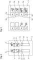
- FIG. 2 shows a schematic representation of a display on the display 14 of the control unit 17 of the work machine 1, which concerns the assignment of hydraulic functions.
- Fig. 2 illustrates the visualization of an assignment made by or selected by the operator between one of the directional control valves of the control device 18 and hydraulic functions to be performed by an adjusting element of the implement 3 to be controlled, as shown on the display 14.
- Reference numerals 30 and 34 denote symbols shown on the display which characterize the respective hydraulic function.
- Symbol 30 describes the hydraulic function of actuating a pivotable rear flap of a tipping trailer by a hydraulically actuated adjusting element.
- Symbol 34 describes the hydraulic function of changing the tipping angle of the loading area by a hydraulically actuated adjusting element.
- Symbols 31 and 35 visualize the directional control valve of the hydraulic control device 18 assigned to the respective hydraulic function.
- Symbol 31 designates the directional control valve whose activation leads to a change in the tipping angle of the tipping trailer.
- Symbol 35 designates the directional control valve whose activation leads to actuation of the corresponding adjustment element.
- Reference numerals 32 and 36 designate symbols of the control elements 13 assigned to the respective directional control valves of the hydraulic control device 18.
- an associated flow indicator 33 or 37 is shown on the display 14, which represents the flow rate of the hydraulic oil flows.
- graphic display elements 33a, 33b and 37a, 37b are shown, which visualize the respective flow rate for the two flow directions of the respective hydraulic valve of the corresponding adjustment element.
- FIG. 3 shows a schematic representation of the display on the display 14 of the control unit 17 of the work machine 1 concerning the assignment of control elements 13.
- Fig. 3 illustrates the visualization of the assignment between a hydraulic sub-function and an associated control element 13.
- Reference numerals 39a and 39b denote the symbols that visualize the hydraulic sub-functions for opening and closing the pivoting rear flap of the tipping trailer, respectively. These sub-functions are effected by the corresponding activation of the associated directional control valve, which controls the hydraulic flow to the adjustment element on the tipping trailer.
- Reference numerals 39c and 39d denote the symbols that visualize the hydraulic sub-functions for adjusting the tipping angle for raising or lowering the loading area of the tipping trailer.
- Each of the hydraulic sub-functions visualized by symbols 39a to 39d is assigned an operating element 13, which in the illustrated embodiment are designed as function keys 38a to 38d. This visualization of the control-related relationships helps to avoid incorrect operation.
- Fig. 4 shows a partial view of an automatically executable sequence shown on the display 14 of the control unit 17, which is assigned to the working device 3.
- the sequence contains the information about the assignment of hydraulic functions to a directional valve of the control device 18 as well as the control element 13 to the respective hydraulic function.
- the working device 3 is designed as a tipping trailer.
- step 1 the hydraulic sub-function of pivoting the rear flap, visualized by the symbol 39a, is displayed by an automated actuation of the function key 38a. The duration of this actuation is shown by a time indication on the display 14.
- step 2 the hydraulic sub-function of raising the loading area, represented by the symbol 39b, is displayed by the automatic actuation of the function key 38b.
- step 3 the hydraulic sub-function of lowering the loading area of the tipping trailer, visualized by symbol 39c, is represented by an automated actuation of function key 38c.
- step 3 the hydraulic subfunction of closing the rear flap, represented by symbol 39d, is represented by the automated actuation of the function key 38d assigned to this function.
Landscapes
- Life Sciences & Earth Sciences (AREA)
- Engineering & Computer Science (AREA)
- Mechanical Engineering (AREA)
- Soil Sciences (AREA)
- Environmental Sciences (AREA)
- Lifting Devices For Agricultural Implements (AREA)
- Operation Control Of Excavators (AREA)
- Management, Administration, Business Operations System, And Electronic Commerce (AREA)
Claims (8)
- Machine de travail agricole (1, 2) comprenant un système d'actionnement hydraulique qui active des vannes de la machine de travail agricole (1, 2) auxquelles sont associés respectivement des raccords de machine (10) auxquels peut être raccordé au moins un outil de travail (3) doté de raccords conjugués (11), aux fins d'activer un élément de réglage à actionnement hydraulique, et comprenant une unité de commande (17) qui comporte des moyens d'entrée et de sortie (16) et qui est reliée au système d'actionnement hydraulique sur le plan de la technique des signaux, sachant que le système d'actionnement hydraulique est conçu de manière à ce que soient directement associés respectivement à une vanne, une fonction hydraulique de l'outil de travail (3) raccordé, au nombre d'au moins un, qui peut être exécutée par l'élément de réglage, et au moins un élément de commande (13) de l'unité de commande (17), lesdites associations étant sauvegardées dans une mémoire de données (20) de la machine de travail agricole (1, 2), de manière à pouvoir les extraire, sachant que le système d'actionnement est conçu pour effectuer les associations en fonction de caractéristiques fonctionnelles de l'outil de travail (3) raccordé, le système d'actionnement étant conçu pour exécuter des séquences spécifiques pour un modèle d'outil attelé de l'outil de travail (3) raccordé, qui sont sauvegardées dans la mémoire de données (20) et définissent des étapes de processus agricoles par des évolutions de puissance dépendant du temps et/ou du trajet, le système d'actionnement étant conçu pour manipuler les évolutions de puissance, dépendant du temps et/ou du trajet, d'une séquence sauvegardée, par le biais d'entrées qui sont reçues depuis l'unité de commande (17),
caractérisée en ce que
le système d'actionnement est conçu pour enregistrer une séquence pour un outil de travail (3), à l'aide d'entrées transmises par l'unité de commande (17), et pour la sauvegarder dans la mémoire de données (20), de manière à pouvoir l'extraire. - Machine de travail agricole (1, 2) selon la revendication 1, caractérisée en ce que le système d'actionnement est conçu pour manipuler les associations sauvegardées d'un outil de travail (3) raccordé, par le biais d'entrées qui sont transmises par l'unité de commande (17) à un dispositif d'actionnement (22).
- Machine de travail agricole (1, 2) selon une des revendications précédentes, caractérisée en ce que l'unité de commande (17) est conçue pour visualiser par un symbole (30, 34) l'association respective de la fonction hydraulique, effectuée par le système d'actionnement.
- Machine de travail agricole selon une des revendications précédentes, caractérisée en ce que l'unité de commande (17) est conçue pour visualiser par un symbole (39a, 39b, 39c, 39d) une fonction partielle associée à l'élément de commande (13, 15) respectif.
- Machine de travail agricole (1, 2) selon une des revendications précédentes, caractérisée en ce que le système d'actionnement est conçu pour effectuer une association d'une fonction hydraulique à une vanne et d'au moins un élément de commande (13, 15) à une vanne, en fonction d'entrées reçues par le biais de l'unité de commande (17).
- Machine de travail agricole (1, 2) selon une des revendications précédentes, caractérisée en ce que le système d'actionnement est conçu pour procéder, lors de la sélection d'un outil de travail (3) raccordé, par une entrée via l'unité de commande (17), à l'ouverture d'un dialogue qui délivre les associations sauvegardées pour l'outil de travail (3) raccordé, par le biais du moyen de sortie (16) de l'unité de commande (17), à des fins de vérification.
- Machine de travail agricole (1, 2) selon une des revendications précédentes, caractérisée en ce que le système d'actionnement est conçu pour ouvrir un dialogue du fait d'une entrée effectuée à l'aide de l'unité de commande (17), lequel dialogue permet de détecter individuellement la catégorie d'outil de travail de l'outil de travail (3) raccordé et d'effectuer l'association d'une fonction hydraulique à une vanne ainsi que l'association d'au moins un élément de commande (13, 13a, 13b, 15) à ladite vanne.
- Procédé pour faire fonctionner une machine de travail agricole (1, 2) comprenant un système d'actionnement hydraulique par lequel sont activées des vannes de la machine de travail agricole (1, 2) auxquelles sont associés respectivement des raccords de machine (10) auxquels peut être raccordé au moins un outil de travail (3) doté de raccords conjugués (11), aux fins d'activer un élément de réglage à actionnement hydraulique, et comprenant une unité de commande (17) qui comporte des moyens d'entrée et de sortie (16) et qui est reliée au système d'actionnement hydraulique sur le plan de la technique des signaux, sachant que la sélection d'un outil de travail (3) a pour effet que sont directement associés respectivement à une vanne, une fonction hydraulique de l'outil de travail (3) raccordé, au nombre d'au moins un, qui est exécutée par l'élément de réglage, et au moins un élément de commande (13, 13a, 13b, 15) de l'unité de commande (17), lesdites associations étant extraites d'une mémoire de données (20) de la machine de travail agricole (1, 2), sachant que le système d'actionnement effectue les associations en fonction de caractéristiques fonctionnelles de l'outil de travail (3) raccordé, le système d'actionnement exécutant des séquences spécifiques pour un modèle d'outil attelé de l'outil de travail (3) raccordé, lesquelles séquences sont sauvegardées dans la mémoire de données (20) et définissent des étapes de processus agricoles par des évolutions de puissance dépendant du temps et/ou du trajet, sachant que le système d'actionnement manipule les évolutions de puissance, dépendant du temps et/ou du trajet, d'une séquence sauvegardée, par le biais d'entrées qui sont reçues depuis l'unité de commande (17),
caractérisée en ce que
le système d'actionnement enregistre une séquence pour un outil de travail (3), à l'aide d'entrées transmises par l'unité de commande (17), et la sauvegarde dans la mémoire de données (20), de manière à pouvoir l'extraire.
Applications Claiming Priority (1)
| Application Number | Priority Date | Filing Date | Title |
|---|---|---|---|
| DE102017110045.8A DE102017110045A1 (de) | 2017-05-10 | 2017-05-10 | Landwirtschaftliche Arbeitsmaschine sowie Verfahren zum Betreiben einer landwirtschaftlichen Arbeitsmaschine |
Publications (2)
| Publication Number | Publication Date |
|---|---|
| EP3400769A1 EP3400769A1 (fr) | 2018-11-14 |
| EP3400769B1 true EP3400769B1 (fr) | 2025-05-07 |
Family
ID=61768177
Family Applications (1)
| Application Number | Title | Priority Date | Filing Date |
|---|---|---|---|
| EP18163860.2A Active EP3400769B1 (fr) | 2017-05-10 | 2018-03-26 | Machine de travail agricole et procédé de fonctionnement d'une machine de travail agricole |
Country Status (3)
| Country | Link |
|---|---|
| EP (1) | EP3400769B1 (fr) |
| DE (1) | DE102017110045A1 (fr) |
| RU (1) | RU2769763C2 (fr) |
Families Citing this family (4)
| Publication number | Priority date | Publication date | Assignee | Title |
|---|---|---|---|---|
| EP3754119B1 (fr) | 2019-06-17 | 2023-08-09 | Kubota Corporation | Véhicule de travail comportant des contrôleurs de soupapes de commande améliorés |
| DE102019122116A1 (de) * | 2019-08-16 | 2021-02-18 | Claas Tractor Sas | Landwirtschaftliches Gespann mit einer Zugmaschine und einem Pflug |
| DE102021116246A1 (de) * | 2021-06-23 | 2022-12-29 | Liebherr-Hydraulikbagger Gmbh | System und Verfahren zur Lokalisierung eines Anbauwerkzeugs |
| DE102023115146B3 (de) | 2023-06-09 | 2024-10-02 | Kässbohrer Geländefahrzeug Aktiengesellschaft | Ziviles Kettenfahrzeug, Verfahren zum Betreiben eines zivilen Kettenfahrzeugs und System mit einem zivilen Kettenfahrzeug |
Citations (2)
| Publication number | Priority date | Publication date | Assignee | Title |
|---|---|---|---|---|
| US6061617A (en) * | 1997-10-21 | 2000-05-09 | Case Corporation | Adaptable controller for work vehicle attachments |
| WO2018098238A1 (fr) * | 2016-11-23 | 2018-05-31 | CNH Industrial America, LLC | Système et procédé destinés à fournir des dispositifs d'entrée reconfigurables pour un véhicule de travail |
Family Cites Families (6)
| Publication number | Priority date | Publication date | Assignee | Title |
|---|---|---|---|---|
| SU933014A1 (ru) * | 1980-11-14 | 1982-06-07 | Московский автомеханический институт | Электрогидравлический привод дл управлени навесными оруди ми трактора |
| US5887669A (en) * | 1997-05-08 | 1999-03-30 | Case Corporation | Auxiliary hydraulic control system |
| US6561076B2 (en) * | 2001-04-30 | 2003-05-13 | Case Corporation | Differential configuration of remote hydraulic valve flow rates for extend and retract modes of operation |
| GB201116867D0 (en) | 2011-09-30 | 2011-11-09 | Agco Sa | Hydraulic apparatus control system |
| US20140298241A1 (en) * | 2013-03-29 | 2014-10-02 | Deere & Company | Retracting shortcut bars, status shortcuts and edit run page sets |
| DE102013008338A1 (de) * | 2013-05-16 | 2014-11-20 | Claas Selbstfahrende Erntemaschinen Gmbh | Kontrollsystem für Anbaugeräte einer landwirtschaftlichen Arbeitsmaschine |
-
2017
- 2017-05-10 DE DE102017110045.8A patent/DE102017110045A1/de not_active Withdrawn
-
2018
- 2018-03-26 EP EP18163860.2A patent/EP3400769B1/fr active Active
- 2018-05-04 RU RU2018116454A patent/RU2769763C2/ru active
Patent Citations (2)
| Publication number | Priority date | Publication date | Assignee | Title |
|---|---|---|---|---|
| US6061617A (en) * | 1997-10-21 | 2000-05-09 | Case Corporation | Adaptable controller for work vehicle attachments |
| WO2018098238A1 (fr) * | 2016-11-23 | 2018-05-31 | CNH Industrial America, LLC | Système et procédé destinés à fournir des dispositifs d'entrée reconfigurables pour un véhicule de travail |
Non-Patent Citations (1)
| Title |
|---|
| ANONYMOUS: "FENDT 720, 722, 724 Vario", FENDT 700 SERIES OPERATOR'S MANUAL, 1 June 2011 (2011-06-01), pages 3PP, 61, 109, 118, 179 - 180, 195,, XP055489300 * |
Also Published As
| Publication number | Publication date |
|---|---|
| DE102017110045A1 (de) | 2018-11-15 |
| RU2769763C2 (ru) | 2022-04-05 |
| RU2018116454A (ru) | 2019-11-05 |
| RU2018116454A3 (fr) | 2021-07-05 |
| EP3400769A1 (fr) | 2018-11-14 |
Similar Documents
| Publication | Publication Date | Title |
|---|---|---|
| EP0714592B1 (fr) | Système de commande pour le réglage de position de dispositifs d'attelage | |
| EP3400769B1 (fr) | Machine de travail agricole et procédé de fonctionnement d'une machine de travail agricole | |
| EP3243368B2 (fr) | Combinaison d'appareil de véhicule de traction ayant un système d'assistance au conducteur | |
| DE102016118205A1 (de) | Zugmaschinen-Geräte-Kombination mit Fahrerassistenzsystem | |
| DE102012220109A1 (de) | Einrichtung zur Erfassung des Betriebszustands einer Arbeitsmaschine | |
| WO2020074043A1 (fr) | Ensemble de rééquipement pour le montage sur une machine agricole | |
| EP3434087B1 (fr) | Procédé d'aide à un opérateur de machine lors du réglage d'une machine de traitement du sol agricole | |
| EP3763182B1 (fr) | Dispositif de commande adaptatif | |
| EP0820688B2 (fr) | Dispositif pour le contrôle au minimum d'un actionneur d'un véhicule utilitaire | |
| DE102021101553A1 (de) | Verfahren zur Kontrolle und/oder Dokumentation eines Arbeitsvorgangs einer selbstfahrenden landwirtschaftlichen Arbeitsmaschine | |
| EP4133925B1 (fr) | Procédé de fonctionnement d'une combinaison véhicule-outil agricole | |
| EP4176702B1 (fr) | Procédé de commande et/ou de réglage d'une machine de distribution agricole | |
| DE102019208346A1 (de) | Landwirtschaftlicher Traktor mit einem an diesen ankuppelbaren Anbaugerät sowie Verfahren zum Betrieb eines landwirtschaftlichen Traktors mit einem an diesen ankuppelbaren Anbaugerät | |
| EP3311639B1 (fr) | Procédé de calcul de grandeurs géométriques et/ou de réglage caractéristiques d'un relevage à trois points | |
| DE102018128096A1 (de) | Verfahren zum gleichzeitigen kombinierten Betrieb mehrerer auch unabhängig voneinander betreibbarer landwirtschaftlicher Geräte | |
| EP3653033B1 (fr) | Procédé de fonctionnement d'une prise de force d'un tracteur agricole doté d'un mécanisme de levage d'éléments rapportés | |
| EP4124220A1 (fr) | Procédé d'aide à un processus d'accouplement à mettre en uvre dans un relevage à trois points | |
| DE102016223189A1 (de) | Verfahren zur Berechnung charakteristischer Geometrie- und/oder Stellgrößen eines Dreipunkt-Krafthebers | |
| EP4292412B1 (fr) | Système d'assistance pour une combinaison de véhicules agricoles | |
| DE102018121644A1 (de) | Bediensystem für eine landwirtschaftliche Maschine und Verfahren zur Vorabkonfiguration eines solchen Bediensystems | |
| EP4683492A1 (fr) | Procédé de reconnaissance d'état des pièces travaillantes d'un outil de travail du sol | |
| DE69108834T2 (de) | Hydraulisches Steuersystem für Werkzeuggruppen. | |
| WO2025237564A1 (fr) | Machine de travail agricole et procédé de fonctionnement d'une machine de travail agricole | |
| DE102004015162A1 (de) | Kombination aus einem Trägerfahrzeug und einem landwirtschaftlichen Arbeitsgerät | |
| EP3229200A1 (fr) | Système d'administration de données de travail et de données opérationnelles d'au moins une machine agricole |
Legal Events
| Date | Code | Title | Description |
|---|---|---|---|
| PUAI | Public reference made under article 153(3) epc to a published international application that has entered the european phase |
Free format text: ORIGINAL CODE: 0009012 |
|
| STAA | Information on the status of an ep patent application or granted ep patent |
Free format text: STATUS: THE APPLICATION HAS BEEN PUBLISHED |
|
| AK | Designated contracting states |
Kind code of ref document: A1 Designated state(s): AL AT BE BG CH CY CZ DE DK EE ES FI FR GB GR HR HU IE IS IT LI LT LU LV MC MK MT NL NO PL PT RO RS SE SI SK SM TR |
|
| AX | Request for extension of the european patent |
Extension state: BA ME |
|
| STAA | Information on the status of an ep patent application or granted ep patent |
Free format text: STATUS: REQUEST FOR EXAMINATION WAS MADE |
|
| 17P | Request for examination filed |
Effective date: 20190514 |
|
| RBV | Designated contracting states (corrected) |
Designated state(s): AL AT BE BG CH CY CZ DE DK EE ES FI FR GB GR HR HU IE IS IT LI LT LU LV MC MK MT NL NO PL PT RO RS SE SI SK SM TR |
|
| STAA | Information on the status of an ep patent application or granted ep patent |
Free format text: STATUS: EXAMINATION IS IN PROGRESS |
|
| 17Q | First examination report despatched |
Effective date: 20210604 |
|
| P01 | Opt-out of the competence of the unified patent court (upc) registered |
Effective date: 20230516 |
|
| GRAP | Despatch of communication of intention to grant a patent |
Free format text: ORIGINAL CODE: EPIDOSNIGR1 |
|
| STAA | Information on the status of an ep patent application or granted ep patent |
Free format text: STATUS: GRANT OF PATENT IS INTENDED |
|
| INTG | Intention to grant announced |
Effective date: 20241115 |
|
| GRAS | Grant fee paid |
Free format text: ORIGINAL CODE: EPIDOSNIGR3 |
|
| GRAA | (expected) grant |
Free format text: ORIGINAL CODE: 0009210 |
|
| STAA | Information on the status of an ep patent application or granted ep patent |
Free format text: STATUS: THE PATENT HAS BEEN GRANTED |
|
| AK | Designated contracting states |
Kind code of ref document: B1 Designated state(s): AL AT BE BG CH CY CZ DE DK EE ES FI FR GB GR HR HU IE IS IT LI LT LU LV MC MK MT NL NO PL PT RO RS SE SI SK SM TR |
|
| REG | Reference to a national code |
Ref country code: GB Ref legal event code: FG4D Free format text: NOT ENGLISH |
|
| REG | Reference to a national code |
Ref country code: CH Ref legal event code: EP |
|
| REG | Reference to a national code |
Ref country code: DE Ref legal event code: R096 Ref document number: 502018015786 Country of ref document: DE |
|
| REG | Reference to a national code |
Ref country code: IE Ref legal event code: FG4D Free format text: LANGUAGE OF EP DOCUMENT: GERMAN |
|
| REG | Reference to a national code |
Ref country code: NL Ref legal event code: MP Effective date: 20250507 |
|
| PG25 | Lapsed in a contracting state [announced via postgrant information from national office to epo] |
Ref country code: FI Free format text: LAPSE BECAUSE OF FAILURE TO SUBMIT A TRANSLATION OF THE DESCRIPTION OR TO PAY THE FEE WITHIN THE PRESCRIBED TIME-LIMIT Effective date: 20250507 Ref country code: PT Free format text: LAPSE BECAUSE OF FAILURE TO SUBMIT A TRANSLATION OF THE DESCRIPTION OR TO PAY THE FEE WITHIN THE PRESCRIBED TIME-LIMIT Effective date: 20250908 Ref country code: ES Free format text: LAPSE BECAUSE OF FAILURE TO SUBMIT A TRANSLATION OF THE DESCRIPTION OR TO PAY THE FEE WITHIN THE PRESCRIBED TIME-LIMIT Effective date: 20250507 |
|
| REG | Reference to a national code |
Ref country code: LT Ref legal event code: MG9D |
|
| PG25 | Lapsed in a contracting state [announced via postgrant information from national office to epo] |
Ref country code: NO Free format text: LAPSE BECAUSE OF FAILURE TO SUBMIT A TRANSLATION OF THE DESCRIPTION OR TO PAY THE FEE WITHIN THE PRESCRIBED TIME-LIMIT Effective date: 20250807 Ref country code: GR Free format text: LAPSE BECAUSE OF FAILURE TO SUBMIT A TRANSLATION OF THE DESCRIPTION OR TO PAY THE FEE WITHIN THE PRESCRIBED TIME-LIMIT Effective date: 20250808 |
|
| PG25 | Lapsed in a contracting state [announced via postgrant information from national office to epo] |
Ref country code: PL Free format text: LAPSE BECAUSE OF FAILURE TO SUBMIT A TRANSLATION OF THE DESCRIPTION OR TO PAY THE FEE WITHIN THE PRESCRIBED TIME-LIMIT Effective date: 20250507 Ref country code: NL Free format text: LAPSE BECAUSE OF FAILURE TO SUBMIT A TRANSLATION OF THE DESCRIPTION OR TO PAY THE FEE WITHIN THE PRESCRIBED TIME-LIMIT Effective date: 20250507 |
|
| PG25 | Lapsed in a contracting state [announced via postgrant information from national office to epo] |
Ref country code: BG Free format text: LAPSE BECAUSE OF FAILURE TO SUBMIT A TRANSLATION OF THE DESCRIPTION OR TO PAY THE FEE WITHIN THE PRESCRIBED TIME-LIMIT Effective date: 20250507 |
|
| PG25 | Lapsed in a contracting state [announced via postgrant information from national office to epo] |
Ref country code: HR Free format text: LAPSE BECAUSE OF FAILURE TO SUBMIT A TRANSLATION OF THE DESCRIPTION OR TO PAY THE FEE WITHIN THE PRESCRIBED TIME-LIMIT Effective date: 20250507 |
|
| PG25 | Lapsed in a contracting state [announced via postgrant information from national office to epo] |
Ref country code: RS Free format text: LAPSE BECAUSE OF FAILURE TO SUBMIT A TRANSLATION OF THE DESCRIPTION OR TO PAY THE FEE WITHIN THE PRESCRIBED TIME-LIMIT Effective date: 20250807 |
|
| PG25 | Lapsed in a contracting state [announced via postgrant information from national office to epo] |
Ref country code: IS Free format text: LAPSE BECAUSE OF FAILURE TO SUBMIT A TRANSLATION OF THE DESCRIPTION OR TO PAY THE FEE WITHIN THE PRESCRIBED TIME-LIMIT Effective date: 20250907 |
|
| PG25 | Lapsed in a contracting state [announced via postgrant information from national office to epo] |
Ref country code: LV Free format text: LAPSE BECAUSE OF FAILURE TO SUBMIT A TRANSLATION OF THE DESCRIPTION OR TO PAY THE FEE WITHIN THE PRESCRIBED TIME-LIMIT Effective date: 20250507 |
|
| PG25 | Lapsed in a contracting state [announced via postgrant information from national office to epo] |
Ref country code: DK Free format text: LAPSE BECAUSE OF FAILURE TO SUBMIT A TRANSLATION OF THE DESCRIPTION OR TO PAY THE FEE WITHIN THE PRESCRIBED TIME-LIMIT Effective date: 20250507 Ref country code: SM Free format text: LAPSE BECAUSE OF FAILURE TO SUBMIT A TRANSLATION OF THE DESCRIPTION OR TO PAY THE FEE WITHIN THE PRESCRIBED TIME-LIMIT Effective date: 20250507 |
|
| PG25 | Lapsed in a contracting state [announced via postgrant information from national office to epo] |
Ref country code: CZ Free format text: LAPSE BECAUSE OF FAILURE TO SUBMIT A TRANSLATION OF THE DESCRIPTION OR TO PAY THE FEE WITHIN THE PRESCRIBED TIME-LIMIT Effective date: 20250507 |
|
| PG25 | Lapsed in a contracting state [announced via postgrant information from national office to epo] |
Ref country code: EE Free format text: LAPSE BECAUSE OF FAILURE TO SUBMIT A TRANSLATION OF THE DESCRIPTION OR TO PAY THE FEE WITHIN THE PRESCRIBED TIME-LIMIT Effective date: 20250507 |
|
| PG25 | Lapsed in a contracting state [announced via postgrant information from national office to epo] |
Ref country code: SK Free format text: LAPSE BECAUSE OF FAILURE TO SUBMIT A TRANSLATION OF THE DESCRIPTION OR TO PAY THE FEE WITHIN THE PRESCRIBED TIME-LIMIT Effective date: 20250507 Ref country code: RO Free format text: LAPSE BECAUSE OF FAILURE TO SUBMIT A TRANSLATION OF THE DESCRIPTION OR TO PAY THE FEE WITHIN THE PRESCRIBED TIME-LIMIT Effective date: 20250507 |
|
| PG25 | Lapsed in a contracting state [announced via postgrant information from national office to epo] |
Ref country code: IT Free format text: LAPSE BECAUSE OF FAILURE TO SUBMIT A TRANSLATION OF THE DESCRIPTION OR TO PAY THE FEE WITHIN THE PRESCRIBED TIME-LIMIT Effective date: 20250507 |
|
| REG | Reference to a national code |
Ref country code: DE Ref legal event code: R097 Ref document number: 502018015786 Country of ref document: DE |
|
| PLBE | No opposition filed within time limit |
Free format text: ORIGINAL CODE: 0009261 |
|
| STAA | Information on the status of an ep patent application or granted ep patent |
Free format text: STATUS: NO OPPOSITION FILED WITHIN TIME LIMIT |
|
| REG | Reference to a national code |
Ref country code: CH Ref legal event code: L10 Free format text: ST27 STATUS EVENT CODE: U-0-0-L10-L00 (AS PROVIDED BY THE NATIONAL OFFICE) Effective date: 20260318 |
|
| PGFP | Annual fee paid to national office [announced via postgrant information from national office to epo] |
Ref country code: DE Payment date: 20260319 Year of fee payment: 9 |
|
| 26N | No opposition filed |
Effective date: 20260210 |
|
| PGFP | Annual fee paid to national office [announced via postgrant information from national office to epo] |
Ref country code: FR Payment date: 20260320 Year of fee payment: 9 |