EP3400832A1 - Montagewerkzeug und verfahren zur montage einer führungsschiene an einem plattenförmigen möbelteil - Google Patents
Montagewerkzeug und verfahren zur montage einer führungsschiene an einem plattenförmigen möbelteil Download PDFInfo
- Publication number
- EP3400832A1 EP3400832A1 EP18171585.5A EP18171585A EP3400832A1 EP 3400832 A1 EP3400832 A1 EP 3400832A1 EP 18171585 A EP18171585 A EP 18171585A EP 3400832 A1 EP3400832 A1 EP 3400832A1
- Authority
- EP
- European Patent Office
- Prior art keywords
- guide rail
- plate
- furniture part
- shaped
- assembly tool
- Prior art date
- Legal status (The legal status is an assumption and is not a legal conclusion. Google has not performed a legal analysis and makes no representation as to the accuracy of the status listed.)
- Granted
Links
Images




Classifications
-
- A—HUMAN NECESSITIES
- A47—FURNITURE; DOMESTIC ARTICLES OR APPLIANCES; COFFEE MILLS; SPICE MILLS; SUCTION CLEANERS IN GENERAL
- A47B—TABLES; DESKS; OFFICE FURNITURE; CABINETS; DRAWERS; GENERAL DETAILS OF FURNITURE
- A47B88/00—Drawers for tables, cabinets or like furniture; Guides for drawers
- A47B88/40—Sliding drawers; Slides or guides therefor
- A47B88/423—Fastening devices for slides or guides
Definitions
- the present invention relates to a mounting tool for mounting a guide rail on a plate-shaped furniture part, comprising a molded body with at least one receptacle for fixing a guide rail, and a method for mounting a guide rail on a plate-shaped furniture part.
- positioning guides for guide rails to position them at a predetermined distance from a front edge of a plate-shaped furniture part.
- the guide rail can be applied to a contact surface of the positioning aid.
- the assembly tool comprises a shaped body with at least one receptacle for fixing a guide rail and an angle-shaped abutment portion, which can be applied to an end edge and a surface of the plate-shaped furniture part.
- a guide rail can be securely positioned on a plate-shaped furniture part, wherein a movement of the guide rail on the clamping fixing with the mounting tool is possible.
- the assembly tool for example, both Fix an upper guide rail to a top floor as well as a lower guide rail to a floor of a cabinet cabinet.
- the assembly tool can be used more flexibly for different profile cross sections.
- the guide rail can in each case be fixed in a clamping manner in or on a receptacle of the shaped body, for example via bendable latching webs or elastic elements which are provided on the receptacle.
- a spring element is provided, which is provided for clamping fixing of the molded body to a plate-shaped furniture part.
- the mounting tool can be positioned together with the guide rail on the plate-shaped furniture part, and the fitter can then release the assembly tool and make the attachment of the guide rail.
- the spring element can be fixed in different connection positions on the molding, so that the assembly tool for different thickness plate-shaped furniture parts can be used or possibly even on the plate-shaped furniture part additional components, such as strips, can be positioned and held on the mounting tool to this then to fix together with the guide rail on the plate-shaped furniture part.
- the spring element may have a foot portion which can be inserted or inserted at different receptacles of the molded body in order to make a simple alignment of the spring element can.
- the spring element is formed integrally with the molded body and can be separated from the molded body by severing a predetermined breaking point, in order then to be mounted again on the molded body at predetermined connecting positions. This facilitates the production of the assembly tool, which can be produced in one piece with the molded body and the spring element, for example by injection molding or extrusion process, in particular of plastic.
- a handle opening or handle recess can be formed in the molded body in order to be able to grip and handle a guide rail securely over the molded body.
- a guide rail is first fixed in or on a receptacle of a shaped body, in order then to position an angle-shaped contact section on a front edge and a surface of a plate-shaped furniture part, in order to then guide the guide rail on the to fix plate-shaped furniture part.
- a spring element is provided on the molded body, which is applied to the opposite side to the guide rail to the plate-shaped furniture part, so that the positioning of the guide rail can be done both on a bottom and on an upper side of a plate-shaped furniture part in the installed position before then the fitter fixes the guide rail on the plate-shaped furniture part.
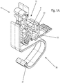
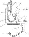
- An assembly tool 10 comprises a molded body 11 made of plastic, which may be produced, for example, by injection molding or extrusion process.
- the molded body 11 comprises a first groove-shaped receptacle 12 for fixing a portion of a guide rail in order to position it on a plate-shaped furniture part.
- a second groove-shaped receptacle 13 is provided for inserting a web of a guide rail, which is aligned at an angle to the first receptacle 12.
- an extended wall portion 17 is formed, which serves as a detent web and a groove-shaped receptacle 18 which is latched to a web of a guide rail.
- the wall portion 17 is also resiliently formed on the molded body 11 to facilitate disassembly of the mounting tool 10 after attachment of the rail 40 on the furniture body.
- An angle-shaped abutment portion 14 is further formed on the mounting tool 10, which has a first leg 15 and a second leg 16 aligned at right angles thereto, which is placed on a plate-shaped furniture part for positioning a guide rail which is held on one of the two receptacles 12 or 13 ,
- the legs 15 or 16 may optionally bear against the entire surface of the plate-shaped furniture part or only on individual projections, in particular strip-shaped projections.
- the molded body 11 is formed integrally with a spring element 20, which is connected via a predetermined breaking point 19 with the remaining molded body 11.
- the spring element 20 comprises a foot portion 21, which is wider at least in sections than a curved web 22, which is substantially arcuate or O-shaped and has an angled abutment portion 23 on one leg.
- FIG. 2 the assembly tool 10 is shown in a position in which the spring element 20, which is formed integrally with the molded body 11, has been separated therefrom at the predetermined breaking point 19.
- the fitter can now reassemble the spring element 20 and the molded body 11, wherein two receptacles 24 and 25 are formed on a rear side of the angular abutment section 14, in particular on the leg 16, into which the foot section 21 can be inserted or inserted.
- a first receptacle 24 is located adjacent to the corner region of the angular contact section 14, and a second receptacle 25 in a central region of the leg 16.
- the spring element 20 are fixed in the second receptacle 25, so that now the bent abutment portion 23 is arranged at a greater distance to the leg 15.
- the assembly tool 10 is shown to fix a guide rail 30 to a plate-shaped furniture part 5, for example.
- the guide rail 30 is formed angularly in cross section, wherein a leg 31 is inserted into the receptacle 12 and fixed there by clamping.
- the other leg of the guide rail 30 has a surface which is aligned substantially flush with the leg 15.
- the assembly tool 10 can now together with the guide rail 30 according to FIG. 5B be positioned so that the guide rail 30 is positioned and held on an underside of the plate-shaped furniture part 5 via the mounting tool 10. In this case, the distance of the guide rail 30 from the front end edge of the plate-shaped furniture part 5 is predetermined via the angular contact section 14.
- the mounting tool 10 is fixed together with the guide rail 30 by clamping to the plate-shaped furniture part 5, wherein in the representation of the present application, the curved shape of the spring element 20th not shown.
- the bent abutment portion 23 is located on the upper side of the plate-shaped furniture part 5, while the guide rail 30 is provided on the opposite underside of the plate-shaped furniture part 5.
- the assembly tool 10 is used for mounting a guide rail 30, which is attached to an upper side of a plate-shaped Furniture part 5 is to be mounted, which has a base 6 or another element on the underside.
- the spring element 20 can not be used to surround the plate-shaped furniture part 5 in a U-shape. Even without the spring element 20 can be applied to a front end edge of the plate-shaped furniture part 5 for mounting the guide rail 30 on the upper side of the plate-shaped furniture part, the angular positioning portion 30 to position the guide rail 30 and then fix, for example.
- the guide rail 30 can be held by two assembly tools 10, each having a hollow handle opening 26.
- FIGS. 7A and 7B the assembly tool is shown in which a modified guide rail 40 is mounted on a plate-shaped furniture part 5.
- the guide rail 40 is U-shaped in cross-section and has a portion 41 which is inserted into the receptacle 13 on the molded body 11.
- the other, designed as a vertical web leg is inserted with an end face in the groove-shaped receptacle 18 on the wall portion 17, so that the guide rail 40 is fixed by clamping to the molded body 11.
- the guide rail 40 can now be similar to in FIG.
- the spring element 20 ensures that the mounting tool 10 is clamped together with the guide rail 40 to the plate-shaped furniture part 5, so that the fitter now on other fasteners, the guide rail 40 at the bottom of the plate-shaped Furniture part 5 can fix.
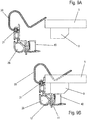
- FIGS 9A and 9B the assembly of the U-shaped guide rail 40 is shown, which is fixed to the receptacle 13 of the mounting tool 10.
- the guide rail 40 can via the spring element 20 clamped to the plate-shaped furniture part 5 are fixed to the strip 9, to then fix the guide rail 40 via fastening means on the bar 9, wherein optionally also the bar 9 is fixed together with the guide rail 40 on the plate-shaped furniture part 5.
- the assembly of the guide rail 30 is shown via two assembly tools 10, spaced from each other hold the guide rail 30 to fix them to a floor as a plate-shaped furniture part 5 of a cupboard-shaped piece of furniture 1.
- the furniture 1 comprises a furniture body with a top floor 2, a bottom and a middle partition wall 4 connecting the top floor 2 and the floor, and outer side walls 3 connecting the floor to the top floor 2.
- the floor is further spaced from a substrate and positioned over a pedestal 6.
- the guide rail 30 can be positioned via the mounting tool 10 on the ground and then fixed by fastening means, as shown in the Figures 5 and 6 is shown.
- FIGS. 8 or 9 take place, wherein the guide rail 30 or 40 takes place optionally on the underside or the top of the plate-shaped furniture part 5.
- the assembly tool 10 can thus be added in the delivery of a cupboard furniture, so that the fitter or end user can easily align the guide rail 30 or 40 exactly and fix.
Landscapes
- Furniture Connections (AREA)
Abstract
Description
- Die vorliegende Erfindung betrifft ein Montagewerkzeug zur Montage einer Führungsschiene an einem plattenförmigen Möbelteil, mit einem Formkörper mit mindestens einer Aufnahme zur Fixierung einer Führungsschiene, und ein Verfahren zur Montage einer Führungsschiene an einem plattenförmigen Möbelteil.
- Es gibt Positionierhilfen für Führungsschienen, um diese in einem vorbestimmten Abstand zu einer Stirnkante eines plattenförmigen Möbelteils zu positionieren. Bei solchen Positionierhilfen kann die Führungsschiene an einer Anlagefläche der Positionierhilfe angelegt werden. Bei der Montage ist es allerdings notwendig, die Führungsschiene loszulassen, um diese dann über Schrauben oder andere Befestigungsmittel an einem plattenförmigen Möbelteil zu fixieren. Dies ist gerade bei der Montage von Führungsschienen an einer Unterseite eines plattenförmigen Möbelteils schwierig.
- Es ist daher Aufgabe der vorliegenden Erfindung, ein Montagewerkzeug zur Montage einer Führungsschiene und ein Verfahren zur Montage einer Führungsschiene an einem plattenförmigen Möbelteil bereitzustellen, die eine einfache Handhabung der Führungsschiene ermöglichen.
- Diese Aufgabe wird mit einem Montagewerkzeug mit den Merkmalen des Anspruchs 1 und einem Verfahren mit den Merkmalen des Anspruchs 10 gelöst.
- Das erfindungsgemäße Montagewerkzeug umfasst einen Formkörper mit mindestens einer Aufnahme zur Fixierung einer Führungsschiene und einen winkelförmigen Anlageabschnitt, der an eine Stirnkante und eine Oberfläche des plattenförmigen Möbelteils anlegbar ist. Dadurch kann eine Führungsschiene sicher an einem plattenförmigen Möbelteil positioniert werden, wobei auch eine Bewegung der Führungsschiene über die klemmende Fixierung mit dem Montagewerkzeug möglich ist.
- Vorzugsweise sind an dem Formkörper mindestens zwei beabstandete Aufnahmen zur Fixierung von Führungsschienen mit einem unterschiedlichen Profilquerschnitt vorgesehen. Dadurch kann das Montagewerkzeug bspw. sowohl eine obere Führungsschiene an einem Oberboden als auch eine untere Führungsschiene an einem Boden eines Schrankmöbels fixieren. Zudem lässt sich das Montagewerkzeug flexibler für unterschiedliche Profilquerschnitte einsetzen. Die Führungsschiene kann dabei jeweils klemmend in oder an einer Aufnahme des Formkörpers fixiert werden, bspw. über biegbare Raststege oder elastische Elemente, die an der Aufnahme vorgesehen sind.
- Gemäß einer weiteren Ausgestaltung ist ein Federelement vorgesehen, das zur klemmenden Fixierung des Formkörpers an einem plattenförmigen Möbelteil vorgesehen ist. Dadurch kann das Montagewerkzeug zusammen mit der Führungsschiene an dem plattenförmigen Möbelteil positioniert werden, und der Monteur kann dann das Montagewerkzeug loslassen und die Befestigung der Führungsschiene vornehmen. Das Federelement kann dabei in unterschiedlichen Verbindungspositionen an dem Formkörper fixiert werden, sodass das Montagewerkzeug für unterschiedlich dicke plattenförmige Möbelteile eingesetzt werden kann oder ggf. an dem plattenförmigen Möbelteil noch zusätzliche Bauteile, wie Leisten, über das Montagewerkzeug positioniert und gehalten werden können, um diese dann zusammen mit der Führungsschiene an dem plattenförmigen Möbelteil zu fixieren. Das Federelement kann dabei einen Fußabschnitt aufweisen, der an unterschiedlichen Aufnahmen des Formkörpers einsteckbar oder einschiebbar ist, um eine einfache Ausrichtung des Federelementes vornehmen zu können.
- In einer weiteren Ausgestaltung ist das Federelement integral mit dem Formkörper ausgebildet und ist durch Durchtrennen einer Sollbruchstelle von dem Formkörper trennbar, um dann an vorbestimmten Verbindungspositionen wieder an dem Formkörper montiert zu werden. Dies erleichtert die Herstellung des Montagewerkzeuges, das mit dem Formkörper und dem Federelement einstückig hergestellt werden kann, bspw. durch Spritzgussverfahren oder Extrusionsverfahren, insbesondere aus Kunststoff.
- Für eine einfache Handhabung kann in dem Formkörper eine Grifföffnung oder Griffaussparung ausgebildet sein, um dann über den Formkörper eine Führungsschiene sicher greifen und handhaben zu können.
- Bei dem erfindungsgemäßen Verfahren wird zunächst eine Führungsschiene in oder an einer Aufnahme eines Formkörpers fixiert, um dann einen winkelförmigen Anlageabschnitt an einer Stirnkante und einer Oberfläche eines plattenförmigen Möbelteils zu positionieren, um dann die Führungsschiene an dem plattenförmigen Möbelteil zu fixieren. Dies vereinfacht die Handhabung, wobei eine Führungsschiene vorzugsweise über zwei beabstandete Montagewerkzeuge mit einem Formkörper ausgerichtet wird. Vorzugsweise ist dabei an dem Formkörper ein Federelement vorgesehen, das auf der zu der Führungsschiene gegenüberliegenden Seite an das plattenförmige Möbelteil angelegt wird, sodass die Positionierung der Führungsschiene sowohl an einer Unterseite als auch an einer Oberseite eines plattenförmigen Möbelteils in der Einbauposition erfolgen kann, bevor dann der Monteur die Führungsschiene an dem plattenförmigen Möbelteil fixiert.
- Die Erfindung wird nachfolgend anhand mehrerer Ausführungsbeispiele mit Bezug auf die beigefügten Zeichnungen näher erläutert. Es zeigen:
- Figuren 1A und 1B
- zwei Ansichten eines erfindungsgemäßen Montagewerkzeugs;
- Figur 2
- eine perspektivische Ansicht des Montagewerkzeugs der
Figur 1 nach dem Abtrennen des Federelementes; - Figur 3
- eine Ansicht des Montagewerkzeugs mit angestecktem Federelement;
- Figur 4
- eine Ansicht des Montagewerkzeugs mit angestecktem Federelement;
- Figuren 5A und 5B
- zwei Ansichten des Montagewerkzeugs mit einer Führungsschiene bei der Positionierung an einem plattenförmigen Möbelteil;
- Figuren 6A und 6B
- zwei Ansichten des Montagewerkzeugs bei der Montage einer Führungsschiene;
- Figuren 7A und 7B
- zwei Ansichten des Montagewerkzeugs bei der Montage einer modifizierten Führungsschiene;
- Figuren 8A und 8B
- zwei Ansichten des Montagewerkzeugs bei der Montage einer Führungsschiene mit einer zusätzlichen Leiste;
- Figur 9A und 9B
- zwei Ansichten des Montagewerkzeugs bei der Montage einer modifizierten Führungsschiene und einer zusätzlichen Leiste;
- Figuren 10A und 10B
- zwei Ansichten bei der Montage einer Führungsschiene an einem Schrankmöbel, und
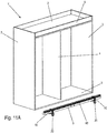
- Figuren 11A und 11B
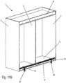
- zwei Ansichten bei der Montage einer Führungsschiene an einem modifizierten Schrankmöbel.
- Ein Montagewerkzeug 10 umfasst einen Formkörper 11 aus Kunststoff, der bspw. im Spritzgussverfahren oder Extrusionsverfahren hergestellt sein kann. Der Formkörper 11 umfasst eine erste nutförmige Aufnahme 12 zum Fixieren eines Abschnittes einer Führungsschiene, um diese an einem plattenförmigen Möbelteil zu positionieren. Ferner ist eine zweite nutförmige Aufnahme 13 zum Einfügen eines Steges einer Führungsschiene vorgesehen, die winklig zu der ersten Aufnahme 12 ausgerichtet ist. An der zweiten Aufnahme 13 ist ein verlängerter Wandabschnitt 17 ausgebildet, der als Raststeg dient und eine nutförmige Aufnahme 18 aufweist, der an einem Steg einer Führungsschiene verrastbar ist. Der Wandabschnitt 17 ist zudem federnd am Formkörper 11 ausgebildet um eine Demontage des Montagewerkzeugs 10 nach Befestigung der Schiene 40 am Möbelkorpus zu erleichtern.
- An dem Montagewerkzeug 10 ist ferner ein winkelförmiger Anlageabschnitt 14 ausgebildet, der einen ersten Schenkel 15 und einen rechtwinklig dazu ausgerichteten zweiten Schenkel 16 aufweist, die zur Positionierung einer Führungsschiene, die an einer der beiden Aufnahmen 12 oder 13 gehalten ist, an ein plattenförmiges Möbelteil anzulegen. Die Schenkel 15 oder 16 können dabei wahlweise vollflächig an dem plattenförmigen Möbelteil anliegen oder nur über einzelne Vorsprünge, insbesondere streifenförmige Vorsprünge.
- Der Formkörper 11 ist integral mit einem Federelement 20 ausgebildet, das über eine Sollbruchstelle 19 mit dem übrigen Formkörper 11 verbunden ist. Das Federelement 20 umfasst einen Fußabschnitt 21, der zumindest abschnittsweite breiter ausgebildet ist als ein gekrümmter Steg 22, der im Wesentlichen bogenförmig oder O-förmig verläuft und an einem Schenkel einen abgewinkelten Anlageabschnitt 23 aufweist.
- In
Figur 2 ist das Montagewerkzeug 10 in einer Position gezeigt, in der das Federelement 20, das integral mit dem Formkörper 11 ausgebildet ist, von diesem an der Sollbruchstelle 19 abgetrennt wurde. Der Monteur kann das Federelement 20 und den Formkörper 11 nun wieder zusammenfügen, wobei an einer Rückseite des winkelförmigen Anlageabschnittes 14, insbesondere an dem Schenkel 16, zwei Aufnahmen 24 und 25 ausgebildet sind, in die der Fußabschnitt 21 einschiebbar oder einsteckbar ist. Eine erste Aufnahme 24 befindet sich dabei benachbart zu dem Eckbereich des winkelförmigen Anlageabschnittes 14, und eine zweite Aufnahme 25 in einem mittleren Bereich des Schenkels 16. Dadurch kann das Federelement 20 gemäßFigur 3 in der ersten Aufnahme 24 montiert werden, sodass der Anlageabschnitt 23 in einem kurzen Abstand zu dem Schenkel 15 angeordnet ist. Alternativ kann gemäßFigur 4 das Federelement 20 in der zweiten Aufnahme 25 fixiert werden, sodass nun der gebogene Anlageabschnitt 23 in einem größeren Abstand zu dem Schenkel 15 angeordnet ist. - In den
Figuren 5A und 5B ist das Montagewerkzeug 10 gezeigt, um eine Führungsschiene 30 an einem plattenförmigen Möbelteil 5, bspw. einem Boden oder Oberboden eines Schrankmöbels, zu fixieren. Die Führungsschiene 30 ist im Querschnitt winkelförmig ausgebildet, wobei ein Schenkel 31 in die Aufnahme 12 eingesteckt und dort klemmend fixiert ist. Der andere Schenkel der Führungsschiene 30 besitzt eine Oberfläche, die im Wesentlichen flächenbündig mit dem Schenkel 15 ausgerichtet ist. Das Montagewerkzeug 10 kann nun zusammen mit der Führungsschiene 30 gemäßFigur 5B so positioniert werden, dass über das Montagewerkzeug 10 die Führungsschiene 30 an einer Unterseite des plattenförmigen Möbelteils 5 positioniert und gehalten ist. Über den winkelförmigen Anlageabschnitt 14 wird dabei der Abstand der Führungsschiene 30 von der vorderen Stirnkante des plattenförmigen Möbelteils 5 vorgegeben. Durch das Federelement 20, das mit dem Fußabschnitt 21 in der Aufnahme 12 des Formkörpers 11 fixiert ist, wird das Montagewerkzeug 10 zusammen mit der Führungsschiene 30 klemmend an dem plattenförmigen Möbelteil 5 fixiert, wobei in der Darstellung der vorliegenden Anmeldung die gebogene Form des Federelementes 20 nicht dargestellt ist. In der montierten Position liegt der gebogene Anlageabschnitt 23 an der Oberseite des plattenförmigen Möbelteils 5 an, während die Führungsschiene 30 an der gegenüberliegenden Unterseite des plattenförmigen Möbelteils 5 vorgesehen ist. - In den
Figuren 6A und 6B wird das Montagewerkzeug 10 zur Montage einer Führungsschiene 30 eingesetzt, die an einer Oberseite eines plattenförmigen Möbelteils 5 montiert werden soll, das an der Unterseite einen Sockel 6 oder ein anderes Element aufweist. Dadurch kann das Federelement 20 nicht eingesetzt werden, um das plattenförmige Möbelteil 5 U-förmig zu umgreifen. Auch ohne das Federelement 20 kann zur Montage der Führungsschiene 30 an der Oberseite des plattenförmigen Möbelteils der winkelförmige Anlageabschnitt an eine Vorderstirnkante des plattenförmigen Möbelteils 5 angelegt werden, um die Führungsschiene 30 zu positionieren und dann zu fixieren, bspw. über Schrauben, Klebebänder oder andere Befestigungsmittel. Die Führungsschiene 30 kann dabei über zwei Montagewerkzeuge 10 gehalten werden, die jeweils eine hohle Grifföffnung 26 aufweisen. - In den
Figuren 7A und 7B ist das Montagewerkzeug gezeigt, bei dem eine modifizierte Führungsschiene 40 an einem plattenförmigen Möbelteil 5 montiert wird. Die Führungsschiene 40 ist im Querschnitt U-förmig ausgebildet und weist einen Abschnitt 41 auf, der in die Aufnahme 13 an dem Formkörper 11 eingesteckt ist. Der andere, als Vertikalsteg ausgebildete Schenkel, ist mit einer Stirnseite in der nutförmigen Aufnahme 18 an dem Wandabschnitt 17 eingefügt, sodass die Führungsschiene 40 klemmend an dem Formkörper 11 fixiert ist. Die Führungsschiene 40 kann nun ähnlich wie inFigur 5 an einer Unterseite des plattenförmigen Möbelteils 5 positioniert werden, wobei das Federelement 20 dafür sorgt, dass das Montagewerkzeug 10 zusammen mit der Führungsschiene 40 an dem plattenförmigen Möbelteil 5 klemmend gehalten ist, sodass der Monteur nun über andere Befestigungsmittel die Führungsschiene 40 an der Unterseite des plattenförmigen Möbelteils 5 fixieren kann. - In den
Figuren 8A und 8B ist die Montage der Führungsschiene 30 an einem plattenförmigen Möbelteil 5 gezeigt, bei dem an der Unterseite des plattenförmigen Möbelteils 5 eine zusätzliche Leiste 9 oder ein Abstandshalter vorgesehen ist. Dadurch vergrößert sich der Abstand zwischen einer Oberseite des plattenförmigen Möbelteils 5 und einer Unterseite der Leiste 9, wobei alternativ auch eine dickere Möbelplatte für den größeren Abstand sorgen kann. Das Federelement 20 wird daher mit dem Fußabschnitt 21 in die zweite Aufnahme 25 eingefügt, sodass nun die Führungsschiene 30 gemäßFigur 8B an der Unterseite der Leiste 9 positioniert und über das Montagewerkzeug 10 klemmend gehalten werden kann. - In den
Figuren 9A und 9B ist die Montage der U-förmigen Führungsschiene 40 gezeigt, die an der Aufnahme 13 des Montagewerkzeugs 10 fixiert ist. Auch die Führungsschiene 40 kann über das Federelement 20 klemmend an dem plattenförmigen Möbelteil 5 mit der Leiste 9 fixiert werden, um dann die Führungsschiene 40 über Befestigungsmittel an der Leiste 9 zu fixieren, wobei optional auch die Leiste 9 zusammen mit der Führungsschiene 40 an dem plattenförmigen Möbelteil 5 fixiert wird. - In den
Figuren 10A und10B ist die Montage der Führungsschiene 30 über zwei Montagewerkzeuge 10 gezeigt, die beabstandet voneinander die Führungsschiene 30 halten, um diese an einem Boden als plattenförmiges Möbelteil 5 eines schrankförmigen Möbels 1 zu fixieren. Das Möbel 1 umfasst einen Möbelkorpus mit einem Oberboden 2, einem Boden und einer den Oberboden 2 und den Boden verbindenden mittleren Trennwand 4, sowie äußere Seitenwände 3, die den Boden mit dem Oberboden 2 verbinden. Der Boden ist ferner beabstandet von einem Untergrund angeordnet und über einem Sockel 6 positioniert. Die Führungsschiene 30 kann über das Montagewerkzeug 10 an dem Boden positioniert und dann über Befestigungsmittel festgelegt werden, wie dies in denFiguren 5 und6 gezeigt ist. - In den
Figuren 11A und11B ist ein auf den Oberboden abgestelltes, also im Gegensatz zu denFiguren 10 um 180° Grad gedrehtes Möbel 1' gezeigt. Zur Montage der Führungsschiene 40 werden zwei Montagewerkzeuge 10 eingesetzt, die die Führungsschiene 40 zusammen mit einer Leiste 9 an einer Unterseite des Oberbodens positionieren, um dann die Führungsschiene 40 zusammen mit der Leiste 9 an dem Oberboden festzulegen. Die Montage kann daher wie in denFiguren 8 oder9 erfolgen, wobei die Führungsschiene 30 oder 40 wahlweise an der Unterseite oder der Oberseite des plattenförmigen Möbelteils 5 erfolgt. - Das Montagewerkzeug 10 kann somit bei der Auslieferung eines Schrankmöbels zugegeben werden, damit der Monteur oder Endverbraucher auf einfache Weise die Führungsschiene 30 oder 40 exakt ausrichten und fixieren kann.
-
- 1, 1'
- Möbel
- 2
- Oberboden
- 3
- Seitenwand
- 4
- Trennwand
- 5
- Möbelteil
- 6
- Sockel
- 9
- Leiste
- 10
- Montagewerkzeug
- 11
- Formkörper
- 12
- Aufnahme
- 13
- Aufnahme
- 14
- Anlageabschnitt
- 15
- Schenkel
- 16
- Schenkel
- 17
- Wandabschnitt
- 18
- Aufnahme
- 19
- Sollbruchstelle
- 20
- Federelement
- 21
- Fußabschnitt
- 22
- Steg
- 23
- Anlageabschnitt
- 24
- Aufnahme
- 25
- Aufnahme
- 26
- Grifföffnung
- 30
- Führungsschiene
- 31
- Schenkel
- 40
- Führungsschiene
- 41
- Abschnitt
Claims (12)
- Montagewerkzeug (10) zur Montage einer Führungsschiene (30, 40) an einem plattenförmigen Möbelteil (5), mit einem Formkörper (11) mit mindestens einer Aufnahme (12, 13) zur Fixierung einer Führungsschiene (30, 40) und einem winkelförmigen Anlageabschnitt (14), der an eine Stirnkante und eine Oberfläche des plattenförmigen Möbelteils (5) anlegbar ist.
- Montagewerkzeug nach Anspruch 1, dadurch gekennzeichnet, dass an dem Formkörper (11) mindestens zwei beabstandete Aufnahmen (12, 13) zur Fixierung von Führungsschienen (30, 40) mit unterschiedlichem Profilquerschnitt vorgesehen sind.
- Montagewerkzeug nach Anspruch 1 oder 2, dadurch gekennzeichnet, dass die Führungsschiene (30, 40) an oder in der Aufnahme (12, 13) klemmend fixierbar ist.
- Montagewerkzeug nach einem der vorgehenden Ansprüche, dadurch gekennzeichnet, dass ein Federelement (20) vorgesehen ist, das zur klemmenden Fixierung des Formkörpers (11) an dem plattenförmigen Möbelteil (5) vorgesehen ist.
- Montagewerkzeug nach Anspruch 4, dadurch gekennzeichnet, dass das Federelement (20) in unterschiedlichen Verbindungspositionen (24, 25) an den Formkörpern (11) fixierbar ist.
- Montagewerkzeug nach Anspruch 4 oder 5, dadurch gekennzeichnet, dass das Federelement (20) integral mit dem Formkörper (11) ausgebildet ist und nach Durchtrennen einer Sollbruchstelle (19) an dem Formkörper (11) montierbar ist.
- Montagewerkzeug nach einem der vorgehenden Ansprüche, dadurch gekennzeichnet, dass an dem Formkörper (11) eine Grifföffnung (26) ausgebildet ist.
- Montagewerkzeug nach einem der vorgehenden Ansprüche, dadurch gekennzeichnet, dass das Federelement (20) einen Fußabschnitt (21) aufweist, der in eine Aufnahme (24, 25) an dem Formkörper (11) einsteckbar oder einschiebbar ist.
- Montagewerkzeug nach einem der vorgehenden Ansprüche, dadurch gekennzeichnet, dass der Formkörper (11) aus Kunstsoff hergestellt ist, vorzugsweise im Spritzguss- oder Extrusionsverfahren.
- Verfahren zur Montage einer Führungsschiene (30, 40) an einem plattenförmigen Möbelteil (5), mit den folgenden Schritten:- Fixieren der Führungsschiene (30, 40) an oder in einer Aufnahme (12, 13) eines Formkörpers (11);- Positionieren eines winkelförmigen Anlageabschnittes (14) an einer Stirnkante und einer Oberfläche des plattenförmigen Möbelteils (5) und- Fixieren der Führungsschiene (30, 40) an dem plattenförmigen Möbelteil.
- Verfahren nach Anspruch 10, dadurch gekennzeichnet, dass an dem Formkörper (11) ein Federelement (20) vorgesehen ist, dass auf der zu der Führungsschiene (30, 40) gegenüberliegenden Seite an dem plattenförmigen Möbelteil angelegt wird.
- Verfahren nach Anspruch 10 oder 11, dadurch gekennzeichnet, dass die Führungsschiene (30, 40) an einer Unterseite des plattenförmigen Möbelteils (5) über mindestens zwei Formkörper (11) gehalten wird.
Applications Claiming Priority (1)
| Application Number | Priority Date | Filing Date | Title |
|---|---|---|---|
| DE102017110329.5A DE102017110329A1 (de) | 2017-05-12 | 2017-05-12 | Montagewerkzeug und Verfahren zur Montage einer Führungsschiene an einem plattenförmigen Möbelteil |
Publications (2)
| Publication Number | Publication Date |
|---|---|
| EP3400832A1 true EP3400832A1 (de) | 2018-11-14 |
| EP3400832B1 EP3400832B1 (de) | 2020-04-15 |
Family
ID=62148228
Family Applications (1)
| Application Number | Title | Priority Date | Filing Date |
|---|---|---|---|
| EP18171585.5A Active EP3400832B1 (de) | 2017-05-12 | 2018-05-09 | Montagewerkzeug und verfahren zur montage einer führungsschiene an einem plattenförmigen möbelteil |
Country Status (2)
| Country | Link |
|---|---|
| EP (1) | EP3400832B1 (de) |
| DE (1) | DE102017110329A1 (de) |
Families Citing this family (1)
| Publication number | Priority date | Publication date | Assignee | Title |
|---|---|---|---|---|
| DE102023117386A1 (de) | 2023-06-30 | 2025-01-02 | Paul Hettich Gmbh & Co. Kg | Verfahren zur Montage eines Funktionsbeschlages und Bausatz |
Citations (6)
| Publication number | Priority date | Publication date | Assignee | Title |
|---|---|---|---|---|
| DE4301327A1 (en) * | 1992-02-05 | 1993-08-12 | Fulterer Gmbh | Method of fitting a guide rail to sliding drawer - has spring catch fitted to underside of drawer which engages slot in rail and holds it in place |
| ES2112622T3 (es) * | 1994-07-13 | 1998-04-01 | Alfit Ag | Dispositivo para la sujecion de una guia para una corredera de extraccion en un cajon de un mueble. |
| US20050102816A1 (en) * | 2003-09-30 | 2005-05-19 | Neil Ziegmann | Slide mounting tools and methods of using same |
| US20090261700A1 (en) * | 2008-04-18 | 2009-10-22 | Ken-Ching Chen | Positioning device for a drawer |
| US20110107615A1 (en) * | 2009-11-09 | 2011-05-12 | Neil Ziegmann | Slide mounting tool and method of use |
| EP2912969A1 (de) * | 2012-10-24 | 2015-09-02 | Segos Co., Ltd. | Vorrichtung zur anbringung oder entnahme eines schiebers für eine schublade |
Family Cites Families (3)
| Publication number | Priority date | Publication date | Assignee | Title |
|---|---|---|---|---|
| AT380777B (de) * | 1983-11-11 | 1986-07-10 | Fulterer Gmbh | Anschlagwerkzeug zur winkelgerechten montage von korpusschienen von schubladenfuehrungen |
| AT380778B (de) * | 1984-11-19 | 1986-07-10 | Blum Gmbh Julius | Anschlaglehre |
| DE202017100195U1 (de) * | 2016-01-21 | 2017-02-22 | Inter Ikea Systems B.V. | Systeme und Vorrichtungen zur Verbindung von Regalen |
-
2017
- 2017-05-12 DE DE102017110329.5A patent/DE102017110329A1/de not_active Withdrawn
-
2018
- 2018-05-09 EP EP18171585.5A patent/EP3400832B1/de active Active
Patent Citations (6)
| Publication number | Priority date | Publication date | Assignee | Title |
|---|---|---|---|---|
| DE4301327A1 (en) * | 1992-02-05 | 1993-08-12 | Fulterer Gmbh | Method of fitting a guide rail to sliding drawer - has spring catch fitted to underside of drawer which engages slot in rail and holds it in place |
| ES2112622T3 (es) * | 1994-07-13 | 1998-04-01 | Alfit Ag | Dispositivo para la sujecion de una guia para una corredera de extraccion en un cajon de un mueble. |
| US20050102816A1 (en) * | 2003-09-30 | 2005-05-19 | Neil Ziegmann | Slide mounting tools and methods of using same |
| US20090261700A1 (en) * | 2008-04-18 | 2009-10-22 | Ken-Ching Chen | Positioning device for a drawer |
| US20110107615A1 (en) * | 2009-11-09 | 2011-05-12 | Neil Ziegmann | Slide mounting tool and method of use |
| EP2912969A1 (de) * | 2012-10-24 | 2015-09-02 | Segos Co., Ltd. | Vorrichtung zur anbringung oder entnahme eines schiebers für eine schublade |
Also Published As
| Publication number | Publication date |
|---|---|
| EP3400832B1 (de) | 2020-04-15 |
| DE102017110329A1 (de) | 2018-11-15 |
Similar Documents
| Publication | Publication Date | Title |
|---|---|---|
| EP2814356B1 (de) | Schubkasten | |
| EP2786447B1 (de) | Anschlussklemme mit einer stegförmigen leiterführung | |
| DE102007035648A1 (de) | Tafelförmiges Paneel mit separatem Rastelement | |
| WO2013029067A1 (de) | Schublade | |
| EP1866503A1 (de) | Vorrichtung zum befestigen von abschlussleisten | |
| EP3238569B1 (de) | Vorrichtung zur anbringung einer rückwand an ein bewegbares möbelteil | |
| DE102011107589A1 (de) | Schutzgitter sowie Eckverbinder hierfür | |
| DE102017102644A1 (de) | Schubkasten | |
| DE102016103169B4 (de) | Adapter zur Fixierung eines Bodens an einer Seitenzarge, Schubkasten und Verfahren zur Montage eines Bodens an einem Adapter | |
| DE102017103595A1 (de) | Adapter und Verfahren zur Montage eines Schubkastens | |
| EP3400832B1 (de) | Montagewerkzeug und verfahren zur montage einer führungsschiene an einem plattenförmigen möbelteil | |
| DE3223049C2 (de) | Teppichbeschlag | |
| DE202019101409U1 (de) | Profilsystem zur Bildung eines Untertragrahmens für die Aufnahme von Bodenbelägen und Anschlusselement | |
| DE102010060672B4 (de) | Fenster- oder Türrahmen | |
| EP2353442A1 (de) | Ausschnittsumrandung für einen Schubkasten | |
| DE202020100301U1 (de) | Befestigungsvorrichtung und Duschaggregat | |
| EP3967890B1 (de) | Verbindungselement für ein möbelstück, stecksystem mit einem solchen verbindungselement und ein verfahren zur montage eines möbelstücks | |
| EP3002533B1 (de) | Befestigungssatz zur befestigung eines haushaltsgerätes, haushaltsgerät und verfahren zur befestigung eines haushaltsgerätes | |
| DE20307353U1 (de) | Verbindungsbeschlag für Schubladen-Wände | |
| DE1509727A1 (de) | Metallprofil zur Verwendung beim Bau von Tuer- und Fenstereinfassungen od.dgl. | |
| AT1705U1 (de) | Schubladenschiene und verfahren zu deren herstellung | |
| CH624449A5 (en) | Device for connecting a covering frame to a base frame for windows, facades or room partitions | |
| EP2199509A2 (de) | Beschlagbaugruppe für ein Treibstangenbeschlagsystem | |
| DE102016103520B3 (de) | Türzargenanordnung sowie Distanzstück für eine Türzargenanordnung | |
| DE3905896A1 (de) | Klammer zur halterung von verkleidungsplatten an fassadenwaenden |
Legal Events
| Date | Code | Title | Description |
|---|---|---|---|
| PUAI | Public reference made under article 153(3) epc to a published international application that has entered the european phase |
Free format text: ORIGINAL CODE: 0009012 |
|
| STAA | Information on the status of an ep patent application or granted ep patent |
Free format text: STATUS: THE APPLICATION HAS BEEN PUBLISHED |
|
| AK | Designated contracting states |
Kind code of ref document: A1 Designated state(s): AL AT BE BG CH CY CZ DE DK EE ES FI FR GB GR HR HU IE IS IT LI LT LU LV MC MK MT NL NO PL PT RO RS SE SI SK SM TR |
|
| AX | Request for extension of the european patent |
Extension state: BA ME |
|
| STAA | Information on the status of an ep patent application or granted ep patent |
Free format text: STATUS: REQUEST FOR EXAMINATION WAS MADE |
|
| 17P | Request for examination filed |
Effective date: 20190212 |
|
| RBV | Designated contracting states (corrected) |
Designated state(s): AL AT BE BG CH CY CZ DE DK EE ES FI FR GB GR HR HU IE IS IT LI LT LU LV MC MK MT NL NO PL PT RO RS SE SI SK SM TR |
|
| RIC1 | Information provided on ipc code assigned before grant |
Ipc: A47B 88/423 20170101AFI20190409BHEP |
|
| STAA | Information on the status of an ep patent application or granted ep patent |
Free format text: STATUS: EXAMINATION IS IN PROGRESS |
|
| 17Q | First examination report despatched |
Effective date: 20190708 |
|
| GRAP | Despatch of communication of intention to grant a patent |
Free format text: ORIGINAL CODE: EPIDOSNIGR1 |
|
| STAA | Information on the status of an ep patent application or granted ep patent |
Free format text: STATUS: GRANT OF PATENT IS INTENDED |
|
| INTG | Intention to grant announced |
Effective date: 20200109 |
|
| GRAS | Grant fee paid |
Free format text: ORIGINAL CODE: EPIDOSNIGR3 |
|
| GRAA | (expected) grant |
Free format text: ORIGINAL CODE: 0009210 |
|
| STAA | Information on the status of an ep patent application or granted ep patent |
Free format text: STATUS: THE PATENT HAS BEEN GRANTED |
|
| AK | Designated contracting states |
Kind code of ref document: B1 Designated state(s): AL AT BE BG CH CY CZ DE DK EE ES FI FR GB GR HR HU IE IS IT LI LT LU LV MC MK MT NL NO PL PT RO RS SE SI SK SM TR |
|
| REG | Reference to a national code |
Ref country code: CH Ref legal event code: EP |
|
| REG | Reference to a national code |
Ref country code: DE Ref legal event code: R096 Ref document number: 502018001184 Country of ref document: DE |
|
| REG | Reference to a national code |
Ref country code: IE Ref legal event code: FG4D Free format text: LANGUAGE OF EP DOCUMENT: GERMAN |
|
| REG | Reference to a national code |
Ref country code: AT Ref legal event code: REF Ref document number: 1256283 Country of ref document: AT Kind code of ref document: T Effective date: 20200515 |
|
| REG | Reference to a national code |
Ref country code: NL Ref legal event code: MP Effective date: 20200415 |
|
| REG | Reference to a national code |
Ref country code: LT Ref legal event code: MG4D |
|
| PG25 | Lapsed in a contracting state [announced via postgrant information from national office to epo] |
Ref country code: GR Free format text: LAPSE BECAUSE OF FAILURE TO SUBMIT A TRANSLATION OF THE DESCRIPTION OR TO PAY THE FEE WITHIN THE PRESCRIBED TIME-LIMIT Effective date: 20200716 Ref country code: NO Free format text: LAPSE BECAUSE OF FAILURE TO SUBMIT A TRANSLATION OF THE DESCRIPTION OR TO PAY THE FEE WITHIN THE PRESCRIBED TIME-LIMIT Effective date: 20200715 Ref country code: IS Free format text: LAPSE BECAUSE OF FAILURE TO SUBMIT A TRANSLATION OF THE DESCRIPTION OR TO PAY THE FEE WITHIN THE PRESCRIBED TIME-LIMIT Effective date: 20200815 Ref country code: PT Free format text: LAPSE BECAUSE OF FAILURE TO SUBMIT A TRANSLATION OF THE DESCRIPTION OR TO PAY THE FEE WITHIN THE PRESCRIBED TIME-LIMIT Effective date: 20200817 Ref country code: NL Free format text: LAPSE BECAUSE OF FAILURE TO SUBMIT A TRANSLATION OF THE DESCRIPTION OR TO PAY THE FEE WITHIN THE PRESCRIBED TIME-LIMIT Effective date: 20200415 Ref country code: LT Free format text: LAPSE BECAUSE OF FAILURE TO SUBMIT A TRANSLATION OF THE DESCRIPTION OR TO PAY THE FEE WITHIN THE PRESCRIBED TIME-LIMIT Effective date: 20200415 Ref country code: SE Free format text: LAPSE BECAUSE OF FAILURE TO SUBMIT A TRANSLATION OF THE DESCRIPTION OR TO PAY THE FEE WITHIN THE PRESCRIBED TIME-LIMIT Effective date: 20200415 Ref country code: FI Free format text: LAPSE BECAUSE OF FAILURE TO SUBMIT A TRANSLATION OF THE DESCRIPTION OR TO PAY THE FEE WITHIN THE PRESCRIBED TIME-LIMIT Effective date: 20200415 |
|
| PG25 | Lapsed in a contracting state [announced via postgrant information from national office to epo] |
Ref country code: HR Free format text: LAPSE BECAUSE OF FAILURE TO SUBMIT A TRANSLATION OF THE DESCRIPTION OR TO PAY THE FEE WITHIN THE PRESCRIBED TIME-LIMIT Effective date: 20200415 Ref country code: LV Free format text: LAPSE BECAUSE OF FAILURE TO SUBMIT A TRANSLATION OF THE DESCRIPTION OR TO PAY THE FEE WITHIN THE PRESCRIBED TIME-LIMIT Effective date: 20200415 Ref country code: BG Free format text: LAPSE BECAUSE OF FAILURE TO SUBMIT A TRANSLATION OF THE DESCRIPTION OR TO PAY THE FEE WITHIN THE PRESCRIBED TIME-LIMIT Effective date: 20200715 Ref country code: RS Free format text: LAPSE BECAUSE OF FAILURE TO SUBMIT A TRANSLATION OF THE DESCRIPTION OR TO PAY THE FEE WITHIN THE PRESCRIBED TIME-LIMIT Effective date: 20200415 |
|
| PG25 | Lapsed in a contracting state [announced via postgrant information from national office to epo] |
Ref country code: AL Free format text: LAPSE BECAUSE OF FAILURE TO SUBMIT A TRANSLATION OF THE DESCRIPTION OR TO PAY THE FEE WITHIN THE PRESCRIBED TIME-LIMIT Effective date: 20200415 |
|
| REG | Reference to a national code |
Ref country code: DE Ref legal event code: R097 Ref document number: 502018001184 Country of ref document: DE |
|
| PG25 | Lapsed in a contracting state [announced via postgrant information from national office to epo] |
Ref country code: ES Free format text: LAPSE BECAUSE OF FAILURE TO SUBMIT A TRANSLATION OF THE DESCRIPTION OR TO PAY THE FEE WITHIN THE PRESCRIBED TIME-LIMIT Effective date: 20200415 Ref country code: MC Free format text: LAPSE BECAUSE OF FAILURE TO SUBMIT A TRANSLATION OF THE DESCRIPTION OR TO PAY THE FEE WITHIN THE PRESCRIBED TIME-LIMIT Effective date: 20200415 Ref country code: IT Free format text: LAPSE BECAUSE OF FAILURE TO SUBMIT A TRANSLATION OF THE DESCRIPTION OR TO PAY THE FEE WITHIN THE PRESCRIBED TIME-LIMIT Effective date: 20200415 Ref country code: CZ Free format text: LAPSE BECAUSE OF FAILURE TO SUBMIT A TRANSLATION OF THE DESCRIPTION OR TO PAY THE FEE WITHIN THE PRESCRIBED TIME-LIMIT Effective date: 20200415 Ref country code: RO Free format text: LAPSE BECAUSE OF FAILURE TO SUBMIT A TRANSLATION OF THE DESCRIPTION OR TO PAY THE FEE WITHIN THE PRESCRIBED TIME-LIMIT Effective date: 20200415 Ref country code: EE Free format text: LAPSE BECAUSE OF FAILURE TO SUBMIT A TRANSLATION OF THE DESCRIPTION OR TO PAY THE FEE WITHIN THE PRESCRIBED TIME-LIMIT Effective date: 20200415 Ref country code: SM Free format text: LAPSE BECAUSE OF FAILURE TO SUBMIT A TRANSLATION OF THE DESCRIPTION OR TO PAY THE FEE WITHIN THE PRESCRIBED TIME-LIMIT Effective date: 20200415 Ref country code: DK Free format text: LAPSE BECAUSE OF FAILURE TO SUBMIT A TRANSLATION OF THE DESCRIPTION OR TO PAY THE FEE WITHIN THE PRESCRIBED TIME-LIMIT Effective date: 20200415 |
|
| PLBE | No opposition filed within time limit |
Free format text: ORIGINAL CODE: 0009261 |
|
| STAA | Information on the status of an ep patent application or granted ep patent |
Free format text: STATUS: NO OPPOSITION FILED WITHIN TIME LIMIT |
|
| PG25 | Lapsed in a contracting state [announced via postgrant information from national office to epo] |
Ref country code: SK Free format text: LAPSE BECAUSE OF FAILURE TO SUBMIT A TRANSLATION OF THE DESCRIPTION OR TO PAY THE FEE WITHIN THE PRESCRIBED TIME-LIMIT Effective date: 20200415 Ref country code: PL Free format text: LAPSE BECAUSE OF FAILURE TO SUBMIT A TRANSLATION OF THE DESCRIPTION OR TO PAY THE FEE WITHIN THE PRESCRIBED TIME-LIMIT Effective date: 20200415 |
|
| REG | Reference to a national code |
Ref country code: BE Ref legal event code: MM Effective date: 20200531 |
|
| 26N | No opposition filed |
Effective date: 20210118 |
|
| PG25 | Lapsed in a contracting state [announced via postgrant information from national office to epo] |
Ref country code: LU Free format text: LAPSE BECAUSE OF NON-PAYMENT OF DUE FEES Effective date: 20200509 |
|
| PG25 | Lapsed in a contracting state [announced via postgrant information from national office to epo] |
Ref country code: FR Free format text: LAPSE BECAUSE OF NON-PAYMENT OF DUE FEES Effective date: 20200615 Ref country code: IE Free format text: LAPSE BECAUSE OF NON-PAYMENT OF DUE FEES Effective date: 20200509 |
|
| PG25 | Lapsed in a contracting state [announced via postgrant information from national office to epo] |
Ref country code: BE Free format text: LAPSE BECAUSE OF NON-PAYMENT OF DUE FEES Effective date: 20200531 Ref country code: SI Free format text: LAPSE BECAUSE OF FAILURE TO SUBMIT A TRANSLATION OF THE DESCRIPTION OR TO PAY THE FEE WITHIN THE PRESCRIBED TIME-LIMIT Effective date: 20200415 |
|
| REG | Reference to a national code |
Ref country code: CH Ref legal event code: PL |
|
| PG25 | Lapsed in a contracting state [announced via postgrant information from national office to epo] |
Ref country code: LI Free format text: LAPSE BECAUSE OF NON-PAYMENT OF DUE FEES Effective date: 20210531 Ref country code: CH Free format text: LAPSE BECAUSE OF NON-PAYMENT OF DUE FEES Effective date: 20210531 |
|
| PG25 | Lapsed in a contracting state [announced via postgrant information from national office to epo] |
Ref country code: TR Free format text: LAPSE BECAUSE OF FAILURE TO SUBMIT A TRANSLATION OF THE DESCRIPTION OR TO PAY THE FEE WITHIN THE PRESCRIBED TIME-LIMIT Effective date: 20200415 Ref country code: MT Free format text: LAPSE BECAUSE OF FAILURE TO SUBMIT A TRANSLATION OF THE DESCRIPTION OR TO PAY THE FEE WITHIN THE PRESCRIBED TIME-LIMIT Effective date: 20200415 Ref country code: CY Free format text: LAPSE BECAUSE OF FAILURE TO SUBMIT A TRANSLATION OF THE DESCRIPTION OR TO PAY THE FEE WITHIN THE PRESCRIBED TIME-LIMIT Effective date: 20200415 |
|
| PG25 | Lapsed in a contracting state [announced via postgrant information from national office to epo] |
Ref country code: MK Free format text: LAPSE BECAUSE OF FAILURE TO SUBMIT A TRANSLATION OF THE DESCRIPTION OR TO PAY THE FEE WITHIN THE PRESCRIBED TIME-LIMIT Effective date: 20200415 |
|
| GBPC | Gb: european patent ceased through non-payment of renewal fee |
Effective date: 20220509 |
|
| PG25 | Lapsed in a contracting state [announced via postgrant information from national office to epo] |
Ref country code: GB Free format text: LAPSE BECAUSE OF NON-PAYMENT OF DUE FEES Effective date: 20220509 |
|
| P01 | Opt-out of the competence of the unified patent court (upc) registered |
Effective date: 20230416 |
|
| REG | Reference to a national code |
Ref country code: AT Ref legal event code: MM01 Ref document number: 1256283 Country of ref document: AT Kind code of ref document: T Effective date: 20230509 |
|
| PG25 | Lapsed in a contracting state [announced via postgrant information from national office to epo] |
Ref country code: AT Free format text: LAPSE BECAUSE OF NON-PAYMENT OF DUE FEES Effective date: 20230509 |
|
| PG25 | Lapsed in a contracting state [announced via postgrant information from national office to epo] |
Ref country code: AT Free format text: LAPSE BECAUSE OF NON-PAYMENT OF DUE FEES Effective date: 20230509 |
|
| PGFP | Annual fee paid to national office [announced via postgrant information from national office to epo] |
Ref country code: DE Payment date: 20250519 Year of fee payment: 8 |
|
| PGFP | Annual fee paid to national office [announced via postgrant information from national office to epo] |
Ref country code: AT Payment date: 20260410 Year of fee payment: 5 |