EP3400860B1 - Tragbarer staubabscheider - Google Patents
Tragbarer staubabscheider Download PDFInfo
- Publication number
- EP3400860B1 EP3400860B1 EP16874093.4A EP16874093A EP3400860B1 EP 3400860 B1 EP3400860 B1 EP 3400860B1 EP 16874093 A EP16874093 A EP 16874093A EP 3400860 B1 EP3400860 B1 EP 3400860B1
- Authority
- EP
- European Patent Office
- Prior art keywords
- vacuum cleaner
- handheld vacuum
- electric motor
- dust cup
- cup
- Prior art date
- Legal status (The legal status is an assumption and is not a legal conclusion. Google has not performed a legal analysis and makes no representation as to the accuracy of the status listed.)
- Active
Links
Images


Classifications
-
- A—HUMAN NECESSITIES
- A47—FURNITURE; DOMESTIC ARTICLES OR APPLIANCES; COFFEE MILLS; SPICE MILLS; SUCTION CLEANERS IN GENERAL
- A47L—DOMESTIC WASHING OR CLEANING; SUCTION CLEANERS IN GENERAL
- A47L5/00—Structural features of suction cleaners
- A47L5/12—Structural features of suction cleaners with power-driven air-pumps or air-compressors, e.g. driven by motor vehicle engine vacuum
- A47L5/22—Structural features of suction cleaners with power-driven air-pumps or air-compressors, e.g. driven by motor vehicle engine vacuum with rotary fans
- A47L5/24—Hand-supported suction cleaners
-
- A—HUMAN NECESSITIES
- A47—FURNITURE; DOMESTIC ARTICLES OR APPLIANCES; COFFEE MILLS; SPICE MILLS; SUCTION CLEANERS IN GENERAL
- A47L—DOMESTIC WASHING OR CLEANING; SUCTION CLEANERS IN GENERAL
- A47L9/00—Details or accessories of suction cleaners, e.g. mechanical means for controlling the suction or for effecting pulsating action; Storing devices specially adapted to suction cleaners or parts thereof; Carrying-vehicles specially adapted for suction cleaners
- A47L9/10—Filters; Dust separators; Dust removal; Automatic exchange of filters
- A47L9/16—Arrangement or disposition of cyclones or other devices with centrifugal action
- A47L9/165—Construction of inlets
-
- A—HUMAN NECESSITIES
- A47—FURNITURE; DOMESTIC ARTICLES OR APPLIANCES; COFFEE MILLS; SPICE MILLS; SUCTION CLEANERS IN GENERAL
- A47L—DOMESTIC WASHING OR CLEANING; SUCTION CLEANERS IN GENERAL
- A47L9/00—Details or accessories of suction cleaners, e.g. mechanical means for controlling the suction or for effecting pulsating action; Storing devices specially adapted to suction cleaners or parts thereof; Carrying-vehicles specially adapted for suction cleaners
- A47L9/10—Filters; Dust separators; Dust removal; Automatic exchange of filters
- A47L9/16—Arrangement or disposition of cyclones or other devices with centrifugal action
- A47L9/1683—Dust collecting chambers; Dust collecting receptacles
-
- A—HUMAN NECESSITIES
- A47—FURNITURE; DOMESTIC ARTICLES OR APPLIANCES; COFFEE MILLS; SPICE MILLS; SUCTION CLEANERS IN GENERAL
- A47L—DOMESTIC WASHING OR CLEANING; SUCTION CLEANERS IN GENERAL
- A47L9/00—Details or accessories of suction cleaners, e.g. mechanical means for controlling the suction or for effecting pulsating action; Storing devices specially adapted to suction cleaners or parts thereof; Carrying-vehicles specially adapted for suction cleaners
- A47L9/22—Mountings for motor fan assemblies
Definitions
- the present disclosure relates to a field of cleaning technologies, and more particularly, to a handheld vacuum cleaner.
- a handheld vacuum cleaner has a single structure where an air inlet, a dust cup and an electric motor are arranged in sequence. Moreover, since the electric motor is relatively close to a handle, when the handheld vacuum cleaner is in practical work, the running electric motor will generate vibration of the handle, which degrades the sense of touch, and an air outlet of the handheld vacuum cleaner is relatively close to the human body, which weakens the comfort. Additionally, it is not convenient to assemble and disassemble the dust cup.
- WO 2006/076363 A2 discloses a hand-held vacuum cleaner including a housing having a first end and a second end, a suction nozzle located at the first end of the housing, and a suction fan and motor assembly located in the housing. A brushroll may be disposed within the suction nozzle.
- the hand-held vacuum cleaner further includes a dirt cup including an inlet, an outlet, a cyclonic flow chamber, a filter assembly, and a dirt cup door.
- CN 204 909 302 U discloses a motor cover structure and a vacuum cleaner, wherein the motor cover structure includes a motor cover and is located inside the vacuum cleaner; the motor is placed obliquely in the motor cover and is used to drive the motor from the vacuum cleaner.
- US 3 758 914 A discloses a vacuum cleaner having a handle movably carried on the body for selectively arranging the vacuum cleaner as a floor carried, upright vacuum cleaner, or a portable hand-carried vacuum cleaner.
- the vacuum cleaner includes a removable dirt box which underlies the handle when the vacuum cleaner is arranged as a portable hand-carried unit.
- CN 103 784 081 A discloses a handheld dust collector which comprises a sucking-in pipeline, an air flow generator component, a cyclone separator component, a filter component, a power supply component and a handle.
- the sucking-in pipeline has a longitudinal axis.
- the air flow generator component generates air flow which flows along the sucking-in pipeline.
- the cyclone separator component is communicated with the sucking-in pipeline and is used for separating dust which is sucked in from air flow.
- an objective of the present disclosure is to provide a handheld vacuum cleaner that improves the structure diversity of the handheld vacuum cleaner.
- the handheld vacuum cleaner includes: a housing provided with an air inlet and an air outlet; a dust cup disposed in the housing; an electric motor disposed between the air inlet and the dust cup, in which a dusty airstream entering into the housing from the air inlet flow through the dust cup and the electric motor successively and is exhausted from the air outlet; and a communicating channel is provided between the air inlet and the dust cup, and includes a first sub-channel, wherein when the communicating channel includes the first sub-channel, two first sub-channels are provided and located on the two sides of the dust cup separately.
- the handheld vacuum cleaner according to the embodiments of the present disclosure improves the structure diversity of the handheld vacuum cleaner by disposing the electric motor between the air inlet and the dust cup.
- the communication channel comprises a second sub-channel and a third sub-channel, in which the first sub-channel is disposed at at least one of two sides of the dust cup, the second sub-channel is disposed above the dust cup, and the third sub-channel is disposed below the dust cup.
- the electric motor is disposed obliquely.
- the electric motor is obliquely extends downwards towards the air inlet along a flow direction of the airstream.
- the electric motor is disposed horizontally.
- the electric motor is disposed vertically.
- an electric motor air hood is provided between the dust cup and the electric motor.
- the dust cup includes a body provided with an inlet and an outlet; a cyclone drum which is disposed inside the body and provided with a cyclone drum inlet communicating with the inlet, and has an open upper end; and a filter including a connection portion and a filtration portion, in which the connection portion is connected inside the body and has a lower surface spaced apart from an upper end surface of the cyclone drum, and the filtration portion has a first end connected to the connection portion and communicating with the outlet and a second end extending into the cyclone drum, and is provided with at least one communication hole communicated with the interior of the cyclone drum.
- the lower end of the filtration portion extends downwards to a bottom wall of the cyclone drum and is fixed to the bottom wall of the cyclone drum.
- the communication hole is formed in a sidewall of the filtration portion.
- the body includes: a cup body having an open top, in which the inlet is formed in a sidewall of the cup body; and a cup lid disposed at the top of the cup body, in which the outlet is formed in the cup body.
- the handheld vacuum cleaner further includes a filter disposed between the cup body and the cup lid.
- the filter is filter cotton.
- the dust cup is detachably connected to the housing.
- the dust cup is provided with a handle.
- the handle is disposed on a side of the dust cup away from the air outlet.
- the handle and the dust cup are integrally formed.
- the air outlet is disposed adjacent to the electric motor.
- the air outlet is provided with an air outlet cover or plate and the air outlet cover or plate is provided with at least one air hole.
- the terms “mounted,” “connected,” “coupled,” “fixed” and the like are used broadly, and may be, for example, fixed connections, detachable connections, or integral connections; may also be mechanical or electrical connections; may also be direct connections or indirect connections via intervening structures; may also be inner communications or interaction of two elements, which can be understood by those skilled in the art according to specific situations.
- the handheld vacuum cleaner 100 may be used to clean small space. For example, it can be used to clean inside of cars, keyboards or electric devices, along with a good cleaning effect. Moreover, the handheld vacuum cleaner 100 may perform different cleanings when equipped with different components. For example, it can be used to clean floors with a floor brush, to clean sofa surfaces, sheets and curtains with a flat brush and to clear away dusts in small corners and some household utensils with a suction nozzle.
- the handheld vacuum cleaner 100 includes a housing 1, a dust cup and an electric motor 3.
- the housing 1 is provided with an air inlet 11 and an air outlet 12.
- the dust cup is disposed in the housing 1.
- the electric motor is disposed between the air inlet 11 and the dust cup.
- the structural arrangement sequence of the handheld vacuum cleaner 100 includes the air inlet 11, the electric motor 3 and the dust cup successively (for example, a front-to-rear sequence shown in Figs. 1 to 10 ).
- a dusty airstream entering into the housing 1 from the air inlet 11 flows through the dust cup and the electric motor 3 successively and is exhausted from the air outlet 12.
- a structure in which a first feature is "on" or “below” a second feature may include an embodiment in which the first feature is in direct contact with the second feature, and may also include an embodiment in which the first feature and the second feature are not in direct contact with each other, but are contacted via an additional feature formed therebetween.
- a rotating shaft of the electric motor 3 is provided with a rotatable impeller.
- the impeller is driven to rotate by the electric motor 3 through the shaft and thus generates relatively strong suction and pressure.
- the airstream flowing through the electric motor 3 is exhausted at a high speed while airstreams from an air inlet end 31 of the electric motor 3 (e.g. an upper end in Fig. 1 ) are supplied to the electric motor 3 continuously, which generates an instantaneous vacuum in the housing 1 and thus external dusty airstreams may be sucked into the housing 1 through the air inlet 11.
- the dusty stream from the air inlet 11 firstly enters into the dust cup to be filtered, and the dust filtered out stays in the dust cup while the filtered air flows to the electric motor 3 and may cool the electric motor 3 in the process of flowing to the electric motor 3, thus prolonging the life of the electric motor 3. Afterward the air is exhausted from the air outlet 12 to the outside of the housing 1.
- the handheld vacuum cleaner 100 improves the structure diversity of the handheld vacuum cleaner 100 by disposing the electric motor 3 between the air inlet 11 and the dust cup.
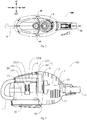
- the handheld vacuum cleaner 100 according to a first specific embodiment of the present disclosure will be illustrated with reference to Figs. 1 and 2 .
- the handheld vacuum cleaner 100 includes the housing 1, the dust cup and the electric motor 3.
- the air inlet 11 is disposed at a front end of the housing 1 and approximately located in the central of the housing 1; the dust cup is disposed at a rear end of the housing 1; the electric motor 3 is disposed inside the housing 1 and located between the air inlet 11 and the dust cup.
- the direction "front” may be construed as the direction away from the human body when the handheld vacuum cleaner 100 is located at the front side of the human body during its practical use, and the opposite direction is defined to be "rear", i.e. the direction facing the human body when the handheld vacuum cleaner 100 is located at the front side of the human body during its practical use.
- the electric motor 3 may be disposed obliquely. With reference to Fig. 1 and in combination with Fig. 2 , a central axis of the electric motor 3 forms an acute angle respectively with the horizontal plane and the vertical plane, and the electric motor 3 may obliquely extend downwards towards the air inlet 11 (e.g. a rear-to-front direction in Fig. 1 ) along the flow direction of the airstream, but is not limited to this. For example, in the flowing direction of the streams and the direction of facing the air inlet 11, the electric motor 3 may obliquely extend upwards towards the air inlet 11 (not shown) along the flow direction of the airstream. Therefore, the occupation space of the electric motor 3 in the housing 1 is reduced by disposing it obliquely, so as to reduce the overall size of the handheld vacuum cleaner 100.
- a communicating channel is provided between the air inlet 11 and the dust cup, and includes at least one of a first sub-channel 41, a second sub-channel 42 and a third sub-channel 43. That is to say, the communicating channel may merely include any one of the first sub-channel 41, the second sub-channel 42 and the third sub-channel 43, or include simultaneously any two of the first sub-channel 41, the second sub-channel 42 and the third sub-channel 43, or include simultaneously the three of the first sub-channel 41, the second sub-channel 42 and the third sub-channel 43.
- the first sub-channel 41 is disposed at at least one of two sides of the dust cup
- the second sub-channel 42 is disposed above the dust cup
- the third sub-channel 43 is disposed below the dust cup.
- the communicating channel includes the first sub-channel 41, and two first sub-channels 41 are provided and located at the two sides of the dust cup separately.
- the communicating channel only includes two first sub-channels 41, both of which extend in the front-and-rear direction and are located on the left and right sides of the dust cup separately, and preferably they are symmetrical with respect to a central vertical plane of the housing 1 extending in the front-and-rear direction.
- the dusty airstreams from the air inlet 11 may flow rearwards from the left side and the right side of the dust cup into the dust cup respectively via the two first sub-channels 41.
- the dust cup includes a body 21, a cyclone drum 22 and a filter 23.
- the body 21 is provided with an inlet and an outlet and includes a cup body 211 and a cup lid 212.
- the top of the cup body 211 is open, and the inlet is formed in a sidewall of the cup body 211.
- the cup lid 212 is disposed at the top of the cup body 211, and the outlet is formed in the cup lid 212.
- the dusty airstreams from the air inlet 11 may enter the cup body 211 via the inlet, and the filtered air may be exhausted from the outlet to the outside of the cup body 211.
- the cyclone drum 22 is disposed inside the body 21 and provided with a cyclone drum inlet 221 communicating with the inlet, and has an open upper end.
- the filter 23 includes a connection portion 231 and a filtration portion 232, in which the connection portion 231 is substantially formed as a flat plate and the connection portion 231 is connected inside the body 21.
- an outer circumferential wall of the connection portion 231 may be connected to an inner circumferential wall of the cup body 211, in which case the filter 23 is mounted inside the cup body 211 via the connection portion 231.
- An opening 2311 is provided in the center of the connection portion 231 and perforates in the thickness direction of the connection portion 231 (e.g. the up-and-down direction in Fig. 1 ).
- connection portion 231 A lower surface of the connection portion 231 is spaced apart from an upper end surface of the cyclone drum 22, and at this moment the connection portion 231 is not in touch with the cyclone drum 22.
- the filtration portion 232 has a substantially hollow tubular structure, in which a first end of the filtration portion 232 (e.g. an upper end in Fig. 1 ) is connected to the connection portion 231 and communicated with the outlet, i.e. the first end of the filtration portion 232 is communicated with the opening 2311 of the connection portion 231, and a second end (e.g. a lower end in Fig. 1 ) thereof extends into the cyclone drum 22.
- the filtration portion 232 is provided with at least one communication hole 2321 communicated with the interior of the cyclone drum 22.
- the dusty airstreams from the inlet may enter the cyclone drum 22 via the cyclone drum inlet 221; air and dust of the dusty airstreams may be separated in the cyclone drum 22; and the dust separated out will be gathered by the cup body 211, so as to achieve the purpose of dust collection and filtration.
- the filtered air flows through the communication hole 2321 of the filtration portion 232 and the opening 2311 of the connection portion 231 successively, and is exhausted from the outlet eventually.
- the impurities having a light weight and a large volume, such as tissues may also be separated out by the cyclone drum 22 and enter into the cup body 211, which can avoid blocking up the filter 23 effectively and make the filter 23 keep clean to improve performance of the filter 23, so as to reduce failure rate of the handheld vacuum cleaner 100 and facilitate use and maintenance thereof.
- the communication hole 2321 is formed in a sidewall of the filtration portion 232. Therefore, the filtered air may enter the filtration portion 232 via the communication hole 2321. Further, a plurality of the communication holes 2321 provided in the sidewall of the filtration portion 232 and spaced apart from one another other. Preferably, the plurality of communication holes 2321 are evenly spaced and distributed in the sidewall of the filtration portion 232.
- the communication hole 2321 may be a circular hole that is simple to process at a low cost, and certainly, the communication hole 2321 also may be an oval hole, an oblong hole or a polygonal hole, etc. It can be understood that the number, the specific shape, the size of the communication hole 2321 and its arrangement in the filtration portion 232 may be determined according to the actual requirements, to make sure a better filtration effect.
- the lower end of the filtration portion 232 extends downwards to a bottom wall of the cyclone drum 22 and is fixed to the bottom wall of the cyclone drum 22.
- the bottom wall of the cyclone drum 22 is provided with a connecting hole perforating in the thickness direction of the bottom wall (e.g. the up-and-down direction in Fig. 1 ), and the lower end of the filtration portion 232 may pass through the connecting hole. Therefore, the filtration portion 232 may be mounted inside the cup body 211 more firmly.
- the handheld vacuum cleaner includes a filter 6 that is disposed between the cup body and the cup lid 212 and located at the downstream of the filter 23. Therefore, the airstreams separated by the cyclone drum 22 may be further filtered by the filter 6 before flowing to the electric motor 3, thus further guaranteeing the normal use of the electric motor 3.
- the "downstream” may be understood as downstream of the flow direction of the airstream.
- the filter 6 is filter cotton, but not limited to this.
- an electric motor air hood 5 is provided between the dust cup and the electric motor 3 and connected between the outlet of the dust cup and the air inlet end 31 of the electric motor 3.
- the electric motor air hood 5 may be constructed to have a sectional area increasing gradually in the flow direction of the airstreams. Therefore, the airstreams filtered by the dust cup may be directed to the electric motor 3 better.
- the dust cup may be detachably mounted to the housing 1. Since the dust cup is located in the rear of the housing 1, it is convenient to mount and remove the dust cup. Further, the dust cup is provided with a handle 7 that is disposed on the side of the dust cup away from the air outlet 11 (e.g. the rear side in Fig. 1 ), and simultaneously the handle 7 is disposed on the side of dust cup away from the electric motor 3. In such a case, the handle 7 is relatively remote from the electric motor 3, thus reducing vibration of the handle 7 and improving the sense of touch during use.
- the handle 7 and the dust cup may be integrally formed, and hence the handle 7 and the dust cup are integrally processed and manufactured, such that the handle 7 is a part of the dust cup. Therefore, users can remove the dust cup by holding the handle 7, resuting in convenient assembling or disassembling and simple processing, thus reducing the cost.
- the air outlet 12 is disposed close to the electric motor 3, such that the airstreams flowing through the electric motor 3 may be exhausted from the air outlet 12 directly.
- the air outlet 12 is relatively remote from the human body, it improves the comfort of using the handheld vacuum cleaner.
- the air outlet 12 is substantially disposed in the front of the housing 1, and may be provided with an air outlet cover 121 that is provided with at least one air hole. Therefore, by disposing the outlet cover 121, it is possible to guarantee the safety of users effectively at the same time of ensuring the air exhaust effect.
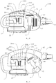
- the handheld vacuum cleaner 100 according to a second specific embodiment of the present disclosure will be illustrated with reference to Fig. 3 .
- the electric motor 3 is disposed horizontally.
- the central axis of the electric motor 3 extends in the front-and-rear direction, and the angle between the central axis of the electric motor 3 and the horizontal plane is zero degree. Therefore, it is convenient to assemble the electric motor 3 with a high efficiency.
- the electric motor air hood 5 has a substantially inverted "L" shape and a sectional area substantially keeping constant in the flow direction of the airstreams.
- the handheld vacuum cleaner 100 according to a third specific embodiment of the present disclosure will be illustrated with reference to Fig. 4 .
- the electric motor is disposed vertically.
- the central axis of the electric motor 3 extends in the up-and-down direction, and the angle between the central axis of the electric motor 3 and the vertical plane is zero degree. Therefore, it is convenient to assemble the electric motor 3 with a high efficiency.
- the electric motor air hood 5 obliquely extends downwards towards the air inlet 11 in the flow direction of airstreams.
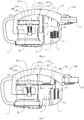
- the handheld vacuum cleaner 100 according to a fourth specific embodiment of the present disclosure will be illustrated with reference to Fig. 5 .
- the communicating channel only includes the second sub-channel 42, and the second sub-channel 42 is disposed at the upper part of the dust cup and forms an arc shape projecting upwards.
- the dusty airstreams entering from the air inlet 11 may flow rearwards from the upper part of the dust cup into the dust cup via the second sub-channel 42.
- the air inlet 11 is disposed in the upper part of the housing 1.
- the electric motor 3 is disposed obliquely.
- the handheld vacuum cleaner 100 according to a fifth specific embodiment of the present disclosure will be illustrated with reference to Fig. 6 .
- the only difference between this embodiment and the fourth specific embodiment is that the electric motor 3 is disposed horizontally.
- Other structures (e.g. the dust cup) of the handheld vacuum cleaner 100 according to this embodiment may be identical to those of the handheld vacuum cleaner 100 according to the first and fourth specific embodiments, which will not be described in detail.
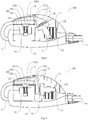
- the handheld vacuum cleaner 100 according to a sixth specific embodiment of the present disclosure will be illustrated with reference to Fig. 7 .
- the only difference between this embodiment and the fourth specific embodiment is that the electric motor 3 is disposed vertically.
- Other structures (e.g. the dust cup) of the handheld vacuum cleaner 100 according to this embodiment may be identical to those of the handheld vacuum cleaner 100 according to the first and fourth specific embodiments, which will not be described in detail.
- the handheld vacuum cleaner 100 according to a seventh specific embodiment of the present disclosure will be illustrated with reference to Fig. 8 .
- the communicating channel only includes the third sub-channel 43, and the third sub-channel 43 is disposed at the lower part of the dust cup and substantially extends in the horizontal direction.
- the dusty airstreams entering from the air inlet 11 may flow rearwards from the lower part of the dust cup into the dust cup via the third sub-channel 43.
- the air inlet 11 is disposed in the lower part of the housing 1.
- the electric motor 3 is disposed obliquely.
- the only difference between this embodiment and the seventh specific embodiment is that the electric motor 3 is disposed horizontally.
- Other structures (e.g. the dust cup) of the handheld vacuum cleaner 100 according to the present embodiment may be identical to those of the handheld vacuum cleaner 100 according to the first and seventh specific embodiments, which will not be described in detail.
- the handheld vacuum cleaner 100 according to a ninth specific embodiment of the present disclosure will be illustrated with reference to Fig. 10 .
- the only difference between this embodiment and the seventh specific embodiment is that the electric motor 3 is disposed vertically.
- Other structures (e.g. the dust cup) of the handheld vacuum cleaner 100 according to this embodiment may be identical to those of the handheld vacuum cleaner 100 according to the first and seventh specific embodiments, which they will not be described in detail.
- the handheld vacuum cleaner 100 improves the structure diversity of the handheld vacuum cleaner 100.
- the electric motor 3 is provided between the air inlet 11 and the dust cup and located remote from the handle 7 of the handheld vacuum cleaner 100, such that only slight vibration is delivered to the handle 7 when the handheld vacuum cleaner 100 is working, which improves the sense of touch of the handheld vacuum cleaner 100.
- the air outlet 12 is relatively remote from the human body, the comfort during use is enhanced. Additionally, it is convenient to assemble and disassemble the dust cup by disposing it in the rear of the housing 1.
Landscapes
- Engineering & Computer Science (AREA)
- Mechanical Engineering (AREA)
- Filters For Electric Vacuum Cleaners (AREA)
Claims (15)
- Handstaubsauger (100), umfassend:ein Gehäuse (1), das mit einem Lufteinlass (11) und einem Luftauslass (12) versehen ist;ein im Gehäuse (1) angeordneter Staubbecher; undein Elektromotor (3), der zwischen dem Lufteinlass (11) und dem Staubbecher angeordnet ist, wobei ein staubiger Luftstrom, der vom Lufteinlass (11) in das Gehäuse (1) eintritt, nacheinander durch den Staubbecher und den Elektromotor (3) strömt und aus dem Luftauslass (12) ausgeblasen wird; undein Kommunikationskanal zwischen dem Lufteinlass (11) und dem Staubbecher vorgesehen ist, dadurch gekennzeichnet, dass der Kommunikationskanal zwei erste Unterkanäle (41) umfasst, die jeweils an den zwei Seiten des Staubbechers vorgesehen und angeordnet sind.
- Handstaubsauger (100) gemäß Anspruch 1, wobei der Elektromotor (3) schräg angeordnet ist.
- Handstaubsauger (100) gemäß Anspruch 2, wobei sich der Elektromotor (3) schräg nach unten zum Lufteinlass (11) entlang einer Strömungsrichtung des Luftstroms erstreckt.
- Handstaubsauger (100) gemäß einem der Ansprüche 1 bis 3, der Elektromotor (3) ist horizontal angeordnet.
- Handstaubsauger (100) gemäß einem der Ansprüche 1 bis 4, der Elektromotor (3) ist vertikal angeordnet.
- Handstaubsauger (100) gemäß einem der Ansprüche 1 bis 5, wobei eine Elektromotor-Lufthaube (5) zwischen dem Staubbecher und dem Elektromotor (3) vorgesehen ist.
- Handstaubsauger (100) gemäß einem der Ansprüche 1 bis 6, wobei der Staubbecher Folgendes umfasst:einen Körper (21), der mit einem Einlass und einem Auslass versehen ist;eine Zyklontrommel (22), die innerhalb des Körpers (21) angeordnet ist und mit einem Zyklontrommeleinlass (221) versehen ist, der mit dem Einlass in Verbindung steht, wobei ein oberes Ende der Zyklontrommel (22) offen ist; undein Filter (23) umfassend einen Verbindungsbereich (231) und einen Filtrationsbereich (232), wobei der Verbindungsbereich (231) innerhalb des Körpers (21) verbunden ist und eine Unterseite aufweist, die von einer oberen Endfläche der Zyklontrommel beabstandet ist, und der Filtrationsbereich (232) ein erstes Ende aufweist, das mit dem Verbindungsbereich (231) verbunden ist und mit dem Auslass und einem zweiten Ende, das sich in die Zyklontrommel (22) erstreckt, verbunden ist, und mit mindestens einem Verbindungsloch (2321) versehen ist, das mit dem Inneren der Zyklontrommel (22) verbunden ist, wobei sich ein unteres Ende des Filtrationsbereichs (232) bevorzugt nach unten zu einer Bodenwand der Zyklontrommel (22) erstreckt und bevorzugt an der Bodenwand der Zyklontrommel befestigt ist.
- Handstaubsauger (100) gemäß Anspruch 7, wobei das Verbindungsloch (2321) in einer Seitenwand des Filtrationsbereichs (232) ausgebildet ist.
- Handstaubsauger (100) gemäß einem der Ansprüche 7 bis 8, wobei der Körper (21) Folgendes umfasst:einen Becherkörper (211) aufweisend eine offene Oberseite, wobei der Einlass in einer Seitenwand des Becherkörpers (211) ausgebildet ist; undeinen Becherdeckel, der an der Oberseite des Becherkörpers (211) angeordnet ist, wobei der Auslass im Becherdeckel (212) ausgebildet ist, der Körper (21) bevorzugt ferner einen Filter (23) umfasst, der zwischen dem Becherkörper (211) und dem Becherdeckel (212) angeordnet ist, wobei der Filter (23) bevorzugt Filterbaumwolle ist.
- Handstaubsauger (100) gemäß einem der Ansprüche 1 bis 9, wobei der Staubbecher abnehmbar mit dem Gehäuse (1) verbunden ist.
- Handstaubsauger (100) gemäß einem der Ansprüche 1 bis 10, wobei der Staubbecher mit einem Griff (7) versehen ist.
- Handstaubsauger (100) gemäß Anspruch 11, wobei der Griff (7) auf einer vom Luftauslass (12) entfernten Seite des Staubbechers angeordnet ist.
- Handstaubsauger (100) gemäß Anspruch 11, der Griff (7) und der Staubbecher sind einstückig ausgebildet.
- Handstaubsauger (100) gemäß einem der Ansprüche 1 bis 13, wobei der Luftauslass (12) neben dem Elektromotor (3) angeordnet ist.
- Handstaubsauger (100) gemäß einem der Ansprüche 1 bis 14, wobei der Luftauslass (12) mit einer Luftauslassabdeckung (121) versehen ist und die Luftauslassabdeckung (121) mit mindestens einem Luftloch versehen ist.
Applications Claiming Priority (3)
| Application Number | Priority Date | Filing Date | Title |
|---|---|---|---|
| CN201620006101.4U CN205458415U (zh) | 2016-01-04 | 2016-01-04 | 手持式吸尘器 |
| CN201610003757.5A CN105640426B (zh) | 2016-01-04 | 2016-01-04 | 手持式吸尘器 |
| PCT/CN2016/076710 WO2017117868A1 (zh) | 2016-01-04 | 2016-03-18 | 手持式吸尘器 |
Publications (3)
| Publication Number | Publication Date |
|---|---|
| EP3400860A1 EP3400860A1 (de) | 2018-11-14 |
| EP3400860A4 EP3400860A4 (de) | 2019-08-07 |
| EP3400860B1 true EP3400860B1 (de) | 2021-03-17 |
Family
ID=59235151
Family Applications (1)
| Application Number | Title | Priority Date | Filing Date |
|---|---|---|---|
| EP16874093.4A Active EP3400860B1 (de) | 2016-01-04 | 2016-03-18 | Tragbarer staubabscheider |
Country Status (4)
| Country | Link |
|---|---|
| US (1) | US9993125B2 (de) |
| EP (1) | EP3400860B1 (de) |
| CA (1) | CA2932594A1 (de) |
| WO (1) | WO2017117868A1 (de) |
Families Citing this family (27)
| Publication number | Priority date | Publication date | Assignee | Title |
|---|---|---|---|---|
| US10258208B2 (en) | 2016-04-11 | 2019-04-16 | Omachron Intellectual Property Inc. | Surface cleaning apparatus |
| US10722086B2 (en) | 2017-07-06 | 2020-07-28 | Omachron Intellectual Property Inc. | Handheld surface cleaning apparatus |
| US9314139B2 (en) * | 2014-07-18 | 2016-04-19 | Omachron Intellectual Property Inc. | Portable surface cleaning apparatus |
| US10791889B2 (en) | 2016-01-08 | 2020-10-06 | Omachron Intellectual Property Inc. | Hand carryable surface cleaning apparatus |
| US10238249B2 (en) * | 2016-01-08 | 2019-03-26 | Omachron Intellectual Property Inc. | Hand carryable surface cleaning apparatus |
| US10646806B2 (en) * | 2016-03-31 | 2020-05-12 | Lg Electronics Inc. | Cleaner |
| US11241129B2 (en) | 2016-04-11 | 2022-02-08 | Omachron Intellectual Property Inc. | Surface cleaning apparatus |
| US10016104B2 (en) | 2016-04-11 | 2018-07-10 | Omachron Intellectual Property Inc. | Surface cleaning apparatus |
| US9986880B2 (en) * | 2016-04-11 | 2018-06-05 | Omachron Intellectual Property Inc. | Surface cleaning apparatus |
| US10016105B2 (en) | 2016-04-11 | 2018-07-10 | Omachron Intellectual Property Inc. | Surface cleaning apparatus |
| US10568477B2 (en) | 2016-04-11 | 2020-02-25 | Omachron Intellectual Property Inc. | Surface cleaning apparatus |
| US10750913B2 (en) | 2017-07-06 | 2020-08-25 | Omachron Intellectual Property Inc. | Handheld surface cleaning apparatus |
| US10506904B2 (en) | 2017-07-06 | 2019-12-17 | Omachron Intellectual Property Inc. | Handheld surface cleaning apparatus |
| US10537216B2 (en) | 2017-07-06 | 2020-01-21 | Omachron Intellectual Property Inc. | Handheld surface cleaning apparatus |
| US10631693B2 (en) | 2017-07-06 | 2020-04-28 | Omachron Intellectual Property Inc. | Handheld surface cleaning apparatus |
| US10702113B2 (en) | 2017-07-06 | 2020-07-07 | Omachron Intellectual Property Inc. | Handheld surface cleaning apparatus |
| US10842330B2 (en) | 2017-07-06 | 2020-11-24 | Omachron Intellectual Property Inc. | Handheld surface cleaning apparatus |
| GB2581647B (en) | 2017-09-22 | 2022-09-14 | Sharkninja Operating Llc | Hand-held surface cleaning device |
| CN112401745A (zh) * | 2019-08-21 | 2021-02-26 | 苏州宝时得电动工具有限公司 | 吸尘器 |
| CN112545359B (zh) * | 2019-09-10 | 2024-05-28 | 苏州市春菊电器有限公司 | 一种便于拆装的尘杯与枪式吸尘器主体的连接结构 |
| CN111001252B (zh) * | 2019-12-23 | 2024-12-24 | 北京小狗吸尘器集团股份有限公司 | 一种过滤组件及集尘杯体 |
| CN115140208A (zh) * | 2021-03-30 | 2022-10-04 | 京东科技信息技术有限公司 | 机器人 |
| CN113287967B (zh) * | 2021-04-12 | 2022-07-12 | 添可智能科技有限公司 | 一种清洁设备 |
| CN113729557B (zh) * | 2021-09-29 | 2024-05-28 | 苏州市春菊电器有限公司 | 一种清理吸尘器尘杯旋风锥缠绕毛发的结构 |
| CN116982878A (zh) * | 2022-06-27 | 2023-11-03 | 苏州意达产品设计有限公司 | 一种基于轴向转切线进风方式的尘杯 |
| US12532999B2 (en) | 2022-07-13 | 2026-01-27 | Jeanie Toler | Solar-powered vacuum device |
| USD1093781S1 (en) * | 2023-09-27 | 2025-09-16 | Zhejiang Prulde Electric Appliance Co., Ltd. | Vacuum cleaner |
Family Cites Families (6)
| Publication number | Priority date | Publication date | Assignee | Title |
|---|---|---|---|---|
| US3758914A (en) * | 1971-10-06 | 1973-09-18 | Whirlpool Co | Vacuum cleaner with movable handle structure |
| US20060156508A1 (en) * | 2005-01-14 | 2006-07-20 | Royal Appliance Mfg. Co. | Vacuum cleaner with cyclonic separating dirt cup and dirt cup door |
| CN1951278A (zh) * | 2005-10-17 | 2007-04-25 | 乐金电子(天津)电器有限公司 | 真空吸尘器 |
| CN201414751Y (zh) * | 2009-06-10 | 2010-03-03 | 宁波锦隆电器有限公司 | 手持式吸尘器 |
| CN103784081B (zh) * | 2014-01-27 | 2017-02-08 | 科沃斯机器人股份有限公司 | 手持式吸尘器 |
| CN204909302U (zh) * | 2015-07-30 | 2015-12-30 | 江苏美的清洁电器股份有限公司 | 电机罩结构和吸尘器 |
-
2016
- 2016-03-18 EP EP16874093.4A patent/EP3400860B1/de active Active
- 2016-03-18 WO PCT/CN2016/076710 patent/WO2017117868A1/zh not_active Ceased
- 2016-06-09 US US15/178,492 patent/US9993125B2/en active Active
- 2016-06-09 CA CA2932594A patent/CA2932594A1/en not_active Abandoned
Non-Patent Citations (1)
| Title |
|---|
| None * |
Also Published As
| Publication number | Publication date |
|---|---|
| US9993125B2 (en) | 2018-06-12 |
| WO2017117868A1 (zh) | 2017-07-13 |
| US20170188763A1 (en) | 2017-07-06 |
| EP3400860A1 (de) | 2018-11-14 |
| CA2932594A1 (en) | 2017-07-04 |
| EP3400860A4 (de) | 2019-08-07 |
Similar Documents
| Publication | Publication Date | Title |
|---|---|---|
| EP3400860B1 (de) | Tragbarer staubabscheider | |
| KR101562262B1 (ko) | 진공 청소기용 청소기 헤드 | |
| CA2791575C (en) | A motor, fan and dirt separation means arrangement | |
| CN109730581B (zh) | 手持吸尘器 | |
| EP3209175B1 (de) | Handstaubsauger | |
| CN105725913A (zh) | 手持式吸尘器 | |
| CN110944555B (zh) | 表面清洁设备 | |
| CN216854552U (zh) | 一种手持式吸尘器主机结构及吸尘器 | |
| CN206063055U (zh) | 手持式吸尘器 | |
| CN211459996U (zh) | 手持式吸尘器 | |
| WO2012032721A1 (ja) | 電気掃除機 | |
| CN105640426B (zh) | 手持式吸尘器 | |
| CN205458413U (zh) | 手持式吸尘器 | |
| CN209951155U (zh) | 手持吸尘器 | |
| CN210931137U (zh) | 手持吸尘器 | |
| CN205458415U (zh) | 手持式吸尘器 | |
| CN112617655A (zh) | 手持吸尘器 | |
| CN211022448U (zh) | 除螨吸尘附件及手持式除螨吸尘设备 | |
| CN205458414U (zh) | 手持式吸尘器 | |
| CN205625802U (zh) | 手持式吸尘器 | |
| CN107212809B (zh) | 垃圾桶式吸尘器 | |
| CN102233532A (zh) | 磨砂机 | |
| CN223585866U (zh) | 吸尘装置及清洁设备 | |
| JP2000083869A (ja) | 電気掃除機 | |
| JP2008188422A (ja) | 空気清浄機能付き電気掃除機 |
Legal Events
| Date | Code | Title | Description |
|---|---|---|---|
| STAA | Information on the status of an ep patent application or granted ep patent |
Free format text: STATUS: UNKNOWN |
|
| STAA | Information on the status of an ep patent application or granted ep patent |
Free format text: STATUS: THE INTERNATIONAL PUBLICATION HAS BEEN MADE |
|
| PUAI | Public reference made under article 153(3) epc to a published international application that has entered the european phase |
Free format text: ORIGINAL CODE: 0009012 |
|
| STAA | Information on the status of an ep patent application or granted ep patent |
Free format text: STATUS: REQUEST FOR EXAMINATION WAS MADE |
|
| 17P | Request for examination filed |
Effective date: 20170620 |
|
| AK | Designated contracting states |
Kind code of ref document: A1 Designated state(s): AL AT BE BG CH CY CZ DE DK EE ES FI FR GB GR HR HU IE IS IT LI LT LU LV MC MK MT NL NO PL PT RO RS SE SI SK SM TR |
|
| AX | Request for extension of the european patent |
Extension state: BA ME |
|
| DAV | Request for validation of the european patent (deleted) | ||
| DAX | Request for extension of the european patent (deleted) | ||
| A4 | Supplementary search report drawn up and despatched |
Effective date: 20190705 |
|
| RIC1 | Information provided on ipc code assigned before grant |
Ipc: A47L 5/24 20060101AFI20190701BHEP Ipc: A47L 9/28 20060101ALI20190701BHEP |
|
| STAA | Information on the status of an ep patent application or granted ep patent |
Free format text: STATUS: EXAMINATION IS IN PROGRESS |
|
| 17Q | First examination report despatched |
Effective date: 20190927 |
|
| GRAP | Despatch of communication of intention to grant a patent |
Free format text: ORIGINAL CODE: EPIDOSNIGR1 |
|
| STAA | Information on the status of an ep patent application or granted ep patent |
Free format text: STATUS: GRANT OF PATENT IS INTENDED |
|
| INTG | Intention to grant announced |
Effective date: 20201222 |
|
| GRAS | Grant fee paid |
Free format text: ORIGINAL CODE: EPIDOSNIGR3 |
|
| GRAA | (expected) grant |
Free format text: ORIGINAL CODE: 0009210 |
|
| STAA | Information on the status of an ep patent application or granted ep patent |
Free format text: STATUS: THE PATENT HAS BEEN GRANTED |
|
| AK | Designated contracting states |
Kind code of ref document: B1 Designated state(s): AL AT BE BG CH CY CZ DE DK EE ES FI FR GB GR HR HU IE IS IT LI LT LU LV MC MK MT NL NO PL PT RO RS SE SI SK SM TR |
|
| REG | Reference to a national code |
Ref country code: GB Ref legal event code: FG4D |
|
| REG | Reference to a national code |
Ref country code: CH Ref legal event code: EP |
|
| REG | Reference to a national code |
Ref country code: DE Ref legal event code: R096 Ref document number: 602016054622 Country of ref document: DE |
|
| REG | Reference to a national code |
Ref country code: IE Ref legal event code: FG4D |
|
| REG | Reference to a national code |
Ref country code: AT Ref legal event code: REF Ref document number: 1371423 Country of ref document: AT Kind code of ref document: T Effective date: 20210415 |
|
| REG | Reference to a national code |
Ref country code: LT Ref legal event code: MG9D |
|
| PG25 | Lapsed in a contracting state [announced via postgrant information from national office to epo] |
Ref country code: BG Free format text: LAPSE BECAUSE OF FAILURE TO SUBMIT A TRANSLATION OF THE DESCRIPTION OR TO PAY THE FEE WITHIN THE PRESCRIBED TIME-LIMIT Effective date: 20210617 Ref country code: GR Free format text: LAPSE BECAUSE OF FAILURE TO SUBMIT A TRANSLATION OF THE DESCRIPTION OR TO PAY THE FEE WITHIN THE PRESCRIBED TIME-LIMIT Effective date: 20210618 Ref country code: HR Free format text: LAPSE BECAUSE OF FAILURE TO SUBMIT A TRANSLATION OF THE DESCRIPTION OR TO PAY THE FEE WITHIN THE PRESCRIBED TIME-LIMIT Effective date: 20210317 Ref country code: FI Free format text: LAPSE BECAUSE OF FAILURE TO SUBMIT A TRANSLATION OF THE DESCRIPTION OR TO PAY THE FEE WITHIN THE PRESCRIBED TIME-LIMIT Effective date: 20210317 Ref country code: NO Free format text: LAPSE BECAUSE OF FAILURE TO SUBMIT A TRANSLATION OF THE DESCRIPTION OR TO PAY THE FEE WITHIN THE PRESCRIBED TIME-LIMIT Effective date: 20210617 |
|
| REG | Reference to a national code |
Ref country code: AT Ref legal event code: MK05 Ref document number: 1371423 Country of ref document: AT Kind code of ref document: T Effective date: 20210317 |
|
| REG | Reference to a national code |
Ref country code: NL Ref legal event code: MP Effective date: 20210317 |
|
| PG25 | Lapsed in a contracting state [announced via postgrant information from national office to epo] |
Ref country code: SE Free format text: LAPSE BECAUSE OF FAILURE TO SUBMIT A TRANSLATION OF THE DESCRIPTION OR TO PAY THE FEE WITHIN THE PRESCRIBED TIME-LIMIT Effective date: 20210317 Ref country code: LV Free format text: LAPSE BECAUSE OF FAILURE TO SUBMIT A TRANSLATION OF THE DESCRIPTION OR TO PAY THE FEE WITHIN THE PRESCRIBED TIME-LIMIT Effective date: 20210317 Ref country code: RS Free format text: LAPSE BECAUSE OF FAILURE TO SUBMIT A TRANSLATION OF THE DESCRIPTION OR TO PAY THE FEE WITHIN THE PRESCRIBED TIME-LIMIT Effective date: 20210317 |
|
| PG25 | Lapsed in a contracting state [announced via postgrant information from national office to epo] |
Ref country code: NL Free format text: LAPSE BECAUSE OF FAILURE TO SUBMIT A TRANSLATION OF THE DESCRIPTION OR TO PAY THE FEE WITHIN THE PRESCRIBED TIME-LIMIT Effective date: 20210317 |
|
| PG25 | Lapsed in a contracting state [announced via postgrant information from national office to epo] |
Ref country code: SM Free format text: LAPSE BECAUSE OF FAILURE TO SUBMIT A TRANSLATION OF THE DESCRIPTION OR TO PAY THE FEE WITHIN THE PRESCRIBED TIME-LIMIT Effective date: 20210317 Ref country code: AT Free format text: LAPSE BECAUSE OF FAILURE TO SUBMIT A TRANSLATION OF THE DESCRIPTION OR TO PAY THE FEE WITHIN THE PRESCRIBED TIME-LIMIT Effective date: 20210317 Ref country code: EE Free format text: LAPSE BECAUSE OF FAILURE TO SUBMIT A TRANSLATION OF THE DESCRIPTION OR TO PAY THE FEE WITHIN THE PRESCRIBED TIME-LIMIT Effective date: 20210317 Ref country code: CZ Free format text: LAPSE BECAUSE OF FAILURE TO SUBMIT A TRANSLATION OF THE DESCRIPTION OR TO PAY THE FEE WITHIN THE PRESCRIBED TIME-LIMIT Effective date: 20210317 Ref country code: LT Free format text: LAPSE BECAUSE OF FAILURE TO SUBMIT A TRANSLATION OF THE DESCRIPTION OR TO PAY THE FEE WITHIN THE PRESCRIBED TIME-LIMIT Effective date: 20210317 |
|
| REG | Reference to a national code |
Ref country code: CH Ref legal event code: PL |
|
| PG25 | Lapsed in a contracting state [announced via postgrant information from national office to epo] |
Ref country code: IS Free format text: LAPSE BECAUSE OF FAILURE TO SUBMIT A TRANSLATION OF THE DESCRIPTION OR TO PAY THE FEE WITHIN THE PRESCRIBED TIME-LIMIT Effective date: 20210717 Ref country code: PT Free format text: LAPSE BECAUSE OF FAILURE TO SUBMIT A TRANSLATION OF THE DESCRIPTION OR TO PAY THE FEE WITHIN THE PRESCRIBED TIME-LIMIT Effective date: 20210719 Ref country code: PL Free format text: LAPSE BECAUSE OF FAILURE TO SUBMIT A TRANSLATION OF THE DESCRIPTION OR TO PAY THE FEE WITHIN THE PRESCRIBED TIME-LIMIT Effective date: 20210317 Ref country code: RO Free format text: LAPSE BECAUSE OF FAILURE TO SUBMIT A TRANSLATION OF THE DESCRIPTION OR TO PAY THE FEE WITHIN THE PRESCRIBED TIME-LIMIT Effective date: 20210317 Ref country code: SK Free format text: LAPSE BECAUSE OF FAILURE TO SUBMIT A TRANSLATION OF THE DESCRIPTION OR TO PAY THE FEE WITHIN THE PRESCRIBED TIME-LIMIT Effective date: 20210317 |
|
| REG | Reference to a national code |
Ref country code: BE Ref legal event code: MM Effective date: 20210331 |
|
| REG | Reference to a national code |
Ref country code: DE Ref legal event code: R097 Ref document number: 602016054622 Country of ref document: DE |
|
| PLBE | No opposition filed within time limit |
Free format text: ORIGINAL CODE: 0009261 |
|
| STAA | Information on the status of an ep patent application or granted ep patent |
Free format text: STATUS: NO OPPOSITION FILED WITHIN TIME LIMIT |
|
| PG25 | Lapsed in a contracting state [announced via postgrant information from national office to epo] |
Ref country code: MC Free format text: LAPSE BECAUSE OF FAILURE TO SUBMIT A TRANSLATION OF THE DESCRIPTION OR TO PAY THE FEE WITHIN THE PRESCRIBED TIME-LIMIT Effective date: 20210317 Ref country code: LI Free format text: LAPSE BECAUSE OF NON-PAYMENT OF DUE FEES Effective date: 20210331 Ref country code: LU Free format text: LAPSE BECAUSE OF NON-PAYMENT OF DUE FEES Effective date: 20210318 Ref country code: DK Free format text: LAPSE BECAUSE OF FAILURE TO SUBMIT A TRANSLATION OF THE DESCRIPTION OR TO PAY THE FEE WITHIN THE PRESCRIBED TIME-LIMIT Effective date: 20210317 Ref country code: CH Free format text: LAPSE BECAUSE OF NON-PAYMENT OF DUE FEES Effective date: 20210331 Ref country code: AL Free format text: LAPSE BECAUSE OF FAILURE TO SUBMIT A TRANSLATION OF THE DESCRIPTION OR TO PAY THE FEE WITHIN THE PRESCRIBED TIME-LIMIT Effective date: 20210317 Ref country code: IE Free format text: LAPSE BECAUSE OF NON-PAYMENT OF DUE FEES Effective date: 20210318 Ref country code: ES Free format text: LAPSE BECAUSE OF FAILURE TO SUBMIT A TRANSLATION OF THE DESCRIPTION OR TO PAY THE FEE WITHIN THE PRESCRIBED TIME-LIMIT Effective date: 20210317 |
|
| 26N | No opposition filed |
Effective date: 20211220 |
|
| PG25 | Lapsed in a contracting state [announced via postgrant information from national office to epo] |
Ref country code: SI Free format text: LAPSE BECAUSE OF FAILURE TO SUBMIT A TRANSLATION OF THE DESCRIPTION OR TO PAY THE FEE WITHIN THE PRESCRIBED TIME-LIMIT Effective date: 20210317 |
|
| PG25 | Lapsed in a contracting state [announced via postgrant information from national office to epo] |
Ref country code: IT Free format text: LAPSE BECAUSE OF FAILURE TO SUBMIT A TRANSLATION OF THE DESCRIPTION OR TO PAY THE FEE WITHIN THE PRESCRIBED TIME-LIMIT Effective date: 20210317 |
|
| PG25 | Lapsed in a contracting state [announced via postgrant information from national office to epo] |
Ref country code: IS Free format text: LAPSE BECAUSE OF FAILURE TO SUBMIT A TRANSLATION OF THE DESCRIPTION OR TO PAY THE FEE WITHIN THE PRESCRIBED TIME-LIMIT Effective date: 20210717 |
|
| PG25 | Lapsed in a contracting state [announced via postgrant information from national office to epo] |
Ref country code: BE Free format text: LAPSE BECAUSE OF NON-PAYMENT OF DUE FEES Effective date: 20210331 |
|
| PG25 | Lapsed in a contracting state [announced via postgrant information from national office to epo] |
Ref country code: CY Free format text: LAPSE BECAUSE OF FAILURE TO SUBMIT A TRANSLATION OF THE DESCRIPTION OR TO PAY THE FEE WITHIN THE PRESCRIBED TIME-LIMIT Effective date: 20210317 |
|
| P01 | Opt-out of the competence of the unified patent court (upc) registered |
Effective date: 20230526 |
|
| PG25 | Lapsed in a contracting state [announced via postgrant information from national office to epo] |
Ref country code: HU Free format text: LAPSE BECAUSE OF FAILURE TO SUBMIT A TRANSLATION OF THE DESCRIPTION OR TO PAY THE FEE WITHIN THE PRESCRIBED TIME-LIMIT; INVALID AB INITIO Effective date: 20160318 |
|
| PG25 | Lapsed in a contracting state [announced via postgrant information from national office to epo] |
Ref country code: MK Free format text: LAPSE BECAUSE OF FAILURE TO SUBMIT A TRANSLATION OF THE DESCRIPTION OR TO PAY THE FEE WITHIN THE PRESCRIBED TIME-LIMIT Effective date: 20210317 |
|
| PG25 | Lapsed in a contracting state [announced via postgrant information from national office to epo] |
Ref country code: MT Free format text: LAPSE BECAUSE OF FAILURE TO SUBMIT A TRANSLATION OF THE DESCRIPTION OR TO PAY THE FEE WITHIN THE PRESCRIBED TIME-LIMIT Effective date: 20210317 |
|
| PG25 | Lapsed in a contracting state [announced via postgrant information from national office to epo] |
Ref country code: TR Free format text: LAPSE BECAUSE OF FAILURE TO SUBMIT A TRANSLATION OF THE DESCRIPTION OR TO PAY THE FEE WITHIN THE PRESCRIBED TIME-LIMIT Effective date: 20210317 |
|
| PGFP | Annual fee paid to national office [announced via postgrant information from national office to epo] |
Ref country code: GB Payment date: 20260325 Year of fee payment: 11 |
|
| PGFP | Annual fee paid to national office [announced via postgrant information from national office to epo] |
Ref country code: DE Payment date: 20260324 Year of fee payment: 11 |
|
| PGFP | Annual fee paid to national office [announced via postgrant information from national office to epo] |
Ref country code: FR Payment date: 20260330 Year of fee payment: 11 |