EP3401000A1 - Adaptateur et cartouche de filtre à air conçue pour être utilisée avec un tel adaptateur - Google Patents
Adaptateur et cartouche de filtre à air conçue pour être utilisée avec un tel adaptateur Download PDFInfo
- Publication number
- EP3401000A1 EP3401000A1 EP17170112.1A EP17170112A EP3401000A1 EP 3401000 A1 EP3401000 A1 EP 3401000A1 EP 17170112 A EP17170112 A EP 17170112A EP 3401000 A1 EP3401000 A1 EP 3401000A1
- Authority
- EP
- European Patent Office
- Prior art keywords
- cartridge
- adapter
- surface area
- projection
- air filter
- Prior art date
- Legal status (The legal status is an assumption and is not a legal conclusion. Google has not performed a legal analysis and makes no representation as to the accuracy of the status listed.)
- Withdrawn
Links
Images


Classifications
-
- B—PERFORMING OPERATIONS; TRANSPORTING
- B01—PHYSICAL OR CHEMICAL PROCESSES OR APPARATUS IN GENERAL
- B01D—SEPARATION
- B01D46/00—Filters or filtering processes specially modified for separating dispersed particles from gases or vapours
- B01D46/24—Particle separators, e.g. dust precipitators, using rigid hollow filter bodies
- B01D46/2403—Particle separators, e.g. dust precipitators, using rigid hollow filter bodies characterised by the physical shape or structure of the filtering element
- B01D46/2411—Filter cartridges
- B01D46/2414—End caps including additional functions or special forms
-
- B—PERFORMING OPERATIONS; TRANSPORTING
- B01—PHYSICAL OR CHEMICAL PROCESSES OR APPARATUS IN GENERAL
- B01D—SEPARATION
- B01D39/00—Filtering material for liquid or gaseous fluids
- B01D39/14—Other self-supporting filtering material ; Other filtering material
- B01D39/16—Other self-supporting filtering material ; Other filtering material of organic material, e.g. synthetic fibres
- B01D39/1669—Cellular material
- B01D39/1676—Cellular material of synthetic origin
-
- B—PERFORMING OPERATIONS; TRANSPORTING
- B01—PHYSICAL OR CHEMICAL PROCESSES OR APPARATUS IN GENERAL
- B01D—SEPARATION
- B01D46/00—Filters or filtering processes specially modified for separating dispersed particles from gases or vapours
- B01D46/0002—Casings; Housings; Frame constructions
- B01D46/0005—Mounting of filtering elements within casings, housings or frames
-
- B—PERFORMING OPERATIONS; TRANSPORTING
- B01—PHYSICAL OR CHEMICAL PROCESSES OR APPARATUS IN GENERAL
- B01D—SEPARATION
- B01D46/00—Filters or filtering processes specially modified for separating dispersed particles from gases or vapours
- B01D46/0084—Filters or filtering processes specially modified for separating dispersed particles from gases or vapours provided with safety means
- B01D46/009—Identification of filter type or position thereof, e.g. by transponders or bar codes
-
- B—PERFORMING OPERATIONS; TRANSPORTING
- B01—PHYSICAL OR CHEMICAL PROCESSES OR APPARATUS IN GENERAL
- B01D—SEPARATION
- B01D2265/00—Casings, housings or mounting for filters specially adapted for separating dispersed particles from gases or vapours
- B01D2265/02—Non-permanent measures for connecting different parts of the filter
- B01D2265/021—Anti-rotational means
-
- B—PERFORMING OPERATIONS; TRANSPORTING
- B01—PHYSICAL OR CHEMICAL PROCESSES OR APPARATUS IN GENERAL
- B01D—SEPARATION
- B01D2265/00—Casings, housings or mounting for filters specially adapted for separating dispersed particles from gases or vapours
- B01D2265/04—Permanent measures for connecting different parts of the filter, e.g. welding, glueing or moulding
- B01D2265/05—Special adapters for the connection of filters or parts of filters
-
- B—PERFORMING OPERATIONS; TRANSPORTING
- B01—PHYSICAL OR CHEMICAL PROCESSES OR APPARATUS IN GENERAL
- B01D—SEPARATION
- B01D2275/00—Filter media structures for filters specially adapted for separating dispersed particles from gases or vapours
- B01D2275/10—Multiple layers
Definitions
- the present invention relates to an adapter for use in a dedicated coupling system for releasably coupling an air filter cartridge and a housing of a dedicated air filter assembly.
- the present invention also relates to an air filter cartridge being adapted for use with such an adapter.
- the present invention also relates to a coupling system for releasably coupling an air filter cartridge and a housing of a dedicated air filter assembly.
- the present invention also relates to an air filter assembly with a housing and with an air filter cartridge.
- Air filter cartridges and dedicated air filter assemblies with respective housings for receiving such air filter cartridges are well known in the prior art.
- Such air filter assemblies are generally known to be used for filtering dirty air to provide clean air.
- clean air can then be used as avionic air, air plane cabin air, industrial air, intake air for gas turbines or combustion engines of a variety of planes, vehicles and other equipment such as: air planes; trucks; buses; off-road construction equipment; agricultural equipment; generator sets; etc.
- the air filter cartridge can be typically serviced by replacing it with a new air filter cartridge.
- an air filter cartridge comprising: a media pack surrounding an open interior and having first and second, opposite, ends; a first end cap positioned on the first end of the media pack; the first end cap having a central air flow aperture there through; a housing seal on the first end cap; and, a second end cap positioned on the second end of the media pack; the second end cap being a closed end cap; and, the second end cap including a central projection arrangement thereon projecting in a direction away from the first end cap; the projection arrangement being non-circular and including at least one arcuate section; the at least one arcuate section defining a curvature that does not correspond to a segment of a circle surrounding a center of the projection, wherein the projection arrangement comprises a closed, solid, continuous serpentine wall.
- An object of the present invention is to improve known air filter cartridges and dedicated air filter assemblies. It is in particular an object of the present invention to provide an improved air filter cartridge and a dedicated air filter assembly with an improved ability to inhibit, at least reduce the likelihood of, at least make more recognizable, an installation or use of an unapproved or incorrect air filter cartridge in a dedicated air filter assembly.
- an object is defined as being “rotatably coupleable” with another object, it means that the object can be coupled with the other object, but, when being coupled, at least one of the objects can still rotate, preferably about a coupling axis of the coupling, with respect to the other object.
- an object is defined as being “non-rotatably coupleable” with another object, it means that the object can be coupled with the other object, but, when being coupled, the objects cannot rotate any more, in particular about a coupling axis of the coupling, with respect to each other.
- the known air filter cartridges can be improved.
- adapting the air filter cartridge for use with an adapter it is advantageously possible to achieve at least one of the afore-mentioned objects of the present disclosure.
- adapting the air filter cartridge for use with an adapter to provide an improved ability to inhibit, at least reduce the likelihood of, at least make more recognizable, an installation or use of an incorrect air filter cartridge in a dedicated air filter assembly.
- the adapter can also be regarded as serving as an interface between the air filter cartridge and the housing. That means that it is possible to indicate if an air filter cartridge is the correct one or not, because generally an air filter cartridge carrying the correct cartridge-side coupling element will fit into the second surface area and filter housing to create a non-rotatable coupling between cartridge and adapter.
- an adapter between the air filter cartridge and a housing of a dedicated air filter assembly it is advantageously possible to adapt the air filter cartridge to a certain adapter, in particular to adapt an end cap showing a cartridge-side coupling element to a respective non-rotatably coupleable second surface area of the adapter, so that at least one of the afore-mentioned objects is achieved.
- the object can be achieved that an installation of an incorrect air filter cartridge is inhibited, made more difficult, or at least made more readily recognizable compared to the prior art solutions.
- a filter media in the air filter cartridge shall be changed in its filter characteristic, while the outer dimensions of the cartridge are unchanged, and such cartridge shall be identified by a specified design of the cartridge-side coupling element, e.g. on the end cap, of the cartridge, one can simply provide a specific shape of the second surface area on the adapter, which surface is non-rotatably coupleable with the cartridge-side coupling element present on the end cap of the filter cartridge, to make sure that the air filter cartridge with the changed filter characteristic is placed into such air filter assembly comprising such an adapter.
- an adapter for use in a dedicated coupling system for releasably coupling an air filter cartridge and a housing of a dedicated air filter assembly, the adapter having a first surface area being rotatably coupleable with a housing-side coupling element of the coupling system, and a second surface area being non-rotatably coupleable with a cartridge-side coupling element of the coupling system, it is possible for the adapter to rotate with respect to the housing-side coupling element and therefore with respect to the housing in the installed position. This advantageously makes installation much easier since the air filter cartridge does not need to have a certain pre-defined position in the housing when being installed.
- the second surface area comprises a adapter-side three-dimensional structure being non-rotationally coupleable with an at least partially, preferably completely, complementary cartridge-side three-dimensional structure of a surface area of the cartridge-side coupling element.
- the structures on the second surface area of the adapter and of the cartridge-side coupling element must not be completely complementary to provide the desired non-rotatable coupling. It is sufficient to have the desired non-rotatable coupling if the three-dimensional structures fit to each other partly. This can for example already be reached if the three-dimensional structure of the cartridge-side coupling element has 6 pin-like projections positioned on a circle but the three-dimensional structure on the second surface area has 8 correspondingly sized recesses or holes positioned on a circle with the same diameter as the circle defined by the pin-like projections, so that 6 of the 8 recesses or holes can receive the 6 pin-like projections to provide the desired non-rotatable coupling.
- the adapter-side three-dimensional structure is preferably non-rotationally coupleable with the cartridge-side three-dimensional structure of a surface area of the cartridge-side coupling element.
- the cartridge-side three-dimensional structure can be a projection or projection arrangement, and the adapter-side three-dimensional structure can be a recess or groove, or vice versa.
- the projection can project from a remainder of an, preferably closed, end cap of an air filter cartridge, in a direction away from the end cap; for example, if the cartridge is substantially cylindric, in a general direction away from an opposite, preferably open, end cap.
- the general direction of projection is preferably generally axial, for example, substantially in the direction corresponding to the general direction of a central axis of the cartridge if the cartridge is substantially cylindric, and away from an opposite, preferably open, end cap.
- axial in this context, it is not meant that the projection is necessarily precisely parallel to a central axis of the cartridge, if the cartridge is cylindrical. Indeed, it is also possible that the projection is angled from central axis of cartridge somewhat.
- the projection can have an outer surface which can slant inwardly, along a direction of extension from an adjacent region of an end cap; and an inner surface which can slant outwardly along its direction of extension from an adjacent region of an end cap.
- Angles to outer and inner surfaces of projection of the type indicated above, can provide the projection with an axially outermost tip, which can be narrowed somewhat relative to a base region of the projection.
- a somewhat narrow tip facilitates insertion into a corresponding groove formed on an adapter, described above.
- such a tip comprises a rounded surface to facilitate insertion into the corresponding groove of adapter, or vice versa.
- such tip can comprise a, preferably rounded, surface to facilitate a non-rotational coupling between the cartridge-side three-dimensional structure or projection of the coupling system and the adapter-side three-dimensional structure or groove on the adapter of the coupling system, or vice versa.
- such a tip comprises a rounded surface, to provide an auto-alignment when an insertion of projection into the groove of adapter is performed.
- a tip can comprise a rounded surface to provide an auto-alignment when a non-rotational coupling between the cartridge-side three-dimensional structure or projection and the adapter-side three-dimensional structure or groove on the adapter of the coupling system is performed, or vice versa.
- the projection preferably comprises a, preferably continuous, wall.
- continuous in this context, it is preferably meant that there are no gaps in the wall with respect to extension around the perimeter defined by such a wall, for example around a center of the projection.
- such wall is preferably closed, more preferably completely “closed”.
- closed it is meant that the wall preferably includes no apertures therethrough, in its continuous extension.
- such a projection is preferably "solid" throughout; i.e. preferably does not have a hollow interior between outer and inner surfaces, although alternatives are possible.
- the projection arrangement preferably has a minimum largest external dimension thereacross.
- the projection preferably has a serpentine outer surface and preferably has a serpentine inner surface.
- serpentine in connection with the outer surface, it is preferably meant that in extension around a center of the projection, the outer surface does not define a series of straight lines or even a circle, but rather a series of alternating inner and outer curves.
- the serpentine outer surface preferably comprises a plurality of radially outwardly facing convex sections, and a plurality of radially outwardly facing concave sections, preferably alternating with one another.
- radially outwardly facing convex section is preferably meant to refer to a section of surface which curves outwardly; and the reference to “radially outwardly facing concave sections” is preferably meant to refer to a section of surface which curves inwardly.
- radially inwardly facing inner surface is preferably also serpentine, preferably comprising a plurality of radially inwardly facing convex sections and radially inwardly facing concave sections, preferably alternating with respect to one another, as the inner surface extends around center of the projection.
- each concave section of inner surface corresponds with, and more preferably aligns radially with, a convex section of outer surface; and, preferably each convex section of inner surface corresponds with, and more preferably aligns radially with, concave section of outer surface.
- Projection preferably defines, in each of the outer surface and inner surface, n concave sections and n convex sections, n being preferably 2, 4, 6, 8, 10, or 12. Further: (a) preferably a curvature of each convex section of the outer surface is the same as each convex section in inner surface, and, (b) preferably a curvature of each concave section of the outer surface is the same as each concave section in inner surface. The result is a regular "petal" shape to projection.
- petal in this context, it is preferably meant that when viewed in plan view, the projection can be seen to have a plurality of outwardly projecting petals, i.e., curved sections.
- regular in this context, it is preferably meant that each outwardly projecting petal has the same shape as each other outwardly projecting petal.
- Projection preferably comprises a plurality of outward, preferably convex petal, sections and inward, preferably concave, sections, preferably providing for a serpentine extension of projection around a center of the projection.
- each outwardly directed convex section is such as to have a smaller radius of curvature than a hypothetical curvature of such a section if directed on, or positioned on, a circle centered on a center of the projection.
- the width of the groove is shaped in such a way that it is not possible to insert a ring structure into the groove.
- the groove has such curves or a curved or preferably serpentine structure that it is impossible to insert a projection being a ring-like and circular projection.
- a preferred groove only substantially corresponding curved, zig-zag shaped or serpentine structures can be inserted.
- the adapter-side three-dimensional structure is ending at an outer rim of the adapter which outer rim is non-circular, preferably oval, and/or elliptical and/or asymmetrical.
- outer rim is non-circular, preferably oval, and/or elliptical and/or asymmetrical.
- one part of the outer rim can have a smaller radius compared with one or more other parts of the outer rim.
- the outer rim has a smaller outer diameter than the inner rim of the end cap surrounding the projection on the end cap. Then the projection needs to be placed at a predetermined position with respect to this asymmetry of the adapter, for good alignment and fit/coupling. If there is no good alignment, there is no auto-fit/coupling.
- the use of e.g. a cylinder-type protrusion on the end cap would not be able to provide good or auto-alignment and thus no auto-fit.
- the outer rim has a larger outer diameter than the inner rim of the end cap surrounding the projection on the end cap.
- the adapter-side three-dimensional structure is ending at an outer rim of the adapter which outer rim is only slightly non-circular.
- the term "slightly" means just being about 1-5% above a respective production tolerance of the outer rim periphery. More preferably, this outer rim is completely circular.
- the second surface area comprises an at least n-fold rotational symmetric three-dimensional structure, n ⁇ 1, preferably n>1, more preferably n ⁇ 8, being non-rotationally coupleable with an at least partially, preferably completely, complementary cartridge-side three-dimensional structure of the cartridge-side coupling element.
- n ⁇ 1 provide the advantages of the present invention.
- the second surface area comprises at least one recess and/or at least one projection being non-rotationally coupleable with at least one at least partially, preferably completely, complementary projection and/or recess of a surface area of the cartridge-side coupling element.
- the second surface area comprises at least one recess and/or at least one projection being non-rotationally coupleable with at least one at least partially, preferably completely, complementary projection and/or recess of a surface area of the cartridge-side coupling element.
- the second surface area comprises at least one, preferably curved and/or serpentine-like and/or zig-zag shaped and/or continuous, groove, and/or at least one, preferably curved and/or serpentine-like and/or zig-zag shaped and/or continuous, projection being non-rotatably coupleable with at least one at least partially, preferably completely, complementary projection and/or recess of a surface area of the cartridge-side coupling element.
- a groove/projection structure is easy to implement and therefore easy to produce.
- the serpentine-like and in particular the serpentine-like and continuous shape provides a simultaneously reliable and low-wear embodiment of the present invention.
- groove and/or projection on the second surface area are centrosymmetric about a central axis of the second surface, and projection and/or recess of a surface area of the cartridge-side coupling element are centrosymmetric about a central axis of the cartridge-side coupling element.
- Such a centrosymmetric structure is easy to implement and therefore easy to produce.
- the first surface area comprises a, preferably pin-like, projection or a, preferably pin-hole-like, receiver for being rotatably coupleable with a, preferably pin-hole-like, receiver or a, preferably pin-like, projection on the housing-side coupling element.
- a structure is easy to implement and therefore easy to produce.
- the cartridge-side coupling element being mounted on, preferably being integral with, more preferably being, an, preferably closed, end cap of the air filter cartridge.
- the housing-side coupling element is releasably mounted in the housing.
- the adapter can be changed but the adapter can be changed together with the housing-side coupling element for ease of service of the adapter, or even only the housing-side coupling element can be changed if the adapter is still alright but the housing-side coupling element is not or shall be changed separately for other reasons.
- the housing-side coupling element comprises at least one flexible and/or spring-like wire, on which a receiver or a projection is mounted for being rotatably coupleable with a projection or with a receiver on the first surface area of the adapter, and which wire is flexible in a coupling direction of a coupling of the first surface area with the housing-side coupling element and/or of a coupling of the second surface area with the cartridge-side coupling element.
- Such at least one flexible wire an easy way to provide an element which is flexible in a coupling direction of a coupling of the first surface area with the housing-side coupling element and/or of a coupling of the second surface area with the cartridge-side coupling element, to enable an easy coupling of the cartridge with the adapter.
- the housing-side coupling element comprises two wires which are crossing each other substantially in their midpoints. By at least two wires the stability of the housing-side coupling element is enhanced.
- the wires carry the receiver or the projection in an area where the wires are crossing each other.
- the housing-side coupling element carries the receiver or the projection within its most stable and robust area.
- the housing comprises a first fixation element and a second fixation element, so that the housing-side coupling element can be, preferably releasably, fixed in the housing between the first fixation element and the second fixation element.
- the housing-side coupling element can be easily mounted in the housing.
- the housing-side coupling element releasably is fixed in the housing between the first fixation element and the second fixation element, it has the technical effect that housing-side coupling element can be serviced independently.
- An air filter cartridge of the present invention for which air filter cartridge is claimed independent protection, is preferably being adapted for use with an adapter of the present invention, comprises a filter media pack extending between a first end and a second, opposite, end, a, preferably closed, first end cap on the first end of the filter media pack, and a cartridge-side coupling element of a coupling system for releasably coupling the air filter cartridge and a housing of a dedicated air filter assembly, preferably according to the present invention, wherein the cartridge-side coupling element being mounted on, preferably being integral with, more preferably being, the first end cap.
- the air filter cartridge further comprises a second end cap on the second end of the filter media pack, wherein the cartridge-side coupling element comprises a surface area facing away from the second end cap, the surface area having a three-dimensional structure, and wherein a shortest distance between the surface area and the second end of the media pack is, preferably between about 1, about 3, about 5 or about 10 % and about 20, about 25 or about 30%, shorter than the axial length of the filter media pack from its first end to its second end.
- the inventive air filter cartridge is easier to handle and the coupling between the inventive adapter and the cartridge is stronger since the second end cap and its contact with the dedicated housing of the dedicated air filter assembly is closer to the coupling interface, i.e., the contact between the second surface area of the adapter and the three-dimensionally structured surface area of cartridge-side coupling element.
- the adapter is preferably partly positioned inside the first end cap.
- the total overall outer length of such inventive air filter cartridge is reduced which makes it possible to make the filter media pack longer compared to known air filter cartridges where the shortest distance between the surface area of a coupling element and the second end of the media pack is equal or even longer than the length of the filter media pack from the first end to the second end.
- a longest distance between the surface area and the second end of the media pack is, preferably between about 1, about 3, about 5 or about 10 % and about 20, about 25 or about 30%, longer than the axial length of the filter media pack from its first end to its second end.
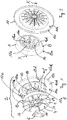
- Figure 1 shows a perspective exploded view on a first embodiment of the present invention.
- Figure 1 shows an adapter 1 for use in a dedicated coupling system 2 for releasably coupling an air filter cartridge, for example an air filter cartridge 20 according to Figure 9 , and a housing of a dedicated air filter assembly, for example an air filter assembly 34 and a housing 36 according to Figures 15 and 16 .
- Adapter 1 comprises a first surface area 4 facing a housing-side coupling element 6 of the coupling system 2, when in use, and being rotatably coupleable with the housing-side coupling element 6, and a second surface area 8 facing a cartridge-side coupling element 10 of the coupling system 2, when in use, and being non-rotatably coupleable with the cartridge-side coupling element 10.
- the cartridge-side coupling element 10 is a closed end cap of an air filter cartridge, for example an air filter cartridge 20 as shown in the second embodiment of figure 9 , described below.
- the first surface area 4 of adapter 1 is rotatably coupleable with the housing-side coupling element 6, by having a pin-like projection 12 insertable in a respective recess in a projection 14 of the housing-side coupling element 6.
- Such recess has a substantially complementary width to be able to receive protection 12.
- Such recess can be shaped as for example the shape of recess 14a a as shown in the embodiment of figure 10 .
- projection 14 as an outer diameter which is smaller than a corresponding recess in projection 12 so that the rotatable coupling between the housing-side coupling element 6 and the first surface area 4 of adapter 1 is provided by having a receiver on the adapter 1 which receives projection 14 for the rotatable coupling connection between the housing-side coupling element 6 and the adapter 1. In both cases adapter 1 can rotate about the housing-side coupling element 6.
- the cartridge-side coupling element 10 is a closed end cap of an air filter cartridge, for example an air filter cartridge 20 as shown in the second embodiment of figure 9 , described below.
- the cartridge-side three-dimensional structure 18 of the surface area 10a of the cartridge-side coupling element 10 is complementary to the recess/groove 16 and is substantially a serpentine-like and continuously shaped projection 18 being substantially complementary shaped to the shape of the recess 16, and a central recess area 18a being complementary to the positive structure or projection 16a on the adapter 1, as can in particular also be seen in Figures 10, 12 and 16 .
- Element 10 has an outer perimeter 10c provided by a ring-like structure being preferably centrosymmetric with the central axis X of the element 10.
- element 10 When moving from the outer perimeter 10c towards the central axis X, element 10 has a substantially flat ring-like part 10d being connected to part 10c.
- Part 10d shows a substantially flat surface being substantially normal to the outer surface of outer perimeter 10c.
- element 10 Further moving towards axis X, element 10 has another ring-like structure 10e being connected to part 10d.
- Structure 10e is substantially normal to part 10d and is substantially parallel to part 10c, and part 10e connects part 10d with a bottom 10f of a ring-like groove-like structure 10f positioned between part 10e and the central ring-like projection 18.
- the central recess area 18a When moving further towards axis X, the central recess area 18a being complementary to the positive structure or projection 16a on the adapter 1, as can in particular also be seen in Figures 10, 12 and 16 , is provided.
- the central recess area 18a being preferably centrosymmetric to projection 18.
- a depth 18b of the central recess 18a, measured parallel to axis X is deeper than the depth of the bottom area 10f, defined by the parallel extension of wall or ring 10e if measured parallel to axis X.
- An intersection of a plane through bottom 10f occurs preferably at substantially the same point of axis X as an intersection of a plane through a bottom 10g of recess 18a.
- element 10 is preferably enhanced by optional additional, preferably 4-32, here preferably 16 ribs 17d positioned, preferably regularly separated, preferably on the inner wall of part 10e, as can be seen best in the examples of Fig. 1 , 6 , 7 , and 12 .
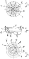
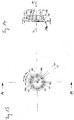
- Figure 2 shows the first embodiment of figure 1 in another exploded respective schematic view, exploded along a central axis X of the structures.
- Fig. 2 shows the second surface area 8 of adapter 1.
- the second surface area 8 is ending at or onto an outer rim 8a.
- the outer rim 8a constitutes the outer perimeter of adapter 1.
- the second surface area 8 comprises a adapter-side three-dimensional structure 16 being non-rotationally coupleable with a complementary cartridge-side three-dimensional structure 18 of the surface area 10a of the cartridge-side coupling element 10 as shown in figure 1 .
- the adapter-side three-dimensional structure 16 on the second surface area 8 of adapter 1 comprises a smooth circular area 8b adjacent to outer rim 8a, and, when moving from the outer rim 8a towards the central axis X, on the opposite end of the smooth circular area 8b, a serpentine-like and continuous recess or groove 16 in the second surface area 8, see also Fig. 4 .
- the smooth area 8b has two main parts, a bigger, outermost, slanted part 8ba being angled about 45 degrees (generally angles between about 25 to about 75 degrees are preferred) with respect to the central axis X, and a smaller, innermost part 8bb of area 8b being substantially normal relative to the central axis X.
- central positive structure or projection 16a which is centrosymmetric about central axis X.
- the position of the three-dimensional structures can be inverted, which means that the position of the projection and of the recess can be interchanged, in particular between adapter and end cap of the filter element.
- Projection 18 fits into groove 16. This is for example clearly visible in the cross-sectional view of the second embodiment in figure 10 .
- the second surface area 8 comprises one recess in the form of the serpentine-like continuous groove 16
- more than one recess is provided in surface area 8.
- more than one projection 18 is provided on surface area 10a of the cartridge-side coupling element 10, and vice versa.
- the cross-sectional shape of the groove 16 is such that it is not possible to insert a ring-like circular structure into such groove 16.
- such groove 16 has such a structure that it is impossible to insert a projection 70 being a ring-like and circular projection into such groove 16.
- a preferred groove 16 only substantially correspondingly shaped structures can be inserted.
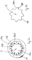
- FIG. 2a shows an example of such groove 16.
- Figure 2a is a schematic plan view on another embodiment second surface area of the adapter 1 of the present invention.
- Groove 16 of Fig. 2a has a cross-sectional shape so that it is impossible to insert a ring-like and circular projection into groove 16.
- This aspect of groove 16 is preferably further emphasized by radially extending ribs 17b which extend radially from the radially outermost parts of the curved and convex parts of the three-dimensional structure 16a in the middle of adapter 1.
- groove 16 only substantially correspondingly shaped structure as for example shown in Fig. 2b can be inserted.
- groove 16 is limited on its side which is opposite to the central area 16a by an outer wall or projecting structure 16d being similar to the outer structure 16d shown in Figs. 2 and 5 .
- wall 16d preferably carries preferably radially extending ribs 17a which extend radially from the radially innermost parts of the curved and convex parts of an inner three-dimensional structure of wall 16d of adapter 1, in direction to the central axis X.
- these ribs 17a and 17b preferably cooperate with each other to preferably inhibit, more preferably completely inhibit, a rotation of the respective projection 18 of Fig. 2c , 2d, and 2e .
- the ribs provide for this inhibition of rotation of projection 18.
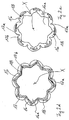
- Figure 2b is a schematic plan view on another embodiment of a cartridge-side coupling element of the coupling system of the present invention, being adapted to the second surface area of the adapter of Fig. 2a .
- the structure shown in Fig. 2b is a serpentine-like projection 18.
- the convex sections 88c of outer surface 88 of projection 18 are curved corresponding to the groove, see also the further detailed description of sections 88c of outer surface 88 of a similar projection 18 further below with respect to Fig. 13-14A .
- Figure 2c is a schematic plan view on an assembled coupling between the cartridge-side coupling element of Fig. 2b with the second surface area of the adapter of Fig. 2a .
- Fig. 2c shows in schematic form the interaction and non-rotatable coupling between the groove 16 of Fig. 2a and the projection 18 of Fig. 2b . It can be seen that projection 18 perfectly fits into groove 16.
- Figure 2d is a schematic plan view on another embodiment of an assembled coupling between a cartridge-side coupling element with the second surface area of the adapter of Fig. 2a .
- Figure 2e is a schematic plan view on another embodiment of an assembled coupling between a cartridge-side coupling element with the second surface area of the adapter of Fig. 2a .
- Figs. 2d and 2e show schematically that it is also possible to change the alternating curved, in particular convex and concave, parts of the serpentine projections 18 as shown in figures 1, 2 , 2b and 2c into sharp edges, e.g. like at least one apex of a triangle.
- Such sharp edges can for example create a, preferably continuous, zig-zag shaped structure as shown in Fig. 2d , in particular a zig-zag shaped wall or projection 18.
- the projection 18 is a continuous zig-zag shaped wall 18, the zig-zag shape when looking at a cross section through such wall as schematically depicted in Fig. 2d .
- By using such a zig-zag shaped projection 18 it is again also possible to insert such a projection 18 into a recess or groove 16 which has a shape so that a ring-like and circular projection cannot be inserted into such recess or groove 16.
- cartridge-side three-dimensional structure and/or the adapter-side three-dimensional structure show(s) both a projection and a recess/groove.
- Fig. 2e shows that the projection 18 and/or the recess can be non-continuous, for example by using only the depicted wall sections for the projection 18, and/or by using only not-shown groove sections for the recess/groove.
- the depicted wall sections can preferably be positioned on a virtual circle. In Fig. 2e the groove 16 is shown continuous.
- the depicted embodiments also shows a central projection 16a being for itself an 8-fold-rotational symmetric adapter-side three-dimensional structure. This structure fits into a respective recess 18a within projection 18 on the surface area 10a of the cartridge-side coupling element 10. It is also sufficient to reach the goals of the present invention to have only projection 16a and recess 18a.
- Figure 3 shows a plan view on the first surface area 4 of adapter 1 of figure 1 .
- ribs 19 and 21 are provided which preferably serve to enhance the structural stability of projections 16d and 16a, respectively, of adapter 1, see also Figs. 1, 2 and 5 .
- Figure 4 shows a side view on adapter 1 of figure 1 .
- Figure 5 shows a plan view on the second surface area 8 of adapter 1 of figures 1 and 2 .
- Figure 6 shows a plan view on the surface area 10a of the cartridge-side coupling element 10 of the coupling system 2 of figure 1 .
- Figure 7 shows a side view on the cartridge-side coupling element 10 of figure 1 .
- adapter-side three-dimensional structure 16 on the second surface area 8 of adapter 1 comprises a smooth circular area adjacent to outer rim 8a.
- the outer rim 8a is asymmetrical in that preferably the radius r1 extending to the topmost part of outer rim 8a shown in Fig. 4 is shorter than the radius r2 extending to the lowest part of outer rim 8a shown in Fig. 4 , see also Figs. 3, 5 , 10 and 12 .
- the surface area 10a has an outer flat or plane part, on the inner side of which it is provided a ring part which steeply, preferably nearly in a right angle, slants down to the bottom 20a (see figure 12 ) of end cap 10.
- a number of, here 16, reinforcement ribs to reinforce the whole end cap 10.
- the reinforcement ribs can preferably be arranged at regular angular intervals.
- Figure 8 shows a plan view on the back side 10b of the cartridge-side coupling element 10 of figures 1 and 2 .
- Figure 9 shows a second embodiment of the present invention in a perspective view. Those parts of the second embodiment of figure 9 which are shown with the same reference numerals as of figure 1-8 are not described here again.
- Air filter cartridge 20 comprises a filter media, e.g. media 40 as shown in Figs. 15 and 16 , positioned between closed end cap 10 and an open end cap 22 located on an end of the cartridge 20 opposite closed end cap 10.
- the filter media 40 is surrounded by a mesh-like outer liner 24 for stabilizing the air filter cartridge 20.
- the depicted air filter cartridge 20 can be installed in a air filter assembly, e.g. the assembly 34 as shown in Figs.
- the air filter cartridge 20 can enter the air filter cartridge 20 through the mesh-like outer liner 24 and is then filtered by the filter media 40 and then enters an interior of the air filter cartridge 20, for example an interior 20a as shown in figures 10 and 12 and 15 and 16 , described below, so that such cleaned air can then exit from the interior 20a of the air filter cartridge 20 through the opening 42 in the open end cap 22 and through the outlet opening 44 of the housing 36 to be used further.
- the inverted air flow direction is also possible, i.e., dirty air flow flowing through opening 42 into interior 20a, then filtered by media 40, then entering an interior 46 of housing 36 and then leaving the housing 36 through opening 44.
- the housing-side coupling element 6 is releasably mountable in a housing, e.g. a housing of figures 15 and 16 , of a dedicated air filter assembly, e.g. an assembly of figures 15 and 16 , by comprising two flexible and spring-like wires 26a and 26b, which wires 26a and 26b are releasably fixable in the housing by hooking ends 28, 30 and 32 of wires 26a and 26b into respective openings in the housing, as e.g. shown in figures 15 and 16 , to releasably fix ends 28, 30, 32 in the respective openings.
- the wires 26a and 26b are flexible in a coupling direction of a coupling of the first surface area 4 with the housing-side coupling element 6 and/or of a coupling of the second surface area 8 with the cartridge-side coupling element 10.
- wires 26a and 26b are crossing each other substantially in their midpoints 26aa and 26bb.
- the air filter cartridge 20 is retained at a central position.
- a receiver in the form of the housing-side coupling element 6 for being rotatably coupleable with the projection 12 on the first surface area 4 on adapter 1.
- Wires 26a and 26b carry the housing-side coupling element 6 in the form of a receiver in the area where they are crossing each other.
- Figure 10 shows a cross sectional view of a part of the second embodiment of figure 9 .
- the interior 20a and the filter media 20b of the air filter cartridge 20 can be seen.
- the adapter 1 comprises an outer rim 8a which is non-circular, preferably oval, more preferably asymmetrical.
- the outer rim 8a can also be elliptical.
- the outer rim 8a is asymmetrical in that preferably the radius r1 extending to the topmost part of outer rim 8a shown in Fig. 4 is shorter than the radius r2 extending to the lowest part of outer rim 8a shown in Fig. 4 .
- the outer rim 8a is circular but its center is off-center which means that the circle center of the outer rim 8a is not located on the center of the adapter-side three-dimensional structure 16 on the surface area 8.
- outer rim 8a has a greater outer diameter than the inner rim 10c (see Figs. 9 and 10 ) surrounding the flower shaped projection 18 on the end cap 10. But at least a part of the outer diameter of the adapter 1 has to fit inside the inner diameter 10c.
- the ribs viewable in Figures 1 , 6 , 7 and 12 can further reduce the inner diameter available for the insertion depth of the adapter 1 into the space inside the end cap 10 down to its bottom 20a.
- the outer rim can be completely circular, the center of the respective circle preferably being off-centre with respect to the center of the end cap.
- the cartridge-side coupling element 10 comprises the three-dimensionally structured surface area 10a facing away from the second end cap 22.
- the shortest distance SD between the three-dimensionally structured surface area 10a and a second end (20b2) of the media pack 20b is, preferably between about 1, about 3, about 5 or about 10 % and about 20, about 25 or about 30%, shorter than the axial length L of the filter media pack 20b, defined between a first end 20b1 and the second end 20b2 of the filter media pack 20b. Therefore, the mass of the air filter cartridge 20 is less spread out over the length of the air filter cartridge 20 but more centered.
- a longest distance LD between the surface area 10a and the second end 20b2 of the filter media pack 20b is, preferably between about 1, about 3, about 5 or about 10 % and about 20, about 25 or about 30%, longer than the length L of the filter media pack 20b, defined between its first end (20b1) and its second end (20b2).
- a part of the cartridge-side three-dimensional structure 18 of the surface area 10a of the cartridge-side coupling element 10 is located axially outside the length of the air filter cartridge 20 if measured between the first end cap 10 and the second end cap 22.
- the cartridge-side three-dimensional structure 18 of the surface area 10a of the cartridge-side coupling element 10 can at least partially, or only partially protrude from the first end cap 10, or from the filter media 20b. But this is preferred, only.
- Projection 18 can be positioned in a axial range along axis X between 50% (or 60 or 70 or 80 or 90) and 130% (or 80 or 90 or 100 or 110 or 120), not excluding other ranges, of the length L of the air filter cartridge 20 defined between the first end cap 10 and the second end cap 22, measured from the second end cap 22 towards the first end cap 10.
- the requirement that projection 18 is "positioned in an axial range along axis X" means that LD is located in that axial range and that the part of back side 10b being nearest to end cap 22 is located in that axial range.
- such axial position of projection 18 is coordinated with the ranges for SD and LD.
- LD is equal or shorter than L so that the whole projection 18 is located within the inner volume 20a defined by the media pack 20b.
- Figure 11 shows a plan view on the second embodiment of figure 9 from the left side of figure 10 .
- Figure 12 shows a partially exploded view of the part of the second embodiment as shown in figure 10 .
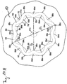
- Fig.13 a fragmentary, schematic outside end view toward the closed end cap 10 of cartridge 20 of Figs. 9-12 is provided.
- the end view of cartridge 20 is taken directed toward end cap 10.
- the structural surface viewable in Fig.13 is a central part of exterior surface area 10a of end cap 10, Figs. 9-12 .
- FIG.14 a fragmentary cross-sectional view is taken along line 14-14, Fig.13 .
- both an exterior surface area 10a and an interior surface area 10b are viewable in end piece 10.
- the depicted central portion of end cap outer surface area 10a includes thereon the cartridge-side three-dimensional structure 18 as a projection arrangement 70.
- the projection arrangement 70 projects from a remainder of end cap 10, in a direction away from the end cap 10; i.e., in a general direction away from opposite end cap 22.
- the distance of projection 70 indicated at dimension CJ, Fig.14 is typically at least 10 mm, usually at least 15 and often within the range of 20 to 40 mm. In the example depicted, the dimension CJ is 25 mm.
- the direction of projection 70 is generally axial, i.e., in the direction corresponding to the general direction of central axis X, and away from end cap 22.
- axial in this context, it is not meant that the projections of outer and inner surfaces 70o, 70i of projection 70 are necessarily precisely parallel to axis X. Indeed each can be angled from axis X somewhat.
- outer surface 70o slants inwardly, along a direction of extension from an adjacent region of end cap 10; and, inner surface 70i slants outwardly along its direction of extension from an adjacent region of end cap 10.
- This angle of slant inwardly of surface 70o is indicated at CK, and is generally within the range of 3-7°; inclusive.
- the corresponding angle of extension outwardly surface 70i is indicated at CM and typically within the range of 3-7°; inclusive.
- Fig.14 CK and CM are each 5.6°.
- Angles to surfaces 70o, 70i of the type indicated, provide the projection 70 with an axially outermost tip 70t, which is narrowed somewhat relative to a base region 70b of projection 70.
- a somewhat narrow tip 70t facilitates insertion into the groove formed between walls 16 and 16a of adapter 8, described above.
- tip 70t is a rounded surface to facilitate insertion into the groove 16 of adapter 8, or with other words: tip 70t comprises a rounded surface to facilitate a non-rotational coupling between the cartridge-side three-dimensional structure 18 or projection 70 and the adapter-side three-dimensional structure or groove 16 on the adapter 8 of the coupling system 2 is performed, or vice versa.
- tip 70t comprises a rounded surface to provide an auto-alignment when an insertion of projection 70 into the groove 16 of adapter 8 is performed, or with other words: tip 70t comprises a rounded surface to provide an auto-alignment when a non-rotational coupling between the cartridge-side three-dimensional structure 18 or projection 70 and the adapter-side three-dimensional structure or groove 16 on the adapter 8 of the coupling system 2 is performed, or vice versa.
- FIG.14A a schematic, fragmentary, plan view of projection arrangement 70 taken in a general direction of arrow 80, Fig.14 . It is noted that in Fig.14A , the schematic depiction provides the general shape of projection 70 in plan view, and does not account for a slant to sides 70o, 70i.
- the particular projection arrangement 70 depicted preferably comprises a continuous wall 84.
- continuous in this context, it is preferably meant that there are no gaps in the wall 84 with respect to extension around the perimeter defined by the wall 84; i.e., around center 27z.
- the wall 84 is preferably completely “closed.” By this it is meant that the wall 84 preferably includes no apertures therethrough, in its continuous extension.
- the projection 70 is preferably "solid" throughout; i.e. preferably does not have a hollow interior between surfaces 70o, 70i, although alternatives are possible.
- the projection arrangement 70 preferably has a minimum largest external dimension thereacross, corresponding to dimension D 1 , Fig.14A of at least 35 mm and more preferably within the range of 40 to 100 mm. A advantage of this is that it facilitates engagement with the access cover 4, in a typical preferred arrangement.
- the particular wall 84 depicted surrounds an open and recessed interior surface section 85.
- This section preferably has a smallest internal dimension access shown at D 2 , of at least 15 mm typically at least 20 mm and more preferably within the range of 30 to 90 mm.
- projection 70 is configured around center 27z such that the minimum largest dimension thereacross indicated at D 1 , can be measured in at least two directions at right angles to one another; i.e., D 1 indicated in Fig.14A would preferably also indicate a minimum largest dimension in a direction perpendicular to line D 1 .
- the configuration of the objection 70 is such that the smallest inside dimension thereacross, indicated at D 2 , is met in two directions, the first direction being for example as indicated at line D 2 , and a second dimension taken perpendicular to the first dimension.
- the projection 70 has a depth of extension from its tip 70t over a distance of at least 6 mm (and preferably at least 12 mm) in which the thickness of projection 70 preferably does not exceed 10 mm, but is more preferably at least 4 mm (discounting tapering at the very tip.) This would be for example a width between walls 70i, 70o, extending inwardly from tip 70t preferably at least a depth of 25% and more preferably at least 35% of its extent of projection. Of course near the base 70b, Fig.14 , projection 70 may thicken (widen) somewhat.
- the particular, closed, continuous wall 84 depicted preferably has a serpentine outer surface 88 and preferably has a serpentine inner surface 89, corresponding to surfaces 70o, 70i respectively.
- serpentine in connection with the outer surface 88, it is meant that extension around center 27z, outer surface 88 does not define a series of straight lines or even a circle, but rather a series of alternating inner and outer curves.
- serpentine surface 88 preferably comprises a plurality of radially outwardly facing convex sections 88c, and a plurality of radially outwardly facing concave sections 88d alternating with one another.
- radially outwardly facing convex section 88c is meant to refer to a section of surface 88 which curves outwardly; and the reference to “radially outwardly facing concave sections 88d” is meant to refer to a section of surface 88 which curves inwardly.
- radially inwardly facing inner surface 89 is preferably also serpentine, comprising a plurality of radially inwardly facing convex sections 89c and radially inwardly facing concave sections 89d, alternating with respect to one another, as the inner surface 89 extends around center 27z.
- each concave section 89d of inner surface 89 corresponds with, and aligns radially with, a convex section 88c of outer surface 88; and, each convex section 89c of inner surface 89 is aligned radially with concave section 89d of outer surface 88.
- wall 84 preferably defines, in each of the outer surface 88 and inner surface 89, eight concave sections and eight convex sections. Further: (a) preferably a curvature of each convex 88c section of surface 88 is the same as each other convex section 88c in surface 88, and, (b) preferably a curvature of each concave section 88c is the same as each other concave 88d. The same is preferably true for each cover section 89c and each concave section 89d. The result is a regular "petal" shape to projection 70.
- petal in this context, it is meant that when viewed in plan view, the projection 70 can be seen to have a plurality of outwardly projecting petals, i.e., curved sections.
- regular in this context, it is meant that each outwardly projecting petal has the same shape as each other outwardly projecting petal.
- each convex section 88c in the outer surface 88 preferably can be seen to define a vertex of an octagonal shape, indicated at phantom lines at 95.
- each center point of each concave section 89c in surface 89 preferably defines a center point in a side of an internally positioned octagon depicted in phantom lines at 96.
- the octagons 95, 96 are preferably radially aligned, one spaced from the other.
- serpentine projection 70 preferably comprises a plurality of outward convex petal sections and inward concave sections, preferably providing for a serpentine extension of wall projection 70 around center 27z.
- each outwardly directed convex section 89c is such as to have a smaller radius of curvature than a hypothetical curvature of such a section if directed on, or positioned on, a circle centered on center 27z. This is apparent by referring to Fig.13 and comparing the curvature of circle C1 to the curvature of outer convex sections 88c.
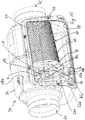
- FIG. 15 shows a further embodiment with an air filter assembly 34 comprising a cartridge 20 of the embodiment of Fig. 9 , and with a housing 36.
- Housing 36 is shown partly open at an aperture 38 which can be closed by a not shown cover, in use.
- Air filter cartridge 20 comprises a filter media 40 positioned between the closed end cap 10 and the open end cap 22 located on an end of the cartridge 20 opposite closed end cap 10.
- the filter media 40 is surrounded by a mesh-like outer liner 24 for stabilizing the air filter cartridge 20.
- Cartridge 20 is installed in the air filter assembly 34 by putting the air filter cartridge 20 in the housing 36 so that the open end cap 22 is in sealing contact with a surrounding of an outlet opening 42 of the housing 36 so that dirty air which enters the housing 36 through an inlet 44 can enter the air filter cartridge 20 through the mesh-like outer liner 24 and is then filtered by the filter media 40 and then enters the interior 20a of the cartridge 20 so that such cleaned air can then exit from the interior 20a through the opening 42 in the open end cap 22 and through the outlet opening 44 of the housing 36 to be used further.
- the inverted air flow direction is also possible, i.e., dirty air flow flowing through opening 42 into interior 20a, then filtered by media 40, then entering an interior 46 of housing 36 and then leaving the housing 36 through opening 44.
- the housing-side coupling element 6 is releasably mountable in the housing 36 by comprising two flexible and spring-like wires 26a and 26b, which wires 26a and 26b are releasably fixable in the housing 36 by hooking ends 28, 30 and 32 of wires 26a and 26b into respective openings 48a, 48b in the housing 36 to releasably fix ends 28, 30, 32 in the respective openings 48a, 48, so that the openings 48a, 48b serve as fixation elements.
- Fig. 16 shows a cross section of the air filter assembly 34 of Fig. 15 comprising the adapter of Figs. 1-8 , and comprising the air filter cartridge 20 of Figs. 9-12 .
Landscapes
- Chemical & Material Sciences (AREA)
- Chemical Kinetics & Catalysis (AREA)
- Physics & Mathematics (AREA)
- Geometry (AREA)
- Respiratory Apparatuses And Protective Means (AREA)
- Filtering Of Dispersed Particles In Gases (AREA)
Priority Applications (7)
| Application Number | Priority Date | Filing Date | Title |
|---|---|---|---|
| EP17170112.1A EP3401000A1 (fr) | 2017-05-09 | 2017-05-09 | Adaptateur et cartouche de filtre à air conçue pour être utilisée avec un tel adaptateur |
| RU2022106734A RU2022106734A (ru) | 2017-05-09 | 2018-05-08 | Переходник и картридж воздушного фильтра, приспособленный для использования с этим переходником |
| EP18724434.8A EP3634602B1 (fr) | 2017-05-09 | 2018-05-08 | Système de couplage pour un filtre à air |
| CN201880029797.4A CN110603085A (zh) | 2017-05-09 | 2018-05-08 | 适配器以及被适配成与这种适配器一起使用的空气过滤器滤芯 |
| US16/611,556 US11504664B2 (en) | 2017-05-09 | 2018-05-08 | Adapter and air filter cartridge being adapted for use with such an adapter |
| PCT/US2018/031656 WO2018208824A1 (fr) | 2017-05-09 | 2018-05-08 | Adaptateur et cartouche de filtre à air conçue pour être utilisée avec un tel adaptateur |
| RU2019135625A RU2769706C2 (ru) | 2017-05-09 | 2018-05-08 | Переходник и картридж воздушного фильтра, приспособленный для использования с этим переходником |
Applications Claiming Priority (1)
| Application Number | Priority Date | Filing Date | Title |
|---|---|---|---|
| EP17170112.1A EP3401000A1 (fr) | 2017-05-09 | 2017-05-09 | Adaptateur et cartouche de filtre à air conçue pour être utilisée avec un tel adaptateur |
Publications (1)
| Publication Number | Publication Date |
|---|---|
| EP3401000A1 true EP3401000A1 (fr) | 2018-11-14 |
Family
ID=58698993
Family Applications (2)
| Application Number | Title | Priority Date | Filing Date |
|---|---|---|---|
| EP17170112.1A Withdrawn EP3401000A1 (fr) | 2017-05-09 | 2017-05-09 | Adaptateur et cartouche de filtre à air conçue pour être utilisée avec un tel adaptateur |
| EP18724434.8A Active EP3634602B1 (fr) | 2017-05-09 | 2018-05-08 | Système de couplage pour un filtre à air |
Family Applications After (1)
| Application Number | Title | Priority Date | Filing Date |
|---|---|---|---|
| EP18724434.8A Active EP3634602B1 (fr) | 2017-05-09 | 2018-05-08 | Système de couplage pour un filtre à air |
Country Status (5)
| Country | Link |
|---|---|
| US (1) | US11504664B2 (fr) |
| EP (2) | EP3401000A1 (fr) |
| CN (1) | CN110603085A (fr) |
| RU (2) | RU2022106734A (fr) |
| WO (1) | WO2018208824A1 (fr) |
Cited By (1)
| Publication number | Priority date | Publication date | Assignee | Title |
|---|---|---|---|---|
| WO2025117073A1 (fr) * | 2023-11-27 | 2025-06-05 | Caterpillar Inc. | Dispositif de séparation d'huile de carter pour moteur à combustion interne |
Families Citing this family (6)
| Publication number | Priority date | Publication date | Assignee | Title |
|---|---|---|---|---|
| US8292984B2 (en) | 2007-07-20 | 2012-10-23 | Donaldson Company, Inc. | Air cleaner arrangments with end support for cartridge; components; and, methods |
| US11071934B2 (en) * | 2013-06-24 | 2021-07-27 | Parker-Hannifin Corporation | Filter elements, coalescing baffles, filtration vessel and methods |
| DE112019002182B4 (de) * | 2018-04-27 | 2024-01-11 | Mann+Hummel Gmbh | Rundfilterelement, insbesondere zur gasfiltration und filtereinrichtung |
| TWI699233B (zh) * | 2019-09-12 | 2020-07-21 | 濾能股份有限公司 | 筒狀過濾裝置、其製造方法與用途、以及包含筒狀過濾裝置之過濾系統 |
| DE102020116398B4 (de) | 2020-06-22 | 2025-09-04 | Mann+Hummel Gmbh | Filterelement, Gehäuse für ein Filtersystem und Filtersystem mit einem Filterelement und einem Gehäuse |
| CN113907416A (zh) * | 2021-11-11 | 2022-01-11 | 南通烟滤嘴有限责任公司 | 一种多轴多芯滤棒的制备装置 |
Citations (3)
| Publication number | Priority date | Publication date | Assignee | Title |
|---|---|---|---|---|
| US6146527A (en) * | 1998-04-21 | 2000-11-14 | Parker-Hannifin Corporation | Spin-on filter cartridge with replaceable element |
| WO2009014982A1 (fr) | 2007-07-20 | 2009-01-29 | Donaldson Company, Inc. | Système d'épuration d'air avec un support d'extrémité pour cartouche et composants et procédés correspondants |
| JP2016002522A (ja) * | 2014-06-17 | 2016-01-12 | ミライアル株式会社 | フィルタハウジング |
Family Cites Families (331)
| Publication number | Priority date | Publication date | Assignee | Title |
|---|---|---|---|---|
| US2771156A (en) | 1953-10-22 | 1956-11-20 | Bendix Aviat Corp | Filter |
| US2887177A (en) | 1958-02-18 | 1959-05-19 | Donaldson Co Inc | Air cleaner construction |
| US2945559A (en) | 1958-03-12 | 1960-07-19 | Gen Motors Corp | Filters for fluids |
| US3025963A (en) | 1958-03-13 | 1962-03-20 | Russell H Curtis | Products useful as filtering devices and methods of making them |
| US2962121A (en) | 1958-03-26 | 1960-11-29 | Dollinger Corp | Filter |
| US3019854A (en) | 1959-10-12 | 1962-02-06 | Waitus A O'bryant | Filter for heating and air conditioning ducts |
| US3048959A (en) | 1959-10-27 | 1962-08-14 | Novo Ind Corp | Air cleaning device and method |
| FR1216783A (fr) | 1960-09-27 | 1960-04-27 | Fram Corp | Filtre à liquides |
| US3169844A (en) | 1961-01-24 | 1965-02-16 | Wix Corp | Air filter |
| US3078650A (en) | 1961-03-20 | 1963-02-26 | Donaldson Co Inc | Air cleaner |
| US3160488A (en) | 1962-01-26 | 1964-12-08 | Dollinger Corp | Filter |
| US3290870A (en) | 1963-11-21 | 1966-12-13 | Walker Mfg Co | Disposable air filter for internal combustion engines |
| US3354012A (en) | 1964-01-14 | 1967-11-21 | Pall Corp | Process and apparatus for capping filter elements |
| US3342021A (en) | 1964-11-19 | 1967-09-19 | Walker Mfg Co | Filter |
| GB1050559A (fr) | 1964-12-08 | |||
| US3209917A (en) | 1964-12-21 | 1965-10-05 | Walker Mfg Co | Filter cartridge |
| US3357163A (en) | 1965-06-14 | 1967-12-12 | Ford Motor Co | Air cleaner assembly for tractors |
| GB1125335A (en) | 1966-03-22 | 1968-08-28 | Westinghouse Brake & Signal | Improvements relating to water activated primary cells |
| GB1124735A (en) | 1966-07-23 | 1968-08-21 | Stone Filter Company Inc | Improvements relating to filters |
| US3452519A (en) | 1967-02-06 | 1969-07-01 | Caterpillar Tractor Co | Pressure stabilizing vent system for hydraulic circuit fluid reservoirs |
| US3413780A (en) | 1967-05-10 | 1968-12-03 | Gen Motors Corp | Air cleaner and silencer assembly |
| US3488928A (en) | 1967-05-19 | 1970-01-13 | Dollinger Corp | Dual filter |
| US3423909A (en) | 1967-09-28 | 1969-01-28 | Novo Ind Corp | Air cleaner with improved filter element assembly |
| FR1569913A (fr) | 1968-04-16 | 1969-06-06 | ||
| US3584439A (en) | 1968-06-20 | 1971-06-15 | Donaldson Co Inc | Fluid cleaner |
| US3841953A (en) | 1970-12-31 | 1974-10-15 | Exxon Research Engineering Co | Nonwoven mats of thermoplastic blends by melt blowing |
| US3676242A (en) | 1969-08-13 | 1972-07-11 | Exxon Research Engineering Co | Method of making a nonwoven polymer laminate |
| US3616618A (en) | 1969-08-13 | 1971-11-02 | Donaldson Co Inc | Air filter gasket element |
| US3716436A (en) | 1970-03-16 | 1973-02-13 | Pall Corp | Process for making a back pressure resistant filter element |
| US3672130A (en) | 1970-04-02 | 1972-06-27 | Donaldson Co Inc | Retention means for air cleaner element |
| US3710560A (en) | 1970-09-25 | 1973-01-16 | Fram Corp | Air cleaner |
| US3695437A (en) | 1971-01-11 | 1972-10-03 | Hastings Mfg Co | Oil filter with improved anti-drainback valve |
| US3878014A (en) | 1973-04-30 | 1975-04-15 | Beloit Corp | Process for matting melt blow microfibers |
| FR2261041B1 (fr) | 1974-02-18 | 1978-03-31 | Cfea | |
| US4498915A (en) | 1974-03-29 | 1985-02-12 | Witchell Stanley P | Air filters |
| FR2268551B1 (fr) | 1974-04-24 | 1980-12-05 | Cfea | |
| US4006000A (en) | 1974-06-06 | 1977-02-01 | United Filtration Corporation | All dry air cleaner |
| GB1567645A (en) | 1975-10-06 | 1980-05-21 | Scott Paper Co | Foam filter |
| US4062781A (en) | 1976-06-04 | 1977-12-13 | Whatman Reeve Angel Limited | Disposable filter with interchangeable end elements |
| US4158449A (en) | 1976-12-07 | 1979-06-19 | Pall Corporation | Inlet air cleaner assembly for turbine engines |
| US4162906A (en) | 1977-05-05 | 1979-07-31 | Donaldson Company, Inc. | Side outlet tube |
| US4135899A (en) | 1977-05-25 | 1979-01-23 | Donaldson Company, Inc. | Safety filter for air cleaner |
| US4128251A (en) | 1977-09-21 | 1978-12-05 | Champion Laboratories, Inc. | Sealing gasket for air filter |
| US4159197A (en) | 1977-10-05 | 1979-06-26 | Donaldson Company, Inc. | Suspension gasket seal and system for baghouse filter units |
| JPS6045306B2 (ja) | 1978-01-31 | 1985-10-08 | ヤマハ発動機株式会社 | エアクリ−ナ |
| US4211543A (en) | 1978-04-24 | 1980-07-08 | Donaldson Company, Inc. | Air cleaner with replaceable filter element |
| US4222755A (en) | 1978-11-17 | 1980-09-16 | Grotto Lavon P | Air filter arrangement to permit cleaning without removing element |
| IT7853934V0 (it) | 1978-11-30 | 1978-11-30 | Whitehead Moto Fides Stabil | Contenitore per filtri aria |
| US4261710A (en) | 1979-03-16 | 1981-04-14 | Donaldson Company, Inc. | Two-stage air cleaner and method of preventing contamination of a safety filter |
| US4235611A (en) | 1979-04-23 | 1980-11-25 | Fram Corporation | Air filter |
| US4238540A (en) | 1979-05-29 | 1980-12-09 | Celanese Corporation | Fiber reinforced composite shaft with metallic connector sleeves mounted by connector ring interlock |
| JPS5936685Y2 (ja) | 1979-05-30 | 1984-10-09 | 株式会社デンソー | エアクリ−ナ |
| US4279275A (en) | 1979-08-06 | 1981-07-21 | Ford Aerospace & Communications Corporation | Mechanical joinder of composite shaft to metallic end members |
| SU868082A1 (ru) | 1979-12-03 | 1981-09-30 | Предприятие П/Я В-8735 | Воздухоочиститель |
| US4303426A (en) | 1980-03-14 | 1981-12-01 | Robert Battis | Automobile air filter having replaceable and readily disposable filter element |
| US4364751A (en) | 1980-10-10 | 1982-12-21 | Donaldson Company, Inc. | Self-cleaning pulsed air cleaner |
| US4349363A (en) | 1980-10-27 | 1982-09-14 | Incom International Inc. | Filter element ledge gasket |
| US4452616A (en) | 1980-11-06 | 1984-06-05 | Donaldson Company, Inc. | Self-cleaning air cleaner |
| US4350509A (en) | 1981-07-24 | 1982-09-21 | Donaldson Company, Inc. | Disposable air cleaner |
| DE3140128C2 (de) | 1981-10-09 | 1984-05-30 | Filterwerk Mann & Hummel Gmbh, 7140 Ludwigsburg | Ansaugluftfilter für Brennkraftmaschinen, Kompressoren und sonstige luftansaugende Maschinen |
| US4410427A (en) | 1981-11-02 | 1983-10-18 | Donaldson Company, Inc. | Fluid filtering device |
| US4402830A (en) | 1982-01-13 | 1983-09-06 | Pall Corporation | Corrugated filter element with external spiral tape support |
| GB2119674B (en) | 1982-05-05 | 1985-10-30 | Marshall D A G | Air filter element |
| US4491460A (en) | 1983-01-31 | 1985-01-01 | Donaldson Company, Inc. | Air cleaner and deflecting intake tube |
| US4488889A (en) | 1983-03-07 | 1984-12-18 | Mccarroll Glenn G | Air cleaner tank |
| FR2546767B1 (fr) | 1983-06-02 | 1985-08-23 | Peugeot Aciers Et Outillage | Filtre perfectionne, notamment filtre a air pour moteur a combustion interne |
| US4537608A (en) | 1983-11-16 | 1985-08-27 | Pall Corporation | System for removing contaminant particles from a gas |
| US4600420A (en) | 1983-11-23 | 1986-07-15 | Donaldson Company, Inc. | Filter with integral structural framework |
| US4609465A (en) | 1984-05-21 | 1986-09-02 | Pall Corporation | Filter cartridge with a connector seal |
| GB2163368B (en) | 1984-08-20 | 1988-05-05 | Marshall D A G | Filter element |
| US4801383A (en) | 1984-11-19 | 1989-01-31 | Memtec North America Corp. | Selective twist filtration roving |
| US5244571A (en) | 1985-05-14 | 1993-09-14 | Parker-Hannifin Corporation | Fuel filter assembly with heater |
| JPS6219217A (ja) | 1985-07-17 | 1987-01-28 | Nippon Shiyuumatsuhaa Kk | 濾過装置における濾過エレメント |
| DE3603043A1 (de) | 1986-01-31 | 1987-08-06 | Knorr Bremse Ag | Trocknungspatrone fuer lufttrocknungsanlagen, insbesondere fuer druckluftbremsanlagen von fahrzeugen |
| US5045192A (en) | 1986-06-03 | 1991-09-03 | Facet Enterprises, Inc. | Filter assembly with lockable lug means |
| US4720292B1 (en) | 1986-07-14 | 1991-09-10 | Cylindrical air filter with lightweight housing and radially directed seal | |
| US4764191A (en) | 1987-10-05 | 1988-08-16 | Aldo Morelli | Air filter |
| US4818261A (en) | 1987-10-15 | 1989-04-04 | Beckon Weir E | Reversed pulse cleaning filter |
| FR2628982B1 (fr) | 1988-03-22 | 1990-12-28 | Equip Composants Ind Autom | Filtre a air perfectionne pour moteurs thermiques |
| US4925561A (en) | 1988-03-31 | 1990-05-15 | Tsuchiya Mfg. Co., Ltd. | Composite planar and triangularly pleated filter element |
| US4838901A (en) | 1988-05-17 | 1989-06-13 | Life Systems, Inc. | Lightweight filter |
| US5290445A (en) | 1988-05-27 | 1994-03-01 | Pall Corporation | Filtering apparatus |
| DE3818595A1 (de) | 1988-06-01 | 1989-12-07 | Faudi Feinbau | Filterelement fuer filter/wasserabscheider |
| JP2830080B2 (ja) | 1988-07-08 | 1998-12-02 | 株式会社デンソー | ▲ろ▼過エレメントおよびその製造方法 |
| US4826512A (en) * | 1988-10-19 | 1989-05-02 | Fuller Carmel U | Self-cleaning air filter |
| US4950317A (en) | 1989-01-09 | 1990-08-21 | Donaldson Company, Inc. | Air filter assembly and method of putting filter element in same |
| DE3911153A1 (de) | 1989-04-06 | 1990-10-11 | Mann & Hummel Filter | Ansaugluftfilter fuer brennkraftmaschinen |
| DE4031014C2 (de) | 1989-04-06 | 1993-11-18 | Mann & Hummel Filter | Ansaugluftfilter für Brennkraftmaschinen |
| SE500902C2 (sv) | 1989-07-05 | 1994-09-26 | Volvo Ab | Filteranordning, i synnerhet insugningsfilter för förbränningsmotorer |
| SE8902440L (sv) | 1989-07-05 | 1991-01-06 | Volvo Ab | Filteranordning, isynnerhet insugningsluftfilter foer foerbraenningsmotorer |
| SE8902441L (sv) | 1989-07-05 | 1991-01-06 | Volvo Ab | Filteranordning, i synnerhet insugningsfilter foer foerbraenningsmotorer |
| DE3934433A1 (de) | 1989-10-14 | 1991-04-25 | Mann & Hummel Filter | Luftfilter mit radial abdichtendem filtereinsatz |
| US4963170A (en) | 1989-12-04 | 1990-10-16 | Global Consumer Services, Inc. | Inflow and outflow HEPA vent filter for asbestos work areas |
| US5118417A (en) | 1990-01-25 | 1992-06-02 | Deibel Richard J | High-strength disposable tube filter |
| US5116499A (en) | 1990-02-25 | 1992-05-26 | Deibel Richard J | High-strength spin-on tube filter |
| US5064458A (en) | 1990-03-07 | 1991-11-12 | Allied-Signal Inc. | Heavy duty air filter with multipurpose end seal |
| FR2665217A1 (fr) | 1990-07-30 | 1992-01-31 | Sacatec | Entonnoir a cartouche filtrante echangeable destine a etre monte sur les pots d'echappement de gaz des vehicules automobiles. |
| US5211846A (en) | 1990-07-30 | 1993-05-18 | Pleatco Electronic & Filter Corp. | Replacement filter cartridge assembly |
| DE4024898A1 (de) | 1990-08-06 | 1992-02-13 | Mann & Hummel Filter | Ansaugluftfilter fuer die verbrennungskraftmaschine eines fahrzeugs |
| DE9011419U1 (de) | 1990-08-06 | 1990-10-11 | Filterwerk Mann & Hummel Gmbh, 7140 Ludwigsburg | Ansaugluftfilter für die Verbrennungskraftmaschine eines Fahrzeugs |
| JP2555491B2 (ja) | 1990-08-09 | 1996-11-20 | 日本電装株式会社 | エアクリーナ |
| US5238474A (en) | 1990-10-19 | 1993-08-24 | Donaldson Company, Inc. | Filtration arrangement |
| US5082476A (en) | 1990-10-19 | 1992-01-21 | Donaldson Company, Inc. | Filtration arrangement and method |
| DE4034216C1 (fr) | 1990-10-27 | 1992-06-17 | Filterwerk Mann & Hummel Gmbh, 7140 Ludwigsburg, De | |
| US5106397A (en) | 1990-12-26 | 1992-04-21 | Ford Motor Company | Air cleaner/noise silencer assembly |
| US5112417A (en) | 1991-05-20 | 1992-05-12 | United States Of America | Method of controlling the increase in potlife of propellants during processing |
| US5222488A (en) | 1991-07-11 | 1993-06-29 | Donaldson Company, Inc. | Respirator air filter cartridge with a replaceable filter element |
| DE4203864C2 (de) | 1992-02-11 | 1993-12-02 | Deere & Co | Positioniereinrichtung für Luftfilter |
| DE9204169U1 (de) | 1992-03-27 | 1992-06-11 | Rapp, Peter, 7114 Pfedelbach | In ein Filtergehäuse einbaubare Filterpatrone |
| US5250179A (en) | 1992-03-27 | 1993-10-05 | Porous Media Corporation | Compactable filter and compactable filter mounting means |
| JP3239517B2 (ja) | 1992-06-17 | 2001-12-17 | 株式会社デンソー | 濾過エレメントの製造方法 |
| DE4241586C1 (de) | 1992-12-10 | 1994-01-27 | Mann & Hummel Filter | Luftfilter |
| SE9304305L (sv) | 1992-12-30 | 1994-07-01 | Hyundai Motor Co Ltd | Luftrenaranordning för fordon |
| US5476585A (en) | 1993-02-24 | 1995-12-19 | Pall Corporation | Removably mounted hollow filter element and core |
| US5350515A (en) | 1993-03-29 | 1994-09-27 | W. L. Gore & Associates, Inc. | Internally potted end cap for a pleated filter medium |
| JP3362453B2 (ja) | 1993-05-21 | 2003-01-07 | 株式会社デンソー | 濾過エレメント |
| US5921982A (en) | 1993-07-30 | 1999-07-13 | Lesh; Michael D. | Systems and methods for ablating body tissue |
| US5611922A (en) | 1993-08-16 | 1997-03-18 | Donaldson Company | Filter cartridge retention system |
| US5431168A (en) | 1993-08-23 | 1995-07-11 | Cordis-Webster, Inc. | Steerable open-lumen catheter |
| JPH0772510A (ja) | 1993-09-07 | 1995-03-17 | Hitachi Ltd | アクティブマトリクス型液晶表示装置 |
| US5401285A (en) | 1993-09-17 | 1995-03-28 | Donaldson Company, Inc. | Air cleaner having scavenger arrangement for precleaner and filter thereof |
| US5487767A (en) | 1993-09-30 | 1996-01-30 | Dana Corporation | Radially sealed air filters |
| DE4428139C2 (de) | 1993-10-27 | 1996-10-02 | Mann & Hummel Filter | Filtereinrichtung |
| US5415677A (en) | 1993-12-28 | 1995-05-16 | Dana Corporation | Air filters including filters configured for both radial and axial sealing |
| DE4446986A1 (de) | 1993-12-31 | 1995-07-06 | Eberspaecher J | Verfahren zum Vereinigen eines Abgasbehandlungskörpers mit seinem Gehäuse und Abgasbehandlungsvorrichtung |
| US5547480A (en) | 1994-01-21 | 1996-08-20 | Donaldson Company, Inc. | Cylindrical air filter with radially directed seal |
| US5484466A (en) | 1994-02-14 | 1996-01-16 | Baldwin Filters, Inc. | Air filter element with radial seal sealing gasket |
| US5632791A (en) | 1994-12-06 | 1997-05-27 | Bha Group, Inc. | Unitary filter cartridge |
| US6726735B1 (en) | 1994-05-06 | 2004-04-27 | Bha Group Holdings, Inc. | Unitary filter cartridge |
| SE506017C2 (sv) | 1994-05-10 | 1997-11-03 | Volvo Ab | Luftfilter |
| US5442721A (en) | 1994-08-08 | 1995-08-15 | The United States Of America As Represented By The Secretary Of The Navy | Fiber-optic rotary joint with bundle collimator assemblies |
| JP3468436B2 (ja) | 1994-09-22 | 2003-11-17 | 豊田紡織株式会社 | 樹脂製エアクリーナ |
| US5556440A (en) | 1994-10-20 | 1996-09-17 | Fleetguard, Inc. | Pressure-actuated radial air filter seal |
| FR2726483B1 (fr) | 1994-11-09 | 1997-01-24 | Siebec Sa | Cartouche filtrante a couronne mobile de maintien |
| US5938804A (en) | 1994-11-23 | 1999-08-17 | Donaldson Company, Inc. | Reverse flow air filter arrangement and method |
| US5613992A (en) | 1994-11-23 | 1997-03-25 | Donaldson Company, Inc. | Reverse flow air filter arrangement and method |
| DE4441608C2 (de) | 1994-11-23 | 1997-07-17 | Mann & Hummel Filter | Filteranordnung |
| US6004366A (en) | 1994-11-23 | 1999-12-21 | Donaldson Company, Inc. | Reverse flow air filter arrangement and method |
| US5522909A (en) | 1994-12-27 | 1996-06-04 | Purolator Products Na, Inc. | Air filter device |
| US5545241B1 (en) | 1995-01-17 | 1999-09-28 | Donaldson Co Inc | Air cleaner |
| DE29501276U1 (de) | 1995-01-27 | 1995-04-13 | Lin, Tsun-Huo, Ho Mei Town, Changhua | Hinterradnabenübertragungsmechanismus |
| JP3437315B2 (ja) | 1995-03-20 | 2003-08-18 | 豊田紡織株式会社 | 樹脂製エアクリーナ |
| US5669949A (en) | 1995-04-21 | 1997-09-23 | Donaldson Company, Inc. | Air filtration arrangement |
| JP3136978B2 (ja) | 1995-04-24 | 2001-02-19 | トヨタ自動車株式会社 | エアクリーナ |
| DE19519438A1 (de) | 1995-05-26 | 1996-11-28 | Mann & Hummel Filter | Luftfilter, insbesondere für die Reinigung von Verbrennungsluft für Brennkraftmaschinen |
| US5605555A (en) | 1995-05-30 | 1997-02-25 | Air-Maze Corporation | Air/oil separator with interlocked flange |
| DE19520156A1 (de) | 1995-06-01 | 1996-12-05 | Mann & Hummel Filter | Filter, insbesondere Luftfilter für die Ansaugluft einer Brennkraftmaschine |
| US5720788A (en) | 1995-06-30 | 1998-02-24 | Dana Corporation | Air filter element and air filter assembly employing the filter element |
| CA2197794A1 (fr) | 1995-07-05 | 1997-01-23 | Jhina U. Patel | Filtre a air avec obturateur d'extremite amovible |
| US5984109A (en) | 1995-07-10 | 1999-11-16 | Western Filter Corporation | Filter assembly including a disposable coreless filter element |
| DE19547575A1 (de) | 1995-12-20 | 1997-06-26 | Mann & Hummel Filter | Luftfilterelement |
| US5685985A (en) | 1995-12-20 | 1997-11-11 | Baldwin Filters, Inc. | Environmentally friendly filter cartridge |
| DE19654188C5 (de) | 1995-12-26 | 2010-09-23 | Toyoda Boshoku Corp., Kariya-shi | Filterelement und Verfahren für dessen Herstellung |
| US5700304A (en) | 1996-02-29 | 1997-12-23 | Donaldson Company, Inc. | Filter with protective shield |
| USD398046S (en) | 1996-04-26 | 1998-09-08 | Donaldson Company, Inc. | Combined filter element and frame therefor |
| ZA973639B (en) | 1996-04-26 | 1998-10-26 | Donaldson Co Inc | Fluted filter media |
| USD399944S (en) | 1996-04-26 | 1998-10-20 | Donaldson Company, Inc. | Conical filter |
| US5792247A (en) | 1996-04-26 | 1998-08-11 | Donaldson Company, Inc. | Integrated resonator and filter apparatus |
| US5820646A (en) | 1996-04-26 | 1998-10-13 | Donaldson Company, Inc. | Inline filter apparatus |
| USD417268S (en) | 1996-04-26 | 1999-11-30 | Donaldson Company, Inc. | Oval filter |
| USD425189S (en) | 1996-04-26 | 2000-05-16 | Donaldson Company, Inc. | Combined filter element and frame therefor |
| US5902364A (en) | 1996-04-26 | 1999-05-11 | Donaldson Company, Inc. | Conical filter |
| US5895574A (en) | 1996-04-26 | 1999-04-20 | Donaldson Company, Inc. | Rolled liquid filter using fluted media |
| US5772883A (en) | 1996-04-26 | 1998-06-30 | Donaldson Company, Inc. | Slanted inline filter |
| US5753117A (en) | 1996-06-05 | 1998-05-19 | Fleetguard, Inc. | Replaceable filter element and snap-on filter lid assembly |
| US5858044A (en) * | 1996-07-11 | 1999-01-12 | Donaldson Company, Inc. | Filter arrangement including removable filter with first and second media secured together |
| DE19638790A1 (de) | 1996-09-21 | 1998-03-26 | Mann & Hummel Filter | Luftfilter |
| DE19638791A1 (de) | 1996-09-21 | 1998-03-26 | Mann & Hummel Filter | Luftfilter, insbesondere Ansaugluftfilter für eine Brennkraftmaschine |
| EP0941141B1 (fr) | 1996-12-01 | 2003-09-03 | Clifford Roy Warner | Dispositif magnetique de decontamination |
| US5740774A (en) | 1996-12-18 | 1998-04-21 | Siemens Electric Limited | Engine induction air system having improved air filter accessibility |
| US5916435A (en) | 1997-01-27 | 1999-06-29 | Porous Media Corporation | Conical coreless filter assembly and element |
| DE19712679A1 (de) | 1997-03-26 | 1998-10-01 | Mann & Hummel Filter | Luftfilter |
| US5800581A (en) | 1997-04-07 | 1998-09-01 | Air-Maze Corporation | Air cleaner having filter element integrally formed with housing end cap |
| IN189834B (fr) | 1997-04-18 | 2003-04-26 | Mann & Hummel Filter | |
| US5865863A (en) | 1997-05-08 | 1999-02-02 | Siemens Electric Limited | Combined air cleaner-resonator |
| USD398098S (en) | 1997-06-16 | 1998-09-08 | Matsushita Home Appliance Corporation Of America | Upright vacuum cleaner |
| US5882367A (en) | 1997-06-26 | 1999-03-16 | Nelson Industries, Inc. | Rotatable sealed filter outlet |
| US5853439A (en) | 1997-06-27 | 1998-12-29 | Donaldson Company, Inc. | Aerosol separator and method |
| US6096208A (en) | 1997-08-19 | 2000-08-01 | Donaldson Company, Inc. | Seal arrangement for spin-on filters |
| US6051042A (en) | 1997-09-12 | 2000-04-18 | Donaldson Company, Inc. | Air cleaner assembly |
| USD401306S (en) | 1997-09-12 | 1998-11-17 | Donaldson Company, Inc. | Filter element |
| BE1011567A3 (nl) | 1997-11-25 | 1999-11-09 | Atlas Copco Airpower Nv | Filtereenheid en filterelement daarvoor. |
| US5919279A (en) | 1998-01-30 | 1999-07-06 | Baldwin Filters, Inc. | Self contained heavy-duty air filter |
| WO1999042719A2 (fr) | 1998-02-19 | 1999-08-26 | Donaldson Company, Inc. | Ensembles et procedes de filtration d'air |
| US6485535B1 (en) | 1998-02-28 | 2002-11-26 | Donaldson Company, Inc. | Conically shaped air-oil separator |
| US6183544B1 (en) | 1998-03-09 | 2001-02-06 | Nelson Industries, Inc. | Air filter with reinforced pressure tap |
| US6099606A (en) | 1998-03-19 | 2000-08-08 | Donaldson Company, Inc. | Air filtration arrangements having spacer constructions |
| USD414544S (en) | 1998-04-03 | 1999-09-28 | Donaldson Company, Inc. | Filter element |
| DE19829989A1 (de) | 1998-07-04 | 2000-01-05 | Mann & Hummel Filter | Rundfilterpatrone |
| USD416308S (en) | 1998-07-24 | 1999-11-09 | Donaldson Company, Inc. | Safety filter element |
| DE19847998A1 (de) | 1998-10-17 | 2000-04-20 | Mann & Hummel Filter | Filterpatrone |
| DE19849089A1 (de) | 1998-10-24 | 2000-04-27 | Mann & Hummel Filter | Filter, insbesondere für die Ansaugluft einer Brennkraftmaschine |
| AU1208400A (en) | 1998-10-29 | 2000-05-22 | Donaldson Company Inc. | Air cleaner filter with removable jacket, and method of installing a filter element in the jacket |
| US6152979A (en) | 1998-10-29 | 2000-11-28 | Donaldson Company, Inc. | Air cleaner filter with removable jacket; and method |
| DE19849998A1 (de) | 1998-10-30 | 2000-05-04 | Mann & Hummel Filter | Filter |
| US6171275B1 (en) | 1998-12-03 | 2001-01-09 | Cordis Webster, Inc. | Irrigated split tip electrode catheter |
| US6391076B1 (en) | 1999-01-29 | 2002-05-21 | Nelson Industries, Inc. | Full flow filter |
| US6261334B1 (en) | 1999-01-29 | 2001-07-17 | Nelson Industries, Inc. | High flow capacity filter |
| US6149700A (en) | 1999-01-29 | 2000-11-21 | Nelson Industries, Inc. | Increased flow capacity filter |
| US6179890B1 (en) | 1999-02-26 | 2001-01-30 | Donaldson Company, Inc. | Air cleaner having sealing arrangement between media arrangement and housing |
| US6221122B1 (en) | 1999-02-26 | 2001-04-24 | Donaldson Company, Inc. | Filter element and methods |
| US6190432B1 (en) | 1999-02-26 | 2001-02-20 | Donaldson Company, Inc. | Filter arrangement; sealing system; and methods |
| USD437401S1 (en) | 1999-02-26 | 2001-02-06 | Donaldson Company, Inc. | In-line air cleaner |
| US6210469B1 (en) | 1999-02-26 | 2001-04-03 | Donaldson Company, Inc. | Air filter arrangement having first and second filter media dividing a housing and methods |
| US6235195B1 (en) | 1999-02-26 | 2001-05-22 | Donaldson Company, Inc. | Filter element incorporating a handle member |
| CA2360445C (fr) | 1999-02-26 | 2011-01-25 | Donaldson Company, Inc. | Dispositif de filtration, systeme de scellement et methodes |
| DE19913181A1 (de) | 1999-03-24 | 2000-09-28 | Mann & Hummel Filter | Filter mit topfförmigem Gehäuse und Rundfilterpatrone |
| US6299661B1 (en) | 1999-05-12 | 2001-10-09 | Siemens Canada Limited | Twist fit connection for air cleaners |
| US6676721B1 (en) | 2000-06-02 | 2004-01-13 | Donaldson Company, Inc. | Multistage air cleaner including pulse cleaning system |
| DE19930614A1 (de) | 1999-07-02 | 2001-01-04 | Mann & Hummel Filter | Filtereinsatz |
| DE19935297A1 (de) | 1999-07-27 | 2001-02-01 | Mahle Filtersysteme Gmbh | Filterkörper eines Fluidfilters, insbesondere Luftfilters |
| US6348084B1 (en) | 1999-11-05 | 2002-02-19 | Donaldson Company, Inc. | Filter element, air cleaner, and methods |
| US6572667B1 (en) | 1999-11-09 | 2003-06-03 | Filterwerk Mann & Hummel Gmbh | Filter system |
| US6348085B1 (en) | 1999-11-10 | 2002-02-19 | Donaldson Company, Inc. | Filter arrangement and methods |
| IT1309947B1 (it) | 1999-12-10 | 2002-02-05 | Virgis Filter Snc | Filtro per aria con collare di tenuta in due componenti |
| US6290739B1 (en) | 1999-12-29 | 2001-09-18 | Donaldson Company, Inc. | Aerosol separator; and method |
| US6558453B2 (en) | 2000-01-14 | 2003-05-06 | White Consolidated Industries, Inc. | Bagless dustcup |
| US6436162B1 (en) | 2000-03-22 | 2002-08-20 | Nelson Industries, Inc. | Twist and lock filter housing with anti-rotation stop |
| DE10020538A1 (de) | 2000-04-27 | 2001-10-31 | Mahle Filtersysteme Gmbh | Luftfilter für Kraftfahrzeug |
| DE10026437A1 (de) | 2000-05-29 | 2001-12-06 | Mann & Hummel Filter | Filtereinrichtung |
| US6368374B1 (en) | 2000-06-13 | 2002-04-09 | Donaldson Company, Inc. | Filter arrangement and methods |
| DE10030037A1 (de) | 2000-06-17 | 2001-12-20 | Mann & Hummel Filter | Zylindrische Filterpatrone mit Stützrohr |
| US7264656B2 (en) | 2000-06-30 | 2007-09-04 | Donaldson Company, Inc. | Air filter assembly having non-cylindrical filter elements, for filtering air with particulate matter |
| US6387162B1 (en) | 2000-06-30 | 2002-05-14 | Donaldson Company Inc. | Air filter assembly having non-cylindrical filter elements, for filtering air with particulate matter |
| DE10034487A1 (de) | 2000-07-15 | 2002-01-24 | Mhb Filtration Gmbh & Co Kg | Einschubfilter |
| US6673136B2 (en) | 2000-09-05 | 2004-01-06 | Donaldson Company, Inc. | Air filtration arrangements having fluted media constructions and methods |
| US6402798B1 (en) | 2000-09-19 | 2002-06-11 | Nelson Industries, Inc. | Twist and lock filter housing with nontorsional anti-rotation stop |
| US6419718B1 (en) | 2000-10-13 | 2002-07-16 | Donaldson Company, Inc. | Cover member and air cleaner construction; use; and, method of assembly |
| USD467654S1 (en) | 2000-10-13 | 2002-12-24 | Donaldson Company, Inc. | Air filter element having attached cover member |
| US6383244B1 (en) | 2000-10-20 | 2002-05-07 | Nelson Industries, Inc. | Filter with retained safety element |
| US6416561B1 (en) | 2000-10-20 | 2002-07-09 | Nelson Industries, Inc. | Open flow filter with safety element |
| DE10052524A1 (de) | 2000-10-23 | 2002-04-25 | Beko Technologies Gmbh | Filter zum Abscheiden von Fremdstoffen aus einem Gasstrom |
| US6585838B1 (en) | 2000-11-20 | 2003-07-01 | Fleetguard, Inc. | Enhanced pleatability of meltblown media by ultrasonic processing |
| US6652614B2 (en) | 2000-12-04 | 2003-11-25 | Donaldson Company, Inc. | Filter system; element configuration; and methods |
| USD471623S1 (en) | 2000-12-04 | 2003-03-11 | Donaldson Company, Inc. | Safety filter element for engine air cleaner |
| USD477659S1 (en) | 2000-12-04 | 2003-07-22 | Donaldson Company, Inc. | Air filter element for engine air cleaner |
| US6743317B2 (en) | 2000-12-19 | 2004-06-01 | Robert M. Wydeven | Method of sealing, housing and constructing honeycomb filters |
| EP1216743B1 (fr) | 2000-12-22 | 2011-03-16 | Mann + Hummel GmbH | Systéme de filtre |
| US6585792B2 (en) | 2001-02-20 | 2003-07-01 | Donaldson Company, Inc. | Air filtering system having easily removable and replaceable filter element, and methods |
| WO2002078816A1 (fr) | 2001-04-02 | 2002-10-10 | Donaldson Company, Inc. | Filtre a cartouche a cloche a mecanisme de verrouillage et procedes associes |
| US6537339B2 (en) | 2001-05-04 | 2003-03-25 | Nelson Industries, Inc. | Moisture draining inside-out reverse flow air filter, mold and method |
| US6447567B1 (en) | 2001-05-14 | 2002-09-10 | Baldwin Filters, Inc. | Air filter element with integral radial seal gasket |
| US6517598B2 (en) | 2001-06-06 | 2003-02-11 | Donaldson Company, Inc. | Filter element having flange and methods |
| US6610126B2 (en) | 2001-06-06 | 2003-08-26 | Donaldson Company, Inc. | Filter element having sealing members and methods |
| US6852141B2 (en) | 2001-06-06 | 2005-02-08 | Donaldson Company, Inc. | Filter element having center piece and methods |
| DE10152552A1 (de) | 2001-10-24 | 2003-05-08 | Mann & Hummel Filter | Filterelement, insbesondere für die Filtrierung von Flüssigkeiten |
| US6638332B1 (en) | 2001-10-31 | 2003-10-28 | Fleetguard, Inc. | Filter with multi-purpose end cap |
| USD483459S1 (en) | 2002-01-23 | 2003-12-09 | Donaldson Company, Inc. | Air filter element for engine |
| US6966940B2 (en) | 2002-04-04 | 2005-11-22 | Donaldson Company, Inc. | Air filter cartridge |
| KR100956706B1 (ko) | 2002-05-09 | 2010-05-06 | 도날드슨 컴파니, 인코포레이티드 | 풀루트 필터 매체를 갖는 에어 필터 |
| DE10222800B4 (de) | 2002-05-23 | 2013-06-27 | Mann + Hummel Gmbh | Filter in einem Filtergehäuse |
| USD475129S1 (en) | 2002-06-19 | 2003-05-27 | Donaldson Company Inc. | Radial seal filter element with press-on fin structure |
| DE10233012A1 (de) | 2002-07-20 | 2004-02-05 | Mann + Hummel Gmbh | Abscheider zur Reinigung eines Fluidstromes |
| JP2004060600A (ja) | 2002-07-31 | 2004-02-26 | Toyo Roki Mfg Co Ltd | エアクリーナ |
| US20040025485A1 (en) | 2002-08-07 | 2004-02-12 | Dong-Tasi Lee | Air filter with molded end caps |
| JP4141226B2 (ja) | 2002-10-17 | 2008-08-27 | 和興フィルタテクノロジー株式会社 | フィルタ装置 |
| EP3141294B1 (fr) | 2002-10-28 | 2022-07-20 | Donaldson Company, Inc. | Cartouche de filtre à air |
| US7537631B2 (en) * | 2002-10-28 | 2009-05-26 | Donaldson Company, Inc. | Filter cartridges; air cleaners; and methods |
| USD481101S1 (en) | 2002-11-07 | 2003-10-21 | Donaldson Company, Inc. | Filter element |
| CA2516007C (fr) | 2003-02-11 | 2014-09-02 | Donaldson Company, Inc. | Agencements de filtres a air, elements de filtre pret a l'usage et procedes |
| DE10309428B4 (de) | 2003-03-05 | 2005-09-15 | Ultrafilter International Ag | Filter |
| DE10354401A1 (de) | 2003-03-14 | 2004-09-23 | Mann + Hummel Gmbh | Luftfilter |
| US6902598B2 (en) | 2003-05-02 | 2005-06-07 | Fleetguard, Inc. | Filter with efficiently sealed end |
| USD513314S1 (en) | 2003-09-04 | 2005-12-27 | Donaldson Company, Inc. | Filter element |
| EP1718390B2 (fr) | 2003-11-12 | 2015-02-25 | Donaldson Company, Inc. | Filtre a air possedant un montage coulissant pour un element filtrant |
| US8182569B2 (en) | 2003-11-17 | 2012-05-22 | Donaldson Company, Inc. | Separator arrangement for gas/liquid separation; apparatus; and, methods |
| EP1713561B1 (fr) | 2003-12-22 | 2014-12-10 | Donaldson Company, Inc. | Element filtrant muni d'un element d'etancheite et procede de fabrication. |
| WO2007056589A2 (fr) | 2005-11-09 | 2007-05-18 | Donaldson Company, Inc. | Dispositif d’etancheite destine a un element filtrant, ensemble element filtrant et procedes |
| DE102004005210A1 (de) | 2004-02-03 | 2005-08-11 | Mahle Filtersysteme Gmbh | Filter, insbesondere Kraftfahrzeug-Ansaugfilter |
| WO2005079954A1 (fr) | 2004-02-17 | 2005-09-01 | Donaldson Company, Inc. | Systemes de filtre a air, elements filtrants reutilisables, et methodes s'y rapportant |
| US7828203B2 (en) | 2004-02-23 | 2010-11-09 | Nec Corporation | Data writing apparatus, method, and program for portable terminal memory |
| US7311748B2 (en) | 2004-03-02 | 2007-12-25 | Parker-Hannifin Corporation | Air filter assembly system and method |
| US7905936B2 (en) | 2004-04-30 | 2011-03-15 | Donaldson Company, Inc. | Filter arrangements; housing; assemblies; and, methods |
| MX347553B (es) | 2004-06-08 | 2017-05-02 | Donaldson Company Inc * | Arreglo de paquete de medios de filtro-z y métodos. |
| EP1771237B2 (fr) | 2004-06-14 | 2018-10-10 | Donaldson Company, Inc. | Dispositif et procedes de filtrage de l'air |
| US8048188B2 (en) | 2004-06-18 | 2011-11-01 | Donaldson Company, Inc. | Air cleaner arrangements; serviceable filter cartridge; and, methods |
| JP2006035208A (ja) | 2004-06-23 | 2006-02-09 | Komatsu Ltd | エアクリーナ |
| EP3135363B1 (fr) | 2004-08-06 | 2021-06-30 | Donaldson Company, Inc. | Agencement de filtre à air, ensemble et procédés |
| US8216335B2 (en) | 2004-08-25 | 2012-07-10 | Donaldson Company, Inc. | Air cleaner; replaceable filter cartridges; and methods |
| US7326342B2 (en) | 2004-09-13 | 2008-02-05 | Baldwin Filters, Inc. | Fuel filter cartridge and keyed end cap |
| US7569090B2 (en) | 2004-11-12 | 2009-08-04 | Donaldson Company, Inc. | Method of forming filter arrangements; and, apparatus |
| US7413588B2 (en) | 2004-11-24 | 2008-08-19 | Fleetguard, Inc. | High efficiency, low restriction, cost effective filter |
| US7828870B1 (en) | 2004-11-24 | 2010-11-09 | Cummins Filtration Ip, Inc. | Filter assembly with cost effective seal |
| CN101137424B (zh) | 2005-01-13 | 2011-12-28 | 唐纳森公司 | 空气过滤器滤筒和空气滤清器组件 |
| BRPI0606625B1 (pt) | 2005-01-13 | 2018-06-19 | Donaldson Company, Inc. | Cartucho de filtro de ar e conjunto de filtro de ar |
| CN101142009B (zh) | 2005-01-19 | 2011-11-30 | 唐纳森公司 | 用于气体/液体分离具有穿孔旋流器的入口挡板结构 |
| US7520913B2 (en) | 2005-02-04 | 2009-04-21 | Donaldson Company, Inc. | Non-cylindrical filter elements, and methods |
| US7524349B2 (en) | 2005-05-03 | 2009-04-28 | Donaldson Company, Inc. | Air cleaner; air filter cartridge and method of manufacturing |
| EP1888202B1 (fr) | 2005-05-03 | 2010-07-21 | Donaldson Company, Inc. | Epurateur d'air, cartouche de filtre a air et procede de fabrication associe |
| US20100147381A1 (en) | 2005-07-13 | 2010-06-17 | Haney Michael W | Ultra and very high efficiency solar cells |
| DE602005026002D1 (de) | 2005-08-16 | 2011-03-03 | Donaldson Co Inc | Luftreiniger mit verdrehsicherer Anordnung und Verfahren |
| US20070163945A1 (en) | 2006-01-19 | 2007-07-19 | Baldwin Filters, Inc. | Method and apparatus for reinforcing a tubular-shaped sealing collar extending from a filter apparatus |
| US7708797B2 (en) | 2006-01-20 | 2010-05-04 | Donaldson Company, Inc. | Air cleaner configured for receipt of various sized filter cartridges; components thereof; and, methods |
| US7897046B2 (en) | 2006-01-25 | 2011-03-01 | Baldwin Filters, Inc. | Fluid filter |
| US7713321B2 (en) | 2006-06-22 | 2010-05-11 | Donaldson Company, Inc. | Air cleaner arrangements; components thereof; and, methods |
| US7972404B2 (en) | 2006-06-22 | 2011-07-05 | Donaldson Company, Inc. | Air cleaner arrangements; components thereof; and, methods |
| US8252180B2 (en) | 2006-08-10 | 2012-08-28 | Aquis Wasser-Luft-Systeme Gmbh, Lindau, Zweigniederlassung Rebstein | Tank |
| US20080041026A1 (en) | 2006-08-18 | 2008-02-21 | Engel Donald F | Air cleaner assembly; components; and, methods |
| EP2664372A1 (fr) | 2006-10-06 | 2013-11-20 | Donaldson Company, Inc. | Purificateur dýair, cartouches de filtre remplaçables et procédés |
| CN105107279B (zh) | 2007-02-26 | 2017-04-12 | 唐纳森公司 | 空气过滤装置;空气滤清器组件和方法 |
| WO2008124437A2 (fr) | 2007-04-03 | 2008-10-16 | Donaldson Company, Inc. | Épurateur d'air ; cartouche de filtre à air et procédé de fabrication |
| US8066791B2 (en) * | 2007-07-20 | 2011-11-29 | Donaldson Company, Inc. | Air cleaner arrangements with internal and external support for cartridge; components; and, methods |
| DE202007013822U1 (de) | 2007-10-02 | 2009-02-19 | Mann+Hummel Gmbh | Filterelement und Filtersystem |
| DE202007014821U1 (de) | 2007-10-02 | 2009-02-26 | Mann+Hummel Gmbh | Filterelement V-Dichtung |
| DE202007014822U1 (de) | 2007-10-02 | 2009-02-19 | Mann+Hummel Gmbh | Filterelement Zackendichtung |
| CL2008002533A1 (es) | 2007-10-20 | 2009-10-09 | Porous Media Corp | Un conjunto de filtro que comprende una carcasa hueca abierta por lo menos en un extremo por lo menos un miembro de cierre que cierra el por el por lo menos un extremo, siendo el miembro de cierre desmontable, por lo menos una placa tubular, una o mas orificios o aberturas, una camarabimpelente de entrada formada en la carcasa hueca |
| US20090188856A1 (en) | 2007-10-20 | 2009-07-30 | Robb Benson | Externally Centering Filter Element or Cartridge and Housing and System Utilizing the Same |
| CN101909719B (zh) | 2007-11-15 | 2014-01-22 | 唐纳森公司 | 空气过滤器结构,组件和方法 |
| DE202007018076U1 (de) | 2007-12-21 | 2009-05-07 | Mann+Hummel Gmbh | Filtereinrichtung, insbesondere Flüssigkeitsfilter |
| KR101581673B1 (ko) | 2008-02-05 | 2015-12-31 | 어플라이드 머티어리얼스, 인코포레이티드 | 제조 프로세스들로부터의 가연성 폐기물 가스들을 처리하기 위한 시스템 및 방법 |
| CN102159297B (zh) | 2008-07-22 | 2014-12-17 | 唐纳森公司 | 空气滤清器组件及其部件 |
| US8097061B2 (en) | 2008-09-18 | 2012-01-17 | Cummins Filtration Ip, Inc. | Elliptical seal interface for filter assembly |
| DE202008015440U1 (de) | 2008-11-20 | 2010-04-08 | Mann+Hummel Gmbh | Ansaugluftfilter für Verbrennungskraftmaschinen |
| US20100155321A1 (en) * | 2008-12-23 | 2010-06-24 | Sasur Timothy M | Filter assembly |
| DE102009008450B4 (de) | 2009-02-11 | 2011-07-21 | Mann + Hummel GmbH, 71638 | Filterelement und Filtersystem |
| US20100243554A1 (en) | 2009-03-25 | 2010-09-30 | Nathan Herrin | Fluid Filter Assembly |
| US8460452B2 (en) | 2009-09-24 | 2013-06-11 | Fuji Xerox Co., Ltd. | Oxide material, electrophotographic photoreceptor, process cartridge, and image forming device |
| CN101874945B (zh) * | 2009-12-16 | 2012-07-04 | 苏州工业园区达菲特过滤技术有限公司 | 抗振滤清器 |
| CN102933278A (zh) | 2010-05-18 | 2013-02-13 | 唐纳森公司 | 具有过滤元件的空气滤清器组件和用于安装过滤元件的方法 |
| US8852310B2 (en) | 2010-09-07 | 2014-10-07 | Cummins Filtration Ip Inc. | Filter and filter media having reduced restriction |
| IT1404742B1 (it) | 2010-12-20 | 2013-11-29 | Ufi Innovation Ct Srl | Metodo di dimensionamento di un gruppo filtrante per motori a combustione interna e relativo gruppo filtrante |
| US8916044B2 (en) | 2011-01-18 | 2014-12-23 | Parker-Hannifin Corporation | Filter element wave gland seal |
| KR101942115B1 (ko) | 2011-02-25 | 2019-01-24 | 도날드슨 컴파니, 인코포레이티드 | 에어 필터 카트리지, 그 구성요소 및 에어 클리너 어셈블리 |
| DE102011106502A1 (de) | 2011-06-15 | 2012-12-20 | Mann + Hummel Gmbh | Filterelement und Gehäuse für ein Filterelement |
| RU2641818C2 (ru) | 2011-10-26 | 2018-01-22 | Дональдсон Компани, Инк. | Фильтры в сборе, их элементы и отличительные признаки, способы их применения и сборки |
| US9387425B2 (en) | 2011-10-26 | 2016-07-12 | Donaldson Company, Inc. | Filter assemblies; components and features thereof; and, methods of use and assembly |
| US10016711B2 (en) * | 2012-02-22 | 2018-07-10 | Cummins Filtration Ip, Inc. | Installation of correct filter cartridge in fluid filter assembly before allowing assembly to be completed |
| DE102012016955A1 (de) | 2012-08-28 | 2014-03-06 | Mann+Hummel Gmbh | Filteranordnung und Verfahren zum Herstellen einer Filteraufnahme |
| US20140144111A1 (en) | 2012-11-29 | 2014-05-29 | Donaldson Company Inc. | Filter cartridges; features and methods of assemlby; air cleaner assemblies; and, filter cartridge combinations |
| BR112015029990B1 (pt) | 2013-05-31 | 2022-02-22 | Donaldson Company, Inc | Cartucho de filtro e montagem de limpador de ar |
| US10245532B2 (en) | 2016-06-17 | 2019-04-02 | Caterpillar Inc. | Filter center tube with standpipe and flow fins |
-
2017
- 2017-05-09 EP EP17170112.1A patent/EP3401000A1/fr not_active Withdrawn
-
2018
- 2018-05-08 WO PCT/US2018/031656 patent/WO2018208824A1/fr not_active Ceased
- 2018-05-08 EP EP18724434.8A patent/EP3634602B1/fr active Active
- 2018-05-08 RU RU2022106734A patent/RU2022106734A/ru unknown
- 2018-05-08 RU RU2019135625A patent/RU2769706C2/ru active
- 2018-05-08 US US16/611,556 patent/US11504664B2/en active Active
- 2018-05-08 CN CN201880029797.4A patent/CN110603085A/zh active Pending
Patent Citations (3)
| Publication number | Priority date | Publication date | Assignee | Title |
|---|---|---|---|---|
| US6146527A (en) * | 1998-04-21 | 2000-11-14 | Parker-Hannifin Corporation | Spin-on filter cartridge with replaceable element |
| WO2009014982A1 (fr) | 2007-07-20 | 2009-01-29 | Donaldson Company, Inc. | Système d'épuration d'air avec un support d'extrémité pour cartouche et composants et procédés correspondants |
| JP2016002522A (ja) * | 2014-06-17 | 2016-01-12 | ミライアル株式会社 | フィルタハウジング |
Cited By (1)
| Publication number | Priority date | Publication date | Assignee | Title |
|---|---|---|---|---|
| WO2025117073A1 (fr) * | 2023-11-27 | 2025-06-05 | Caterpillar Inc. | Dispositif de séparation d'huile de carter pour moteur à combustion interne |
Also Published As
| Publication number | Publication date |
|---|---|
| WO2018208824A1 (fr) | 2018-11-15 |
| US20210187423A1 (en) | 2021-06-24 |
| CN110603085A (zh) | 2019-12-20 |
| RU2019135625A3 (fr) | 2021-09-16 |
| RU2022106734A (ru) | 2022-04-21 |
| RU2769706C2 (ru) | 2022-04-05 |
| EP3634602A1 (fr) | 2020-04-15 |
| US11504664B2 (en) | 2022-11-22 |
| EP3634602B1 (fr) | 2023-11-08 |
| RU2019135625A (ru) | 2021-06-09 |
Similar Documents
| Publication | Publication Date | Title |
|---|---|---|
| EP3401000A1 (fr) | Adaptateur et cartouche de filtre à air conçue pour être utilisée avec un tel adaptateur | |
| CN107551684B (zh) | 具有用于滤芯的内部和外部支撑的空气滤清器装置,部件,和方法 | |
| US11517842B2 (en) | Air cleaner arrangement with end support for cartridge; components; and, methods | |
| CN106999813B (zh) | 预清洁空气过滤器 | |
| RU2015156401A (ru) | Варианты конструкции и конфигурации фильтрующих картриджей; предпочтительные признаки; способы сборки и использование | |
| CA2524132A1 (fr) | Filtre a fluides avec boitier modulaire, et methode de fabrication | |
| EP2703056B1 (fr) | Filtre | |
| EP4051406A1 (fr) | Agencements de filtre pour liquides et procédés d'utilisation | |
| CN119300899A (zh) | 过滤器系统和过滤器元件 | |
| JP6006795B2 (ja) | サイドチャネルコンプレッサーのためのエアフィルターアタッチメント | |
| CN112569675A (zh) | 滤瓶体单元、可拆卸滤芯组件和净水机 |
Legal Events
| Date | Code | Title | Description |
|---|---|---|---|
| PUAI | Public reference made under article 153(3) epc to a published international application that has entered the european phase |
Free format text: ORIGINAL CODE: 0009012 |
|
| STAA | Information on the status of an ep patent application or granted ep patent |
Free format text: STATUS: THE APPLICATION HAS BEEN PUBLISHED |
|
| AK | Designated contracting states |
Kind code of ref document: A1 Designated state(s): AL AT BE BG CH CY CZ DE DK EE ES FI FR GB GR HR HU IE IS IT LI LT LU LV MC MK MT NL NO PL PT RO RS SE SI SK SM TR |
|
| AX | Request for extension of the european patent |
Extension state: BA ME |
|
| STAA | Information on the status of an ep patent application or granted ep patent |
Free format text: STATUS: THE APPLICATION IS DEEMED TO BE WITHDRAWN |
|
| 18D | Application deemed to be withdrawn |
Effective date: 20190515 |