EP3401014B1 - Mikrofluidischer chip, vorrichtung zur anreicherung von zellen und methode zur anreicherung von zellen in einem mikrofluidischen chip - Google Patents
Mikrofluidischer chip, vorrichtung zur anreicherung von zellen und methode zur anreicherung von zellen in einem mikrofluidischen chip Download PDFInfo
- Publication number
- EP3401014B1 EP3401014B1 EP18171605.1A EP18171605A EP3401014B1 EP 3401014 B1 EP3401014 B1 EP 3401014B1 EP 18171605 A EP18171605 A EP 18171605A EP 3401014 B1 EP3401014 B1 EP 3401014B1
- Authority
- EP
- European Patent Office
- Prior art keywords
- channel
- fluid
- enrichment system
- cell enrichment
- sample
- Prior art date
- Legal status (The legal status is an assumption and is not a legal conclusion. Google has not performed a legal analysis and makes no representation as to the accuracy of the status listed.)
- Active
Links
Images




Classifications
-
- C—CHEMISTRY; METALLURGY
- C12—BIOCHEMISTRY; BEER; SPIRITS; WINE; VINEGAR; MICROBIOLOGY; ENZYMOLOGY; MUTATION OR GENETIC ENGINEERING
- C12M—APPARATUS FOR ENZYMOLOGY OR MICROBIOLOGY; APPARATUS FOR CULTURING MICROORGANISMS FOR PRODUCING BIOMASS, FOR GROWING CELLS OR FOR OBTAINING FERMENTATION OR METABOLIC PRODUCTS, i.e. BIOREACTORS OR FERMENTERS
- C12M23/00—Constructional details, e.g. recesses, hinges
- C12M23/02—Form or structure of the vessel
- C12M23/16—Microfluidic devices; Capillary tubes
-
- B—PERFORMING OPERATIONS; TRANSPORTING
- B01—PHYSICAL OR CHEMICAL PROCESSES OR APPARATUS IN GENERAL
- B01L—CHEMICAL OR PHYSICAL LABORATORY APPARATUS FOR GENERAL USE
- B01L3/00—Containers or dishes for laboratory use, e.g. laboratory glassware; Droppers
- B01L3/50—Containers for the purpose of retaining a material to be analysed, e.g. test tubes
- B01L3/502—Containers for the purpose of retaining a material to be analysed, e.g. test tubes with fluid transport, e.g. in multi-compartment structures
- B01L3/5027—Containers for the purpose of retaining a material to be analysed, e.g. test tubes with fluid transport, e.g. in multi-compartment structures by integrated microfluidic structures, i.e. dimensions of channels and chambers are such that surface tension forces are important, e.g. lab-on-a-chip
- B01L3/502761—Containers for the purpose of retaining a material to be analysed, e.g. test tubes with fluid transport, e.g. in multi-compartment structures by integrated microfluidic structures, i.e. dimensions of channels and chambers are such that surface tension forces are important, e.g. lab-on-a-chip specially adapted for handling suspended solids or molecules independently from the bulk fluid flow, e.g. for trapping or sorting beads or physically stretching molecules
-
- C—CHEMISTRY; METALLURGY
- C12—BIOCHEMISTRY; BEER; SPIRITS; WINE; VINEGAR; MICROBIOLOGY; ENZYMOLOGY; MUTATION OR GENETIC ENGINEERING
- C12M—APPARATUS FOR ENZYMOLOGY OR MICROBIOLOGY; APPARATUS FOR CULTURING MICROORGANISMS FOR PRODUCING BIOMASS, FOR GROWING CELLS OR FOR OBTAINING FERMENTATION OR METABOLIC PRODUCTS, i.e. BIOREACTORS OR FERMENTERS
- C12M27/00—Means for mixing, agitating or circulating fluids in the vessel
-
- C—CHEMISTRY; METALLURGY
- C12—BIOCHEMISTRY; BEER; SPIRITS; WINE; VINEGAR; MICROBIOLOGY; ENZYMOLOGY; MUTATION OR GENETIC ENGINEERING
- C12M—APPARATUS FOR ENZYMOLOGY OR MICROBIOLOGY; APPARATUS FOR CULTURING MICROORGANISMS FOR PRODUCING BIOMASS, FOR GROWING CELLS OR FOR OBTAINING FERMENTATION OR METABOLIC PRODUCTS, i.e. BIOREACTORS OR FERMENTERS
- C12M33/00—Means for introduction, transport, positioning, extraction, harvesting, peeling or sampling of biological material in or from the apparatus
- C12M33/14—Means for introduction, transport, positioning, extraction, harvesting, peeling or sampling of biological material in or from the apparatus with filters, sieves or membranes
-
- G—PHYSICS
- G01—MEASURING; TESTING
- G01N—INVESTIGATING OR ANALYSING MATERIALS BY DETERMINING THEIR CHEMICAL OR PHYSICAL PROPERTIES
- G01N15/00—Investigating characteristics of particles; Investigating permeability, pore-volume or surface-area of porous materials
- G01N15/10—Investigating individual particles
- G01N15/1023—Microstructural devices for non-optical measurement
-
- B—PERFORMING OPERATIONS; TRANSPORTING
- B01—PHYSICAL OR CHEMICAL PROCESSES OR APPARATUS IN GENERAL
- B01L—CHEMICAL OR PHYSICAL LABORATORY APPARATUS FOR GENERAL USE
- B01L2200/00—Solutions for specific problems relating to chemical or physical laboratory apparatus
- B01L2200/06—Fluid handling related problems
- B01L2200/0636—Focussing flows, e.g. to laminate flows
-
- B—PERFORMING OPERATIONS; TRANSPORTING
- B01—PHYSICAL OR CHEMICAL PROCESSES OR APPARATUS IN GENERAL
- B01L—CHEMICAL OR PHYSICAL LABORATORY APPARATUS FOR GENERAL USE
- B01L2200/00—Solutions for specific problems relating to chemical or physical laboratory apparatus
- B01L2200/06—Fluid handling related problems
- B01L2200/0647—Handling flowable solids, e.g. microscopic beads, cells, particles
- B01L2200/0652—Sorting or classification of particles or molecules
-
- B—PERFORMING OPERATIONS; TRANSPORTING
- B01—PHYSICAL OR CHEMICAL PROCESSES OR APPARATUS IN GENERAL
- B01L—CHEMICAL OR PHYSICAL LABORATORY APPARATUS FOR GENERAL USE
- B01L2200/00—Solutions for specific problems relating to chemical or physical laboratory apparatus
- B01L2200/14—Process control and prevention of errors
- B01L2200/141—Preventing contamination, tampering
-
- B—PERFORMING OPERATIONS; TRANSPORTING
- B01—PHYSICAL OR CHEMICAL PROCESSES OR APPARATUS IN GENERAL
- B01L—CHEMICAL OR PHYSICAL LABORATORY APPARATUS FOR GENERAL USE
- B01L2300/00—Additional constructional details
- B01L2300/06—Auxiliary integrated devices, integrated components
- B01L2300/0681—Filter
-
- B—PERFORMING OPERATIONS; TRANSPORTING
- B01—PHYSICAL OR CHEMICAL PROCESSES OR APPARATUS IN GENERAL
- B01L—CHEMICAL OR PHYSICAL LABORATORY APPARATUS FOR GENERAL USE
- B01L2300/00—Additional constructional details
- B01L2300/08—Geometry, shape and general structure
- B01L2300/0809—Geometry, shape and general structure rectangular shaped
- B01L2300/0816—Cards, e.g. flat sample carriers usually with flow in two horizontal directions
-
- B—PERFORMING OPERATIONS; TRANSPORTING
- B01—PHYSICAL OR CHEMICAL PROCESSES OR APPARATUS IN GENERAL
- B01L—CHEMICAL OR PHYSICAL LABORATORY APPARATUS FOR GENERAL USE
- B01L2300/00—Additional constructional details
- B01L2300/08—Geometry, shape and general structure
- B01L2300/0861—Configuration of multiple channels and/or chambers in a single devices
-
- B—PERFORMING OPERATIONS; TRANSPORTING
- B01—PHYSICAL OR CHEMICAL PROCESSES OR APPARATUS IN GENERAL
- B01L—CHEMICAL OR PHYSICAL LABORATORY APPARATUS FOR GENERAL USE
- B01L2400/00—Moving or stopping fluids
- B01L2400/04—Moving fluids with specific forces or mechanical means
- B01L2400/0403—Moving fluids with specific forces or mechanical means specific forces
- B01L2400/0463—Hydrodynamic forces, venturi nozzles
-
- G—PHYSICS
- G01—MEASURING; TESTING
- G01N—INVESTIGATING OR ANALYSING MATERIALS BY DETERMINING THEIR CHEMICAL OR PHYSICAL PROPERTIES
- G01N15/00—Investigating characteristics of particles; Investigating permeability, pore-volume or surface-area of porous materials
- G01N15/10—Investigating individual particles
- G01N15/14—Optical investigation techniques, e.g. flow cytometry
- G01N15/1456—Optical investigation techniques, e.g. flow cytometry without spatial resolution of the texture or inner structure of the particle, e.g. processing of pulse signals
- G01N15/1459—Optical investigation techniques, e.g. flow cytometry without spatial resolution of the texture or inner structure of the particle, e.g. processing of pulse signals the analysis being performed on a sample stream
-
- G—PHYSICS
- G01—MEASURING; TESTING
- G01N—INVESTIGATING OR ANALYSING MATERIALS BY DETERMINING THEIR CHEMICAL OR PHYSICAL PROPERTIES
- G01N15/00—Investigating characteristics of particles; Investigating permeability, pore-volume or surface-area of porous materials
- G01N15/10—Investigating individual particles
- G01N15/14—Optical investigation techniques, e.g. flow cytometry
- G01N15/149—Optical investigation techniques, e.g. flow cytometry specially adapted for sorting particles, e.g. by their size or optical properties
-
- G—PHYSICS
- G01—MEASURING; TESTING
- G01N—INVESTIGATING OR ANALYSING MATERIALS BY DETERMINING THEIR CHEMICAL OR PHYSICAL PROPERTIES
- G01N15/00—Investigating characteristics of particles; Investigating permeability, pore-volume or surface-area of porous materials
- G01N15/10—Investigating individual particles
- G01N2015/1006—Investigating individual particles for cytology
-
- G—PHYSICS
- G01—MEASURING; TESTING
- G01N—INVESTIGATING OR ANALYSING MATERIALS BY DETERMINING THEIR CHEMICAL OR PHYSICAL PROPERTIES
- G01N15/00—Investigating characteristics of particles; Investigating permeability, pore-volume or surface-area of porous materials
- G01N15/10—Investigating individual particles
- G01N2015/1028—Sorting particles
Definitions
- the disclosure is related to the technique of enriching a target in a fluid sample, and particularly, related to a microfluidic chip, an apparatus for enriching cells and a method for enriching cells in a microfluidic chip.
- US 2014/273179 A1 relates to a device in the form of a microfluidic chip.
- various features are incorporated into the microfluidic chip for aligning and orienting sperm in flow channels, as well as for separating selected subpopulations of sperm.
- US 2005/207940 A1 relates to an apparatus and methods which are provided for a micro-fabricated fluorescence activated cell sorter based on an optical switch for rapid, active control of cell routing through a microfluidic channel network.
- This sorter enables low-stress, highly efficient sorting of populations of small numbers of cells (i.e., 1000-100,000 cells). Further it is described packaging of the microfluidic channel network in a self-contained plastic cartridge that enables microfluidic channel network to macro-scale instrument interconnect, in a sterile, disposable format.
- US 2015/316555 A1 relates to the devices and methods for detecting, enriching, and analyzing circulating tumor cells and other particles. It further features methods of diagnosing a condition, e.g., cancer, in a subject by analyzing a cellular sample from the subject.
- a condition e.g., cancer
- US 2007/029257 A1 relates to a method, apparatus and system for separating blood and other types of cellular components, which can be combined with holographic optical trapping manipulation or other forms of optical tweezing.
- One of the exemplary methods includes providing a first flow having a plurality of blood components; providing a second flow; contacting the first flow with the second flow to provide a first separation region; and differentially sedimenting a first blood cellular component of the plurality of blood components into the second flow while concurrently maintaining a second blood cellular component of the plurality of blood components in the first flow.
- the second flow having the first blood cellular component is then differentially removed from the first flow having the second blood cellular component.
- Holographic optical traps may also be utilized in conjunction with the various flows to move selected components from one flow to another, as part of or in addition to a separation stage.
- a microfluidic chip is a chip-like device having one or more micro flow channel allowing a fluid sample and/or a required reagent travelling therein, such that the fluid sample may be tested in the channel of the microfluidic chip.
- the microfluidic chip has been used in various field, particularly, the bio-related field such as the biomedical, biochemical, or related field.
- the bio-related field such as the biomedical, biochemical, or related field.
- a blood sample is tested in the microfluidic chip.
- a blood sample contains various cells therein, and the need to sort rare cells is rapidly expanding.
- the rare target cells population includes circulating tumor cells (CTCs), hematopoietic stem cells (HSCs), and circulating fetal cells (CFCs) from blood.
- CTCs tumor cells
- HSCs hematopoietic stem cells
- CFCs circulating fetal cells
- the commercial cell sorter has some limitation regarding sorting the rare cells population, including generally low selectivity, significant sample loss, and high operating pressures could result in a loss of function or viability for further analysis.
- researchers are looking toward microfluidic devices as the platform for the rare cells sorting. Therefore, a microfluidic chip capable of improving the test efficiency is required.
- the disclosure is directed to an improved cell enrichment system.
- the cell enrichment system of the invention is described in claim 1.
- the method of enriching cells according to the invention is described in claim 12.
- the disclosure is directed to a microfluidic chip capable of running two fluid samples.
- the disclosure is also directed to an apparatus for enriching cells capable of enriching two fluid samples simultaneously.
- the disclosure is further directed to a method for enriching cells in a microfluidic chip capable of enriching two fluid samples simultaneously.
- a microfluidic chip includes a first cells enrichment system and a second cells enrichment system.
- a channel layout of the first cells enrichment system and a channel layout of the second cells enrichment system are symmetric with respect to a reflection plane vertical to the microfluidic chip.
- Each of the first cells enrichment system and the second cells enrichment system includes a first fluid channel, a second fluid channel, a sample channel positioned between the first fluid channel and the second fluid channel, a waste channel, an inlet channel, and a filtration chamber reached by the inlet channel.
- the first fluid channel, the second fluid channel and the sample channel converge at a first side of a confluence chamber, the waste channel and the inlet channel diverge from a second side of the confluence chamber, and the first side and the second side are opposite sides.
- the inlet channel forms a fluid communication between the filtration chamber and the confluence chamber.
- the sample channel of the first cells enrichment system has a first inner wall and a first outer wall
- the sample channel of the second cells enrichment system has a second inner wall and a second outer wall
- the first outer wall and the second outer wall are both far from the reflection plane
- a distance between the first outer wall and the second outer wall is in the range from about 1 0 ⁇ m to about 1 cm.
- the distance between the first outer wall and the second outer wall is in the range from about 700 ⁇ m to about 1200 ⁇ m.
- the microfluidic chip further includes a reagent inlet and a reagent channel.
- the reagent channel bifurcates in a first branch and a second branch, wherein the first branch is in fluid communication with the filtration chamber of the first cells enrichment system, and the second branch is in fluid communication with the filtration chamber of the second cells enrichment system.
- each of the first branch and the second branch of the reagent channel includes an anti-contamination section with a plurality of filter slits arranged therein.
- the reagent channel further includes a bubble trapping chamber before bifurcating in the first branch and the second branch.
- each of the first cells enrichment system and the second cells enrichment system further includes a waste outlet hole passing through an outer surface of the microfluidic chip and in fluid communication with the waste channel.
- each of the first cells enrichment system and the second cells enrichment system further includes a filtration wall disposed within the filtration chamber and splitting the filtration chamber into a first sub-chamber and a second sub-chamber.
- the filtration wall includes a plurality of through slits and a roof-like structure. Each of the plurality of through slits crosses through the filtration wall to form a fluid communication between the first sub-chamber and the second sub-chamber.
- the roof-like structure is arranged at a side of the filtration wall facing the first sub-chamber, wherein the roof-like structure defines a blocking edge and a recess indented from the blocking edge.
- each of the first cells enrichment system and the second cells enrichment system further includes an outlet channel departing from the second sub-chamber.
- each of the first cells enrichment system and the second cells enrichment system further includes an outlet hole passing through an outer surface of the microfluidic chip and in fluid communication with the outlet channel.
- each of the first cells enrichment system and the second cells enrichment system further includes a sample inlet hole, a first buffer inlet hole, a second buffer inlet hole, and a buffer switching hole.
- the sample inlet hole passes through an outer surface of the microfluidic chip and in fluid communication with the sample channel.
- the first buffer inlet hole passes through the outer surface of the microfluidic chip and in fluid communication with the first fluid channel.
- the second buffer inlet hole passes through the outer surface of the microfluidic chip and in fluid communication with the second fluid channel.
- the buffer switching hole passes through the outer surface of the microfluidic chip and in fluid communication with the second fluid channel between the second buffer inlet hole and the confluence chamber.
- an apparatus for enriching cells includes a microfluidic chip including a first cells enrichment system and a second cells enrichment system, two switches, a cell detector and a processor.
- Each of the first cells enrichment system and the second cells enrichment system includes a first fluid channel; a second fluid channel; a sample channel positioned between the first fluid channel and the second fluid channel; a waste channel; an inlet channel; and a filtration chamber reached by the inlet channel.
- the first fluid channel, the second fluid channel and the sample channel converge at a first side of a confluence chamber, the waste channel and the inlet channel diverge from a second side of the confluence chamber, and the first side and the second side are opposite sides.
- the inlet channel forms a fluid communication between the filtration chamber and the confluence chamber.
- the switches are respectively connected to the second fluid channel of the first cells enrichment system and the second fluid channel of the second cells enrichment system.
- the cell detector has a view field.
- the cell detector is configured to detect a target cell within the sample channels of the first cells enrichment system and the second cells enrichment system.
- the processor is configured to independently control the two switches in response to a detection result of the cell detector, wherein the processor, upon detection of the target cell within the sample channel of one of the first cells enrichment system and the second cells enrichment system, activates the corresponding switch connected to the one of the first cells enrichment system and the second cells enrichment system.
- a first buffer supply is further in fluid communication with the first fluid channel of each of the first cells enrichment system and the second cells enrichment system and a second buffer supply is further in fluid communication with the second fluid channel of each of the first cells enrichment system and the second cells enrichment system.
- the corresponding switch is connected between the second buffer supply and the second fluid channel of each of the first cells enrichment system and the second cells enrichment system.
- the processer is further configured to control the second buffer supply to form a buffer flow in the second fluid channel in each of the first cells enrichment system and the second cells enrichment system, and the buffer flow directs a sample fluid from the sample channel to enter the waste channel at the confluence chamber.
- the processor upon detection of the target cell, activates the corresponding switch to adjust the buffer flow, and the adjusted buffer flow directs the sample fluid from the sample channel to enter the inlet channel at the confluence chamber.
- Each of the first cells enrichment system and the second cells enrichment system includes a first fluid channel; a second fluid channel; a sample channel positioned between the first fluid channel and the second fluid channel; a waste channel; an inlet channel; and a filtration chamber reached by the inlet channel.
- the first fluid channel, the second fluid channel and the sample channel converge at a first side of a confluence chamber, the waste channel and the inlet channel diverge from a second side of the confluence chamber, and the first side and the second side are opposite sides.
- the inlet channel forms a fluid communication between the filtration chamber and the confluence chamber.
- a first buffer fluid is supplied to the first fluid channel and a second buffer fluid is supplied to the second fluid channel of the first cells enrichment system.
- a first sample fluid containing target cells is injected to the sample channel of the first cells enrichment system.
- the second buffer flow in the second fluid channel of the first cells enrichment system is controlled to direct the second sample fluid from the sample channel of the first cells enrichment system to enter the inlet channel of the first cells enrichment system upon detection of a target cell within the sample channel of the first cells enrichment system. Otherwise, the second buffer flow in the second fluid channel of the first cells enrichment system is controlled to direct the first sample fluid to enter the waste channel of the first cells enrichment system.
- the second cells enrichment system has the similar layout design with the first cells enrichment system. Therefore, the second cells enrichment system follows the same enrichment process with the first cells enrichment system correspondingly.
- the controlling of the second buffer flow in the second fluid channel of the second cells enrichment system is independent from the controlling of the second buffer flow in the second fluid channel of the first cells enrichment system.
- a microfluidic chip in accordance with some embodiment includes two cells enrichment system so that the micro fluidic chip can be used for analyzing two samples simultaneously, which improves the efficiency of enriching cells.
- FIG. 1 schematically illustrates a perspective view of a portion of a microfluidic chip in accordance with an embodiment.
- a microfluidic chip MFC may include a substrate SUB and a channel forming layer CFL.
- the channel forming layer CFL may be bonded to the substrate SUB via plasma bonding process or other process capable of firmly adhering the channel forming layer CFL to the substrate SUB.
- the channel forming layer CFL may have specific patterns and the patterns of the channel forming layer CFL defines one or more channel CH and one or more hole HL based on a desired design.
- the patterns defining the channel CH may be concave-like patterns and the channel forming layer CFL is bonded to the substrate SUB to form a sealed space at the channel CH allowing a fluid travelling therein.
- the patterns defining the hole HL may pass through the whole thickness of the channel forming layer CFL and one end of the hole HL may be exposed after the channel forming layer CFL is bonded to the substrate SUB.
- the hole HL is a structure passing through the outer surface of the microfluidic chip MFC.
- one hole HL may be adjoined to one corresponding channel CH to construct a desired channel layout, in which the hole HL is used for forming a fluid communication between the channel CH and an external device or environment.
- the channel forming layer CFL may be made of a moldable and elastic material such as polydimethylsiloxane (PDMS), or the like and may be molded to have the patterns defining the required channels CH and holes HL by lithography replication or other alternative process.
- the substrate SUB may be a transparent substrate having sufficient rigidity to support the channel forming layer CFL.
- a material of the substrate SUB may be glass or other material having sufficient rigidity and transparency.
- the disclosure is not limited thereto and the microfluidic chip MFC may be formed by other method.
- the channel forming layer CFL may be formed integrally with the substrate SUB.
- the channel forming layer CFL may be made of the same material as the substrate SUB and there may be no junction between the channel forming layer CFL and the substrate SUB.
- the width WCH of the channel CH may be in a range of 50 ⁇ m to 500 ⁇ m and the height HCH of the channel CH may be in a range of 40 ⁇ m to 50 ⁇ m.
- the layout of the channel CH may arrange based on the design requirement.
- FIG. 2 schematically illustrates a top view of a microfluidic chip in accordance with an embodiment of the disclosure.
- a microfluidic chip 10 includes a first cells enrichment system 100A and a second cells enrichment system 100B.
- the microfluidic chip 10 may have a cross sectional structure similar to that illustrated in FIG. 1 , but not limited thereto.
- the first cells enrichment system 100A and the second cells enrichment system 100B may be used for conveying different sample fluids respectively; namely, the sample fluid travelling in the first cells enrichment system 100A is not mixed with the sample fluid travelling in the second cells enrichment system 100B. Accordingly, the microfluidic chip 10 may be used for running two sample fluids simultaneously.
- the first cells enrichment system 100A includes a first fluid channel 110A, a second fluid channel 120A, a sample channel 130A positioned between the first fluid channel 110A and the second fluid channel 120A, a waste channel 140A, an inlet channel 150A, and a filtration chamber 160A reached by the inlet channel 150A.
- the first fluid channel 110A, the second fluid channel 120A and the sample channel 130A merge into a confluence chamber 170A, and the waste channel 140A and the inlet channel 150A diverge from the confluence chamber 170A.
- the inlet channel 150A forms a fluid communication between the filtration chamber 160A and the confluence chamber 170A.
- the first fluid channel 110A may have a first buffer inlet hole 112A at the terminal, and the first buffer inlet hole 112A is a hole passing through the outer surface of the microfluidic chip 10 and in fluid communication with the first fluid channel 110A.
- the first buffer inlet hole 112A may be used for forming a fluid communication between the first fluid channel 110A and an external device such as a buffer fluid supply or the like.
- first fluid channel 110A may further include a filter section 114A positioned between the first buffer inlet hole 112A and the joint of the first fluid channel 110A connecting to the confluence chamber 170A, such that a buffer fluid injected into the first fluid channel 110A through the first buffer inlet hole 112A may be filtered before entering the confluence chamber 170A and dust or contaminations in the buffer fluid may be prevented from entering the confluence chamber 170A.
- a filter section 114A positioned between the first buffer inlet hole 112A and the joint of the first fluid channel 110A connecting to the confluence chamber 170A, such that a buffer fluid injected into the first fluid channel 110A through the first buffer inlet hole 112A may be filtered before entering the confluence chamber 170A and dust or contaminations in the buffer fluid may be prevented from entering the confluence chamber 170A.
- the second fluid channel 120A may have a second buffer inlet hole 122A at the terminal, and the second buffer inlet hole 122A is a hole passing through the outer surface of the microfluidic chip 10 and in fluid communication with the second fluid channel 120A.
- the second buffer inlet hole 122A may be used for forming a fluid communication between the second fluid channel 120A and an external device such as a buffer fluid supply or the like.
- the second fluid channel 120A may further include a filter section 124A positioned between the second buffer inlet hole 122A and the joint of the second fluid channel 120A connecting to the confluence chamber 170A, such that a buffer fluid injected into the second fluid channel 120A through the second buffer inlet hole 122A may be filtered before entering the confluence chamber 170A and dust or contaminations in the buffer fluid may be prevented from entering the confluence chamber 170A.
- a filter section 124A positioned between the second buffer inlet hole 122A and the joint of the second fluid channel 120A connecting to the confluence chamber 170A, such that a buffer fluid injected into the second fluid channel 120A through the second buffer inlet hole 122A may be filtered before entering the confluence chamber 170A and dust or contaminations in the buffer fluid may be prevented from entering the confluence chamber 170A.
- a buffer switching hole 180A may be further included in the first cells enriching system 100A.
- the buffer switching hole 180A is a hole passing through the outer surface of the micro fluidic chip 10 and in communication with the second fluid channel 120A.
- the buffer switching hole 180A may be positioned between the second buffer inlet hole 122A and the joint of the second fluid channel 120A connecting to the confluence chamber 170A.
- the sample channel 130A has a sample inlet hole 132A at the terminal, and the sample inlet hole 132A is a hole passing through the outer surface of the microfluidic chip 10 and in fluid communication with the sample channel 130A.
- the sample inlet hole 132A may be used for forming a fluid communication between the sample channel 130A and an external device such as a syringe or the like carrying a sample fluid.
- the sample fluid is a whole blood sample.
- sample inlet hole 132A may further include a filter section 134A positioned between the sample inlet hole 132A and the joint of the sample channel 130A connecting to the confluence chamber 170A, such that a sample fluid injected into the sample channel 130A via the sample inlet hole 132A may be filtered before entering the confluence chamber 170A and blood clots, dust, or contaminations in the sample fluid may be prevented from entering the confluence chamber 170A.
- a filter section 134A positioned between the sample inlet hole 132A and the joint of the sample channel 130A connecting to the confluence chamber 170A, such that a sample fluid injected into the sample channel 130A via the sample inlet hole 132A may be filtered before entering the confluence chamber 170A and blood clots, dust, or contaminations in the sample fluid may be prevented from entering the confluence chamber 170A.
- the sample channel 130A, the first fluid channel 110A and the second fluid channel 120A may be coplanar and the first fluid channel 110A and the second fluid channel 120A are arranged at opposite sides of sample channel 130A, such that the joint of the sample channel 130A connecting to the confluence chamber 170A may be positioned between the joint of the first fluid channel 110A connecting to the confluence chamber 170A and the joint of the second fluid channel 120A connecting to the confluence chamber 170A.
- the waste channel 140A has a waste outlet hole 142A at the terminal, and the waste outlet hole 142A is a hole passing through the outer surface of the microfluidic chip 10 and in fluid communication with the waste channel 140A.
- the waste outlet hole 142A may be used for forming a fluid communication between the waste channel 140A and an external device or environment, such that the fluid in the confluence chamber 170A may be drained away from the microfluidic chip 10 via the waste channel 140A with the waste outlet hole 142A at the end.
- the inlet channel 150A and the waste channel 140 are both positioned at the downstream side of the confluence chamber 170A.
- the joint of the inlet channel 150A connecting to the confluence chamber 170A may be positioned corresponding to the joint of the first fluid channel 110A connecting to the confluence chamber 170A and the joint of the waste channel 140A connecting to the confluence chamber 170A may be positioned corresponding to the joint of the second fluid channel 120A connecting to the confluence chamber 170A.
- the joint of the inlet channel 150A connecting to the confluence chamber 170A is closer to the reflection plane RP than the joint of the waste channel 140A connecting to the confluence chamber 170A when the joint of the first fluid channel 110A connecting to the confluence chamber 170A is closer to the reflection plane RP than the joint of the second fluid channel 120A connecting to the confluence chamber 170A.
- the joint of the inlet channel 150A connecting to the confluence chamber 170A may be further from the reflection plane RP than the joint of the waste channel 140A connecting to the confluence chamber 170A when the joint of the first fluid channel 110A connecting to the confluence chamber 170A is further from the reflection plane RP than the joint of the second fluid channel 120A connecting to the confluence chamber 170A.
- the first cells enriching system 100A further includes an outlet channel 190A departs from the filtration chamber 160A.
- the outlet channel 190A may have an outlet hole 192A at the terminal, and the outlet hole 192A is a hole passing through the outer surface of the microfluidic chip 10 and in fluid communication with the outlet channel 190A.
- the outlet channel 190A with the outlet hole 192A at the end forms a fluid communication between the filtration chamber 160A and an external device or environment, such that the fluid in the filtration chamber 160A may be drained away from the micro fluidic chip 10.
- the fluids including the sample fluid from the sample channel 130A and the buffer fluids from the first fluid channel 110A and the second fluid channel 120A may be injected into the micro fluidic chip 10 via the inlet holes 132A, 112A, and 122A and drained away from the micro fluidic chip 10 via the outlet holes 142A and 192A.
- the first side of the confluence chamber 170A and the second side of the confluence chamber 170A may be an upstream side and a downstream side respectively and may be opposite to each other.
- the second cells enrichment system 100B includes a first fluid channel 110B, a second fluid channel 120B, a sample channel 130B positioned between the first fluid channel 110B and the second fluid channel 120B, a waste channel 140B, an inlet channel 150B, and a filtration chamber 160B reached by the inlet channel 150B.
- the first fluid channel 110B, the second fluid channel 120B and the sample channel 130B merge into a confluence chamber 170B, and the waste channel 140B and the inlet channel 150B diverge from the confluence chamber 170B.
- the inlet channel 150B forms a fluid communication between the filtration chamber 160B and the confluence chamber 170B.
- the components of the second cells enrichment system 100B may be the same as the components of the first cells enrichment system 100A, and thus in the two systems, similar components are indicated by similar reference numbers.
- the second cells enrichment system 100B may further include a first buffer inlet hole 112B at the end of the first fluid channel 110B, a filter section 114B in the first fluid channel 110B, a second buffer inlet hole 122B at the end of the second fluid channel 120B, a filter section 124B in the second fluid channel 120B, a buffer switching hole 180B in fluid communication with the second fluid channel 120B, a sample inlet hole 132B at the end of the sample channel 130B, a filter section 134B in the sample channel 130B, a waste outlet hole 142B at the end of the waste channel 140B, an outlet channel 190B departing from the filtration chamber 160B, and an outlet hole 192B at the end of the outlet channel 190B.
- the microfluidic chip 10 may have a bilateral symmetry configuration.
- a channel layout of the first cells enrichment system 100A and a channel layout of the second cells enrichment system 100B are symmetric with respect to a reflection plane RP vertical to the microfluidic chip 10.
- the disposition relationship of the first fluid channel 110B, the second fluid channel 120B, the sample channel 130B, the waste channel 140B, the inlet channel 150B, the filtration chamber 160B, the confluence chamber 170B, the buffer switching hole 180B and the outlet channel 190B is a mirror symmetry of the disposition relationship of the first fluid channel 110A, the second fluid channel 120A, the sample channel 130A, the waste channel 140A, the inlet channel 150A, the filtration chamber 160A, the confluence chamber 170A, the buffer switching hole 180A and the outlet channel 190A.
- the channel layout of the first cells enrichment system 100A and the channel layout of the second cells enrichment system 100B may be partially symmetric with respect to the reflection plane RP.
- the microfluidic chip 10 may further include a reagent system 200 shared by the first cells enrichment system 100A and the second cells enrichment system 100B.
- the reagent system 200 for example, includes reagent inlet 210, a reagent channel 220 and a bubble trapping chamber 230.
- the reagent channel 220 bifurcates in a first branch 222 and a second branch 224.
- the first branch 222 is in fluid communication with the filtration chamber 160A of the first cells enrichment system 100A
- the second branch 224 is in fluid communication with the filtration chamber 160B of the second cells enrichment system 100B.
- the bubble trapping chamber 230 is positioned between the reagent channel 220 and the reagent inlet 210.
- the bubble trapping chamber 230 may be omitted and the reagent channel 220 may connect to the reagent inlet 210 without an intermediate structure.
- the first branch 222 and the second branch 224 of the reagent channel 220 may include an anti-contamination section 220A and an anti-contamination section 220B respectively.
- the anti-contamination section 220A or 220B may have a plurality of filter slits arranged therein, such that particles may be trapped at the anti-contamination section 220A or 220B.
- the filtration chamber 160A and the filtration chamber 160B both are in fluid communication with the reagent channel 220, such that it is possible that the particles or cells collected in the filtration chamber 160A and/or the filtration chamber 160B may travel to the reagent channel 220, which may cause a contamination between the first cells enrichment system 100A and the second cells enrichment system 100B.
- the particles or cells collected in the filtration chamber 160A or 160B would be trapped in the anti-contamination section 220A or 220B, which prevents from the contamination between the first cells enrichment system 100A and the second cells enrichment system 100B.
- the contamination between the first cells enrichment system 100A and the second cells enrichment system 100B may be unlikely to happen.
- FIG. 3 schematically illustrates an enlarged view of a region A of the micro fluidic chip in FIG. 2 .
- the sample channel 130A of the first cells enrichment system 100A has a first inner wall 136A and a first outer wall 138A.
- the sample channel 130B of the second cells enrichment system 100B has a second inner wall 136B and a second outer wall 138B.
- the first outer wall 138A and the second outer wall 138B are both far from the reflection plane RP.
- the so-called outer wall 138A/138B of the sample channel 130A/130B in the embodiment represents the wall further from the reflection plane RP than the so-called inner wall 136A/136B.
- a distance D between the first outer wall 138A and the second outer wall 138B is in the range from about 10 ⁇ m to about 1cm. The skilled person in the art shall know that the distance D may be determined based on the view field size of the cell detector detecting the sample fluid in the microfluidic chip 10.
- the distance D may be in the range from about 700 ⁇ m to 1200 ⁇ m.
- the sample channel 130A and the sample channel 130B may be monitored by using different detectors, such that the distance D may not be determined based on the view filed size of the detector, but other considerations.
- FIGs. 4A and 4B schematically illustrate an enlarged portion and the cells enrichment operation process in one of the cells enrichment system of the microfluidic chip 10.
- the cells enrichment system 100 is used for enriching target cells and particularly, sorting and enriching target cells in the microfluidic chip.
- a first buffer fluid BF1 is supplied to the first fluid channel 110 and a second buffer fluid BF2 is supplied to the second fluid channel 120.
- the first buffer fluid BF1 and the second buffer fluid BF2 may have the same composition, but not limited thereto.
- a sample fluid SP is injected to the sample channel 130 when the first buffer fluid BF1 and the second buffer fluid BF2 are continuously supplied.
- the sample fluid SP, the first buffer fluid BF1 and the second buffer fluid BF2 all enter the confluence chamber 170 of the cells enrichment system 100.
- the sample fluid SP may interpose between the first buffer fluid BF1 and the second buffer fluid BF2.
- the sample fluid SP may be directed to enter one of the waste channel 140 and the inlet channel 150. Therefore, the cells enrichment system 100 may perform two operation modes.
- the sample fluid SP may be a blood sample having cells (the non-target cell TNC denoted in FIG. 4A and the target cell TG denoted in FIG. 4B ) therein.
- the flow rate of the first buffer fluid BF1 may be equal to or greater than the flow rate of the second buffer fluid BF2 such that the sample fluid SP in the confluence chamber 170 may be directed to enter the waste channel 140.
- the flow rate of the first buffer fluid BF1 may be equal to or greater than the flow rate of the second buffer fluid BF2 such that the sample fluid SP in the confluence chamber 170 may be directed to enter the waste channel 140.
- FIG. 4A the flow rate of the first buffer fluid BF1 may be equal to or greater than the flow rate of the second buffer fluid BF2 such that the sample fluid SP in the confluence chamber 170 may be directed to enter the waste channel 140.
- At least one of the flow rates of the first buffer fluid BF1 and the second buffer fluid BF2 is adjusted to render the flow rate of the first buffer fluid BF1 smaller than the flow rate of the second buffer fluid BF2, which directs the sample fluid SP in the confluence chamber 170 entering the inlet channel 150.
- a target cell detection step may be carried out and the target cell detection step may distinguish the non-target cells TNC and the target cells TG in the sample fluid SP.
- the mode of FIG. 4A may be performed when no target cells TG is detected and the mode of FIG. 4B may be performed upon a detection of the target cell TG in the sample fluid, such that the non-target cells TNC may be drained away from the waste channel 140 and the target cell TG may enter the inlet channel 150 and be sorted and enriched in the chip. Accordingly, the sample fluid SP may be sorted before being collected in the chip.
- a flow rate of the sample fluid SP travelling in the sample channel 130 may be 65 ⁇ l/min. In some alternative embodiments, a flow rate of the sample fluid SP travelling in the sample channel 130 may be controlled so that a time of the sample fluid SP travelling to the confluence chamber 170 after being injected to the sample channel 130 may be less than 1ms.
- a flow rate of the first buffer fluid BF1 travelling in the first fluid channel 110 may be about 150 ⁇ l/min and a flow rate of the second buffer fluid BF2 travelling in the second fluid channel 120 may be about 135 ⁇ l/min, which allows to direct the sample fluid SP entering the waste channel 140 from the confluence chamber 170.
- a flow rate of the sample fluid SP travelling in the sample channel 130 may be 65 ⁇ l/min.
- a flow rate of the sample fluid SP travelling in the sample channel 130 may be controlled so that a time of the sample fluid SP travelling to the confluence chamber 170 after being injected to the sample channel 130 may be less than 1ms.
- a flow rate of the first buffer fluid BF1 travelling in the first fluid channel 110 may be about 99 ⁇ l/min and a flow rate of the second buffer fluid BF2 travelling in the second fluid channel 120 may be about 600 ⁇ l/min, which allows to direct the sample fluid SP entering the inlet channel 150 from the confluence chamber 170.
- the disclosure is not limited to the above flow rate values.
- the flow rate of the fluid travelling in each channel may be modified based on the design requirement; for example, the flow rate of the fluid travelling in each channel may be in the range of 10 ⁇ l/min to 1,000 ⁇ l/min.
- the cells enrichment operation shown in FIGs. 4A and 4B may be performed independently in the first and the second cells enrichment systems 100A and 100B of the microfluidic chip 10. Namely, the sample fluid injected to the sample channel of the first cells enrichment system 100A and the sample fluid injected to the sample channel of the second cells enrichment system 100B are different. Therefore, different modes may be performed in the first cells enrichment system 100A and the second cells enrichment system 100B at the same time.
- FIG. 5 schematically illustrates an apparatus for enriching cells in accordance with an embodiment of the disclosure.
- the micro fluidic chip 10 have the channel layout as shown in FIG. 2 and some reference numbers are omitted in FIG. 5 for clearly illustrate the apparatus in the embodiment. Therefore, the detail structure of the micro fluidic chip 10 may refer to the related descriptions of FIG. 2 .
- the apparatus 1000 shown in FIG. 5 includes a microfluidic chip 10, two switches SW1 and SW2, a first buffer supply BS1, a second buffer supply BS2, and connecting tubes such as CT1, CT2, CT3 and CT4.
- the switch SW1 is connected to the second fluid channel 120A of the first cells enrichment system 100A and the second switch SW2 is connected to the second fluid channel 120B of the second cells enrichment system 100B.
- each of the switch SW1 and the switch SW2 may be a valve which allows a fluid passing through the connecting tube CT1 or CT2 at an "on” or “activated” state and prohibits the fluid passing through the connecting tube CT1 or CT2 at an "off' or “non-activated” state.
- the first buffer supply BS1 may be in fluid communication with the first fluid channel 110A of the first cells enrichment system 100A and the first fluid channel 110B of the second cells enrichment system 100B via different connecting tubes.
- some connecting tubes connecting to the second cells enrichment system 100B are omitted, but it is known that there is at least one connecting tube between the inlet hole of the first fluid channel 110B of the second cells enrichment system 100B and the first buffer supply BS1.
- the first buffer supply BS1 may supply a first buffer fluid to the first fluid channel 110A and the first fluid channel 110B independently so that the first buffer fluid travelling in the first fluid channel 110A and the first buffer fluid travelling in the first fluid channel 110B may be independently controlled.
- the first buffer fluid travelling in the first fluid channel 110A and the first buffer fluid travelling in the first fluid channel 110B may be supplied by different buffer supplies.
- the second buffer supply BS2 is connected to the microfluidic chip 10 for supplying a second buffer fluid to the second fluid channel 120A of the first cells enrichment system 100A and the second fluid channel 120B of the second cells enrichment system 100B.
- the connecting tube CT2 connecting to the second cells enrichment system 100B is partially shown.
- the second buffer supply BS2 is in fluid communication with the second fluid channel 120A via the connecting tube CT1 through the second buffer inlet hole 122A, and the connecting tube CT3 through the buffer switching hole 180A.
- the second buffer supply BS2 is also in fluid communication with the second fluid channel 120B via the connecting tube CT2 through the second buffer inlet hole 122B, and the connecting tube CT4 through the buffer switching hole 180B.
- each of the connecting tubes CT1, CT2, CT3 and CT4 may be supplied by four different buffer supplies.
- the apparatus 1000 may further include a cell detector DC.
- the cell detector DC may include a lens having a view field VF for monitoring the sample channel 130A of the first enrichment system 100A and the sample channel 130B of the second cells enrichment system 100B.
- the size of the view field VF may be sufficient that both the sample channel 130A and the sample channel 130B are simultaneously viewed within the view field VF.
- the cell detector DC may monitor the sample channel 130A and the sample channel 130B independently under the view field VF by moving the position of the micro fluidic chip 10.
- the apparatus 1000 may further include a processor PR configured to control the switches SW1 and SW2, and the first and second buffer supplies BS1 and BS2.
- the processer PR may be configured to control the second buffer supply BS2 to form the buffer flow in the second fluid channel 120A or 120B, such that the buffer flow direct the sample fluid from the sample channel 130A or 130B to enter the waste channel 140A or 140B at the confluence chamber 170A or 170B.
- the processer PR may be configured to control the second buffer supply BS2 to form the buffer flow in the second fluid channel 120A or 120B, such that the buffer flow direct the sample fluid from the sample channel 130A or 130B to enter the waste channel 140A or 140B at the confluence chamber 170A or 170B.
- the processer PR is configured to control the first buffer supply BS1 and the second buffer supply BS2 and also activate the switch SW1 or SW2 to adjust the buffer flows in the second fluid channels 120A or 120B, such that the adjusted buffer flow in the second fluid channels 120A or 120B allows to direct the sample fluid from the sample channel 130A or 130B to enter the inlet channel 150A or 150B at the confluence chambers 170A or 170B.
- the apparatus 1000 may further include a light source LS.
- the micro fluidic chip 10 is placed under the cell detector DC in a manner allowing a portion of the sample channels 130A and 130B to be positioned within the view field VF of the cell detector DC.
- the light source LS is configured to irradiate a light beam LB on a portion of the micro fluidic chip 10 within the view field VF of the cell detector DC. That is, a portion of the sample channels 130A and 130B and at least a portion of the light beam LB may be viewed simultaneously in the view field VF.
- the light beam LB may be a linear beam capable of distinguishing a target cell and a non-target cell.
- the sample fluid may be mixed with a reagent before being injected into the sample channel 130A or 130B to administrate a fluorescent immunoassays.
- the fluorescent dyed target cells in the sample fluid travelling in the same channel 130A/130B may absorb light or energy at a specific wavelength provided by the light beam LB, and then emits light or energy at a different wavelength thus the user can determine whether a target cell exists in the sample fluid.
- the first buffer supply BS1 continuously supplies the first buffer fluid BF1 to the first cells enrichment system 100A and the second cells enrichment system 100B at a constant flow rate
- the second buffer supply BS2 also continuously supplies the second buffer fluid BF2 through the connection tube CT3 or CT4 to the first cells enrichment system 100A and the second cells enrichment system 100B at a constant flow rate.
- the switch SW1 and SW2 is at "off' or "inactivate" status, so that there is no buffer fluid supplies to the connecting tubes CT1 and CT2.
- the flow rate of BF1 may be equal to or greater than the flow rate of BF2, the sample fluid injected into the sample channels 130A or 130B enters the waste channel 140A or 140B from the confluence chamber 170A or 170B and is further drained away from the microfluidic chip 10 via the waste outlet hole 142A (denoted in FIG. 2 ).
- the processor controls the switch SW1 and the switch SW2 to change at "on” or "activated” status, then the buffer supply BS2 may supply buffer fluid through the CT1 and CT2 to increase the flow rate of the second buffer fluid BF2. Therefore, the flow rate of the first buffer fluid BF1 may be smaller than the flow rate of the second buffer fluid BF2, the adjusted flow of the buffer fluid travelling in the second fluid channel 120A may direct the sample fluid in the confluence chamber 170A to enter the inlet channel 150A.
- the activating of the switch SW1 may last for a duration such as in a range from 1ms to 200ms.
- a duration such as in a range from 1ms to 200ms.
- sample fluids may be sorted independently and the target cells in the sample fluids may be separately collected and enriched in the first cells enrichment system 100A and the second cells enrichment system 100B to provide a high efficient cells enrichment operation.
- a reagent for identification is further injected to the reagent system 200, such that the reagent for identification may enter the filtration chambers 160A and 160B.
- the reagent for identification may further identify the cells collected in the filtration chambers 160A and 160B, such that the ghost target cells and the real target cells collected in the filtration chambers 160A and 160B may be distinguished.
- two sample fluids may be respectively run in the first cells enrichment system 100A and the second cells enrichment system 100B while one reagent system 200 is shared by the first cells enrichment system 100A and the second cells enrichment system 100B, the contamination between the first cells enrichment system 100A and the second cells enrichment system 100B may be unlikely to happen by the configuration of the anti-contamination sections 220A and 220B (denoted in FIG. 2 ).
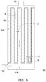
- FIG. 6 schematically illustrates a filtration chamber in the cells enrichment system of a microfluidic chip in accordance with an embodiment of the disclosure.
- the filtration chamber 160 in the present embodiment may be connected between an inlet channel 150 and an outlet channel 190 and may be an exemplary example of the filtration chamber 160A or 160B of the microfluidic chip 10 shown in FIG. 2 .
- the filtration chamber 160 includes a filtration wall 162 disposed within the filtration chamber 160 and the filtration wall 162 splits the filtration chamber 160 into a first sub-chamber 164A and a second sub-chamber 164B.
- the filtration wall 162 may be meandered in the filtration chamber 160.
- the sample fluid SP may enter the filtration chamber 160 from the inlet channel 150 and the filtration wall 162 may block the sorted target cells TG in the sample fluid SP to collect the sorted target cells TG in the first sub-chamber 164A.
- the liquid flow LF of the sample fluid SP may pass through the filtration wall 162 and enter the second sub-chamber 164B.
- the liquid flow LF of the sample fluid SP may leave from the filtration chamber 160 to the outlet channel 190 and be further drained away from the microfluidic chip via the outlet hole at the end of the outlet channel 190.
- FIG. 7 schematically illustrates an enlarged portion B of the filtration wall depicted in FIG. 6 .
- the filtration wall 162 includes a plurality of through slits 162A. Each of the plurality of through slits 162A crosses through the filtration wall 162 to form a fluid communication between the first sub-chamber 164A and the second sub-chamber 164B.
- a width W162A of each of the through silts 162A may be 5 ⁇ m
- a distance D162A between two adjacent through slits 162A may be 10 ⁇ m
- the filtration wall 162 may have 100 to 100,000 through silts 162A arranged therein.
- the total length of the filtration wall 162 may be determined based on the design requirement.
- FIG. 8 schematically illustrates an enlarged perspective view of a portion of the filtration wall.
- the filtration wall 162 dividing the first sub-chamber 164A and the second sub-chamber 164B includes a roof-like structure 162B arranged at a side of the filtration wall 162 facing the first sub-chamber 164A.
- the roof-like structure 162B is arranged between the through slits 162A and the first sub-chamber 164A as shown in FIG. 7 .
- the roof-like structure 162B defines a blocking edge BE and a recess RC indented from the blocking edge BE.
- the height HRC of the recess RC is smaller than the height H162 of the filtration wall 162 and the width WRC of the recess RC is smaller than the width W162 of the filtration wall 162.
- the height HRC of the recess RC and the width WRC of the recess RC may be determined based on the requirement and the design of the cells enrichment operation. For example, if the sample fluid for the cells enrichment operation is a whole blood sample and the target cells to-be enriched is the red blood cells, the height HRC of the recess RC may be 5 ⁇ m and the width WRC of the recess RC may be 10 ⁇ m.
- the blocking edge BE is able to block the sorted target cell TG in the first sub-chamber 164A.
- Each of the through slits 162A is opened at the recess RC so that the sorted target cell TG leaning against the blocking edge BE does not close or block the through slits 162A. Accordingly, though the sorted target cell TG is leant against the filtration wall 162, the fluid communication between the first sub-chamber 164A and the second sub-chamber 164B is smooth and easy via the through slits 162A.
- the sorted target cell TG may maintain its shape without being deformed by the flow stress of the fluid travelling from the first sub-chamber 164A to the second sub-chamber 164B.
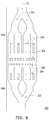
- FIG. 9 schematically illustrates a filter structure in accordance with an embodiment of the disclosure.
- the filter structure 300 may be an exemplary structure of the filter sections 114A, 114B, 124A, 124B, 134A and 134B and the anti-contamination sections 220A and 220B in the microfluidic chip 10 of FIG. 2 .
- the filter structure 300 may have a first portion 300A and a second portion 300B.
- Each of the first portion 300A and the second portion 300B includes a plurality of filter slits 302, a plurality of filter slits 304 and a plurality of filter slits 306.
- the fluid FL entering the filter structure 300 may firstly be separated into two sub-flows by the filter slits 302 of the first portion 300A, each sub-flow travelling in the filter slits 302 of the first portion 300A may further be separated into two sub-flows by the filter slits 304 of the first portion 300A, and each sub-flow travelling in the filter slits 304 of the first portion 300A may further be separated into two sub-flows by the filter slits 306 of the first portion 300A.
- the sub-flows travelling in the filter slits 306 of the first portion 300A may sequentially pass the filter slits 306, the filter slits 304 and the filter slits 302 of the second portion 300B.
- each secondary filter slits 304 may be 0.075mm and a width of each filter slit 306 may be 0.05mm.
- the position of the filter slit 306 of the second section 300B may not align with one filter slit 306 of the first section 300A, such that the particles passing through the filter slit 306 of the first section 300A may be blocked by the filter slit 306 of the second section 300B.
- the position of the filter slit 306 of the second section 300B may be corresponding to one separation structure between two adjacent filter slits 306 of the first section 300A.
- the microfluidic chip in accordance with the embodiment of the disclosure has two independent cells enrichment systems arranged in a symmetric manner so that the cells enrichment operation of the microfluidic chip may be performed to run two samples simultaneously, which improves the efficiency of enriching cells.
- the cells in the microfluidic chip are sorted before being collected so that the cells enrichment using the apparatus and/or the method of the disclosure may have high enriching rate of the target cells.
- the filtration wall of the filtration chamber in the cells enrichment system may have a roof-like structure to block the sorted cells before the through slits such that the fluid communication between two sub-chambers divided by the filtration wall may remain smooth and easy, which also helps to maintain the shape of the sorted cells.
Landscapes
- Chemical & Material Sciences (AREA)
- Health & Medical Sciences (AREA)
- Life Sciences & Earth Sciences (AREA)
- General Health & Medical Sciences (AREA)
- Organic Chemistry (AREA)
- Wood Science & Technology (AREA)
- Zoology (AREA)
- Bioinformatics & Cheminformatics (AREA)
- Engineering & Computer Science (AREA)
- Dispersion Chemistry (AREA)
- Biochemistry (AREA)
- Clinical Laboratory Science (AREA)
- Physics & Mathematics (AREA)
- Analytical Chemistry (AREA)
- Genetics & Genomics (AREA)
- General Engineering & Computer Science (AREA)
- Sustainable Development (AREA)
- Biotechnology (AREA)
- Biomedical Technology (AREA)
- Microbiology (AREA)
- Hematology (AREA)
- Chemical Kinetics & Catalysis (AREA)
- Fluid Mechanics (AREA)
- Molecular Biology (AREA)
- General Physics & Mathematics (AREA)
- Immunology (AREA)
- Pathology (AREA)
- Apparatus Associated With Microorganisms And Enzymes (AREA)
- Automatic Analysis And Handling Materials Therefor (AREA)
Claims (15)
- Zellanreicherungssystem (100) für einen Mikrofluidikchip, das Folgendes umfasst:einen ersten Fluidkanal (110, 110A, 110B);einen zweiten Fluidkanal (120, 120A, 120B);einen Probenkanal (130, 130A, 130B), der zwischen dem ersten Fluidkanal (110, 110A, 110B) und dem zweiten Fluidkanal (120, 120A, 120B) positioniert ist;einen Abfallkanal (140, 140A, 140B);einen Einlasskanal (150, 150A, 150B); undeine Filtrationskammer (160, 160A, 160B), die durch den Einlasskanal (150, 150A, 150B) erreicht wird, wobeider erste Fluidkanal (110, 110A, 110B), der zweite Fluidkanal (120, 120A, 120B) und der Probenkanal (130, 130A, 130B) auf einer ersten Seite einer Zusammenflusskammer (170, 170A, 170B) zusammenlaufen, der Abfallkanal (140, 140A, 140B) und der Einlasskanal (150, 150A, 150B) von einer zweiten Seite der Zusammenflusskammer (170, 170A, 170B) auseinanderlaufen, die erste Seite und die zweite Seite gegenüberliegende Seiten sind und der Einlasskanal (150, 150A, 150B) eine Fluidkommunikation zwischen der Filtrationskammer (160, 160A, 160B) und der Zusammenflusskammer (170, 170A, 170B) bildet;dadurch gekennzeichnet, dasseine Filtrationswand (162) in der Filtrationskammer (160, 160A, 160B) angeordnet ist und die Filtrationskammer (160, 160A, 160B) in eine erste Unterkammer (164A) und eine zweite Unterkammer (164B) teilt unddie Filtrationswand (162) Folgendes umfasst:mehrere Durchgangsschlitze (162A), wobei jeder der mehreren Durchgangsschlitze (162A) die Filtrationswand (162) durchquert, um eine Fluidkommunikation zwischen der ersten Unterkammer (164A) und der zweiten Unterkammer (164B) zu bilden, wobei die erste Unterkammer (164A) und die zweite Unterkammer (164B) jeweils bei gegenüberliegenden Enden der Durchgangsschlitze (162A) angeordnet sind, undeine dachartige Struktur (162B), die auf einer Seite der Filtrationswand (162) der ersten Unterkammer (164A) zugewandt angeordnet ist und zwischen den Durchgangsschlitzen (162A) und der ersten Unterkammer (164A) angeordnet ist, wobei die dachartige Struktur (162B) eine Sperrkante (BE) und eine Aussparung (RC), die von der Sperrkante (BE) eingerückt ist, definiert, wobei die Aussparung (RC) eine Höhe (HRC), die kleiner als die der Filtrationswand (162) ist, und eine Breite (WRC), die kleiner als die der Filtrationswand (162) ist, besitzt und jeder der Durchgangsschlitze (162A) bei der Aussparung (RC) geöffnet ist.
- Mikrofluidikchip (10), der ein erstes Zellanreicherungssystem (100, 100A) nach Anspruch 1 und ein zweites Zellanreicherungssystem (100, 100B) nach Anspruch 1 umfasst, wobei
ein Kanallayout des ersten Zellanreicherungssystems (100, 100A) und ein Kanallayout des zweiten Zellanreicherungssystems (100, 100B) in Bezug auf eine Reflexionsebene (RP), die zum Mikrofluidikchip (10) senkrecht ist, symmetrisch sind und
der Probenkanal (130, 130A, 130B) des ersten Zellanreicherungssystems (100, 100A) eine erste Innenwand (136A) und eine erste Außenwand (138A) besitzt, der Probenkanal (130, 130A, 130B) des zweiten Zellanreicherungssystems (100, 100B) eine zweite Innenwand (136B) und eine zweite Außenwand (138B) besitzt, die erste Außenwand (134A) und die zweite Außenwand (134B) weiter von der Reflexionsebene (RP) entfernt sind als die erste Innenwand (136A) bzw. die zweite Innenwand (136B) und ein Abstand (D) zwischen der ersten Außenwand (138A) und der zweiten Außenwand (138B) im Bereich von etwa 10 µm bis etwa 1 cm liegt. - Mikrofluidikchip (10) nach Anspruch 2, wobei der Abstand (D) zwischen der ersten Außenwand (138A) und der zweiten Außenwand (138B) im Bereich von etwa 700 µm bis etwa 1200 µm liegt.
- Mikrofluidikchip (10) nach Anspruch 2 oder 3, der ferner einen Reagenzeinlass (210) und einen Reagenzkanal (220) umfasst, wobei sich der Reagenzkanal (220) in einen ersten Zweig (222) und einen zweiten Zweig (224) gabelt, der erste Zweig (222) in Fluidkommunikation mit der Filtrationskammer (160, 160A, 160B) des ersten Zellanreicherungssystems (100, 100A) ist und der zweite Zweig (224) in Fluidkommunikation mit der Filtrationskammer (160, 160A, 160B) des zweiten Zellanreicherungssystems (100, 100B) ist, und wobei
sowohl der erste Zweig (222) als auch der zweite Zweig (224) des Reagenzkanals (220) einen Antiverunreinigungsabschnitt (220A, 220B) umfasst, in dem mehrere Filterschlitze (302, 304, 306) angeordnet sind. - Mikrofluidikchip (10) nach Anspruch 4, wobei der Reagenzkanal (220) ferner eine Blasenfallenkammer (230) umfasst, bevor er sich in den ersten Zweig (222) und den zweiten Zweig (224) gabelt.
- Mikrofluidikchip (10) nach einem der Ansprüche 2 bis 5, wobei sowohl das erste Zellanreicherungssystem (100, 100A) als auch das zweite Zellanreicherungssystem (100, 100B) ferner eine Abfallauslassöffnung (142A, 142B) umfasst, die durch eine Außenfläche des Mikrofluidikchips (10) verläuft und in Fluidkommunikation mit dem Abfallkanal (140, 140A, 140B) ist.
- Mikrofluidikchip (10) nach einem der Ansprüche 2 bis 6, wobei sowohl das erste Zellanreicherungssystem (100, 100A) als auch das zweite Zellanreicherungssystem (100, 100B) ferner einen Auslasskanal (190, 190A, 190B), der von der zweiten Unterkammer (164B) abgeht, und eine Auslassöffnung (192A, 192B), die durch eine Außenfläche des Mikrofluidikchips (10) verläuft und in Fluidkommunikation mit dem Auslasskanal (190, 190A, 190B) ist, umfasst.
- Mikrofluidikchip (10) nach einem der Ansprüche 2 bis 7, wobei sowohl das erste Zellanreicherungssystem (100, 100A) als auch das zweite Zellanreicherungssystem (100, 100B) ferner Folgendes umfasst:eine Probeneinlassöffnung (132A, 132B), die durch eine Außenfläche des Mikrofluidikchips (10) verläuft und in Fluidkommunikation mit dem Probenkanal (130, 130A, 130B) ist;eine erste Puffereinlassöffnung (112A, 112B), die durch die Außenfläche des Mikrofluidikchips (10) verläuft und in Fluidkommunikation mit dem ersten Fluidkanal (110, 110A, 110B) ist;eine zweite Puffereinlassöffnung (122A, 122B), die durch die Außenfläche des Mikrofluidikchips (10) verläuft und in Fluidkommunikation mit dem zweiten Fluidkanal (120, 120A, 120B) ist; undeine Pufferschaltöffnung (180A, 180B), die durch die Außenfläche des Mikrofluidikchips (10) verläuft und in Fluidkommunikation mit dem zweiten Fluidkanal (120, 120A, 120B) zwischen der zweiten Puffereinlassöffnung (122A, 122B) und der Zusammenflusskammer (170, 170A, 170B) ist.
- Vorrichtung zum Anreichern von Zellen, die Folgendes umfasst:einen Mikrofluidikchip (10), der ein erstes Zellanreicherungssystem (100, 100A) nach Anspruch 1 und ein zweites Zellanreicherungssystem (100, 100B) nach Anspruch 1 umfasst, insbesondere einen Mikrofluidikchip (10) nach einem der Ansprüche 2 bis 7;zwei Schalter (SW1, SW2), die mit dem zweiten Fluidkanal (120, 120A, 120B) des ersten Zellanreicherungssystems (100, 100A) bzw. dem zweiten Fluidkanal (120, 120A, 120B) des zweiten Zellanreicherungssystems (100, 100B) verbunden sind;einen Zelldetektor (DC), der ein Sichtfeld (VF) besitzt, wobei der Zelldetektor (DC) konfiguriert ist, eine Zielzelle (TG) in den Probenkanälen (130, 130A, 130B) des ersten Zellanreicherungssystems (100, 100A) und des zweiten Zellanreicherungssystems (100, 100B) zu detektieren; undeinen Prozessor (PR), der konfiguriert ist, die zwei Schalter (SW1, SW2) in Reaktion auf ein Detektionsergebnis des Zelldetektors (DC) unabhängig zu steuern, wobei der Prozessor (PR) nach einer Detektion der Zielzelle (TG) im Probenkanal (130, 130A, 130B) des ersten Zellanreicherungssystems (100, 100A) oder des zweiten Zellanreicherungssystems (100, 100B) den entsprechenden Schalter (SW1, SW2), der mit dem ersten Zellanreicherungssystem (100, 100A) oder dem zweiten Zellanreicherungssystem (100, 100B) verbunden ist, aktiviert.
- Vorrichtung zum Anreichern von Zellen nach Anspruch 9, die ferner Folgendes umfasst:eine erste Pufferversorgung (BS1) in Fluidkommunikation mit dem ersten Fluidkanal (110, 110A, 110B) sowohl des ersten Zellanreicherungssystems (100, 100A) als auch des zweiten Zellanreicherungssystems (100, 100B) undeine zweite Pufferversorgung (BS2) in Fluidkommunikation mit dem zweiten Fluidkanal (120, 120A, 120B) sowohl des ersten Zellanreicherungssystems (100, 100A) als auch des zweiten Zellanreicherungssystems (100, 100B), wobeieiner der Schalter (SW1, SW2) zwischen der zweiten Pufferversorgung (BS2) und dem zweiten Fluidkanal (120, 120A, 120B) des ersten Zellanreicherungssystems (100, 100A) verbunden ist und der andere Schalter (SW1, SW2) zwischen der zweiten Pufferversorgung (BS2) und dem zweiten Fluidkanal (120, 120A, 120B) des zweiten Zellanreicherungssystems (100, 100B) verbunden ist,der Prozessor (PR) ferner konfiguriert ist, die zweite Pufferversorgung (BS2) zu steuern, um einen Pufferstrom im zweiten Fluidkanal (120, 120A, 120B) sowohl des ersten Zellanreicherungssystems (100, 100A) als auch des zweiten Zellanreicherungssystems (100, 100B) zu bilden, und der Pufferstrom ein Probenfluid (SP) aus dem Probenkanal (130, 130A, 130B) derart leitet, dass es bei der Zusammenflusskammer (170, 170A, 170B) in den Abfallkanal (140, 140A, 140B) eintritt, undder Prozessor (PR) nach einer Detektion der Zielzelle (TG) den entsprechenden Schalter (SW1, SW2) aktiviert, um den Pufferstrom anzupassen, und der angepasste Pufferstrom das Probenfluid (SP) aus dem Probenkanal (130, 130A, 130B) derart leitet, dass es bei der Zusammenflusskammer (170, 170A, 170B) in den Einlasskanal (150, 150A, 150B) eintritt.
- Vorrichtung zum Anreichern von Zellen nach Anspruch 9 oder 10, wobei der Mikrofluidikchip (10) ferner einen Reagenzeinlass (210) und einen Reagenzkanal (220) umfasst und sich der Reagenzkanal (220) in zwei Zweige (222, 224) gabelt, die in Fluidkommunikation mit der Filtrationskammer (160, 160A, 160B) des ersten Zellanreicherungssystems (100, 100A) bzw. der Filtrationskammer (160, 160A, 160B) des zweiten Zellanreicherungssystems (100, 100B) sind.
- Verfahren zum Anreichern von Zellen in einem einen Mikrofluidikchip (10), wobei der einen Mikrofluidikchip (10) ein erstes Zellanreicherungssystem (100, 100A) nach Anspruch 1 und ein zweites Zellanreicherungssystem (100, 100B) nach Anspruch 1 umfasst und das Verfahren Folgendes umfasst:Zuführen eines ersten Pufferfluids (BF1) zum ersten Fluidkanal (110, 110A, 110B) und eines zweiten Pufferfluids (BF2) zum zweiten Fluidkanal (120, 120A, 120B) des ersten Zellanreicherungssystems (100, 100A);Einspeisen eines ersten Probenfluids (SP) in den Probenkanal (130, 130A, 130B) des ersten Zellanreicherungssystems (100, 100A) undSteuern des zweiten Pufferfluids (BF2) im zweiten Fluidkanal (120, 120A, 120B) des ersten Zellanreicherungssystems (100, 100A), um das erste Probenfluid (SP) derart zu leiten, dass es in den Abfallkanal (140, 140A, 140B) oder den Einlasskanal (150, 150A, 150B) des ersten Zellanreicherungssystems (100, 100A) eintritt.
- Verfahren nach Anspruch 12, das ferner Folgendes umfasst:Zuführen des ersten Pufferfluids (BF1) zum ersten Fluidkanal (110, 110A, 110B) des zweiten Zellanreicherungssystems (100, 100B) und des zweiten Pufferfluids (BF2) zum zweiten Fluidkanal (120, 120A, 120B) des zweiten Zellanreicherungssystems (100, 100B);Einspeisen eines zweiten Probenfluids (SP) in den Probenkanal (130, 130A, 130B) des zweiten Zellanreicherungssystems (100, 100B) undSteuern des zweiten Pufferfluids (BF2) im zweiten Fluidkanal (120, 120A, 120B) des zweiten Zellanreicherungssystems (100, 100B), um das zweite Probenfluid (SP) aus dem Probenkanal (130, 130A, 130B) des zweiten Zellanreicherungssystems (100, 100B) derart zu leiten, dass es in den Abfallkanal (140, 140A, 140B) oder den Einlasskanal (150, 150A, 150B) des zweiten Zellanreicherungssystems (100, 100B) eintritt, wobeidas Steuern des zweiten Pufferfluids (BF2) im zweiten Fluidkanal (120, 120A, 120B) des zweiten Zellanreicherungssystems (100, 100B) vom Steuern des zweiten Pufferfluids (BF2) im zweiten Fluidkanal (120, 120A, 120B) des ersten Zellanreicherungssystems (100, 100A) unabhängig ist.
- Verfahren nach Anspruch 13, wobei das zweite Pufferfluid (BF2) im zweiten Fluidkanal (120, 120A, 120B) des zweiten Zellanreicherungssystems (100, 100B) gesteuert wird, um das zweite Probenfluid (SP) aus dem Probenkanal (130, 130A, 130B) des zweiten Zellanreicherungssystems (100, 100B) derart zu leiten, dass es nach einer Detektion einer Zielzelle (TG) im Probenkanal (130, 130A, 130B) des zweiten Zellanreicherungssystems (100, 100B) in den Einlasskanal (150, 150A, 150B) des zweiten Zellanreicherungssystems (100, 100B) eintritt.
- Verfahren nach Anspruch 12 oder 13, wobei der Pufferstrom im zweiten Fluidkanal (120, 120A, 120B) des ersten Zellanreicherungssystems (100, 100A) gesteuert wird, um das erste Probenfluid (SP) aus dem Probenkanal (130, 130A, 130B) des ersten Zellanreicherungssystems (100, 100A) derart leitet, dass es nach einer Detektion einer Zielzelle (TG) im Probenkanal (130, 130A, 130B) des ersten Zellanreicherungssystems (100, 100A) in den Einlasskanal (150, 150A, 150B) des ersten Zellanreicherungssystems (100, 100A) eintritt.
Applications Claiming Priority (1)
| Application Number | Priority Date | Filing Date | Title |
|---|---|---|---|
| US201762504129P | 2017-05-10 | 2017-05-10 |
Publications (2)
| Publication Number | Publication Date |
|---|---|
| EP3401014A1 EP3401014A1 (de) | 2018-11-14 |
| EP3401014B1 true EP3401014B1 (de) | 2020-07-22 |
Family
ID=62148239
Family Applications (1)
| Application Number | Title | Priority Date | Filing Date |
|---|---|---|---|
| EP18171605.1A Active EP3401014B1 (de) | 2017-05-10 | 2018-05-09 | Mikrofluidischer chip, vorrichtung zur anreicherung von zellen und methode zur anreicherung von zellen in einem mikrofluidischen chip |
Country Status (5)
| Country | Link |
|---|---|
| US (1) | US10730049B2 (de) |
| EP (1) | EP3401014B1 (de) |
| JP (1) | JP6884727B2 (de) |
| CN (1) | CN108865664B (de) |
| TW (1) | TWI677464B (de) |
Cited By (1)
| Publication number | Priority date | Publication date | Assignee | Title |
|---|---|---|---|---|
| US11213824B2 (en) | 2017-03-29 | 2022-01-04 | The Research Foundation For The State University Of New York | Microfluidic device and methods |
Families Citing this family (15)
| Publication number | Priority date | Publication date | Assignee | Title |
|---|---|---|---|---|
| US10940477B2 (en) * | 2018-07-19 | 2021-03-09 | Micareo Taiwan Co., Ltd. | Fluid sample collection and retrieval apparatus and microfluidic chip |
| CN111909828B (zh) * | 2019-07-23 | 2024-08-06 | 北京大学 | 一种适用于循环肿瘤细胞捕获的微流控芯片 |
| CN112774743B (zh) * | 2019-11-07 | 2022-07-08 | 北京机械设备研究所 | 一种富集细胞的微流控芯片 |
| WO2021110870A1 (en) | 2019-12-05 | 2021-06-10 | Acib Gmbh | Method for producing a fermentation product |
| CN111855993A (zh) * | 2020-07-21 | 2020-10-30 | 北京化工大学 | 一种基于声波微流体的高灵敏度快速免疫检测方法和应用 |
| US20220088604A1 (en) | 2020-09-24 | 2022-03-24 | Micareo Taiwan Co., Ltd. | Microfluidic chip and device |
| US12287151B2 (en) * | 2021-02-26 | 2025-04-29 | Teradyne, Inc. | Thermal plate having a fluid channel |
| TWI773159B (zh) * | 2021-03-02 | 2022-08-01 | 國立清華大學 | 精子分選裝置及精子分選方法 |
| CN113188980B (zh) * | 2021-04-28 | 2022-09-16 | 南通大学 | 一种基于荧光激活细胞分选技术的全血循环肿瘤细胞级联分选的装置及方法 |
| CN113634296B (zh) * | 2021-10-19 | 2022-02-11 | 北京芯迈微生物技术有限公司 | 一种微流控芯片 |
| CN117907624B (zh) * | 2024-03-13 | 2024-05-17 | 江苏优众微纳半导体科技有限公司 | 基于微流控芯片的故障检测识别方法 |
| WO2025254518A1 (en) | 2024-06-07 | 2025-12-11 | Technische Universiteit Delft | Microfluidic device with pillars |
| NL2037897B1 (en) | 2024-06-07 | 2026-01-08 | Univ Delft Tech | Microfluidic device comprising a bubble trap |
| CN119746965B (zh) * | 2024-12-25 | 2025-07-18 | 广州国家实验室 | 无鞘流过滤分散结构、聚焦结构及过滤分散聚焦结构 |
| TWI910071B (zh) * | 2025-06-27 | 2025-12-21 | 信任生醫股份有限公司 | 直立式卡匣和樣本處理系統 |
Family Cites Families (16)
| Publication number | Priority date | Publication date | Assignee | Title |
|---|---|---|---|---|
| US6358387B1 (en) * | 2000-03-27 | 2002-03-19 | Caliper Technologies Corporation | Ultra high throughput microfluidic analytical systems and methods |
| SE0001768D0 (sv) | 2000-05-12 | 2000-05-12 | Helen Andersson | Mikrofluidisk flödescell för manipulering av partiklar |
| AU2003224817B2 (en) | 2002-04-01 | 2008-11-06 | Fluidigm Corporation | Microfluidic particle-analysis systems |
| US7118676B2 (en) * | 2003-09-04 | 2006-10-10 | Arryx, Inc. | Multiple laminar flow-based particle and cellular separation with laser steering |
| CA2513424A1 (en) | 2003-01-14 | 2004-08-05 | Micronics Inc. | Microfluidic devices for fluid manipulation and analysis |
| EP1668355A4 (de) * | 2003-08-28 | 2011-11-09 | Celula Inc | Verfahren und vorrichtung zur sortierung von zellen unter verwendung eines optischen schalters in einem mikrofluidischen kanalnetzwerk |
| US8921102B2 (en) * | 2005-07-29 | 2014-12-30 | Gpb Scientific, Llc | Devices and methods for enrichment and alteration of circulating tumor cells and other particles |
| US8822206B2 (en) * | 2005-10-11 | 2014-09-02 | The Johns Hopkins University | Device for high-throughput stimulation, immunostaining, and visualization of single cells |
| US7964078B2 (en) * | 2005-11-07 | 2011-06-21 | The Regents Of The University Of California | Microfluidic device for cell and particle separation |
| US8691164B2 (en) * | 2007-04-20 | 2014-04-08 | Celula, Inc. | Cell sorting system and methods |
| US20100267092A1 (en) * | 2009-02-09 | 2010-10-21 | Frederic Zenhausern | Components |
| JP5712396B2 (ja) | 2012-03-30 | 2015-05-07 | 公益財団法人神奈川科学技術アカデミー | イメージングセルソーター |
| US10371622B2 (en) * | 2013-03-14 | 2019-08-06 | Inguran, Llc | Device for high throughput sperm sorting |
| US10527626B2 (en) * | 2013-07-05 | 2020-01-07 | University Of Washington Through Its Center For Commercialization | Methods, compositions and systems for microfluidic assays |
| CN103627635B (zh) * | 2013-11-18 | 2015-05-20 | 辽宁中医药大学 | 一种用于细胞迁移和侵袭实验的多功能微流控芯片 |
| CN106190774A (zh) * | 2016-07-22 | 2016-12-07 | 深圳睿思生命科技有限公司 | 用于捕获循环肿瘤细胞的微流控芯片及其捕获和鉴定方法 |
-
2018
- 2018-05-09 EP EP18171605.1A patent/EP3401014B1/de active Active
- 2018-05-09 TW TW107115684A patent/TWI677464B/zh active
- 2018-05-10 JP JP2018091081A patent/JP6884727B2/ja active Active
- 2018-05-10 CN CN201810443499.1A patent/CN108865664B/zh active Active
- 2018-05-10 US US15/975,794 patent/US10730049B2/en active Active
Non-Patent Citations (1)
| Title |
|---|
| None * |
Cited By (2)
| Publication number | Priority date | Publication date | Assignee | Title |
|---|---|---|---|---|
| US11213824B2 (en) | 2017-03-29 | 2022-01-04 | The Research Foundation For The State University Of New York | Microfluidic device and methods |
| US11911763B2 (en) | 2017-03-29 | 2024-02-27 | The Research Foundation For The State University Of New York | Microfluidic device and methods |
Also Published As
| Publication number | Publication date |
|---|---|
| EP3401014A1 (de) | 2018-11-14 |
| US20180326419A1 (en) | 2018-11-15 |
| TW201900543A (zh) | 2019-01-01 |
| CN108865664A (zh) | 2018-11-23 |
| JP6884727B2 (ja) | 2021-06-09 |
| US10730049B2 (en) | 2020-08-04 |
| CN108865664B (zh) | 2021-11-26 |
| JP2018186814A (ja) | 2018-11-29 |
| TWI677464B (zh) | 2019-11-21 |
Similar Documents
| Publication | Publication Date | Title |
|---|---|---|
| EP3401014B1 (de) | Mikrofluidischer chip, vorrichtung zur anreicherung von zellen und methode zur anreicherung von zellen in einem mikrofluidischen chip | |
| EP2139984B1 (de) | Zellsortierungssystem | |
| US12188858B2 (en) | Microfluidic system with combined electrical and optical detection for high accuracy particle sorting and methods thereof | |
| KR100746431B1 (ko) | 셀 소터 칩 | |
| EP3597297B1 (de) | Vorrichtung zum sammeln von flüssigen proben und zum gewinnen von partikeln, sowie mikrofluidischer chip | |
| CN102472702B (zh) | 一种检测样品中的颗粒的方法 | |
| WO2008036083A1 (en) | Microfluidic flow cytometer and applications of same | |
| WO2017069824A1 (en) | Particle manipulation system with spiral focusing channel | |
| EP3821979A1 (de) | Verbessertes verfahren zum sortieren von zellen mit einem mikrogefertigten ventil | |
| US20170312749A1 (en) | Particle manipulation system with spiral focusing channel | |
| CN119175121A (zh) | 粒子分离芯片及粒子分离装置 | |
| HK1145335A (en) | Cell sorting system and methods | |
| HK1145335B (en) | Cell sorting system and methods |
Legal Events
| Date | Code | Title | Description |
|---|---|---|---|
| PUAI | Public reference made under article 153(3) epc to a published international application that has entered the european phase |
Free format text: ORIGINAL CODE: 0009012 |
|
| STAA | Information on the status of an ep patent application or granted ep patent |
Free format text: STATUS: THE APPLICATION HAS BEEN PUBLISHED |
|
| AK | Designated contracting states |
Kind code of ref document: A1 Designated state(s): AL AT BE BG CH CY CZ DE DK EE ES FI FR GB GR HR HU IE IS IT LI LT LU LV MC MK MT NL NO PL PT RO RS SE SI SK SM TR |
|
| AX | Request for extension of the european patent |
Extension state: BA ME |
|
| STAA | Information on the status of an ep patent application or granted ep patent |
Free format text: STATUS: REQUEST FOR EXAMINATION WAS MADE |
|
| 17P | Request for examination filed |
Effective date: 20181116 |
|
| RBV | Designated contracting states (corrected) |
Designated state(s): AL AT BE BG CH CY CZ DE DK EE ES FI FR GB GR HR HU IE IS IT LI LT LU LV MC MK MT NL NO PL PT RO RS SE SI SK SM TR |
|
| STAA | Information on the status of an ep patent application or granted ep patent |
Free format text: STATUS: EXAMINATION IS IN PROGRESS |
|
| 17Q | First examination report despatched |
Effective date: 20191029 |
|
| GRAP | Despatch of communication of intention to grant a patent |
Free format text: ORIGINAL CODE: EPIDOSNIGR1 |
|
| STAA | Information on the status of an ep patent application or granted ep patent |
Free format text: STATUS: GRANT OF PATENT IS INTENDED |
|
| INTG | Intention to grant announced |
Effective date: 20200219 |
|
| GRAS | Grant fee paid |
Free format text: ORIGINAL CODE: EPIDOSNIGR3 |
|
| GRAA | (expected) grant |
Free format text: ORIGINAL CODE: 0009210 |
|
| STAA | Information on the status of an ep patent application or granted ep patent |
Free format text: STATUS: THE PATENT HAS BEEN GRANTED |
|
| AK | Designated contracting states |
Kind code of ref document: B1 Designated state(s): AL AT BE BG CH CY CZ DE DK EE ES FI FR GB GR HR HU IE IS IT LI LT LU LV MC MK MT NL NO PL PT RO RS SE SI SK SM TR |
|
| REG | Reference to a national code |
Ref country code: GB Ref legal event code: FG4D |
|
| REG | Reference to a national code |
Ref country code: CH Ref legal event code: EP |
|
| REG | Reference to a national code |
Ref country code: DE Ref legal event code: R096 Ref document number: 602018006168 Country of ref document: DE |
|
| REG | Reference to a national code |
Ref country code: AT Ref legal event code: REF Ref document number: 1292903 Country of ref document: AT Kind code of ref document: T Effective date: 20200815 |
|
| REG | Reference to a national code |
Ref country code: IE Ref legal event code: FG4D |
|
| REG | Reference to a national code |
Ref country code: LT Ref legal event code: MG4D |
|
| REG | Reference to a national code |
Ref country code: AT Ref legal event code: MK05 Ref document number: 1292903 Country of ref document: AT Kind code of ref document: T Effective date: 20200722 |
|
| PG25 | Lapsed in a contracting state [announced via postgrant information from national office to epo] |
Ref country code: ES Free format text: LAPSE BECAUSE OF FAILURE TO SUBMIT A TRANSLATION OF THE DESCRIPTION OR TO PAY THE FEE WITHIN THE PRESCRIBED TIME-LIMIT Effective date: 20200722 Ref country code: GR Free format text: LAPSE BECAUSE OF FAILURE TO SUBMIT A TRANSLATION OF THE DESCRIPTION OR TO PAY THE FEE WITHIN THE PRESCRIBED TIME-LIMIT Effective date: 20201023 Ref country code: BG Free format text: LAPSE BECAUSE OF FAILURE TO SUBMIT A TRANSLATION OF THE DESCRIPTION OR TO PAY THE FEE WITHIN THE PRESCRIBED TIME-LIMIT Effective date: 20201022 Ref country code: NO Free format text: LAPSE BECAUSE OF FAILURE TO SUBMIT A TRANSLATION OF THE DESCRIPTION OR TO PAY THE FEE WITHIN THE PRESCRIBED TIME-LIMIT Effective date: 20201022 Ref country code: AT Free format text: LAPSE BECAUSE OF FAILURE TO SUBMIT A TRANSLATION OF THE DESCRIPTION OR TO PAY THE FEE WITHIN THE PRESCRIBED TIME-LIMIT Effective date: 20200722 Ref country code: PT Free format text: LAPSE BECAUSE OF FAILURE TO SUBMIT A TRANSLATION OF THE DESCRIPTION OR TO PAY THE FEE WITHIN THE PRESCRIBED TIME-LIMIT Effective date: 20201123 Ref country code: FI Free format text: LAPSE BECAUSE OF FAILURE TO SUBMIT A TRANSLATION OF THE DESCRIPTION OR TO PAY THE FEE WITHIN THE PRESCRIBED TIME-LIMIT Effective date: 20200722 Ref country code: LT Free format text: LAPSE BECAUSE OF FAILURE TO SUBMIT A TRANSLATION OF THE DESCRIPTION OR TO PAY THE FEE WITHIN THE PRESCRIBED TIME-LIMIT Effective date: 20200722 Ref country code: SE Free format text: LAPSE BECAUSE OF FAILURE TO SUBMIT A TRANSLATION OF THE DESCRIPTION OR TO PAY THE FEE WITHIN THE PRESCRIBED TIME-LIMIT Effective date: 20200722 Ref country code: HR Free format text: LAPSE BECAUSE OF FAILURE TO SUBMIT A TRANSLATION OF THE DESCRIPTION OR TO PAY THE FEE WITHIN THE PRESCRIBED TIME-LIMIT Effective date: 20200722 |
|
| PG25 | Lapsed in a contracting state [announced via postgrant information from national office to epo] |
Ref country code: LV Free format text: LAPSE BECAUSE OF FAILURE TO SUBMIT A TRANSLATION OF THE DESCRIPTION OR TO PAY THE FEE WITHIN THE PRESCRIBED TIME-LIMIT Effective date: 20200722 Ref country code: PL Free format text: LAPSE BECAUSE OF FAILURE TO SUBMIT A TRANSLATION OF THE DESCRIPTION OR TO PAY THE FEE WITHIN THE PRESCRIBED TIME-LIMIT Effective date: 20200722 Ref country code: RS Free format text: LAPSE BECAUSE OF FAILURE TO SUBMIT A TRANSLATION OF THE DESCRIPTION OR TO PAY THE FEE WITHIN THE PRESCRIBED TIME-LIMIT Effective date: 20200722 Ref country code: IS Free format text: LAPSE BECAUSE OF FAILURE TO SUBMIT A TRANSLATION OF THE DESCRIPTION OR TO PAY THE FEE WITHIN THE PRESCRIBED TIME-LIMIT Effective date: 20201122 |
|
| PG25 | Lapsed in a contracting state [announced via postgrant information from national office to epo] |
Ref country code: NL Free format text: LAPSE BECAUSE OF FAILURE TO SUBMIT A TRANSLATION OF THE DESCRIPTION OR TO PAY THE FEE WITHIN THE PRESCRIBED TIME-LIMIT Effective date: 20200722 |
|
| REG | Reference to a national code |
Ref country code: DE Ref legal event code: R097 Ref document number: 602018006168 Country of ref document: DE |
|
| PG25 | Lapsed in a contracting state [announced via postgrant information from national office to epo] |
Ref country code: IT Free format text: LAPSE BECAUSE OF FAILURE TO SUBMIT A TRANSLATION OF THE DESCRIPTION OR TO PAY THE FEE WITHIN THE PRESCRIBED TIME-LIMIT Effective date: 20200722 Ref country code: SM Free format text: LAPSE BECAUSE OF FAILURE TO SUBMIT A TRANSLATION OF THE DESCRIPTION OR TO PAY THE FEE WITHIN THE PRESCRIBED TIME-LIMIT Effective date: 20200722 Ref country code: EE Free format text: LAPSE BECAUSE OF FAILURE TO SUBMIT A TRANSLATION OF THE DESCRIPTION OR TO PAY THE FEE WITHIN THE PRESCRIBED TIME-LIMIT Effective date: 20200722 Ref country code: RO Free format text: LAPSE BECAUSE OF FAILURE TO SUBMIT A TRANSLATION OF THE DESCRIPTION OR TO PAY THE FEE WITHIN THE PRESCRIBED TIME-LIMIT Effective date: 20200722 Ref country code: CZ Free format text: LAPSE BECAUSE OF FAILURE TO SUBMIT A TRANSLATION OF THE DESCRIPTION OR TO PAY THE FEE WITHIN THE PRESCRIBED TIME-LIMIT Effective date: 20200722 Ref country code: DK Free format text: LAPSE BECAUSE OF FAILURE TO SUBMIT A TRANSLATION OF THE DESCRIPTION OR TO PAY THE FEE WITHIN THE PRESCRIBED TIME-LIMIT Effective date: 20200722 |
|
| PLBE | No opposition filed within time limit |
Free format text: ORIGINAL CODE: 0009261 |
|
| STAA | Information on the status of an ep patent application or granted ep patent |
Free format text: STATUS: NO OPPOSITION FILED WITHIN TIME LIMIT |
|
| PG25 | Lapsed in a contracting state [announced via postgrant information from national office to epo] |
Ref country code: AL Free format text: LAPSE BECAUSE OF FAILURE TO SUBMIT A TRANSLATION OF THE DESCRIPTION OR TO PAY THE FEE WITHIN THE PRESCRIBED TIME-LIMIT Effective date: 20200722 |
|
| 26N | No opposition filed |
Effective date: 20210423 |
|
| PG25 | Lapsed in a contracting state [announced via postgrant information from national office to epo] |
Ref country code: SK Free format text: LAPSE BECAUSE OF FAILURE TO SUBMIT A TRANSLATION OF THE DESCRIPTION OR TO PAY THE FEE WITHIN THE PRESCRIBED TIME-LIMIT Effective date: 20200722 |
|
| PG25 | Lapsed in a contracting state [announced via postgrant information from national office to epo] |
Ref country code: SI Free format text: LAPSE BECAUSE OF FAILURE TO SUBMIT A TRANSLATION OF THE DESCRIPTION OR TO PAY THE FEE WITHIN THE PRESCRIBED TIME-LIMIT Effective date: 20200722 |
|
| REG | Reference to a national code |
Ref country code: NL Ref legal event code: MP Effective date: 20200722 |
|
| REG | Reference to a national code |
Ref country code: CH Ref legal event code: PL |
|
| PG25 | Lapsed in a contracting state [announced via postgrant information from national office to epo] |
Ref country code: LI Free format text: LAPSE BECAUSE OF NON-PAYMENT OF DUE FEES Effective date: 20210531 Ref country code: LU Free format text: LAPSE BECAUSE OF NON-PAYMENT OF DUE FEES Effective date: 20210509 Ref country code: MC Free format text: LAPSE BECAUSE OF FAILURE TO SUBMIT A TRANSLATION OF THE DESCRIPTION OR TO PAY THE FEE WITHIN THE PRESCRIBED TIME-LIMIT Effective date: 20200722 Ref country code: CH Free format text: LAPSE BECAUSE OF NON-PAYMENT OF DUE FEES Effective date: 20210531 |
|
| REG | Reference to a national code |
Ref country code: BE Ref legal event code: MM Effective date: 20210531 |
|
| PG25 | Lapsed in a contracting state [announced via postgrant information from national office to epo] |
Ref country code: IE Free format text: LAPSE BECAUSE OF NON-PAYMENT OF DUE FEES Effective date: 20210509 |
|
| PG25 | Lapsed in a contracting state [announced via postgrant information from national office to epo] |
Ref country code: BE Free format text: LAPSE BECAUSE OF NON-PAYMENT OF DUE FEES Effective date: 20210531 |
|
| PG25 | Lapsed in a contracting state [announced via postgrant information from national office to epo] |
Ref country code: CY Free format text: LAPSE BECAUSE OF FAILURE TO SUBMIT A TRANSLATION OF THE DESCRIPTION OR TO PAY THE FEE WITHIN THE PRESCRIBED TIME-LIMIT Effective date: 20200722 |
|
| PG25 | Lapsed in a contracting state [announced via postgrant information from national office to epo] |
Ref country code: HU Free format text: LAPSE BECAUSE OF FAILURE TO SUBMIT A TRANSLATION OF THE DESCRIPTION OR TO PAY THE FEE WITHIN THE PRESCRIBED TIME-LIMIT; INVALID AB INITIO Effective date: 20180509 |
|
| PG25 | Lapsed in a contracting state [announced via postgrant information from national office to epo] |
Ref country code: MK Free format text: LAPSE BECAUSE OF FAILURE TO SUBMIT A TRANSLATION OF THE DESCRIPTION OR TO PAY THE FEE WITHIN THE PRESCRIBED TIME-LIMIT Effective date: 20200722 |
|
| PG25 | Lapsed in a contracting state [announced via postgrant information from national office to epo] |
Ref country code: TR Free format text: LAPSE BECAUSE OF FAILURE TO SUBMIT A TRANSLATION OF THE DESCRIPTION OR TO PAY THE FEE WITHIN THE PRESCRIBED TIME-LIMIT Effective date: 20200722 |
|
| PG25 | Lapsed in a contracting state [announced via postgrant information from national office to epo] |
Ref country code: MT Free format text: LAPSE BECAUSE OF FAILURE TO SUBMIT A TRANSLATION OF THE DESCRIPTION OR TO PAY THE FEE WITHIN THE PRESCRIBED TIME-LIMIT Effective date: 20200722 |
|
| PGFP | Annual fee paid to national office [announced via postgrant information from national office to epo] |
Ref country code: DE Payment date: 20250522 Year of fee payment: 8 |
|
| PGFP | Annual fee paid to national office [announced via postgrant information from national office to epo] |
Ref country code: GB Payment date: 20250521 Year of fee payment: 8 |
|
| PGFP | Annual fee paid to national office [announced via postgrant information from national office to epo] |
Ref country code: FR Payment date: 20250520 Year of fee payment: 8 |