EP3401125A1 - Profil de bande de roulement d'un pneu de véhicule - Google Patents
Profil de bande de roulement d'un pneu de véhicule Download PDFInfo
- Publication number
- EP3401125A1 EP3401125A1 EP18157339.5A EP18157339A EP3401125A1 EP 3401125 A1 EP3401125 A1 EP 3401125A1 EP 18157339 A EP18157339 A EP 18157339A EP 3401125 A1 EP3401125 A1 EP 3401125A1
- Authority
- EP
- European Patent Office
- Prior art keywords
- extension
- extension portion
- sipe
- circumferential
- sipes
- Prior art date
- Legal status (The legal status is an assumption and is not a legal conclusion. Google has not performed a legal analysis and makes no representation as to the accuracy of the status listed.)
- Granted
Links
Images

Classifications
-
- B—PERFORMING OPERATIONS; TRANSPORTING
- B60—VEHICLES IN GENERAL
- B60C—VEHICLE TYRES; TYRE INFLATION; TYRE CHANGING; CONNECTING VALVES TO INFLATABLE ELASTIC BODIES IN GENERAL; DEVICES OR ARRANGEMENTS RELATED TO TYRES
- B60C11/00—Tyre tread bands; Tread patterns; Anti-skid inserts
- B60C11/03—Tread patterns
- B60C11/12—Tread patterns characterised by the use of narrow slits or incisions, e.g. sipes
- B60C11/1236—Tread patterns characterised by the use of narrow slits or incisions, e.g. sipes with special arrangements in the tread pattern
- B60C11/125—Tread patterns characterised by the use of narrow slits or incisions, e.g. sipes with special arrangements in the tread pattern arranged at the groove bottom
-
- B—PERFORMING OPERATIONS; TRANSPORTING
- B60—VEHICLES IN GENERAL
- B60C—VEHICLE TYRES; TYRE INFLATION; TYRE CHANGING; CONNECTING VALVES TO INFLATABLE ELASTIC BODIES IN GENERAL; DEVICES OR ARRANGEMENTS RELATED TO TYRES
- B60C11/00—Tyre tread bands; Tread patterns; Anti-skid inserts
- B60C11/03—Tread patterns
- B60C11/0304—Asymmetric patterns
-
- B—PERFORMING OPERATIONS; TRANSPORTING
- B60—VEHICLES IN GENERAL
- B60C—VEHICLE TYRES; TYRE INFLATION; TYRE CHANGING; CONNECTING VALVES TO INFLATABLE ELASTIC BODIES IN GENERAL; DEVICES OR ARRANGEMENTS RELATED TO TYRES
- B60C11/00—Tyre tread bands; Tread patterns; Anti-skid inserts
- B60C11/03—Tread patterns
- B60C11/0306—Patterns comprising block rows or discontinuous ribs
-
- B—PERFORMING OPERATIONS; TRANSPORTING
- B60—VEHICLES IN GENERAL
- B60C—VEHICLE TYRES; TYRE INFLATION; TYRE CHANGING; CONNECTING VALVES TO INFLATABLE ELASTIC BODIES IN GENERAL; DEVICES OR ARRANGEMENTS RELATED TO TYRES
- B60C11/00—Tyre tread bands; Tread patterns; Anti-skid inserts
- B60C11/03—Tread patterns
- B60C11/0306—Patterns comprising block rows or discontinuous ribs
- B60C11/0309—Patterns comprising block rows or discontinuous ribs further characterised by the groove cross-section
Definitions
- the invention relates to a tread pattern of a vehicle tire - in particular a car vehicle tire - with separate by circumferential grooves profile strips and formed in profile bands sipes, with a profile band, in which sipes with a first extension portion with the largest directional component of the extension in the circumferential direction U and a second Extension section with the largest directional component in the axial direction A, which opens into a circumferential groove are formed, wherein first sipes whose second extension section opens into a circumferential groove bounding the profile band, and second sipes are formed, the second extension section opens into another circumferential groove bounding the profile band ,
- tread ribs in the central region of a tread pattern of a passenger vehicle tire with fine incisions, which are usually aligned at an oblique angle of 45 degrees to the circumferential direction. This makes it possible to achieve a compromise in noise excitation, abrasion properties and shape complexity.
- such a design is at the expense of wet braking properties, since the sipes then hardly provide edges for transmitting the braking forces available.
- From the DE 10 2012 108 384 A1 is a tread pattern of a pneumatic vehicle tire with peripheral grooves separated by circumferential grooves known in which in a circumferential rib sipes with a first extension portion in which the sipe extends completely in the circumferential direction and with a second extension portion, in which the sipe is oriented obliquely to the circumferential groove and thereby has a larger directional component in the axial direction than in the circumferential direction.
- the substantially axial extension portion opens into the one circumferential groove and second sipes whose substantially axial extension portion opens into the other circumferential groove.
- the first and second sipes are arranged in the circumferential rib in succession so that their circumferentially extending first extension portions are each arranged in the same axial position in the circumferential rib and are thus arranged on a line extending over the circumference of the vehicle pneumatic tire behind the other.
- the training allows with their aligned in the pure circumferential direction first extension portions of the sipes a recording of the water and a derivative by the transverse second extension portions in the adjacent circumferential grooves and due to the pure circumferential orientation of the first extension portion and the oblique orientation of the second extension portion of each of the sipes a Reduction of noise.
- the handling is further improved and thereby favors by the extension portions of the sipes with substantially axial direction component wet brakes ,
- the invention has for its object to enable in such a vehicle tire with profiled strip and sipes reduced noise with good wet handling and wet braking properties.
- the object is achieved by the formation of a tread pattern of a vehicle tire - in particular a vehicle tire - separated by circumferential grooves profile bands and formed in profile bands fine incisions, with a profile band, in which sipes with a first extension portion with the largest directional component of the extension in the circumferential direction U and formed with a second extension portion with the largest directional component in the axial direction A, which opens into a circumferential groove, wherein first sipes whose second extension portion opens into a circumferential groove bounding the profile band, and second sipes are formed, the second extension portion in another the Profile band bounding circumferential groove opens, solved according to the features of claim 1, in which over the circumference of the profile strip away from each pair of axially juxtaposed first n and second sipes are formed, the first extension portion are aligned parallel to each other and positioned in their circumferential extent with overlap to each other, wherein the second extension portions of the two sipes axially spaced from each other are positioned, and in which
- This design makes it possible, in such a pneumatic vehicle tire in a profile band by the pairwise formation of sipes a high number of substantially circumferentially oriented sipe sections and thus an increased number of grip edges for the transmission of shear forces and thereby an increased number of extension sections of sipes with larger axial extension direction component to provide for transmission of circumferentially directed forces.
- a high number of grip edges can be provided in a simple manner for better wet grip as well as for achieving improved wet handling behavior.
- the pairwise arrangement of the sipes with axial spacing of their second extension sections relative to one another and with their first extension sections aligned in parallel makes it possible to ensure a stiff core region of the profile strip over the circumference of the tire, whereby good dry and wet handling properties can be further improved.
- the formation of the sipes with their large extension portions in the circumferential direction further promotes the achievement of a low noise level.
- the formation of one of the two sipes with a chamfer, which extends to the circumferential groove, thereby favors despite high grip edge number of the paired arrangement of sipes ensuring the formation of noise at a very low level.
- the paired arrangement and the chamfer also favor a reliable good drainage from the area of the profile band to the circumferential groove.
- a vehicle tire according to the features of claim 5, wherein the sipe has a kink in the course at which the first extension portion adjacent to the second extension portion, and wherein the chamfered region in a profile band from the circumferential groove on the second extension portion of the sipe, is extended over the kink point into the first extension portion of the sipe and - in particular at a distance from the direction away from the kink point extending end of the first extension portion - ends.
- the water drainage effect can be implemented by the bevel in the circumferential groove particularly effective.
- This allows for an optimal compromise for achieving additionally good dry handling properties. This is particularly effective when using axially outer profile bands of the vehicle tire.
- a vehicle tire according to the features of claim 7, wherein the second extension portion aligned in its extension course including an inclination angle ⁇ with 0 ° ⁇ 30 ° - in particular with 0 ° ⁇ 20 ° - to the axial direction A. is, and wherein in particular the first extension portion is aligned in its extension course, including an inclination angle ⁇ with 0 ° ⁇ 15 ° to the circumferential direction U.
- a vehicle tire according to the features of claim 8, wherein in a profile band, the two sipes of a pair in their extension direction, starting from the respective circumferential groove over the second extension portion and the first extension portion to the direction away from the second extension portion extension end of the first extension portion and thus of the fine incision are aligned with mutually opposite orientation of the circumferential extent.
- a vehicle tire according to the features of claim 9, wherein in a profile band, the two sipes of a pair in their extension direction, starting from the respective circumferential groove over the second extension portion and the first extension portion to the direction away from the second extension portion extension end of the first extension portion and thus of the sipe are aligned with the same orientation of the circumferential extent.
- a vehicle tire according to the features of claim 10, wherein the one fine incision of a pair with a measured in the circumferential direction U greater overall length L 1 than the other sipe is formed, each of which in the circumferential direction U, starting from the junction of the second extension portion of the respective sipe in the circumferential groove over the second extension portion and the first extension portion up to the second end portion pointing away extension end of the first extension portion and thus of the sipe indicated length, wherein in the longer sipe the total extension length L 1 and measured in the circumferential direction U extension length L 2 of the first extension portion are formed with 15mm ⁇ L 1 ⁇ 30mm and 0.6L 1 ⁇ L 2 ⁇ L 1 . This allows optimal implementation within the pitch lengths of conventional car tires.
- the shorter sipe of the pair is formed with a measured in the circumferential direction U total length of extension L 3, wherein in the shorter sipe, the total length of extension L 3 and measured in the peripheral direction U extending length L 4 of the first extension portion are formed with (1/3) L 1 ⁇ L 3 ⁇ L 1 and 0.6L 3 ⁇ L 4 ⁇ L 3 .
- This allows in a simple manner good conversions to achieve very good wet handling properties and wet braking properties with very low noise and good dry handling properties.
- a vehicle tire according to the features of claim 12 wherein the shorter sipe of the pair in the axial direction A respectively on the outside of the vehicle (OU) indicative side of the profile strip of the tire and the longer to the vehicle inner side (IN) indicative side of the profile strip of the tire is positioned.
- the side of the profiled strip which points to the vehicle outer side (OU) and which is important for dry handling properties is formed in a simple manner with increased transverse rigidity and thus with greater stability for dry handling, whereby the dry handling properties can be further improved.
- the circumferential rigidity of the profiled strip can be reduced in a simple manner, especially in the second section of the sipe which substantially influences the circumferential rigidity, which promotes low rolling resistance and wet-setting properties, such as wet brakes.
- a vehicle tire according to the features of claim 14 wherein the sipes of a pair with their first extension portion at a distance a with 2mm ⁇ a ⁇ 10mm - in particular with 5mm ⁇ a ⁇ 8mm - are formed to each other.
- the formation of the pairs to achieve good wet handling properties and wet braking properties can be implemented with very low noise in a particularly simple manner with sufficiently high stability of the profile band.
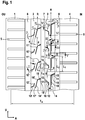
- Fig.1 shows a tread pattern of a pneumatic vehicle tire of a passenger car (passenger car), in which a plurality of circumferentially extending over the entire circumference of the pneumatic vehicle tire circumferential ribs 1, 2, 3 and 4 in the axial direction A of the pneumatic vehicle tire are arranged side by side.
- the circumferential ribs 1 and 2 are separated from each other in the axial direction A by a circumferential groove 6, which extends over the entire circumference of the vehicle pneumatic tire and is aligned in the circumferential direction U.
- the circumferential ribs 2 and 3 are separated from one another in the axial direction A of the pneumatic vehicle tire by a circumferential groove 7 which extends over the entire circumference of the vehicle pneumatic tire and is aligned in the circumferential direction U.
- the circumferential ribs 3 and 4 are separated from one another in the axial direction A by a circumferential groove 8 which extends over the entire circumference of the pneumatic vehicle tire and is aligned in the circumferential direction U.
- the circumferential ribs 1 and 4 are each formed as formed in a tire shoulder shoulder ribs. In this case, the circumferential rib 1 is formed in the shoulder facing the vehicle outside the vehicle OU and the circumferential rib 4 is formed in the shoulder facing the vehicle inside IN in the vehicle.
- the circumferential ribs 2 and 3 are formed between the shoulder ribs formed as circumferential ribs 1 and 4 as the central circumferential ribs. As in Fig.1 is illustrated, the ground contact width T A of the pneumatic vehicle tire extends from an axial extension region within the circumferential rib 1 to a position in the axial extension region of the circumferential rib 4.
- transverse grooves 5 of known type are formed, which, starting from the adjacent to the respective circumferential rib 1 and 4 circumferential groove 6 and 8 in the axial direction A to the axial extension area outside the ground contact width T A extends and ends there.
- profile block rows of known type are formed in the region of the tire shoulder.
- the circumferential rib 3 As in the FIGS. 2 to 6 is illustrated by the circumferential rib 3, the circumferential ribs 1, 2, 3 and 4 in the radial direction R outwardly by a in the extension region of the ground contact width T A forming the ground contact surface, radially outer surface 19 is limited.
- sipes 10 and 11 are formed.
- the sipes 10 are formed from a second extension section 13 extending from the circumferential groove 7 to a kink 17 and from a first extension section 12 connected to the second extension section 13 in a kinked position 17.
- the fine incisions 11 are formed from a second extension section 15 extending from the circumferential groove 8 to a kink 16 and from a first extension section 14 connected to the second extension section 15 at the kinking point.
- the first extension section 14 of the sipe 11 extends between kink 16 to a direction away from the respective kink 16 extension end of the fine incision 11.
- the first extension portion 12 of the sipe 10 extends between kink 17 to a direction away from the respective kink 17 extension end of the sipe 10.
- the sipes 11 and 10 of a pair are in their respective first extension portion 14 and 12 of the sipe 10 each along its extension between kink 16 and 17 and the direction away from the respective kink 16 and 17 extension end including an inclination angle ⁇ 0 ° ⁇ 15 ° to the circumferential direction U aligned in a straight line parallel to each other.
- ⁇ 0 ° is selected.
- the sipe 11 Starting from the kink 16 of the sipe 11 is with its second extension portion 15, including a Inclination angle ⁇ to the axial direction A extending extends and extends to the circumferential groove 8, in which it opens.
- the sipe 10 is formed inclined starting from the kink 17 with its second extension portion 13 with the inclusion of an inclination angle ⁇ to the axial direction and extends to the circumferential groove 7, in which it opens.
- the sipe 11 along its entire extent, starting from the kinking point 16 pioneering extension end of the first extension portion 14 along its extension in the first extension portion 14, over the kink 16 and the second extension portion 15 away until its confluence with the circumferential groove. 8 formed with a constant circumferential orientation.
- the sipe 10 along its entire extension, starting from the extension of the first extension portion 12 pointing away from the kink point 17 along its extent in the first extension portion 12, over the kink 17 and the second extension portion 13 to its confluence with the circumferential groove 7 with the same permanent circumferential orientation formed.
- the circumferential orientation starting from the first extension section 12 via the second extension section 13 of the sipe 10 corresponds to the circumferential orientation of the sipe 11 starting from the first extension section 14 via the second extension section 15.
- the sipe 11 is with its first extension section 14 from the first extension section 12 of the sipe 10th positioned at a distance a from each other.
- the second extension portion 13 of the sipe 10 from the second extension portion 15 of the sipe 11 in the axial direction A are arranged without overlapping and spaced from each other.
- the fine incision 11 is measured from its junction in the circumferential groove 8 to its other extension end with a measured in the circumferential direction U of the vehicle pneumatic tire total length L 1 and with a kinked 16 and pointing away from the kink 16 extension end of the first extension portions 14 in the circumferential direction U Extension length L 2 of the first extension portion 14 is formed.
- the sipe 10 is measured with an extension length L 3 measured circumferentially from its junction in the circumferential groove 7 to its other extent end, and with a circumferential end U of the first extension portion 12 between kink 17 and the extension end 17 of the kink 17 Extension length L 4 of the first extension portion 12 is formed.
- the extension length L 1 of the sipe 11 is chosen to be greater than the extension length L 3 of the sipe 10.
- L 1 is formed with 15 mm ⁇ L 1 ⁇ 30 mm and L 2 with 0.6 L 1 ⁇ L 2 ⁇ L 1 .
- the extension lengths L 3 and L 4 are formed with (1/3) L 1 ⁇ L 3 ⁇ L 1 and (0.6 L 3 ) ⁇ L 4 ⁇ L 3 .
- L 3 is selected smaller than L 1 .
- the transition between the first extension section 14 and the second extension section 15 or between the first extension section 12 and the second extension section 13 is provided in each case rounded with a radius of curvature.
- the extension length L 4 or L 2 is measured in each case between the intersection of the rectilinear extension of the first extension portion 14 and 12 with the second extension portion 15 and 13 of the respective fine incision 10 or 11 and the extension end of the respective first extension section 14 or 12 of the corresponding sipe 10 or 11.
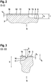
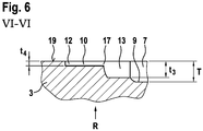
- the sipe 11 is formed along its extension between the circumferential groove 8 and kink 16 with a measured between the radially outer surface 19 and the sipe 11 radially inwardly delimiting Feininroughstress depth t 1 and along its extent in the first extension portion 14 between the Kink point 16 and the direction away from the kink point extension end of the first sipe 14 with a depth t 2 with t 2 ⁇ t 1 ⁇ T, where T indicates the depth of the circumferential groove 8.
- the sipe 10 is along its extension in the second extension portion 13 between the circumferential groove 7 and kink 17 with a depth t 3 and in its first extension portion 12 between kink 17 and the direction away from the kink point 17 extension end of the first extension portion 12 with a depth t 4 formed with t 4 ⁇ t 3 ⁇ T, where T indicates the depth of the circumferential grooves 7 and 8.
- the depths are 6mm ⁇ T ⁇ 8mm, 0.8T ⁇ t 1 ⁇ T, 0.1T ⁇ t 2 ⁇ 0.3T, 0.8T ⁇ t 3 ⁇ T and 0.1T ⁇ t 4 ⁇ 0.3T educated.
- T 7.5 mm
- t 1 6 mm
- t 2 1.5 mm
- t 3 6 mm
- t 4 1.5 mm.
- the sipes are formed with a reaching to the fine incision reason sizing width b with 0.4mm ⁇ b ⁇ 1mm.
- the sipe 10 of a pair of sipes 10 and 11 respectively extends with its first extension portion 12 within the circumferential extension portion of the first extension portion 14 of the sipe 11 of the pair.
- the sipe 10 extends with its entire circumferential extension length L 3 within the peripheral extension portion of Extension length L 2 of the first extension portion 14 of the sipe 11 of the pair.
- the fine incision 11 is bounded on either side of its sipe base each of a fine incision wall extending in the radial direction R, starting from the fine incision ground to the radially outer surface 19 of the circumferential rib 3.
- a chamfer 18 is formed in the transition of the sipe wall to the radially outer surface 19, which extends along the extension of the sipe 11 starting from the Circumferential groove 8 extends over the entire second extension portion 15 and over the kink 16 to the first extension portion 14 and ends there at a distance from its point away from the kink 16 extension end before reaching the extension end.
- the chamfer is formed in the first outgoing of the kink 16 extension region of the first extension portion 14 and in the subsequent, extending towards the end extension region is - as in FIG. 1 and 5 is shown - no bevel formed.
- the sipes 10 are formed free of chamfers along their entire extent.
- FIG. 1 shows a further embodiment of the circumferential rib 2, in which in an analogous manner pairs of sipes 10 'and 11' in the circumferential direction U are arranged one behind the other, which - as described above in connection with the sipes 10 and 11 - axially juxtaposed and each with a first extension portion 12 ', a kink 17' and a second extension portion 13 'or from a first extension portion 14', a kink 16 'and a second extension portion 15' are formed.
- FIG. 1 also shows the embodiment of the circumferential rib 2 an embodiment in which the orientation of the circumferential direction of the fine incision 11 'starting from the junction in the adjacent circumferential groove 7 along the extension of the first extension portion 15' via the kink 16 'and the subsequent second extension portion 14' opposite to the orientation of the circumferential extension direction of the adjacent sipe 10 'from its mouth into the adjacent circumferential groove 6 via the second extension portion 13', whose kink 17 'and its adjoining first extension portion 12' is aligned.
- FIG. 1 also shows on the basis of the embodiment in the circumferential rib 2, a further embodiment in which a chamfer 18 'only in the first extension portion 15' between the circumferential groove 7 and 16 'is formed and shortly before reaching the kink 16' ends.
- the first extension portion 14 ' is as well as the pointing to the shoulder outside fine sipe 10' of the circumferential rib 2 formed without chamfers.
- FIG. 1 also shows a further embodiment, in which the peripheral groove seen from the circumferential groove 7 to the vehicle inner side IN 3 - as described above or in the figures - with the pairs of sipes 10 and 11 and the circumferential groove 7 to the outside OU of the Vehicle arranged Circumferential rib 2 with - as described above or in the figures shown - formed pairs of sipes 10 'and 11' are formed.
Landscapes
- Engineering & Computer Science (AREA)
- Mechanical Engineering (AREA)
- Tires In General (AREA)
Applications Claiming Priority (1)
| Application Number | Priority Date | Filing Date | Title |
|---|---|---|---|
| DE102017207919.3A DE102017207919A1 (de) | 2017-05-10 | 2017-05-10 | Laufstreifenprofil eines Fahrzeugreifens |
Publications (2)
| Publication Number | Publication Date |
|---|---|
| EP3401125A1 true EP3401125A1 (fr) | 2018-11-14 |
| EP3401125B1 EP3401125B1 (fr) | 2020-01-29 |
Family
ID=61244440
Family Applications (1)
| Application Number | Title | Priority Date | Filing Date |
|---|---|---|---|
| EP18157339.5A Active EP3401125B1 (fr) | 2017-05-10 | 2018-02-19 | Profil de bande de roulement d'un pneu de véhicule |
Country Status (2)
| Country | Link |
|---|---|
| EP (1) | EP3401125B1 (fr) |
| DE (1) | DE102017207919A1 (fr) |
Cited By (1)
| Publication number | Priority date | Publication date | Assignee | Title |
|---|---|---|---|---|
| WO2020226017A1 (fr) * | 2019-05-08 | 2020-11-12 | 横浜ゴム株式会社 | Pneu |
Citations (2)
| Publication number | Priority date | Publication date | Assignee | Title |
|---|---|---|---|---|
| JP2011073471A (ja) * | 2009-09-29 | 2011-04-14 | Bridgestone Corp | 空気入りタイヤ |
| DE102012108384A1 (de) | 2012-09-10 | 2014-03-13 | Continental Reifen Deutschland Gmbh | Fahrzeugluftreifen |
-
2017
- 2017-05-10 DE DE102017207919.3A patent/DE102017207919A1/de not_active Withdrawn
-
2018
- 2018-02-19 EP EP18157339.5A patent/EP3401125B1/fr active Active
Patent Citations (2)
| Publication number | Priority date | Publication date | Assignee | Title |
|---|---|---|---|---|
| JP2011073471A (ja) * | 2009-09-29 | 2011-04-14 | Bridgestone Corp | 空気入りタイヤ |
| DE102012108384A1 (de) | 2012-09-10 | 2014-03-13 | Continental Reifen Deutschland Gmbh | Fahrzeugluftreifen |
Cited By (5)
| Publication number | Priority date | Publication date | Assignee | Title |
|---|---|---|---|---|
| WO2020226017A1 (fr) * | 2019-05-08 | 2020-11-12 | 横浜ゴム株式会社 | Pneu |
| JP2020183175A (ja) * | 2019-05-08 | 2020-11-12 | 横浜ゴム株式会社 | 空気入りタイヤ |
| JP7167840B2 (ja) | 2019-05-08 | 2022-11-09 | 横浜ゴム株式会社 | 空気入りタイヤ |
| DE112020001154B4 (de) * | 2019-05-08 | 2025-04-30 | The Yokohama Rubber Co., Ltd. | Luftreifen |
| US12508848B2 (en) | 2019-05-08 | 2025-12-30 | The Yokohama Rubber Co., Ltd. | Pneumatic tire |
Also Published As
| Publication number | Publication date |
|---|---|
| DE102017207919A1 (de) | 2018-11-15 |
| EP3401125B1 (fr) | 2020-01-29 |
Similar Documents
| Publication | Publication Date | Title |
|---|---|---|
| DE19753819B4 (de) | Laufflächenprofil eines Winterreifens | |
| EP2892736B1 (fr) | Pneumatique de véhicule | |
| DE102007061148A1 (de) | Fahrzeugluftreifen | |
| EP2636544B1 (fr) | Pneus de véhicule | |
| DE102015224288A1 (de) | Fahrzeugluftreifen | |
| EP3643527B1 (fr) | Pneumatiques de véhicule | |
| EP3204243B1 (fr) | Bandage pneumatique de véhicule | |
| EP3519208B1 (fr) | Pneumatique de véhicule | |
| EP3256335B1 (fr) | Pneumatique de véhicule | |
| DE102015224293A1 (de) | Fahrzeugluftreifen | |
| DE102019206654A1 (de) | Fahrzeugluftreifen | |
| DE202007019375U1 (de) | Fahrzeugluftreifen | |
| EP3538382B1 (fr) | Pneumatique | |
| EP3628511B1 (fr) | Pneumatiques de véhicule | |
| EP3401125B1 (fr) | Profil de bande de roulement d'un pneu de véhicule | |
| EP3160775B1 (fr) | Pneumatique de vehicule | |
| EP4173847B1 (fr) | Bandage pneumatique pour véhicule | |
| EP3560735B1 (fr) | Pneu de véhicule utilitaire | |
| DE102018216549A1 (de) | Fahrzeugluftreifen | |
| EP3890994B1 (fr) | Profil de bande de roulement d'un pneu de véhicule | |
| EP2914448B1 (fr) | Pneumatiques de véhicule | |
| DE102008029658A1 (de) | Fahrzeugluftreifen | |
| DE102004060793B3 (de) | Fahrzeugluftreifen | |
| DE102022204212A1 (de) | Fahrzeugluftreifen mit profiliertem Laufstreifen | |
| DE102022204215A1 (de) | Fahrzeugluftreifen mit profiliertem Laufstreifen |
Legal Events
| Date | Code | Title | Description |
|---|---|---|---|
| PUAI | Public reference made under article 153(3) epc to a published international application that has entered the european phase |
Free format text: ORIGINAL CODE: 0009012 |
|
| STAA | Information on the status of an ep patent application or granted ep patent |
Free format text: STATUS: THE APPLICATION HAS BEEN PUBLISHED |
|
| AK | Designated contracting states |
Kind code of ref document: A1 Designated state(s): AL AT BE BG CH CY CZ DE DK EE ES FI FR GB GR HR HU IE IS IT LI LT LU LV MC MK MT NL NO PL PT RO RS SE SI SK SM TR |
|
| AX | Request for extension of the european patent |
Extension state: BA ME |
|
| STAA | Information on the status of an ep patent application or granted ep patent |
Free format text: STATUS: REQUEST FOR EXAMINATION WAS MADE |
|
| 17P | Request for examination filed |
Effective date: 20190514 |
|
| RBV | Designated contracting states (corrected) |
Designated state(s): AL AT BE BG CH CY CZ DE DK EE ES FI FR GB GR HR HU IE IS IT LI LT LU LV MC MK MT NL NO PL PT RO RS SE SI SK SM TR |
|
| GRAP | Despatch of communication of intention to grant a patent |
Free format text: ORIGINAL CODE: EPIDOSNIGR1 |
|
| STAA | Information on the status of an ep patent application or granted ep patent |
Free format text: STATUS: GRANT OF PATENT IS INTENDED |
|
| INTG | Intention to grant announced |
Effective date: 20190920 |
|
| GRAS | Grant fee paid |
Free format text: ORIGINAL CODE: EPIDOSNIGR3 |
|
| GRAA | (expected) grant |
Free format text: ORIGINAL CODE: 0009210 |
|
| STAA | Information on the status of an ep patent application or granted ep patent |
Free format text: STATUS: THE PATENT HAS BEEN GRANTED |
|
| AK | Designated contracting states |
Kind code of ref document: B1 Designated state(s): AL AT BE BG CH CY CZ DE DK EE ES FI FR GB GR HR HU IE IS IT LI LT LU LV MC MK MT NL NO PL PT RO RS SE SI SK SM TR |
|
| REG | Reference to a national code |
Ref country code: GB Ref legal event code: FG4D Free format text: NOT ENGLISH |
|
| REG | Reference to a national code |
Ref country code: CH Ref legal event code: EP |
|
| REG | Reference to a national code |
Ref country code: AT Ref legal event code: REF Ref document number: 1228238 Country of ref document: AT Kind code of ref document: T Effective date: 20200215 |
|
| REG | Reference to a national code |
Ref country code: IE Ref legal event code: FG4D Free format text: LANGUAGE OF EP DOCUMENT: GERMAN |
|
| REG | Reference to a national code |
Ref country code: DE Ref legal event code: R096 Ref document number: 502018000677 Country of ref document: DE |
|
| REG | Reference to a national code |
Ref country code: NL Ref legal event code: MP Effective date: 20200129 |
|
| PG25 | Lapsed in a contracting state [announced via postgrant information from national office to epo] |
Ref country code: NO Free format text: LAPSE BECAUSE OF FAILURE TO SUBMIT A TRANSLATION OF THE DESCRIPTION OR TO PAY THE FEE WITHIN THE PRESCRIBED TIME-LIMIT Effective date: 20200429 Ref country code: FI Free format text: LAPSE BECAUSE OF FAILURE TO SUBMIT A TRANSLATION OF THE DESCRIPTION OR TO PAY THE FEE WITHIN THE PRESCRIBED TIME-LIMIT Effective date: 20200129 Ref country code: PT Free format text: LAPSE BECAUSE OF FAILURE TO SUBMIT A TRANSLATION OF THE DESCRIPTION OR TO PAY THE FEE WITHIN THE PRESCRIBED TIME-LIMIT Effective date: 20200621 Ref country code: RS Free format text: LAPSE BECAUSE OF FAILURE TO SUBMIT A TRANSLATION OF THE DESCRIPTION OR TO PAY THE FEE WITHIN THE PRESCRIBED TIME-LIMIT Effective date: 20200129 |
|
| REG | Reference to a national code |
Ref country code: LT Ref legal event code: MG4D |
|
| PG25 | Lapsed in a contracting state [announced via postgrant information from national office to epo] |
Ref country code: HR Free format text: LAPSE BECAUSE OF FAILURE TO SUBMIT A TRANSLATION OF THE DESCRIPTION OR TO PAY THE FEE WITHIN THE PRESCRIBED TIME-LIMIT Effective date: 20200129 Ref country code: GR Free format text: LAPSE BECAUSE OF FAILURE TO SUBMIT A TRANSLATION OF THE DESCRIPTION OR TO PAY THE FEE WITHIN THE PRESCRIBED TIME-LIMIT Effective date: 20200430 Ref country code: LV Free format text: LAPSE BECAUSE OF FAILURE TO SUBMIT A TRANSLATION OF THE DESCRIPTION OR TO PAY THE FEE WITHIN THE PRESCRIBED TIME-LIMIT Effective date: 20200129 Ref country code: IS Free format text: LAPSE BECAUSE OF FAILURE TO SUBMIT A TRANSLATION OF THE DESCRIPTION OR TO PAY THE FEE WITHIN THE PRESCRIBED TIME-LIMIT Effective date: 20200529 Ref country code: SE Free format text: LAPSE BECAUSE OF FAILURE TO SUBMIT A TRANSLATION OF THE DESCRIPTION OR TO PAY THE FEE WITHIN THE PRESCRIBED TIME-LIMIT Effective date: 20200129 Ref country code: BG Free format text: LAPSE BECAUSE OF FAILURE TO SUBMIT A TRANSLATION OF THE DESCRIPTION OR TO PAY THE FEE WITHIN THE PRESCRIBED TIME-LIMIT Effective date: 20200429 |
|
| PG25 | Lapsed in a contracting state [announced via postgrant information from national office to epo] |
Ref country code: NL Free format text: LAPSE BECAUSE OF FAILURE TO SUBMIT A TRANSLATION OF THE DESCRIPTION OR TO PAY THE FEE WITHIN THE PRESCRIBED TIME-LIMIT Effective date: 20200129 |
|
| REG | Reference to a national code |
Ref country code: BE Ref legal event code: MM Effective date: 20200229 |
|
| PG25 | Lapsed in a contracting state [announced via postgrant information from national office to epo] |
Ref country code: ES Free format text: LAPSE BECAUSE OF FAILURE TO SUBMIT A TRANSLATION OF THE DESCRIPTION OR TO PAY THE FEE WITHIN THE PRESCRIBED TIME-LIMIT Effective date: 20200129 Ref country code: CZ Free format text: LAPSE BECAUSE OF FAILURE TO SUBMIT A TRANSLATION OF THE DESCRIPTION OR TO PAY THE FEE WITHIN THE PRESCRIBED TIME-LIMIT Effective date: 20200129 Ref country code: LU Free format text: LAPSE BECAUSE OF NON-PAYMENT OF DUE FEES Effective date: 20200219 Ref country code: RO Free format text: LAPSE BECAUSE OF FAILURE TO SUBMIT A TRANSLATION OF THE DESCRIPTION OR TO PAY THE FEE WITHIN THE PRESCRIBED TIME-LIMIT Effective date: 20200129 Ref country code: SM Free format text: LAPSE BECAUSE OF FAILURE TO SUBMIT A TRANSLATION OF THE DESCRIPTION OR TO PAY THE FEE WITHIN THE PRESCRIBED TIME-LIMIT Effective date: 20200129 Ref country code: EE Free format text: LAPSE BECAUSE OF FAILURE TO SUBMIT A TRANSLATION OF THE DESCRIPTION OR TO PAY THE FEE WITHIN THE PRESCRIBED TIME-LIMIT Effective date: 20200129 Ref country code: LT Free format text: LAPSE BECAUSE OF FAILURE TO SUBMIT A TRANSLATION OF THE DESCRIPTION OR TO PAY THE FEE WITHIN THE PRESCRIBED TIME-LIMIT Effective date: 20200129 Ref country code: DK Free format text: LAPSE BECAUSE OF FAILURE TO SUBMIT A TRANSLATION OF THE DESCRIPTION OR TO PAY THE FEE WITHIN THE PRESCRIBED TIME-LIMIT Effective date: 20200129 Ref country code: SK Free format text: LAPSE BECAUSE OF FAILURE TO SUBMIT A TRANSLATION OF THE DESCRIPTION OR TO PAY THE FEE WITHIN THE PRESCRIBED TIME-LIMIT Effective date: 20200129 Ref country code: MC Free format text: LAPSE BECAUSE OF FAILURE TO SUBMIT A TRANSLATION OF THE DESCRIPTION OR TO PAY THE FEE WITHIN THE PRESCRIBED TIME-LIMIT Effective date: 20200129 |
|
| REG | Reference to a national code |
Ref country code: DE Ref legal event code: R097 Ref document number: 502018000677 Country of ref document: DE |
|
| PLBE | No opposition filed within time limit |
Free format text: ORIGINAL CODE: 0009261 |
|
| STAA | Information on the status of an ep patent application or granted ep patent |
Free format text: STATUS: NO OPPOSITION FILED WITHIN TIME LIMIT |
|
| RAP2 | Party data changed (patent owner data changed or rights of a patent transferred) |
Owner name: CONTINENTAL REIFEN DEUTSCHLAND GMBH |
|
| 26N | No opposition filed |
Effective date: 20201030 |
|
| PG25 | Lapsed in a contracting state [announced via postgrant information from national office to epo] |
Ref country code: IT Free format text: LAPSE BECAUSE OF FAILURE TO SUBMIT A TRANSLATION OF THE DESCRIPTION OR TO PAY THE FEE WITHIN THE PRESCRIBED TIME-LIMIT Effective date: 20200129 Ref country code: IE Free format text: LAPSE BECAUSE OF NON-PAYMENT OF DUE FEES Effective date: 20200219 |
|
| PG25 | Lapsed in a contracting state [announced via postgrant information from national office to epo] |
Ref country code: PL Free format text: LAPSE BECAUSE OF FAILURE TO SUBMIT A TRANSLATION OF THE DESCRIPTION OR TO PAY THE FEE WITHIN THE PRESCRIBED TIME-LIMIT Effective date: 20200129 Ref country code: SI Free format text: LAPSE BECAUSE OF FAILURE TO SUBMIT A TRANSLATION OF THE DESCRIPTION OR TO PAY THE FEE WITHIN THE PRESCRIBED TIME-LIMIT Effective date: 20200129 Ref country code: BE Free format text: LAPSE BECAUSE OF NON-PAYMENT OF DUE FEES Effective date: 20200229 |
|
| PG25 | Lapsed in a contracting state [announced via postgrant information from national office to epo] |
Ref country code: LI Free format text: LAPSE BECAUSE OF NON-PAYMENT OF DUE FEES Effective date: 20210228 Ref country code: CH Free format text: LAPSE BECAUSE OF NON-PAYMENT OF DUE FEES Effective date: 20210228 |
|
| PG25 | Lapsed in a contracting state [announced via postgrant information from national office to epo] |
Ref country code: TR Free format text: LAPSE BECAUSE OF FAILURE TO SUBMIT A TRANSLATION OF THE DESCRIPTION OR TO PAY THE FEE WITHIN THE PRESCRIBED TIME-LIMIT Effective date: 20200129 Ref country code: MT Free format text: LAPSE BECAUSE OF FAILURE TO SUBMIT A TRANSLATION OF THE DESCRIPTION OR TO PAY THE FEE WITHIN THE PRESCRIBED TIME-LIMIT Effective date: 20200129 Ref country code: CY Free format text: LAPSE BECAUSE OF FAILURE TO SUBMIT A TRANSLATION OF THE DESCRIPTION OR TO PAY THE FEE WITHIN THE PRESCRIBED TIME-LIMIT Effective date: 20200129 |
|
| PG25 | Lapsed in a contracting state [announced via postgrant information from national office to epo] |
Ref country code: MK Free format text: LAPSE BECAUSE OF FAILURE TO SUBMIT A TRANSLATION OF THE DESCRIPTION OR TO PAY THE FEE WITHIN THE PRESCRIBED TIME-LIMIT Effective date: 20200129 Ref country code: AL Free format text: LAPSE BECAUSE OF FAILURE TO SUBMIT A TRANSLATION OF THE DESCRIPTION OR TO PAY THE FEE WITHIN THE PRESCRIBED TIME-LIMIT Effective date: 20200129 |
|
| REG | Reference to a national code |
Ref country code: DE Ref legal event code: R081 Ref document number: 502018000677 Country of ref document: DE Owner name: CONTINENTAL REIFEN DEUTSCHLAND GMBH, DE Free format text: FORMER OWNER: CONTINENTAL REIFEN DEUTSCHLAND GMBH, 30165 HANNOVER, DE |
|
| REG | Reference to a national code |
Ref country code: AT Ref legal event code: MM01 Ref document number: 1228238 Country of ref document: AT Kind code of ref document: T Effective date: 20230219 |
|
| PG25 | Lapsed in a contracting state [announced via postgrant information from national office to epo] |
Ref country code: AT Free format text: LAPSE BECAUSE OF NON-PAYMENT OF DUE FEES Effective date: 20230219 |
|
| PG25 | Lapsed in a contracting state [announced via postgrant information from national office to epo] |
Ref country code: AT Free format text: LAPSE BECAUSE OF NON-PAYMENT OF DUE FEES Effective date: 20230219 |
|
| PGFP | Annual fee paid to national office [announced via postgrant information from national office to epo] |
Ref country code: GB Payment date: 20240219 Year of fee payment: 7 |
|
| GBPC | Gb: european patent ceased through non-payment of renewal fee |
Effective date: 20250219 |
|
| PG25 | Lapsed in a contracting state [announced via postgrant information from national office to epo] |
Ref country code: GB Free format text: LAPSE BECAUSE OF NON-PAYMENT OF DUE FEES Effective date: 20250219 |
|
| PGFP | Annual fee paid to national office [announced via postgrant information from national office to epo] |
Ref country code: DE Payment date: 20260228 Year of fee payment: 9 |
|
| PGFP | Annual fee paid to national office [announced via postgrant information from national office to epo] |
Ref country code: AT Payment date: 20260410 Year of fee payment: 5 |
|
| PGFP | Annual fee paid to national office [announced via postgrant information from national office to epo] |
Ref country code: FR Payment date: 20260218 Year of fee payment: 9 |