EP3401129A1 - Dispositif de mise en pression de pneu - Google Patents
Dispositif de mise en pression de pneu Download PDFInfo
- Publication number
- EP3401129A1 EP3401129A1 EP17170746.6A EP17170746A EP3401129A1 EP 3401129 A1 EP3401129 A1 EP 3401129A1 EP 17170746 A EP17170746 A EP 17170746A EP 3401129 A1 EP3401129 A1 EP 3401129A1
- Authority
- EP
- European Patent Office
- Prior art keywords
- check valve
- rim
- tire
- pressure
- section
- Prior art date
- Legal status (The legal status is an assumption and is not a legal conclusion. Google has not performed a legal analysis and makes no representation as to the accuracy of the status listed.)
- Granted
Links
Images


Classifications
-
- B—PERFORMING OPERATIONS; TRANSPORTING
- B60—VEHICLES IN GENERAL
- B60C—VEHICLE TYRES; TYRE INFLATION; TYRE CHANGING; CONNECTING VALVES TO INFLATABLE ELASTIC BODIES IN GENERAL; DEVICES OR ARRANGEMENTS RELATED TO TYRES
- B60C23/00—Devices for measuring, signalling, controlling, or distributing tyre pressure or temperature, specially adapted for mounting on vehicles; Arrangement of tyre inflating devices on vehicles, e.g. of pumps or of tanks; Tyre cooling arrangements
- B60C23/001—Devices for manually or automatically controlling or distributing tyre pressure whilst the vehicle is moving
- B60C23/003—Devices for manually or automatically controlling or distributing tyre pressure whilst the vehicle is moving comprising rotational joints between vehicle-mounted pressure sources and the tyres
- B60C23/00309—Devices for manually or automatically controlling or distributing tyre pressure whilst the vehicle is moving comprising rotational joints between vehicle-mounted pressure sources and the tyres characterised by the location of the components, e.g. valves, sealings, conduits or sensors
- B60C23/00336—Devices for manually or automatically controlling or distributing tyre pressure whilst the vehicle is moving comprising rotational joints between vehicle-mounted pressure sources and the tyres characterised by the location of the components, e.g. valves, sealings, conduits or sensors on the axles
-
- B—PERFORMING OPERATIONS; TRANSPORTING
- B60—VEHICLES IN GENERAL
- B60C—VEHICLE TYRES; TYRE INFLATION; TYRE CHANGING; CONNECTING VALVES TO INFLATABLE ELASTIC BODIES IN GENERAL; DEVICES OR ARRANGEMENTS RELATED TO TYRES
- B60C23/00—Devices for measuring, signalling, controlling, or distributing tyre pressure or temperature, specially adapted for mounting on vehicles; Arrangement of tyre inflating devices on vehicles, e.g. of pumps or of tanks; Tyre cooling arrangements
- B60C23/001—Devices for manually or automatically controlling or distributing tyre pressure whilst the vehicle is moving
- B60C23/003—Devices for manually or automatically controlling or distributing tyre pressure whilst the vehicle is moving comprising rotational joints between vehicle-mounted pressure sources and the tyres
- B60C23/00309—Devices for manually or automatically controlling or distributing tyre pressure whilst the vehicle is moving comprising rotational joints between vehicle-mounted pressure sources and the tyres characterised by the location of the components, e.g. valves, sealings, conduits or sensors
- B60C23/00318—Devices for manually or automatically controlling or distributing tyre pressure whilst the vehicle is moving comprising rotational joints between vehicle-mounted pressure sources and the tyres characterised by the location of the components, e.g. valves, sealings, conduits or sensors on the wheels or the hubs
-
- B—PERFORMING OPERATIONS; TRANSPORTING
- B60—VEHICLES IN GENERAL
- B60C—VEHICLE TYRES; TYRE INFLATION; TYRE CHANGING; CONNECTING VALVES TO INFLATABLE ELASTIC BODIES IN GENERAL; DEVICES OR ARRANGEMENTS RELATED TO TYRES
- B60C23/00—Devices for measuring, signalling, controlling, or distributing tyre pressure or temperature, specially adapted for mounting on vehicles; Arrangement of tyre inflating devices on vehicles, e.g. of pumps or of tanks; Tyre cooling arrangements
- B60C23/001—Devices for manually or automatically controlling or distributing tyre pressure whilst the vehicle is moving
- B60C23/003—Devices for manually or automatically controlling or distributing tyre pressure whilst the vehicle is moving comprising rotational joints between vehicle-mounted pressure sources and the tyres
- B60C23/00345—Details of the rotational joints
-
- B—PERFORMING OPERATIONS; TRANSPORTING
- B60—VEHICLES IN GENERAL
- B60C—VEHICLE TYRES; TYRE INFLATION; TYRE CHANGING; CONNECTING VALVES TO INFLATABLE ELASTIC BODIES IN GENERAL; DEVICES OR ARRANGEMENTS RELATED TO TYRES
- B60C23/00—Devices for measuring, signalling, controlling, or distributing tyre pressure or temperature, specially adapted for mounting on vehicles; Arrangement of tyre inflating devices on vehicles, e.g. of pumps or of tanks; Tyre cooling arrangements
- B60C23/001—Devices for manually or automatically controlling or distributing tyre pressure whilst the vehicle is moving
- B60C23/003—Devices for manually or automatically controlling or distributing tyre pressure whilst the vehicle is moving comprising rotational joints between vehicle-mounted pressure sources and the tyres
- B60C23/00354—Details of valves
-
- B—PERFORMING OPERATIONS; TRANSPORTING
- B60—VEHICLES IN GENERAL
- B60C—VEHICLE TYRES; TYRE INFLATION; TYRE CHANGING; CONNECTING VALVES TO INFLATABLE ELASTIC BODIES IN GENERAL; DEVICES OR ARRANGEMENTS RELATED TO TYRES
- B60C23/00—Devices for measuring, signalling, controlling, or distributing tyre pressure or temperature, specially adapted for mounting on vehicles; Arrangement of tyre inflating devices on vehicles, e.g. of pumps or of tanks; Tyre cooling arrangements
- B60C23/001—Devices for manually or automatically controlling or distributing tyre pressure whilst the vehicle is moving
- B60C23/003—Devices for manually or automatically controlling or distributing tyre pressure whilst the vehicle is moving comprising rotational joints between vehicle-mounted pressure sources and the tyres
- B60C23/00363—Details of sealings
Definitions
- Tire pressurizing devices are used in vehicles, in particular commercial vehicles, work vehicles or agricultural vehicles. Tire pressurizing devices serve to maintain a predetermined pressure or pressure range in a tire of the vehicle, for example also in the case of low leakage, temperature changes or changed loading of the vehicle. It is also possible that a tire pressure applying device specifically causes a change in the pressure in the tire, which can take place via a control or regulation. For example, a change in pressure in the tire may occur depending on a load of the vehicle and / or driving conditions, such as a speed of the vehicle. With a tire pressure application device according to the invention thus influencing the application of pressure to the tire, which can be done by venting, venting and / or shutting off the tire.
- Tire pressurizing devices of the present type are interposed between a non-rotating axle body, against which (directly or indirectly) the wheel is mounted, and a tire carrying the rotating rim, to the axle of a pressure source pending compressed air from the axle to the rim to transfer where the compressed air can reach into the limited by tires and a rim of the rim interior.
- a tire-pressurizing means via an axle body rotary feedthrough, which is connected via a hose or a pipe with a rim connecting element.
- the axle body rotary feedthrough has a stator which is fastened to the axle body.
- a rotor of the axle body rotary feedthrough is mounted rotatably relative to the stator.
- the rotor is attached to a rotating wheel body, such as the rim, so that this with the rolling of the wheel relative to the Stator is relatively twisted.
- the rotor is sealed from the stator so that pressurized air from an input port of the stator can be transmitted to the rotor while sealing outward from the rotor with respect to the stator, and then from an output port of the rotor to the hose connected to the output port or tube to arrive.
- the hose or tube is connected in the other end region to an input port of the rim connection element.
- the rim connection element is attached to the rim (in particular on a radially inner surface of the rim bed).
- the compressed air (in particular via a suitable recess or bore of the rim bed) reaches the interior space bounded by the rim base and the tire.
- the axle body rotary feedthrough and the rim connection element have suitable valve elements, for example, to influence the admission of the tire and / or to avoid an undesired escape of compressed air during assembly of the tire pressure application device.
- the publication DE 20 2007 017 617 U1 discloses a tire pressurizing device in which the stator of the axle body rotary union is held on the vehicle side while the rotor is fixed to a rotating hub to which the rim of the wheel is fixed. From the rotor extends both a conduit for supplying compressed air to the tire and a control line to a valve unit.
- the valve unit is attached to the radially inwardly facing bottom of the rim base of the rim. Via a pneumatic control of the pressure in the control line, a valve of the valve unit can be controlled so that the admission of pressure to the tire can be changed.
- the valve unit has a pressure sensor which communicates via a transmitter with a vehicle-side control device.
- the tire pressure application device has a rim connection element for a variant.
- the rim connector has an input port.
- the inlet connection can be coupled with a pipe or a hose.
- the rim connection element has an output connection which can be coupled to a rim (in particular a rim base of the rim).
- the rim connection element has a mechanical actuating element.
- the mechanical actuating element protrudes into a coupling region of the rim connecting element in such a way that the mechanical actuating element is actuated in a motion-controlled manner with a (direct or indirect) connection to the rim.
- the movement-controlled actuation of the mechanical actuating element has the consequence that a check valve of the rim connection element is opened.
- the rim connection element additionally has a check valve.
- This is preferably not spring-loaded, so that this opens at a very small pressure difference between the input and output side of the check valve.
- the check valve is in this case arranged so that this allows a flow of compressed air from the input terminal of the rim connecting element to the output terminal and thus to the interior of the tire, while the check valve an opposite flow of compressed air, which would cause a venting of the tire, in derogation.
- the check valve is preferably arranged between the check valve and the inlet connection of the rim connection element.
- the check valve and the check valve are arranged in fluidic series connection between the input terminal and the output terminal of the rim terminal element.
- the fluidic series connection of the check valve and the check valve has the consequence that two different functions can be reliably ensured: On the one hand, the check valve ensures that a fluid connection of the output terminal to the input terminal of the rim connection element can only take place, although the rim connection element mechanically coupled to the rim. Thus, for not coupled with the rim rim connection element undesirable escape of compressed air from the rim connection element can be avoided.
- the check valve ensures that at a pressure applied to the input port of the rim connecting element, which is greater when the pressure at the outlet port of the rim fitting is greater than the pressure in the interior of the tire, it is possible to add pressurized air to the tire via the tire pressurization device. If the check valve is not designed with an increased opening pressure and in particular not spring-loaded, u. For example, there may be no or reduced variations in the opening pressures of tire pressurizing devices on different wheels of the vehicle when supplied to them via a common central conduit which could result in undesirable differential pressurizations of the different tires.
- both a rim terminal and an axle body rotary joint as described above are used, thus also cumulatively achieving the above-described functions and effects.
- the actuating element of the rim connecting element also forms a stop for a check valve body of the check valve, so that the actuating element can be used multifunctionally.
- the stop defines an open position of the check valve body relative to a check valve seat. In this case, the stop does not take a fixed relative position relative to the housing the rim connection element and the check valve seat, but this changes with the movement of the actuating element.
- the check valve seat of the check valve is formed by a housing of the rim connection element.
- the check valve body is guided in an inner bore or recess of the housing or an inner bore or recess of a sleeve inserted into the housing so that the check valve body can move relative to the check valve seat between an open position and a closed position.
- This can result in any crossover cross section between the check valve body and the sleeve or the housing.
- a crossover cross section in the form of an annular gap is formed between the inner bore or recess of the housing or the sleeve and the check valve body.
- the rim connecting element has a sleeve which is inserted into a recess of a first housing part. Through this sleeve, the actuating element extends. Another sleeve is also inserted into the recess of the first housing part. In this further sleeve, the check valve body is guided so that the check valve body can move relative to the check valve seat between an open position and a closed position. In this case, the further sleeve is arranged adjacent to the check valve seat.
- the actuating element forms the check valve body in the form of a blocking valve disk. The check valve body is arranged axially between the two sleeves in this case.
- the check valve body is movable in the further sleeve between the check valve seat and a stop, wherein the stop is formed by the actuating element.
- the recess is connected via a preferably radially extending from the recess to the lateral surface extending channel with a lateral surface of the first housing part.
- the first housing part is inserted into a recess, in particular bore, of a second housing part. Between the two housing parts, an annular space is formed, in which the outgoing from the recess channel opens. Via another channel, the annular space is connected to the input terminal of the rim connection element.
- the first crossing cross-section is formed by a (arbitrarily shaped, in particular graduated) through-bore of a valve body of the pressure-securing valve.
- the second crossover cross section is formed by an annular gap, which is bounded radially inwardly by the valve body of the pressure relief valve, while the annular gap is bounded radially outwardly by a recess of a housing or an insert of the housing of the axle body rotary union.
- the two crossing cross-sections can merge into one another, so that in the open position of the pressure-securing valve, a continuous cross-sectional cross-sectional area is formed by the two crossing cross-sections.
- the crossing cross-sectional area decreases with the closure of the pressure-securing valve to the cross-sectional area of the first crossover cross section.
- the valve body of the pressure relief valve which defines the annular gap lying inside, have a radial recess or an outer channel, so that in the closed position of the valve body basically the annular gap is closed, but on the first crossing cross-section forming channel or the recess in the closed position of the pressure relief valve still allows a residual flow of compressed air.
- the first crossing cross-section there are many possibilities with regard to the cross-sectional area of the cross-section as well as the contour of the cross-section in the flow direction.
- the first crossing cross-section is smaller by a factor of 5, 10, 20, 50 or even 100 than the second crossing cross-section.
- the first crossover cross section is formed by a throttle bore, which may also be formed as a stepped throttle bore.
- the pressure-securing valve can have any opening and / or closing characteristic.
- the pressure relief valve has a switching hysteresis, whereby a particularly reliable guarantee of the pressure relief and under certain circumstances, a rapid induction of an open position of the pressure relief valve and / or the reliable maintenance thereof can take place.
- the design of the crossover cross sections and throttle characteristics of the rim connection element and the axle body rotary feedthrough can be basically arbitrary.
- an overall throttle effect of the rim connection element is greater than an overall throttle effect of the axle body rotary feedthrough.
- This embodiment of the invention may be based, for example, on the recognition that the closure of the pressure-securing valve of the axle body rotary union is to be ensured for a demolition of the hose while the pressure-securing valve of the axle body rotary union is to assume or maintain its open position when the tire is empty or only with a small pressure is applied.
- the pressure relief valve can assume its closed position.
- the total throttle effect of the rim connection element more than 40%, more than 50% or more than 60% greater than the total throttle effect of the body rotary feedthrough. It is also possible that an opening or crossover cross section of the check valve of the rim connection element is more than 40%, more than 50% or more than 60% smaller than the second crossing cross section of the axle body rotary feedthrough.
- the tire pressurizing device is designed as a tire refilling device, by means of which a constant tire pressure is ensured by a replenishment of compressed air in the tire takes place in a natural, possibly minor and / or slow leakage.
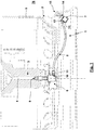
- Fig. 1 is a tire-pressurizing device 1 in an exemplary selected installation environment, here shown with a dashed rim 2 and a not rotating with the rim 2 axle body 3, shown.
- the tire pressure application device 1 can also be used in any other installation environments (cf., the prior art cited in the introduction, which is the subject of the present application), provided that any configured, not rotating rim 2 Axle body is present.
- the rim possibly via a suitable hub and with the interposition of bearings, rotatably mounted in a conventional manner.
- the axle body 3 has a channel or a line 4.
- compressed air which for filling an interior 76, which of a rim 5 of the rim 2 and a in Fig. 1 is not shown, mounted with the rim 2 tires limited is determined.
- This compressed air comes from a compressed air source of the vehicle.
- a compressed air system of the vehicle may have a compressed air treatment device, via which several circuits (such as service brake circuits, air suspension circuit, Mautile Drucke u. ⁇ .) With compressed air (possibly with different operating pressures) are supplied with a circle then for the supply of the wheels Compressed air is determined.
- lines 4 for different wheels, wheels on different axes or wheels on different sides via common or different lines with the same or different pressures can be applied.
- this connection has, on the one hand, a mechanical connection in order to connect the connected components mechanically to one another, in particular to fasten them to one another.
- a connection also forms a pneumatic connection, by means of which (with sealing against the environment) a transfer of compressed air between the components connected to one another is made possible.
- the tire pressure application device 1 has three structural units, namely an axle body rotary union 6, a rim connection element 7 and a hose 8, via which the axle body rotary union 6 is pneumatically connected to the rim connection element 7 and via which the distance between the Axle body rotary union 6 and the rim connecting element 7 is bridged.
- the axle body rotary feedthrough 6 has an input connection 9, via which the axle body rotary feedthrough 6 is mechanically connected to the axle body 3 and communicates pneumatically with the channel 4. Furthermore, the axle body rotary feedthrough 6 has an output connection 10, via which the axle body rotary feedthrough is mechanically connected to the hose 8, namely with a hose clamp or hose connection 11 or a union nut 75, and the axle body rotary union 6 also pneumatically with the hose 8 communicates.
- the rim connection element 7 has an input connection 12, via which it is mechanically connected, in this case by means of a hose connection or hose clamp 13 or union nut 67, to the hose 8 and communicates pneumatically with the hose 8. Furthermore, the rim connecting element 7 has an output terminal 14, via which the rim connecting element 7 is connected mechanically, here indirectly via a coupling body 15, to the rim 2 in the region of the rim bed 5 and pneumatically, here by the coupling body 15 and a Recess of the rim base 5 through, communicates with the space defined by the rim 5 and the tire inner space 76.
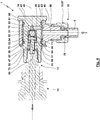
- Fig. 2 shows an axle body rotary feedthrough 6 in a longitudinal section.
- the axle body rotary feedthrough 6 has a stator 16 which is arranged coaxially to a longitudinal axis 17 of the axle body 3, which corresponds to the axis of rotation of the rim 2.
- the input terminal 9 of the axle body rotary feedthrough 6 in the axial body 3 facing end portion of the stator 16 has an external thread 18.
- a rotor 21 is rotatably mounted on the stator 16 about the longitudinal axis 17 via a bearing 19, in this case a rolling bearing 20.
- the stator 16 is elongated, for example, rod-like with a stepped longitudinal section and circular cross-sections, and has a recess 22 continuous in the direction of the longitudinal axis 17, which is formed as a stepped bore whose diameter is reduced in steps in the direction of the rotor 21.
- the recess 22 forms an inlet chamber 23, through which a filter element 24 extends.
- the filter element 24 is formed as a filter disc, which is supported in a direction of the longitudinal axis 17 at a shoulder of the stator 16, while this is secured in the other direction by a locking ring.
- the inlet chamber 23 merges via a conical valve seat 25 into a guide bore 26 whose diameter is smaller than the diameter of the inlet chamber 23.
- a valve body 27 which, in a first approximation, is T-shaped in longitudinal section or mushroom-shaped.
- the transverse leg of the T forms a valve body plate 28, which is arranged in the inlet chamber 23.
- the vertical leg of the T forms a guide sleeve 29, which is slidably guided in the guide bore 26.
- a spring 30 is supported, which extends through the guide sleeve 29 and in which the valve body plate 28 facing away from end portion is supported on a shoulder of the recess 22.
- a recess 31 extends through the valve body 27, which thus provides a first crossover cross section 32.
- the recess 31 is in this case formed with a throttle bore 33, which extends from the input terminal 9 facing the end face of the valve body 27 and opens into the inner bore of the guide sleeve 29.
- an annular gap 35 is formed, which provides a second crossing cross-section 36.
- the valve body plate 28 On the side facing the valve seat 25 formed by the housing 34, the valve body plate 28 has a sealing element 37, which is designed here as a sealing ring, but can also be designed as a sealing coating of the valve body plate 28.
- the valve body 27 is displaceable axially in the direction of the longitudinal axis 17 between an open position according to Fig. 2 and a closed position according to Fig. 3 , in this connection the valve body 27 is acted on on the side facing the input port 9 with the pressure applied to the input port, resulting in a pressure force which acts in the direction of the closed position.
- a compressive force which is generated due to the pressure at the output terminal 10 to the predetermined by the cross-sectional area of the guide sleeve 29 effective surface of the valve body 27, and on the other hand, the pressing force of the spring 30.
- a dimensioning of the surfaces the valve body 27, which are exposed to said pressures, as well as the spring 30 is such that for a sufficiently large pressure at the output port 10, the pressure force due to this pressure and the force of the spring 30 outweigh the pressure force which the pressure at the input port 9 generated on the valve body 27.
- the valve body 27 is in the in Fig. 2 illustrated opening position. If, on the other hand, the pressure at the outlet connection 10 breaks as a result of a leakage of the tube 8 or a break therefrom, the compressive force generated by this pressure on the valve body 27 is reduced. This pressure force and the force of the spring 30 are then smaller than the pressure force which is generated by the pressure at the input port 9 to the valve body 27, whereby a movement of the valve body 27 in the in Fig. 3 effective closed position takes place.
- compressed air supplied to the inlet connection 9 is divided into two partial streams after flowing through the filter element 24.
- a first partial flow flows through the recess 31 with the first crossover cross section 32 and the throttle bore 33, then flows through the inner bore of the guide sleeve 29 with then further flow through the stator 16.
- a second partial flow flows through the annular gap 35 and from On the side facing away from the valve body plate 28 side of this partial flow passes through a transverse bore 38 into the interior of the guide sleeve 29, from where this partial flow can flow through the stator 16 on. In the interior of the guide sleeve 29 thus unite the two streams again.
- a pressure relief valve 39 is formed. This permits a flow of compressed air to the tire through the axle body rotary leadthrough 6 if a sufficient pressure is applied in the region of the outlet connection 10, while for a defect or a demolition of the hose 8 a pressure protection takes place in that the pressure-securing valve 39 assumes its closed position , Which avoids that (except for a desired, but limited residual flow, which flows through the first crossover cross section 32) further compressed air flows through the axle body rotary union 6 and flows over the torn or defective hose 8 into the environment.
- the recess 22 opens under sealing by a sealing element 40, which is braced between a lateral surface of the end region of the stator 16 and an inner surface of a housing 41 of the rotor 21, into an outlet chamber 42 formed by the housing 41
- Output chamber 42 is pneumatically connected to output port 10.
- a connecting piece 43 is screwed to the output chamber 42, which is penetrated by a stepped through bore 44.
- the connecting piece 43 has a jacket surface 77 that widens conically, for example, onto which the hose 8 can be pushed with elastic and / or plastic widening. In this deferred state of the hose 8 via the hose connection 11 or a union nut 75, which is screwed with a thread of the connecting piece 43, are secured.
- a rim connecting element 7 is shown cut in solid lines, while in the Fig. 4 and 5 a coupling body 15, on which here the rim connecting element 7 is mounted, dashed and shown with a smaller line thickness.
- the rim connecting element 7 has two housing parts 45, 46.
- the housing part 45 has a blind hole-like recess 47, which is oriented in the direction of a longitudinal axis 48.
- a transverse to the longitudinal axis 48 oriented, emanating from the lateral surface of the housing part 45 transverse bore or a channel 49.
- Adjacent to the junction of the transverse bore 49 in the recess 47 forms a cone-shaped here enlargement of the cross section a check valve seat 50 , At a the check valve seat 50 adjacent shoulder of the recess 47, a sleeve 51 is supported.
- a check valve body 53 axially guided in the direction of the longitudinal axis 48.
- the check valve body 53 is formed as a ball 54.
- an actuating element 55 On the side facing away from the check valve seat 50 side of the check valve body 53 extends in the recess 47, an actuating element 55.
- the actuator 55 is formed in a first approximation corresponding to a lying T, wherein the vertical leg of the lying T is disposed on the check valve body 53 facing side.
- the vertical leg of the T forms a check valve body 56, which may be provided on the side facing away from the check valve body 53 with a sealing element 57 or a sealing coating.
- the horizontal leg of the lying T of the actuator 55 extends through a sleeve 58 and protrudes from the output terminal 14 or into it, so that the end portion of the actuator 55 can interact with the coupling body 15.
- the blocking valve body 56 facing end face of the sleeve 58 forms a check valve seat 59.
- the housing part 45 is inserted into a through-passage 60 of the housing part 46.
- the housing part 45 is caught in the through-hole 60 between a shoulder 61 of the housing part 46 and a retaining ring 62 held on the housing part 45.
- Between the housing parts 45, 46 results in an annular space 63 which is sealed by sealing elements 64, 65 to the outside.
- the transverse bore 49 of the housing part 45 opens into the annular space 63.
- a bore or a channel 66 of the housing part 46 which opens into the inlet connection 12, opens into the annular space 63.
- the input terminal 12 has a cone-shaped connection surface 78 here, on which the hose 8 can be pushed under elastic or plastic widening.
- a securing of the hose 8 to the housing part 46 in such a deferred state takes place in that on the housing part 45, a hose connection 13 or a cap nut 67 is screwed with a clamping of the tube 8 between the pad 78 and the cap nut 67th
- the actuating element 55 forms a stop 71 from.
- the check valve body 53 has limited mobility in the direction of the longitudinal axis 48. If a greater pressure is applied to the input port 12 of the rim connection element 7 than at the output port 14 (and preferably as in the tire), the throttling of the flow of compressed air in the region of the annular gap 52 causes on the side facing the input port 12 of the check valve body 53 with a greater pressure is applied than on the output terminal 14 side facing. This has the consequence that the check valve body 53, the in Fig. 4 takes effective position in which it rests against the stop 71 and spaced from the check valve seat 50 is arranged.
- the rim connecting element 7 of the rim 2, here the coupling body 15, disassembled, the output port 14 is depressurized, while for a via the axle body rotary feedthrough 6 coupled to a pressure source of an axle body 3 hose, the input port 12 is pressurized.
- the check valve body 53 is acted upon in the direction of the outlet port 14, so that it can move away from the check valve seat 50.
- the check valve body 53 comes into abutment against the stop 71 of the actuating element 55.
Landscapes
- Engineering & Computer Science (AREA)
- Mechanical Engineering (AREA)
- Check Valves (AREA)
- Tires In General (AREA)
Priority Applications (3)
| Application Number | Priority Date | Filing Date | Title |
|---|---|---|---|
| EP17170746.6A EP3401129B1 (fr) | 2017-05-12 | 2017-05-12 | Dispositif de mise en pression de pneu |
| ES17170746T ES2745326T3 (es) | 2017-05-12 | 2017-05-12 | Equipo de presurización para neumáticos |
| PL17170746T PL3401129T3 (pl) | 2017-05-12 | 2017-05-12 | Urządzenie do zapewniania ciśnienia w oponach |
Applications Claiming Priority (1)
| Application Number | Priority Date | Filing Date | Title |
|---|---|---|---|
| EP17170746.6A EP3401129B1 (fr) | 2017-05-12 | 2017-05-12 | Dispositif de mise en pression de pneu |
Publications (2)
| Publication Number | Publication Date |
|---|---|
| EP3401129A1 true EP3401129A1 (fr) | 2018-11-14 |
| EP3401129B1 EP3401129B1 (fr) | 2019-06-12 |
Family
ID=58707368
Family Applications (1)
| Application Number | Title | Priority Date | Filing Date |
|---|---|---|---|
| EP17170746.6A Active EP3401129B1 (fr) | 2017-05-12 | 2017-05-12 | Dispositif de mise en pression de pneu |
Country Status (3)
| Country | Link |
|---|---|
| EP (1) | EP3401129B1 (fr) |
| ES (1) | ES2745326T3 (fr) |
| PL (1) | PL3401129T3 (fr) |
Cited By (3)
| Publication number | Priority date | Publication date | Assignee | Title |
|---|---|---|---|---|
| WO2021030486A1 (fr) * | 2019-08-12 | 2021-02-18 | Equalaire Systems, Inc. | Raccord rotatif à position réglable |
| DE102021000192B3 (de) | 2021-01-18 | 2022-04-28 | Markus Rottmann | Kompakter Drehübertrager oder Drehdurchführung |
| DE102021122133A1 (de) | 2021-08-26 | 2023-03-02 | Saf-Holland Gmbh | Nabenkappensystem für ein Fahrzeug |
Families Citing this family (1)
| Publication number | Priority date | Publication date | Assignee | Title |
|---|---|---|---|---|
| EP4375092B1 (fr) | 2022-11-24 | 2024-12-04 | Reinhold Schulte | Ensemble valve de pression de pneu et groupe comprenant des ensembles valve de pression de pneu |
Citations (13)
| Publication number | Priority date | Publication date | Assignee | Title |
|---|---|---|---|---|
| GB659582A (en) * | 1948-12-22 | 1951-10-24 | Amilcare Vignini | Method and means for checking and adjusting the air pressure in tyres |
| US4804027A (en) * | 1987-09-17 | 1989-02-14 | Eaton Corporation | Axle and wheel assembly |
| DE19950191C1 (de) | 1999-10-19 | 2001-05-10 | Tigges & Winckel Bonumwerke | Reifendruckregelanlage |
| CN2614959Y (zh) * | 2003-03-31 | 2004-05-12 | 大捷达实业(深圳)有限公司 | 可调控气压的轮胎充气连接器 |
| DE102005018584A1 (de) | 2005-04-21 | 2006-10-26 | Deere & Company, Moline | Vorrichtung, insbesondere Drehdurchführung |
| KR20080037512A (ko) * | 2006-10-26 | 2008-04-30 | 금호타이어 주식회사 | 타이어 공기압 조절용 로터리 밸브 |
| DE202007017617U1 (de) | 2007-12-14 | 2009-04-16 | PTG Pösges & Tigges GmbH | Reifendruckregelanlage |
| DE202011051737U1 (de) | 2011-10-24 | 2011-11-04 | Ptg Reifendruckregelsysteme Gmbh | Drehdurchführung als Teil einer Reifendruckregelanlage eines Fahrzeuges |
| EP2613950B1 (fr) | 2010-09-06 | 2014-08-13 | PTG Reifendruckregelsysteme GmbH | Système de régulation de la pression des pneus présentant un passage tournant |
| DE102014117459A1 (de) | 2014-03-11 | 2015-09-17 | Klemens Große-Vehne | Druckmittelversorgungseinrichtung, Radeinheit mit einer Druckmittelversorgungseinrichtung sowie verteiltes System zur Druckmittelversorgung |
| WO2016090218A1 (fr) * | 2014-12-04 | 2016-06-09 | Dana Heavy Vehicle Systems Group, Llc | Système de gestion de pression de pneu |
| EP2952365B1 (fr) | 2014-06-06 | 2016-12-14 | Kessler & Co. GmbH & Co. KG | Passage tournant pour roue de véhicule |
| DE202015105702U1 (de) | 2015-10-27 | 2017-01-30 | Ptg Reifendruckregelsysteme Gmbh | Drehdurchführung einer Reifendruckregelanlage sowie Anordnung umfassend eine solche Drehdurchführung sowie eine auf einem Achsstummel gelagerte Nabe |
-
2017
- 2017-05-12 PL PL17170746T patent/PL3401129T3/pl unknown
- 2017-05-12 EP EP17170746.6A patent/EP3401129B1/fr active Active
- 2017-05-12 ES ES17170746T patent/ES2745326T3/es active Active
Patent Citations (13)
| Publication number | Priority date | Publication date | Assignee | Title |
|---|---|---|---|---|
| GB659582A (en) * | 1948-12-22 | 1951-10-24 | Amilcare Vignini | Method and means for checking and adjusting the air pressure in tyres |
| US4804027A (en) * | 1987-09-17 | 1989-02-14 | Eaton Corporation | Axle and wheel assembly |
| DE19950191C1 (de) | 1999-10-19 | 2001-05-10 | Tigges & Winckel Bonumwerke | Reifendruckregelanlage |
| CN2614959Y (zh) * | 2003-03-31 | 2004-05-12 | 大捷达实业(深圳)有限公司 | 可调控气压的轮胎充气连接器 |
| DE102005018584A1 (de) | 2005-04-21 | 2006-10-26 | Deere & Company, Moline | Vorrichtung, insbesondere Drehdurchführung |
| KR20080037512A (ko) * | 2006-10-26 | 2008-04-30 | 금호타이어 주식회사 | 타이어 공기압 조절용 로터리 밸브 |
| DE202007017617U1 (de) | 2007-12-14 | 2009-04-16 | PTG Pösges & Tigges GmbH | Reifendruckregelanlage |
| EP2613950B1 (fr) | 2010-09-06 | 2014-08-13 | PTG Reifendruckregelsysteme GmbH | Système de régulation de la pression des pneus présentant un passage tournant |
| DE202011051737U1 (de) | 2011-10-24 | 2011-11-04 | Ptg Reifendruckregelsysteme Gmbh | Drehdurchführung als Teil einer Reifendruckregelanlage eines Fahrzeuges |
| DE102014117459A1 (de) | 2014-03-11 | 2015-09-17 | Klemens Große-Vehne | Druckmittelversorgungseinrichtung, Radeinheit mit einer Druckmittelversorgungseinrichtung sowie verteiltes System zur Druckmittelversorgung |
| EP2952365B1 (fr) | 2014-06-06 | 2016-12-14 | Kessler & Co. GmbH & Co. KG | Passage tournant pour roue de véhicule |
| WO2016090218A1 (fr) * | 2014-12-04 | 2016-06-09 | Dana Heavy Vehicle Systems Group, Llc | Système de gestion de pression de pneu |
| DE202015105702U1 (de) | 2015-10-27 | 2017-01-30 | Ptg Reifendruckregelsysteme Gmbh | Drehdurchführung einer Reifendruckregelanlage sowie Anordnung umfassend eine solche Drehdurchführung sowie eine auf einem Achsstummel gelagerte Nabe |
Cited By (4)
| Publication number | Priority date | Publication date | Assignee | Title |
|---|---|---|---|---|
| WO2021030486A1 (fr) * | 2019-08-12 | 2021-02-18 | Equalaire Systems, Inc. | Raccord rotatif à position réglable |
| DE102021000192B3 (de) | 2021-01-18 | 2022-04-28 | Markus Rottmann | Kompakter Drehübertrager oder Drehdurchführung |
| DE102021122133A1 (de) | 2021-08-26 | 2023-03-02 | Saf-Holland Gmbh | Nabenkappensystem für ein Fahrzeug |
| DE102021122133B4 (de) | 2021-08-26 | 2023-10-26 | Saf-Holland Gmbh | Nabenkappensystem für ein Fahrzeug |
Also Published As
| Publication number | Publication date |
|---|---|
| PL3401129T3 (pl) | 2019-12-31 |
| EP3401129B1 (fr) | 2019-06-12 |
| ES2745326T3 (es) | 2020-02-28 |
Similar Documents
| Publication | Publication Date | Title |
|---|---|---|
| EP2475562B1 (fr) | Dispositif de valve-relais | |
| EP3371018B1 (fr) | Soupape de limitation de pression | |
| EP0726190B1 (fr) | Installation de freinage actionnée par pression pour véhicules | |
| EP3401129B1 (fr) | Dispositif de mise en pression de pneu | |
| EP3371019B1 (fr) | Soupape de limitation de pression | |
| EP2193282A1 (fr) | Elément hydraulique | |
| EP2058193A2 (fr) | Soupape pouvant être entraînée manuellement pour une installation de frein d'une remorque | |
| WO2008080945A1 (fr) | Dispositif de contrôle de pression pour un véhicule | |
| DE2520889A1 (de) | Zweiwegeabsperrventil, insbesondere fuer pneumatische kraftfahrzeugbremsanlagen | |
| WO2011104148A1 (fr) | Valve de pneumatique | |
| EP2551568B1 (fr) | Dispositif de vanne d'arrêt automatique | |
| EP3515767B1 (fr) | Soupape de régulation de pression d'un système de traitement d'air dans un véhicule utilitaire | |
| EP3259162A1 (fr) | Servofrein à dépression muni d'un système de soupape de commande d'étranglement | |
| DE3001001C2 (de) | Zweikreisbremssystem für Kraftfahrzeuge | |
| EP3290280B1 (fr) | Pluralité de valves-relais ainsi que système de freinage pneumatique pourvu d'au moins une pluralité de valves-relais | |
| EP4375092B1 (fr) | Ensemble valve de pression de pneu et groupe comprenant des ensembles valve de pression de pneu | |
| DE102018002488B4 (de) | Bremssystem eines Fahrzeugzuges | |
| WO2020144213A1 (fr) | Soupape à sièges | |
| DE2213463A1 (de) | Bremssteuervorrichtung | |
| WO2024132242A1 (fr) | Soupape de retenue de pression résiduelle pour un ressort à pression de gaz | |
| DE2527775A1 (de) | Mehrkreisschutzventil fuer pneumatische bremsanlagen an kraftfahrzeugen | |
| EP3121075B1 (fr) | Soupape a dechirement | |
| DE102009043568A1 (de) | Sicherheitsventil | |
| EP1410969B1 (fr) | Dispositif de commutation d'une soupape de freinage de remorque | |
| DE2106849A1 (de) | Druckmittelbetatigte Bremsvor richtung |
Legal Events
| Date | Code | Title | Description |
|---|---|---|---|
| PUAI | Public reference made under article 153(3) epc to a published international application that has entered the european phase |
Free format text: ORIGINAL CODE: 0009012 |
|
| STAA | Information on the status of an ep patent application or granted ep patent |
Free format text: STATUS: REQUEST FOR EXAMINATION WAS MADE |
|
| 17P | Request for examination filed |
Effective date: 20180725 |
|
| AK | Designated contracting states |
Kind code of ref document: A1 Designated state(s): AL AT BE BG CH CY CZ DE DK EE ES FI FR GB GR HR HU IE IS IT LI LT LU LV MC MK MT NL NO PL PT RO RS SE SI SK SM TR |
|
| AX | Request for extension of the european patent |
Extension state: BA ME |
|
| GRAP | Despatch of communication of intention to grant a patent |
Free format text: ORIGINAL CODE: EPIDOSNIGR1 |
|
| STAA | Information on the status of an ep patent application or granted ep patent |
Free format text: STATUS: GRANT OF PATENT IS INTENDED |
|
| INTG | Intention to grant announced |
Effective date: 20190102 |
|
| GRAS | Grant fee paid |
Free format text: ORIGINAL CODE: EPIDOSNIGR3 |
|
| GRAA | (expected) grant |
Free format text: ORIGINAL CODE: 0009210 |
|
| STAA | Information on the status of an ep patent application or granted ep patent |
Free format text: STATUS: THE PATENT HAS BEEN GRANTED |
|
| AK | Designated contracting states |
Kind code of ref document: B1 Designated state(s): AL AT BE BG CH CY CZ DE DK EE ES FI FR GB GR HR HU IE IS IT LI LT LU LV MC MK MT NL NO PL PT RO RS SE SI SK SM TR |
|
| REG | Reference to a national code |
Ref country code: GB Ref legal event code: FG4D Free format text: NOT ENGLISH |
|
| REG | Reference to a national code |
Ref country code: CH Ref legal event code: EP |
|
| REG | Reference to a national code |
Ref country code: AT Ref legal event code: REF Ref document number: 1142097 Country of ref document: AT Kind code of ref document: T Effective date: 20190615 |
|
| REG | Reference to a national code |
Ref country code: DE Ref legal event code: R096 Ref document number: 502017001524 Country of ref document: DE |
|
| REG | Reference to a national code |
Ref country code: IE Ref legal event code: FG4D Free format text: LANGUAGE OF EP DOCUMENT: GERMAN |
|
| REG | Reference to a national code |
Ref country code: NL Ref legal event code: MP Effective date: 20190612 |
|
| REG | Reference to a national code |
Ref country code: LT Ref legal event code: MG4D |
|
| PG25 | Lapsed in a contracting state [announced via postgrant information from national office to epo] |
Ref country code: FI Free format text: LAPSE BECAUSE OF FAILURE TO SUBMIT A TRANSLATION OF THE DESCRIPTION OR TO PAY THE FEE WITHIN THE PRESCRIBED TIME-LIMIT Effective date: 20190612 Ref country code: LT Free format text: LAPSE BECAUSE OF FAILURE TO SUBMIT A TRANSLATION OF THE DESCRIPTION OR TO PAY THE FEE WITHIN THE PRESCRIBED TIME-LIMIT Effective date: 20190612 Ref country code: SE Free format text: LAPSE BECAUSE OF FAILURE TO SUBMIT A TRANSLATION OF THE DESCRIPTION OR TO PAY THE FEE WITHIN THE PRESCRIBED TIME-LIMIT Effective date: 20190612 Ref country code: HR Free format text: LAPSE BECAUSE OF FAILURE TO SUBMIT A TRANSLATION OF THE DESCRIPTION OR TO PAY THE FEE WITHIN THE PRESCRIBED TIME-LIMIT Effective date: 20190612 Ref country code: NO Free format text: LAPSE BECAUSE OF FAILURE TO SUBMIT A TRANSLATION OF THE DESCRIPTION OR TO PAY THE FEE WITHIN THE PRESCRIBED TIME-LIMIT Effective date: 20190912 Ref country code: AL Free format text: LAPSE BECAUSE OF FAILURE TO SUBMIT A TRANSLATION OF THE DESCRIPTION OR TO PAY THE FEE WITHIN THE PRESCRIBED TIME-LIMIT Effective date: 20190612 |
|
| PG25 | Lapsed in a contracting state [announced via postgrant information from national office to epo] |
Ref country code: LV Free format text: LAPSE BECAUSE OF FAILURE TO SUBMIT A TRANSLATION OF THE DESCRIPTION OR TO PAY THE FEE WITHIN THE PRESCRIBED TIME-LIMIT Effective date: 20190612 Ref country code: GR Free format text: LAPSE BECAUSE OF FAILURE TO SUBMIT A TRANSLATION OF THE DESCRIPTION OR TO PAY THE FEE WITHIN THE PRESCRIBED TIME-LIMIT Effective date: 20190913 Ref country code: RS Free format text: LAPSE BECAUSE OF FAILURE TO SUBMIT A TRANSLATION OF THE DESCRIPTION OR TO PAY THE FEE WITHIN THE PRESCRIBED TIME-LIMIT Effective date: 20190612 Ref country code: BG Free format text: LAPSE BECAUSE OF FAILURE TO SUBMIT A TRANSLATION OF THE DESCRIPTION OR TO PAY THE FEE WITHIN THE PRESCRIBED TIME-LIMIT Effective date: 20190912 |
|
| PG25 | Lapsed in a contracting state [announced via postgrant information from national office to epo] |
Ref country code: RO Free format text: LAPSE BECAUSE OF FAILURE TO SUBMIT A TRANSLATION OF THE DESCRIPTION OR TO PAY THE FEE WITHIN THE PRESCRIBED TIME-LIMIT Effective date: 20190612 Ref country code: SK Free format text: LAPSE BECAUSE OF FAILURE TO SUBMIT A TRANSLATION OF THE DESCRIPTION OR TO PAY THE FEE WITHIN THE PRESCRIBED TIME-LIMIT Effective date: 20190612 Ref country code: PT Free format text: LAPSE BECAUSE OF FAILURE TO SUBMIT A TRANSLATION OF THE DESCRIPTION OR TO PAY THE FEE WITHIN THE PRESCRIBED TIME-LIMIT Effective date: 20191014 Ref country code: CZ Free format text: LAPSE BECAUSE OF FAILURE TO SUBMIT A TRANSLATION OF THE DESCRIPTION OR TO PAY THE FEE WITHIN THE PRESCRIBED TIME-LIMIT Effective date: 20190612 Ref country code: NL Free format text: LAPSE BECAUSE OF FAILURE TO SUBMIT A TRANSLATION OF THE DESCRIPTION OR TO PAY THE FEE WITHIN THE PRESCRIBED TIME-LIMIT Effective date: 20190612 Ref country code: EE Free format text: LAPSE BECAUSE OF FAILURE TO SUBMIT A TRANSLATION OF THE DESCRIPTION OR TO PAY THE FEE WITHIN THE PRESCRIBED TIME-LIMIT Effective date: 20190612 |
|
| PG25 | Lapsed in a contracting state [announced via postgrant information from national office to epo] |
Ref country code: SM Free format text: LAPSE BECAUSE OF FAILURE TO SUBMIT A TRANSLATION OF THE DESCRIPTION OR TO PAY THE FEE WITHIN THE PRESCRIBED TIME-LIMIT Effective date: 20190612 Ref country code: IS Free format text: LAPSE BECAUSE OF FAILURE TO SUBMIT A TRANSLATION OF THE DESCRIPTION OR TO PAY THE FEE WITHIN THE PRESCRIBED TIME-LIMIT Effective date: 20191012 |
|
| REG | Reference to a national code |
Ref country code: ES Ref legal event code: FG2A Ref document number: 2745326 Country of ref document: ES Kind code of ref document: T3 Effective date: 20200228 |
|
| REG | Reference to a national code |
Ref country code: DE Ref legal event code: R097 Ref document number: 502017001524 Country of ref document: DE |
|
| PG25 | Lapsed in a contracting state [announced via postgrant information from national office to epo] |
Ref country code: TR Free format text: LAPSE BECAUSE OF FAILURE TO SUBMIT A TRANSLATION OF THE DESCRIPTION OR TO PAY THE FEE WITHIN THE PRESCRIBED TIME-LIMIT Effective date: 20190612 |
|
| PLBE | No opposition filed within time limit |
Free format text: ORIGINAL CODE: 0009261 |
|
| STAA | Information on the status of an ep patent application or granted ep patent |
Free format text: STATUS: NO OPPOSITION FILED WITHIN TIME LIMIT |
|
| PG25 | Lapsed in a contracting state [announced via postgrant information from national office to epo] |
Ref country code: DK Free format text: LAPSE BECAUSE OF FAILURE TO SUBMIT A TRANSLATION OF THE DESCRIPTION OR TO PAY THE FEE WITHIN THE PRESCRIBED TIME-LIMIT Effective date: 20190612 |
|
| 26N | No opposition filed |
Effective date: 20200313 |
|
| PG25 | Lapsed in a contracting state [announced via postgrant information from national office to epo] |
Ref country code: IS Free format text: LAPSE BECAUSE OF FAILURE TO SUBMIT A TRANSLATION OF THE DESCRIPTION OR TO PAY THE FEE WITHIN THE PRESCRIBED TIME-LIMIT Effective date: 20200224 |
|
| PG2D | Information on lapse in contracting state deleted |
Ref country code: IS |
|
| PG25 | Lapsed in a contracting state [announced via postgrant information from national office to epo] |
Ref country code: MC Free format text: LAPSE BECAUSE OF FAILURE TO SUBMIT A TRANSLATION OF THE DESCRIPTION OR TO PAY THE FEE WITHIN THE PRESCRIBED TIME-LIMIT Effective date: 20190612 Ref country code: LI Free format text: LAPSE BECAUSE OF NON-PAYMENT OF DUE FEES Effective date: 20200531 Ref country code: CH Free format text: LAPSE BECAUSE OF NON-PAYMENT OF DUE FEES Effective date: 20200531 |
|
| REG | Reference to a national code |
Ref country code: BE Ref legal event code: MM Effective date: 20200531 |
|
| PG25 | Lapsed in a contracting state [announced via postgrant information from national office to epo] |
Ref country code: LU Free format text: LAPSE BECAUSE OF NON-PAYMENT OF DUE FEES Effective date: 20200512 |
|
| PG25 | Lapsed in a contracting state [announced via postgrant information from national office to epo] |
Ref country code: IE Free format text: LAPSE BECAUSE OF NON-PAYMENT OF DUE FEES Effective date: 20200512 |
|
| PG25 | Lapsed in a contracting state [announced via postgrant information from national office to epo] |
Ref country code: BE Free format text: LAPSE BECAUSE OF NON-PAYMENT OF DUE FEES Effective date: 20200531 |
|
| GBPC | Gb: european patent ceased through non-payment of renewal fee |
Effective date: 20210512 |
|
| PG25 | Lapsed in a contracting state [announced via postgrant information from national office to epo] |
Ref country code: GB Free format text: LAPSE BECAUSE OF NON-PAYMENT OF DUE FEES Effective date: 20210512 |
|
| PG25 | Lapsed in a contracting state [announced via postgrant information from national office to epo] |
Ref country code: MT Free format text: LAPSE BECAUSE OF FAILURE TO SUBMIT A TRANSLATION OF THE DESCRIPTION OR TO PAY THE FEE WITHIN THE PRESCRIBED TIME-LIMIT Effective date: 20190612 Ref country code: CY Free format text: LAPSE BECAUSE OF FAILURE TO SUBMIT A TRANSLATION OF THE DESCRIPTION OR TO PAY THE FEE WITHIN THE PRESCRIBED TIME-LIMIT Effective date: 20190612 |
|
| PG25 | Lapsed in a contracting state [announced via postgrant information from national office to epo] |
Ref country code: MK Free format text: LAPSE BECAUSE OF FAILURE TO SUBMIT A TRANSLATION OF THE DESCRIPTION OR TO PAY THE FEE WITHIN THE PRESCRIBED TIME-LIMIT Effective date: 20190612 |
|
| P01 | Opt-out of the competence of the unified patent court (upc) registered |
Effective date: 20230529 |
|
| REG | Reference to a national code |
Ref country code: AT Ref legal event code: MM01 Ref document number: 1142097 Country of ref document: AT Kind code of ref document: T Effective date: 20220512 |
|
| PG25 | Lapsed in a contracting state [announced via postgrant information from national office to epo] |
Ref country code: AT Free format text: LAPSE BECAUSE OF NON-PAYMENT OF DUE FEES Effective date: 20220512 |
|
| PG25 | Lapsed in a contracting state [announced via postgrant information from national office to epo] |
Ref country code: SI Free format text: LAPSE BECAUSE OF FAILURE TO SUBMIT A TRANSLATION OF THE DESCRIPTION OR TO PAY THE FEE WITHIN THE PRESCRIBED TIME-LIMIT Effective date: 20190612 |
|
| PGFP | Annual fee paid to national office [announced via postgrant information from national office to epo] |
Ref country code: PL Payment date: 20250430 Year of fee payment: 9 Ref country code: DE Payment date: 20250226 Year of fee payment: 9 |
|
| PGFP | Annual fee paid to national office [announced via postgrant information from national office to epo] |
Ref country code: ES Payment date: 20250616 Year of fee payment: 9 |
|
| PGFP | Annual fee paid to national office [announced via postgrant information from national office to epo] |
Ref country code: IT Payment date: 20250530 Year of fee payment: 9 |
|
| PGFP | Annual fee paid to national office [announced via postgrant information from national office to epo] |
Ref country code: FR Payment date: 20250526 Year of fee payment: 9 |