EP3401162B1 - Lampe für fahrzeug - Google Patents
Lampe für fahrzeug Download PDFInfo
- Publication number
- EP3401162B1 EP3401162B1 EP18166430.1A EP18166430A EP3401162B1 EP 3401162 B1 EP3401162 B1 EP 3401162B1 EP 18166430 A EP18166430 A EP 18166430A EP 3401162 B1 EP3401162 B1 EP 3401162B1
- Authority
- EP
- European Patent Office
- Prior art keywords
- vehicle
- controller
- information
- indicator
- state indicator
- Prior art date
- Legal status (The legal status is an assumption and is not a legal conclusion. Google has not performed a legal analysis and makes no representation as to the accuracy of the status listed.)
- Active
Links
Images










Classifications
-
- B—PERFORMING OPERATIONS; TRANSPORTING
- B60—VEHICLES IN GENERAL
- B60Q—ARRANGEMENT OF SIGNALLING OR LIGHTING DEVICES, THE MOUNTING OR SUPPORTING THEREOF OR CIRCUITS THEREFOR, FOR VEHICLES IN GENERAL
- B60Q1/00—Arrangement of optical signalling or lighting devices, the mounting or supporting thereof or circuits therefor
- B60Q1/02—Arrangement of optical signalling or lighting devices, the mounting or supporting thereof or circuits therefor the devices being primarily intended to illuminate the way ahead or to illuminate other areas of way or environments
-
- B—PERFORMING OPERATIONS; TRANSPORTING
- B60—VEHICLES IN GENERAL
- B60Q—ARRANGEMENT OF SIGNALLING OR LIGHTING DEVICES, THE MOUNTING OR SUPPORTING THEREOF OR CIRCUITS THEREFOR, FOR VEHICLES IN GENERAL
- B60Q1/00—Arrangement of optical signalling or lighting devices, the mounting or supporting thereof or circuits therefor
-
- B—PERFORMING OPERATIONS; TRANSPORTING
- B60—VEHICLES IN GENERAL
- B60Q—ARRANGEMENT OF SIGNALLING OR LIGHTING DEVICES, THE MOUNTING OR SUPPORTING THEREOF OR CIRCUITS THEREFOR, FOR VEHICLES IN GENERAL
- B60Q1/00—Arrangement of optical signalling or lighting devices, the mounting or supporting thereof or circuits therefor
- B60Q1/26—Arrangement of optical signalling or lighting devices, the mounting or supporting thereof or circuits therefor the devices being primarily intended to indicate the vehicle, or parts thereof, or to give signals, to other traffic
- B60Q1/50—Arrangement of optical signalling or lighting devices, the mounting or supporting thereof or circuits therefor the devices being primarily intended to indicate the vehicle, or parts thereof, or to give signals, to other traffic for indicating other intentions or conditions, e.g. request for waiting or overtaking
-
- B—PERFORMING OPERATIONS; TRANSPORTING
- B60—VEHICLES IN GENERAL
- B60K—ARRANGEMENT OR MOUNTING OF PROPULSION UNITS OR OF TRANSMISSIONS IN VEHICLES; ARRANGEMENT OR MOUNTING OF PLURAL DIVERSE PRIME-MOVERS IN VEHICLES; AUXILIARY DRIVES FOR VEHICLES; INSTRUMENTATION OR DASHBOARDS FOR VEHICLES; ARRANGEMENTS IN CONNECTION WITH COOLING, AIR INTAKE, GAS EXHAUST OR FUEL SUPPLY OF PROPULSION UNITS IN VEHICLES
- B60K35/00—Instruments specially adapted for vehicles; Arrangement of instruments in or on vehicles
- B60K35/20—Output arrangements, i.e. from vehicle to user, associated with vehicle functions or specially adapted therefor
- B60K35/21—Output arrangements, i.e. from vehicle to user, associated with vehicle functions or specially adapted therefor using visual output, e.g. blinking lights or matrix displays
-
- B—PERFORMING OPERATIONS; TRANSPORTING
- B60—VEHICLES IN GENERAL
- B60K—ARRANGEMENT OR MOUNTING OF PROPULSION UNITS OR OF TRANSMISSIONS IN VEHICLES; ARRANGEMENT OR MOUNTING OF PLURAL DIVERSE PRIME-MOVERS IN VEHICLES; AUXILIARY DRIVES FOR VEHICLES; INSTRUMENTATION OR DASHBOARDS FOR VEHICLES; ARRANGEMENTS IN CONNECTION WITH COOLING, AIR INTAKE, GAS EXHAUST OR FUEL SUPPLY OF PROPULSION UNITS IN VEHICLES
- B60K35/00—Instruments specially adapted for vehicles; Arrangement of instruments in or on vehicles
- B60K35/20—Output arrangements, i.e. from vehicle to user, associated with vehicle functions or specially adapted therefor
- B60K35/28—Output arrangements, i.e. from vehicle to user, associated with vehicle functions or specially adapted therefor characterised by the type of the output information, e.g. video entertainment or vehicle dynamics information; characterised by the purpose of the output information, e.g. for attracting the attention of the driver
-
- B—PERFORMING OPERATIONS; TRANSPORTING
- B60—VEHICLES IN GENERAL
- B60K—ARRANGEMENT OR MOUNTING OF PROPULSION UNITS OR OF TRANSMISSIONS IN VEHICLES; ARRANGEMENT OR MOUNTING OF PLURAL DIVERSE PRIME-MOVERS IN VEHICLES; AUXILIARY DRIVES FOR VEHICLES; INSTRUMENTATION OR DASHBOARDS FOR VEHICLES; ARRANGEMENTS IN CONNECTION WITH COOLING, AIR INTAKE, GAS EXHAUST OR FUEL SUPPLY OF PROPULSION UNITS IN VEHICLES
- B60K35/00—Instruments specially adapted for vehicles; Arrangement of instruments in or on vehicles
- B60K35/20—Output arrangements, i.e. from vehicle to user, associated with vehicle functions or specially adapted therefor
- B60K35/29—Instruments characterised by the way in which information is handled, e.g. showing information on plural displays or prioritising information according to driving conditions
-
- B—PERFORMING OPERATIONS; TRANSPORTING
- B60—VEHICLES IN GENERAL
- B60K—ARRANGEMENT OR MOUNTING OF PROPULSION UNITS OR OF TRANSMISSIONS IN VEHICLES; ARRANGEMENT OR MOUNTING OF PLURAL DIVERSE PRIME-MOVERS IN VEHICLES; AUXILIARY DRIVES FOR VEHICLES; INSTRUMENTATION OR DASHBOARDS FOR VEHICLES; ARRANGEMENTS IN CONNECTION WITH COOLING, AIR INTAKE, GAS EXHAUST OR FUEL SUPPLY OF PROPULSION UNITS IN VEHICLES
- B60K35/00—Instruments specially adapted for vehicles; Arrangement of instruments in or on vehicles
- B60K35/80—Arrangements for controlling instruments
-
- B—PERFORMING OPERATIONS; TRANSPORTING
- B60—VEHICLES IN GENERAL
- B60Q—ARRANGEMENT OF SIGNALLING OR LIGHTING DEVICES, THE MOUNTING OR SUPPORTING THEREOF OR CIRCUITS THEREFOR, FOR VEHICLES IN GENERAL
- B60Q1/00—Arrangement of optical signalling or lighting devices, the mounting or supporting thereof or circuits therefor
- B60Q1/02—Arrangement of optical signalling or lighting devices, the mounting or supporting thereof or circuits therefor the devices being primarily intended to illuminate the way ahead or to illuminate other areas of way or environments
- B60Q1/04—Arrangement of optical signalling or lighting devices, the mounting or supporting thereof or circuits therefor the devices being primarily intended to illuminate the way ahead or to illuminate other areas of way or environments the devices being headlights
- B60Q1/06—Arrangement of optical signalling or lighting devices, the mounting or supporting thereof or circuits therefor the devices being primarily intended to illuminate the way ahead or to illuminate other areas of way or environments the devices being headlights adjustable, e.g. remotely-controlled from inside vehicle
- B60Q1/08—Arrangement of optical signalling or lighting devices, the mounting or supporting thereof or circuits therefor the devices being primarily intended to illuminate the way ahead or to illuminate other areas of way or environments the devices being headlights adjustable, e.g. remotely-controlled from inside vehicle automatically
- B60Q1/085—Arrangement of optical signalling or lighting devices, the mounting or supporting thereof or circuits therefor the devices being primarily intended to illuminate the way ahead or to illuminate other areas of way or environments the devices being headlights adjustable, e.g. remotely-controlled from inside vehicle automatically due to special conditions, e.g. adverse weather, type of road, badly illuminated road signs or potential dangers
-
- G—PHYSICS
- G08—SIGNALLING
- G08G—TRAFFIC CONTROL SYSTEMS
- G08G1/00—Traffic control systems for road vehicles
- G08G1/16—Anti-collision systems
- G08G1/166—Anti-collision systems for active traffic, e.g. moving vehicles, pedestrians, bikes
-
- B—PERFORMING OPERATIONS; TRANSPORTING
- B60—VEHICLES IN GENERAL
- B60K—ARRANGEMENT OR MOUNTING OF PROPULSION UNITS OR OF TRANSMISSIONS IN VEHICLES; ARRANGEMENT OR MOUNTING OF PLURAL DIVERSE PRIME-MOVERS IN VEHICLES; AUXILIARY DRIVES FOR VEHICLES; INSTRUMENTATION OR DASHBOARDS FOR VEHICLES; ARRANGEMENTS IN CONNECTION WITH COOLING, AIR INTAKE, GAS EXHAUST OR FUEL SUPPLY OF PROPULSION UNITS IN VEHICLES
- B60K2360/00—Indexing scheme associated with groups B60K35/00 or B60K37/00 relating to details of instruments or dashboards
- B60K2360/20—Optical features of instruments
- B60K2360/33—Illumination features
- B60K2360/334—Projection means
-
- B—PERFORMING OPERATIONS; TRANSPORTING
- B60—VEHICLES IN GENERAL
- B60K—ARRANGEMENT OR MOUNTING OF PROPULSION UNITS OR OF TRANSMISSIONS IN VEHICLES; ARRANGEMENT OR MOUNTING OF PLURAL DIVERSE PRIME-MOVERS IN VEHICLES; AUXILIARY DRIVES FOR VEHICLES; INSTRUMENTATION OR DASHBOARDS FOR VEHICLES; ARRANGEMENTS IN CONNECTION WITH COOLING, AIR INTAKE, GAS EXHAUST OR FUEL SUPPLY OF PROPULSION UNITS IN VEHICLES
- B60K35/00—Instruments specially adapted for vehicles; Arrangement of instruments in or on vehicles
- B60K35/10—Input arrangements, i.e. from user to vehicle, associated with vehicle functions or specially adapted therefor
-
- B—PERFORMING OPERATIONS; TRANSPORTING
- B60—VEHICLES IN GENERAL
- B60Q—ARRANGEMENT OF SIGNALLING OR LIGHTING DEVICES, THE MOUNTING OR SUPPORTING THEREOF OR CIRCUITS THEREFOR, FOR VEHICLES IN GENERAL
- B60Q2300/00—Indexing codes for automatically adjustable headlamps or automatically dimmable headlamps
- B60Q2300/10—Indexing codes relating to particular vehicle conditions
- B60Q2300/11—Linear movements of the vehicle
- B60Q2300/112—Vehicle speed
-
- B—PERFORMING OPERATIONS; TRANSPORTING
- B60—VEHICLES IN GENERAL
- B60Q—ARRANGEMENT OF SIGNALLING OR LIGHTING DEVICES, THE MOUNTING OR SUPPORTING THEREOF OR CIRCUITS THEREFOR, FOR VEHICLES IN GENERAL
- B60Q2300/00—Indexing codes for automatically adjustable headlamps or automatically dimmable headlamps
- B60Q2300/30—Indexing codes relating to the vehicle environment
- B60Q2300/32—Road surface or travel path
-
- B—PERFORMING OPERATIONS; TRANSPORTING
- B60—VEHICLES IN GENERAL
- B60Q—ARRANGEMENT OF SIGNALLING OR LIGHTING DEVICES, THE MOUNTING OR SUPPORTING THEREOF OR CIRCUITS THEREFOR, FOR VEHICLES IN GENERAL
- B60Q2300/00—Indexing codes for automatically adjustable headlamps or automatically dimmable headlamps
- B60Q2300/40—Indexing codes relating to other road users or special conditions
- B60Q2300/45—Special conditions, e.g. pedestrians, road signs or potential dangers
-
- B—PERFORMING OPERATIONS; TRANSPORTING
- B60—VEHICLES IN GENERAL
- B60Q—ARRANGEMENT OF SIGNALLING OR LIGHTING DEVICES, THE MOUNTING OR SUPPORTING THEREOF OR CIRCUITS THEREFOR, FOR VEHICLES IN GENERAL
- B60Q2400/00—Special features or arrangements of exterior signal lamps for vehicles
- B60Q2400/20—Multi-color single source or LED matrix, e.g. yellow blinker and red brake lamp generated by single lamp
-
- B—PERFORMING OPERATIONS; TRANSPORTING
- B60—VEHICLES IN GENERAL
- B60Q—ARRANGEMENT OF SIGNALLING OR LIGHTING DEVICES, THE MOUNTING OR SUPPORTING THEREOF OR CIRCUITS THEREFOR, FOR VEHICLES IN GENERAL
- B60Q2400/00—Special features or arrangements of exterior signal lamps for vehicles
- B60Q2400/50—Projected symbol or information, e.g. onto the road or car body
Definitions
- the present invention relates to a lamp for vehicle, and more specifically to a lamp for vehicle which displays a state indicator and an operation indicator on a road surface.
- a vehicle is an apparatus that moves in a direction desired by a user riding therein.
- a representative example of a vehicle may be an automobile.
- ADAS Advanced Driver Assistance System
- a lamp for vehicle may include a head lamp, a rear combination lamp, a turn signal lamp, a room lamp, etc.
- the lamp for vehicle may function as securing visibility or transmitting a simple signal to a nearby vehicle.
- a lamp for vehicle may project an image consisting of a specific text or mark on a road surface so as to provide information to a driver of a vehicle, a driver of a nearby vehicle, and a pedestrian.
- the image projected by the lamp on a road surface may be referred to as a road surface projection image.
- the left side of the vehicle refers to the left side in the forward direction of travel of the vehicle
- the right side of the vehicle refers to the right side in the forward direction of travel of the vehicle.
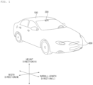
- FIGS. 1 to 7 are diagrams illustrating a vehicle according to the present invention. Hereinafter, a vehicle according to the present invention will be described with reference to FIGS. 1 to 7 .
- a vehicle 100 may include a plurality of wheels, which are rotated by a power source, and a steering input device 510 for controlling a direction of travel of the vehicle 100.
- overall length means the length from the front end to the rear end of the vehicle 100
- the term “overall width” means the width of the vehicle 100
- the term “overall height” means the height from the bottom of the wheel to the roof.
- the term “overall length direction L” may mean the reference direction for the measurement of the overall length of the vehicle 100
- the term “overall width direction W” may mean the reference direction for the measurement of the overall width of the vehicle 100
- the term “overall height direction H” may mean the reference direction for the measurement of the overall height of the vehicle 100.
- the vehicle driving information may include at least one of the following: object information acquired by an object detection apparatus 300, information received by a communication apparatus 400, and a user input received by a user interface apparatus 200 or a driving manipulation apparatus 500.
- the information received by the communication apparatus 400 may be information transmitted and received by a device capable of performing communication.
- the information received by the communication apparatus 400 may include at least one of the following: information transmitted by a nearby vehicle; information transmitted by a mobile terminal; information transmitted by a traffic infrastructure, and information existing in a specific network.
- the traffic infrastructure may include a traffic light, and the traffic light may transmit information about a traffic signal.
- the vehicle driving information may include at least one of the following: navigation information; information on a control state of the vehicle 100; and location information of the vehicle 100.
- the vehicle driving information may include: information on a nearby vehicle, which is transmitted by the nearby vehicle; information on a travel route; and map information.
- the controller 170 may determine: a type, location, and movement of an object in the vicinity of the vehicle 100; whether a line exists in the vicinity of the vehicle 100; whether a stopping area exists in the vicinity of the vehicle 100; a probability of collision between the vehicle 100 and an object; a distribution of pedestrians or bicycles in the vicinity of the vehicle 100; a type of a road in which the vehicle 100 is travelling; a state of a traffic light in the vicinity of the vehicle 100; and movement of the vehicle 100.
- Vehicle driving information may be acquired by at least one of the user interface apparatus 200, the object detection apparatus 300, the communication apparatus 400, the driving manipulation apparats 500, the navigation system 770, a sensing unit 120, an interface unit 130, and a memory 140, The vehicle driving information, and may provide acquired information to the controller 170. Based on the vehicle driving information, the controller 170 may control the vehicle 100 to travel autonomously.
- a control mode of the vehicle 100 may indicate a subject which controls the vehicle 100.
- a control mode of the vehicle 100 may include: an autonomous mode in which the controller 170 or the operation system 700 included in the vehicle 100 controls the vehicle 100; a manual mode in which a driver in the vehicle 100 controls the vehicle 100; and a remote control mode in which a device other than the vehicle 100 controls the vehicle 100.
- the controller 170 or the operation system 700 may control the vehicle 100 based on vehicle driving information. Accordingly, the vehicle 100 may travel without a user command received via the driving manipulation apparatus 500. For example, when the vehicle 100 is in the autonomous vehicle, the vehicle 100 may travel based on information, data, or a signal generated by a driving system 710, a parking-out system 710, and a parking system 750.
- the vehicle 100 When the vehicle 100 is in the manual mode, the vehicle 100 may be controlled based on a user command for at least one of steering, acceleration, and deceleration, which is received via the driving manipulation apparatus 500.
- the driving manipulation apparatus 500 may generate an input signal corresponding to a user command, and provide the input signal to the controller 170.
- the controller 170 may control the vehicle 100 based on the input signal provided from the driving manipulation apparatus 500.
- a device other than the vehicle 100 may control the vehicle 100.
- the vehicle 100 may receive a remote control signal transmitted by another device via the communication apparatus 400.
- the vehicle 100 may be controlled based on a remote control signal.
- the vehicle 100 may enter one of the autonomous mode, the manual mode, and the remote control mode based on a user input received via the user interface apparatus 200.
- a control mode of the vehicle 100 may be switched to one of the autonomous mode, the manual mode, and the remote control mode based on at least one of occupant information, vehicle driving information, and vehicle state information.
- the input unit 210 may be disposed inside the vehicle 100.
- the input unit 210 may be disposed in a region of a steering wheel, a region of an instrument panel, a region of a seat, a region of each pillar, a region of a door, a region of a center console, a region of a head lining, a region of a sun visor, a region of a windshield, or a region of a window.
- the gesture input unit 212 may convert a gesture input of a user into an electrical signal.
- the converted electrical signal may be provided to the interface processor 270 or the controller 170.
- the gesture input unit 212 may sense a three-dimensional (3D) gesture input of a user.
- the gesture input unit 212 may include a plurality of light emitting units for emitting infrared light, or a plurality of image sensors.
- the gesture input unit 212 may sense the 3D gesture input by employing a Time of Flight (TOF) scheme, a structured light scheme, or a disparity scheme.
- TOF Time of Flight
- the touch input unit 213 may convert a user's touch input into an electrical signal.
- the converted electrical signal may be provided to the interface processor 270 or the controller 170.
- the touch input unit 213 may include a touch sensor for sensing a touch input of a user.
- the touch input unit 210 may be formed integral with a display unit 251 to implement a touch screen.
- the touch screen may provide an input interface and an output interface between the vehicle 100 and the user.
- the mechanical input unit 214 may include at least one selected from among a button, a dome switch, a jog wheel, and a jog switch. An electrical signal generated by the mechanical input unit 214 may be provided to the interface processor 270 or the controller 170.
- the mechanical input unit 214 may be located on a steering wheel, a center fascia, a center console, a cockpit module, a door, etc.
- the occupant sensing unit 240 may sense an occupant inside the vehicle 100.
- the occupant sensing unit 240 may include an internal camera 220 and a biometric sensing unit 230.
- the internal camera 220 may acquire images of the inside of the vehicle 100.
- the processor 270 may sense a state of a user based on the images of the inside of the vehicle 100. For example, a sensed state of a user may be about a user's eye gaze, face, behavior, facial expression, and location.
- the interface processor 270 may determine the user's eye gaze, face, behavior, facial expression, and location.
- the interface processor 270 may determine the user's gesture based on an image of the inside of the vehicle 100.
- the determination made by the interface processor 270 based on the image of the inside of the vehicle 100 may be referred to as occupant information.
- the occupant information is information indicating a user's eye gaze direction, behavior, facial expression, and gesture.
- the interface processor 270 may provide the occupant information to the controller 170.
- the biometric sensing unit 230 may acquire biometric information of the user.
- the biometric sensing unit 230 may include a sensor for acquire biometric information of the user, and may utilize the sensor to acquire the user's finger print information, heart rate information, brain wave information, etc.
- the biometric information may be used to authorize the user or to determine the user's state.
- the interface processor 270 may determine a user's state based on a user's biometric information acquired by the biometric sensing unit 230.
- the user's state determined by the interface processor 270 may be referred to as occupant information.
- the occupant information is information indicating whether the user is in faint, dozing off, excited, or in an emergency situation.
- the interface processor 270 may provide the occupant information to the controller 170.
- the display unit 251 may display graphic objects corresponding to various types of information.
- the display unit 251 may include at least one selected from among a Liquid Crystal Display (LCD), a Thin Film Transistor-Liquid Crystal Display (TFT LCD), an Organic Light-Emitting Diode (OLED), a flexible display, a 3D display, and an e-ink display.
- LCD Liquid Crystal Display
- TFT LCD Thin Film Transistor-Liquid Crystal Display
- OLED Organic Light-Emitting Diode
- the display unit 251 may form an inter-layer structure together with the touch input unit 213, or may be integrally formed with the touch input unit 213 to implement a touch screen.
- the display unit 251 may be implemented as a Head Up Display (HUD). When implemented as a HUD, the display unit 251 may include a projector module in order to output information through an image projected on a windshield or a window.
- HUD Head Up Display
- the transparent display may display a predetermined screen with a predetermined transparency.
- the transparent display may include at least one selected from among a transparent Thin Film Electroluminescent (TFEL) display, an Organic Light Emitting Diode (OLED) display, a transparent Liquid Crystal Display (LCD), a transmissive transparent display, and a transparent Light Emitting Diode (LED) display.
- TFEL Thin Film Electroluminescent
- OLED Organic Light Emitting Diode
- LCD transparent Liquid Crystal Display
- LED transparent Light Emitting Diode
- the transparency of the transparent display may be adjustable.
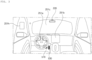
- the user interface apparatus 200 may include a plurality of display units 251a to 251g.
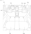
- the display unit 251 may be disposed in a region of a steering wheel, a region 251a, 251b, or 251e of an instrument panel, a region 251d of a seat, a region 251f of each pillar, a region 251g of a door, a region of a center console, a region of a head lining, a region of a sun visor, a region 251c of a windshield, or a region 251h of a window.
- the sound output unit 252 converts an electrical signal from the interface processor 270 or the controller 170 into an audio signal, and outputs the audio signal. To this end, the sound output unit 252 may include one or more speakers.
- the haptic output unit 253 generates a tactile output.
- the tactile output is vibration.
- the haptic output unit 253 vibrates a steering wheel, a safety belt, and seats 110FL, 110FR, 110RL, and 110RR so as to allow a user to recognize the output.
- the interface processor 270 may control the overall operation of each unit of the user interface apparatus 200.
- the user interface apparatus 200 may include a plurality of interface processors 270 or may not include the interface processor 270.
- the user interface apparatus 200 may operate under control of the controller 170 or a processor of a different device inside the vehicle 100.
- the user interface apparatus 200 may be referred to as a multimedia device for vehicle.
- the user interface apparatus 200 may operate under control of the controller 170.
- the objection detection apparatus 300 is configured to detect an object outside the vehicle 100.
- the object may include various objects related to travelling of the vehicle 100.
- an object o may include a lane OB10, a line distinguishing the lane OB10, a nearby vehicle OB11, a pedestrian OB12, a two-wheeled vehicle OB13, a traffic signal OB14 and OB15, a curb for distinguishing a sidewalk a light, a road, a structure, a bump, a geographical feature, an animal, etc.
- the lane OB10 may be a driving lane in which the vehicle 100 is traveling, a lane next to the driving lane, and a lane in which an opposing vehicle is travelling.
- the lane OB10 may include left and right lines that define the lane.
- the nearby vehicle OB11 may be a vehicle that is travelling in the vicinity of the vehicle 100.
- the nearby vehicle OB11 may be a vehicle located within a predetermined distance from the vehicle 100.
- the nearby vehicle OB11 may be a vehicle that is preceding or following the vehicle 100.
- the nearby vehicle OB11 may be a vehicle travelling on a lane next to a lane in which the vehicle 100 is travelling.
- the pedestrian OB12 may be a person in the vicinity of the vehicle 100.
- the pedestrian OB12 may be a person located within a predetermined distance from the vehicle 100.
- the pedestrian OB12 may be a person on a sidewalk or on the roadway.
- the location information unit 420 may acquire GPS information using a GPS module.
- the location information unit 420 may transfer the acquired GPS information to the controller 170 or the communication processor 470.
- the GPS information acquired by the location information unit 420 may be used for autonomous travelling of the vehicle 100. For example, based on GPS information and navigation information acquired using the navigation system 770, the controller 170 may control the vehicle 100 to travel autonomously.
- the V2X communication unit 430 is configured to perform wireless communication between a vehicle and a server (that is, vehicle to infra (V2I) communication), wireless communication between a vehicle and a nearby vehicle (that is, vehicle to vehicle (V2V) communication), or wireless communication between a vehicle and a pedestrian (that is, vehicle to pedestrian(V2P) communication).
- the V2X communication unit 430 may include a radio frequency (RF) circuit that is capable of implementing protocols for the V2I communication, the V2V communication, and V2P communication.
- RF radio frequency
- the light emitting unit may be integrally formed with a lamp provided included in the vehicle 100.
- the ITS communication unit 460 performs communication with a server that provides an intelligent traffic system.
- the ITS communication unit 460 may receive information on various traffic situations from the server of the intelligence traffic system.
- Information on a traffic situation may include a level of traffic congestion, a traffic situation on each road, and an amount of traffics in each area.
- the communication processor 470 may control the overall operation of each unit of the communication apparatus 400.
- Vehicle driving information may include information received using at least one of the short-range communication unit 410, the location information unit 420, the V2X communication unit 430, the optical communication unit 440, and the broadcast transmission and reception unit 450.
- vehicle driving information may include information received from a nearby vehicle, the information which is about a location, a model, route, speed, various sensed values, etc. of a nearby vehicle.
- the controller 170 may acquire information on various objects in the vicinity of the vehicle 100, even through the vehicle 100 does not include an additional sensor.
- the vehicle driving information may indicate the following: a type, location, and movement of an object in the vicinity of the vehicle 100; whether nearby vehicles are travelling at a time when the vehicle 100 is in a stop; whether there is a space available to park in the vicinity of the vehicle 100; a probability that the vehicle 100 collides with an object; a location of any pedestrian or bicycle in the vicinity of the vehicle 100; a type of the roadway on which the vehicle 100 is travelling; the current traffic signal indicated by a traffic light in the vicinity of the vehicle 100; and movement of the vehicle.
- the communication apparatus 400 may operate under control of the controller 170 or a processor of a device inside of the vehicle 100.
- the communication apparatus 400 may implement a vehicle multimedia device, together with the user interface apparatus 200.
- the vehicle multimedia device may be referred to as a telematics device or an Audio Video Navigation (AVN) device.
- APN Audio Video Navigation
- the communication apparatus 400 may operate under control of the controller 170.
- the driving manipulation apparatus 500 is configured to receive a user input for driving the vehicle 100.
- the vehicle 100 may operate based on a signal provided by the driving manipulation apparatus 500.
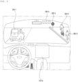
- the driving manipulation apparatus 500 may include a steering input device 510, an acceleration input device 530, and a brake input device 570.
- the steering input device 510 may receive a user command for steering the vehicle 100.
- the user command for steering may be a command corresponding to a specific steering angle.
- a user command for steering may correspond to 45 degrees to right.
- the steering input device 510 may take the form of a wheel to enable a steering input through the rotation thereof.
- the steering input device 510 may be referred to as a steering wheel or a handle.
- the steering input device may be provided as a touchscreen, a touch pad, or a button.
- the acceleration input device 530 may receive a user input for acceleration of the vehicle 100.
- the brake input device 570 may receive a user input for deceleration of the vehicle 100.
- Each of the acceleration input device 530 and the brake input device 570 may take the form of a pedal.
- the acceleration input device or the break input device may be configured as a touch screen, a touch pad, or a button.
- the driving manipulation apparatus 500 may operate under control of the controller 170.
- the vehicle drive apparatus 600 is configured to electrically control the operation of various devices of the vehicle 100.
- the vehicle drive apparatus 600 may include a power train drive unit 610, a chassis drive unit 620, a door/window drive unit 630, a safety apparatus drive unit 640, a lamp drive unit 650, and an air conditioner drive unit 660.
- the vehicle drive apparatus 600 may further include other components in addition to the aforementioned components, or may not include some of the aforementioned components.
- the vehicle drive apparatus 600 may include a processor. Each unit of the vehicle drive apparatus 600 may include its own processor.
- the power train drive unit 610 may control the operation of a power train.
- the power train drive unit 610 may include a power source drive unit 611 and a transmission drive unit 612.
- the power source drive unit 611 may control a power source of the vehicle 100.
- the power source drive unit 611 may perform electronic control of the engine. As such the power source drive unit 611 may control, for example, the output torque of the engine. The power source drive unit 611 may adjust the output toque of the engine under control of the controller 170.
- the power source drive unit 611 may control the motor.
- the power source drive unit 610 may control, for example, the RPM and toque of the motor under control of the controller 170.
- the transmission drive unit 612 may control a transmission.
- the transmission drive unit 612 may adjust the state of the transmission.
- the transmission drive unit 612 may adjust a state of the transmission to a drive (D), reverse (R), neutral (N), or park (P) state.
- the transmission drive unit 612 may adjust a gear-engaged state to the drive position D.
- the chassis drive unit 620 may control the operation of a chassis.
- the chassis drive unit 620 may include a steering drive unit 621, a brake drive unit 622, and a suspension drive unit 623.
- the steering drive unit 621 may perform electronic control of a steering apparatus provided inside the vehicle 100.
- the steering drive unit 621 may change the direction of travel of the vehicle 100.
- the brake drive unit 622 may perform electronic control of a brake apparatus provided inside the vehicle 100. For example, the brake drive unit 622 may reduce the speed of the vehicle 100 by controlling the operation of a brake located at a wheel.
- the brake drive unit 622 may control a plurality of brakes individually.
- the brake drive unit 622 may apply a different degree-braking force to each wheel.
- the suspension drive unit 623 may perform electronic control of a suspension apparatus inside the vehicle 100. For example, when the road surface is uneven, the suspension drive unit 623 may control the suspension apparatus so as to reduce the vibration of the vehicle 100.
- the suspension drive unit 623 may control a plurality of suspensions individually.
- the door/window drive unit 630 may perform electronic control of a door apparatus or a window apparatus inside the vehicle 100.
- the door/window drive unit 630 may include a door drive unit 631 and a window drive unit 632.
- the operation system 700 is a system for controlling the overall driving operation of the vehicle.
- the operation system 700 may operate in the autonomous driving mode.
- the operation system 700 may perform autonomous driving of the vehicle 100 based on location information of the vehicle 100 and navigation information.
- the operation system 700 may include the driving system 710, the parking-out system 740, and the parking system 750.
- the operation system 700 may include a processor. Each unit of the operation system 700 may include its own processor.
- the operation system 700 may be a subordinate concept of the controller 170.
- the operation system 700 may be a concept including at least one selected from among the user interface apparatus 200, the objection detection apparatus 300, the communication apparatus 400, the vehicle drive apparatus 600, and the controller 170.
- the driving system 710 may perform driving of the vehicle 100.
- the driving system 710 may perform autonomous driving of the vehicle 100 by providing a control signal to the vehicle drive apparatus 600 based on location information of the vehicle 100 and navigation information received from the navigation system 770.
- the driving system 710 may perform driving of the vehicle 100 by providing a control signal to the vehicle drive apparatus 600 based on object information received from the objection detection apparatus 300.
- the driving system 710 may perform driving of the vehicle 100 by providing a control signal to the vehicle drive apparatus 600 based on a signal received from an external device through the communication apparatus 400.
- the parking-out system 740 may perform an operation of pulling the vehicle 100 out of a parking space.
- the parking-out system 740 may perform an operation of pulling the vehicle 100 out of a parking space, by providing a control signal to the vehicle drive apparatus 600 based on location information of the vehicle 100 and navigation information received from the navigation system 770.
- the parking-out system 740 may perform an operation of pulling the vehicle 100 out of a parking space, by providing a control signal to the vehicle drive apparatus 600 based on object information received from the objection detection apparatus 300.
- the parking-out system 740 may perform an operation of pulling the vehicle 100 out of a parking space, by providing a control signal to the vehicle drive apparatus 600 based on a signal received from an external device.
- the parking system 750 may perform an operation of parking the vehicle 100 in a parking space.
- the parking system 750 may perform an operation of parking the vehicle 100 in a parking space, by providing a control signal to the vehicle drive apparatus 600 based on location information of the vehicle sd100 and navigation information received from the navigation system 770.
- the parking system 750 may perform an operation of parking the vehicle 100 in a parking space, by providing a control signal to the vehicle drive apparatus 600 based on object information received from the objection detection apparatus 300.
- the parking system 750 may perform an operation of parking the vehicle 100 in a parking space, by providing a control signal to the vehicle drive apparatus 600 based on a signal received from an external device.
- the navigation system 770 may provide navigation information.
- the navigation information may include at least one selected from among map information, information on a set destination, information on a route to the set destination, information on various objects along the route, lane information, and information on a current location of the vehicle.
- the navigation system 770 may include a memory and a processor.
- the memory may store navigation information.
- the processor may control the operation of the navigation system 770.
- the navigation system 770 may update pre-stored information by receiving information from an external device through the communication apparatus 400.
- the navigation system 770 may be classified as an element of the user interface apparatus 200.
- the sensing unit 120 may sense the state of the vehicle.
- the sensing unit 120 may include an attitude sensor (for example, a yaw sensor, a roll sensor, or a pitch sensor), a collision sensor, a wheel sensor, a speed sensor, a gradient sensor, a weight sensor, a heading sensor, a yaw sensor, a gyro sensor, a position module, a vehicle forward/reverse movement sensor, a battery sensor, a fuel sensor, a tire sensor, a steering sensor based on the rotation of the steering wheel, an in-vehicle temperature sensor, an in-vehicle humidity sensor, an ultrasonic sensor, an illumination sensor, an accelerator pedal position sensor, and a brake pedal position sensor.
- an attitude sensor for example, a yaw sensor, a roll sensor, or a pitch sensor
- a collision sensor for example, a yaw sensor, a roll sensor, or a pitch sensor
- a wheel sensor for example, a speed sensor, a gradient sensor
- the sensing unit 120 may acquire sensing signals with regard to, for example, vehicle attitude information, vehicle collision information, vehicle direction information, vehicle location information (GPS information), vehicle angle information, vehicle speed information, vehicle acceleration information, vehicle tilt information, vehicle forward/reverse movement information, battery information, fuel information, tire information, vehicle lamp information, in-vehicle temperature information, in-vehicle humidity information, steering-wheel rotation angle information, ambient illumination information, information about the pressure applied to an accelerator pedal, and information about the pressure applied to a brake pedal.
- Information acquired by the sensing unit 120 may be included in vehicle driving information.
- the sensing unit 120 may further include, for example, an accelerator pedal sensor, a pressure sensor, an engine speed sensor, an Air Flow-rate Sensor (AFS), an Air Temperature Sensor (ATS), a Water Temperature Sensor (WTS), a Throttle Position Sensor (TPS), a Top Dead Center (TDC) sensor, and a Crank Angle Sensor (CAS).
- AFS Air Flow-rate Sensor
- ATS Air Temperature Sensor
- WTS Water Temperature Sensor
- TPS Throttle Position Sensor
- TDC Top Dead Center
- CAS Crank Angle Sensor
- the interface 130 may serve as a passage for various kinds of external devices that are connected to the vehicle 100.
- the interface 130 may have a port that is connectable to a mobile terminal and may be connected to the mobile terminal via the port. In this case, the interface 130 may exchange data with the mobile terminal.
- the interface 130 may serve as a passage for the supply of electrical energy to a mobile terminal connected thereto.
- the interface 130 may provide electrical energy, supplied from the power supply unit 190, to the mobile terminal under control of the controller 170.
- the memory 140 is electrically connected to the controller 170.
- the memory 140 may store basic data for each unit, control data for the operational control of each unit, and input/output data.
- the memory 140 may be any of various hardware storage devices, such as a ROM, a RAM, an EPROM, a flash drive, and a hard drive.
- the memory 140 may store various data for the overall operation of the vehicle 100, such as programs for the processing or control of the controller 170.
- the memory 140 may be integrally formed with the controller 170, or may be provided as an element of the controller 170.
- the power supply unit 190 may supply power required to operate each component under control of the controller 170.
- the power supply unit 190 may receive power from, for example, a battery inside the vehicle 100.
- the controller 170 may control overall operation of each unit of the vehicle 100.
- processors and the controller 170 included in the vehicle 100 may be implemented using at least one selected from among Application Specific Integrated Circuits (ASICs), Digital Signal Processors (DSPs), Digital Signal Processing Devices (DSPDs), Programmable Logic Devices (PLDs), Field Programmable Gate Arrays (FPGAs), processors, controllers, micro-controllers, microprocessors, and electric units for the implementation of other functions.
- ASICs Application Specific Integrated Circuits
- DSPs Digital Signal Processors
- DSPDs Digital Signal Processing Devices
- PLDs Programmable Logic Devices
- FPGAs Field Programmable Gate Arrays
- processors controllers, micro-controllers, microprocessors, and electric units for the implementation of other functions.
- the vehicle 100 may include a lamp 800 for vehicle.
- the lamp 800 may include various lighting devices provided in the vehicle 100.
- the lamp 800 may include a headlamp, a break lamp, a tail lamp, a turn signal lamp, a room lamp, etc.
- the following descriptions, the lamp 800 will be described mainly about a head lamp.
- FIG. 8 is a block diagram of a structure of a lamp for vehicle according to an embodiment of the present invention.
- the lamp 800 may include an input unit 810, a memory 820, an interface unit 840, a lamp module 850, and a controller 860.
- the lamp module 850 may include a light emitting unit 851 and a beam pattern unit 852. In some embodiments, however, some of the elements shown in FIG. 8 may be omitted or a new element may be further included.
- the input unit 810 may receive various user inputs.
- the input unit 810 may be electrically connected to the controller 860 to provide an electrical signal, corresponding a received user input, to the controller. Based on the electrical signal provided from the input unit 810, the controller 860 may generate a control signal corresponding to a user input, and provide the control signal to each unit of the lamp 800.
- the input unit 810 may be disposed inside the vehicle.
- the input unit 810 may be disposed in a region of a steering wheel, a region of an instrument panel, a region of a seat, a region of each pillar, a region of a door, a region of a center console, a region of a head lining, a region of a sun visor, a region of a windshield, or a region of a window.
- the input unit 810 may include at least one of a voice input unit (not shown), a gesture input unit (not shown), a touch input unit (not shown), and a mechanical input unit (not shown).
- the memory 820 is electrically connected to the controller 860.
- the memory 140 may store basic data for each unit, control data for the operational control of each unit, and input/output data.
- the memory 820 may be any of various hardware storage devices, such as a ROM, a RAM, an EPROM, a flash drive, and a hard drive.
- the memory 820 may store various data for the overall operation of the lamp 800, such as programs for the processing or control of the controller
- the memory 820 may be integrally formed with the controller 860 or may be implemented as a subordinate element of the controller 860.
- the power supply unit 830 may supply power required for operations of the controller 860 and each element.
- the interface unit 840 may act as a channel to various kinds of external devices connected to the lamp 800.
- the interface unit 840 may receive various kinds of information from the user interface apparatus 200, the object detection apparatus 300, the communication apparatus 400, and the controller 170.
- the interface unit 840 may receive vehicle driving information and provide the received vehicle driving information to the controller 860.
- the interface unit 840 may provide information, provided by the controller 860 of the lamp 800, to the controller 170 of the vehicle 100.
- the interface unit 84 may have an external port via which connection to an external device is possible, and the interface unit 840 may exchange data with a mobile terminal via the external port.
- the light emitting unit 851 may generate light and output the light.
- the light emitting unit 851 may include a light source unit 651 and a light source drive unit 652.
- the light source unit 651 may be a device that generates light by converting electrical energy into light energy.
- the light source unit 651 may include a light emitting element.
- the light emitting element may include a Light Emitting Diode (LED), or a laser diode.
- the light source unit 651 may include a plurality of light emitting elements.
- the light source unit 651 may include a blue laser diode, a green laser diode, and a red laser diode.
- the light source device may include a plurality of micro LEDs.
- the plurality of micro LEDs may be controlled individually by the light source drive unit 652.
- the light source unit 651 may be driven based on an electrical signal provided from the light source drive unit 652.
- the light source drive unit 652 may provide the light source unit 651 with an electrical signal for driving the light source unit 651.
- the electrical signal provided from the light source drive unit 652 may be generated under the control of the controller 860.
- the light emitting unit 851 may further include a light conversion unit (not shown) and an optical unit (not shown).
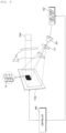
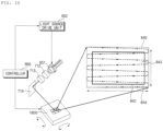
- the DMD module may change postures of multiple fine mirrors included in the DMD in accordance with a control of the controller 860, so that a specific image is displayed on a road surface.
- the DMD module will be described in more detail with reference to FIG. 9 .
- the display module may further include a transparent display panel.
- the controller 860 may control a specific image to be displayed on a transparent display module, and may control a light, output from the light emitting unit 851, to penetrate the transparent display module on which the specific image is displayed. Since the transparent display module has a predetermined transmittivity rate, the light output from the light emitting unit 851 may penetrate the transparent display module. Accordingly, the specific image displayed on the transparent display module may be displayed on a road surface.
- the controller 860 may be electrically connected to each unit of the lamp 800 to control overall operation of each unit.
- the controller 860 may control the lamp module 850 to output a road surface projection image that shows various kinds of information.
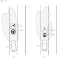
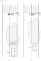
- the controller 860 may control the lamp module 850 to output a road surface projection image corresponding to information which is, for example, about the current time, weather, traffic congestion in an area in which the vehicle 100 is travelling, an expected travel route of the vehicle 100, a set radio frequency, audio volume, set temperature of an air conditioner, a fuel state, a lane keeping state. Accordingly, at least one of a state indicator and an operation indicator may be displayed on a road surface in surroundings of the vehicle 100.
- the controller 860 may control the lamp module 850 to output at least one of a state indicator and an operation indicator.
- the state indicator is a road surface projection image indicating important information needed to be recognized by an occupant
- the operation indicator is a road surface projection image indicating an operation that the occupant needs to perform.
- the state indicator is a road surface projection image indicating important information needed to be recognized by an occupant.
- the state indicator may be a road surface projection image composed of a text or mark that indicates the following: the current speed of the vehicle, a legal speed limit set in an area where the vehicle 100 is travelling, a set driving route, the current time, weather, a schedule set by a user, error information of the vehicle 100, alarming about an object with which the vehicle 100 possibly collides, and notable features on an area in which the vehicle 100 is travelling.
- the operation indicator may be a road surface projection image indicating an operation that the occupant needs to perform.
- the operation indicator may be a road surface projection image composed of a text or mark that requires the occupant to brake, change steering, accelerate, or decelerate.
- the operation indicator may be a road surface projection image which indicates that an occupant in the vehicle 100 is required to turn on a left/right-turn signal, change a battery, operate an air conditioner, change a tire, or fasten a seat belt.
- the controller 860 projects a state indicator. Based on vehicle driving information, the controller 860 may determine whether important information exists. The presence of the important information may indicate occurrence of an event corresponding to the important information. For example, the fact that the vehicle 100 is travelling in an area having a speed limit may be important information, and the presence of the important information may indicate occurrence of an event indicating that the vehicle 100 is travelling in the area having the speed limit.
- the controller 860 may control the lamp module 850 to output a state indicator that corresponds to important information determined to exist.
- the state indicator is displayed on a road surface. An occupant in the vehicle 100 may see the state indicator on the road surface and recognize the important information.
- the important information may be information needed to be recognized by an occupant among driving situation information, vehicle state information, and occupant-related information.
- the important information may be driving situation information needed to be recognized by an occupant.
- the driving situation information needed to be recognized by an occupant may be information about safety or violation of a traffic law by the vehicle 100 among information related to circumstances surrounding the vehicle 100.
- the driving situation information needed to be recognized by an occupant may be information indicating an object which possibly collides with the vehicle 100, a traffic law possibly violated by the vehicle 100, a traffic light located along a travel route, deviation from an expected travel route, lane departure, and entrance into an area to pay attention.
- the controller 860 may determine that important information exists.
- the important information may be at least one of a text and a mark, which indicates at least one of a location, a type, a probability of collision, a risk of collision, and a measure to avoid collision.
- the controller 860 may output at least one of a text and a mark, which indicates at least one of a location, a type, a probability of collision, a risk of collision, and a measure to avoid collision, as a state indicator.
- the controller 860 may determine that important information exists.
- the presence of a traffic law possibly violated by the vehicle 100 may mean that a speed limit is set in an area in which the vehicle 100 is travelling, that a lane in which the vehicle 100 is travelling or into which the vehicle 100 moves is a lane legally not allowed for the vehicle 100, or that an area into which the vehicle 100 is about to enter is a restricted area. Accordingly, if it is determined that a traffic law possibly violated by the vehicle 100 exists in the vicinity of the vehicle 100, the controller 860 may determine that important information exists.
- the important information may be information about, for example, a speed limit, a restricted lane, and a restricted area.
- the controller 860 may output at least one of a text and a mark, which indicates the speed limit, the restricted lane, and the restricted area as a state indicator.
- the controller 860 may determine that important information exists. For example, if it is determined, based on vehicle driving information, that a traffic light located along a travel route is changed, the controller 860 may determine that important information exists. For example, if it is determined to stop in response to the change in the traffic light during travelling of the vehicle 100, the controller 860 may determine that important information exists. In this case, the important information may be information about at least one of a location of the traffic light, a state of the traffic light, an expected signal, and an expected time to change. If the traffic light on the travel route is changed, the controller 860 may determine that important information exists. As a state indicator, the controller 860 may output at least one of a text and a mark, which indicates at least one of the location of the signal light, a signal state, an expected signal, and an expected time to change.
- the controller 860 may determine that important information exists. For example, if the current location of the vehicle 100 is out of a set route or if the vehicle 100 deviates from a set route unless it changes a lane within a predetermined period of time, the controller 860 may determine that there is a probability of route deviation of the vehicle 100. In this case, important information may be information on an expected travel route.
- the controller 860 may output at least one of a text and a mark indicating the expected travel route as a state indicator.
- the controller 860 may determine that important information exists. For example, if an angle of a direction of travel of the vehicle 100 relative to a traffic line is equal to or grater than a predetermined angle, if the center of the vehicle 100 is a predetermined distance or more off the center of a roadway, if the vehicle 100 enters a curve having a curvature equal to or greater than a predetermined value, or if a lane would be seen unclear due to a weather condition, the controller 860 may determine that there is a probability of lane departure of the vehicle 100.
- the important information may be information indicating a form, a direction of travel, and a location of the vehicle 100.
- the controller 860 may output a state indicator indicating at least one of a text and a mark which indicates at least one of the form of a lane, the direction of travel of the vehicle 100, and the location of the vehicle 100.
- the controller 860 may determine that important information exists.
- the area to pay attention may be an accident-prone zone, an icy road, a snowy road, a rainy road, a road filled with many obstacles, and a wildlife crossing zone. If the vehicle 100 is determined to enter into the area to pay attention, the controller 860 may output, as a state indicator, at least one of a text and a mark which indicates the area to pay attention.
- the OBD information may include parking brake state information, high beam ON/OFF state information, washer liquid sate information, motor oil state information, power source overheat information, battery state information, fuel state information, tire pressure state information, brake oil state information, side mirror state information, information relating to an opened state of a trunk, information relating to a safety belt fastening state information, and door-opened-state information.
- the controller 860 may determine that important information exists.
- the important information may be information about a device in which an error occurs.
- the controller 860 may output at least one of a text and a mark which indicates the device where an error occurred, as a state indicator.
- the controller 860 may determine that important information exists.
- the important information may be information about the current speed of the vehicle 100 and the speed limit.
- the controller 860 may output at least one of a text and a mark, which indicates the current speed of the vehicle 100 and the speed limit.
- the controller 860 may determine that important information exists. For example, if the On state of a high beam is detected when an opposing vehicle is coming close, if the Off state of the high beam detected when illumination is equal to or smaller than a preset value, if a lack of washer liquid is detected, if a lack of motor oil is detected, if overheat of a power source is detected, if running out of a battery is detected, if an error in tire pressure is detected, if a lack of break oil is detected, if folding of a side mirror is detected during travelling of the vehicle 100, if opening of a trunk is detected, if unfastening of a seat belt is detected, or if opening of a door is detected, the controller 860 may determine detected information is important information. The controller 860 may output at least one of a text and a mark, which indicates the detected information, as a state indicator.
- the important information may be occupant-related information needed to be recognized by an occupant.
- the occupant-related information may include at least one of the followi9ng: information about a mobile terminal of the occupant, Point of Interest (POI) information of the occupant, schedule information of the occupant, and occupant state information provided by the occupant sensing unit.
- the vehicle driving information may include the occupant-related information. Based on the vehicle driving information, the controller 860 may determine whether there is occupant-related information needed to be recognized by an occupant.
- the controller 860 may determine that important information exists.
- important information may be information about the incoming call or text message.
- the controller 860 may output at least one of a text and a mark which indicates caller information and content of the incoming call or text message, as a state indicator.
- the controller 860 may determine that important information exists.
- the important information may be information about the POI of the occupant, which is located within the preset distance from the vehicle 100.
- the controller 860 may output at least one of a text and a mark which indicates the information about the POI of the occupant located within the preset distance from the vehicle 100.
- the controller 860 may determine that important information exists.
- the important information may be information about the schedule of the occupant corresponding to the current time.
- the controller 860 may output at least one of a text and a mark, which indicates the schedule of the occupant corresponding to the current time.
- the controller 860 may project an operation indicator.
- the operation indicator may be a road surface projection image which indicates an operation that the occupant needs to perform.
- the operation indicator may include a first operation indicator indicating an operation related to the driving manipulation apparatus 500 (see FIG. 7 ), and a second operation indicator indicating an operation unrelated to the driving manipulation apparatus 500 (see FIG. 7 ).
- the operation related to the driving manipulation apparatus 500 may include changing a steering direction of the vehicle 100 by manipulating the steering input device 510 (see FIG. 7 ), changing a speed of the vehicle 100 by manipulating the acceleration input device 520 (see FIG. 7 ), or braking the vehicle 100 by manipulating the brake input device 530 (see FIG. 7 ).
- the operation unrelated to the driving manipulation apparatus 500 may be an operation of manipulating a device other than the driving manipulation apparatus 500 (see FIG. 7 ) among devices included in the vehicle 100.
- an operation that an occupant needs to perform may be fastening a seat belt, or operating a device such as a wiper and an air conditioner.
- An operation that an occupant needs to perform may be a specific operation that the occupant needs to perform in order to prevent the dangerous situation.
- the operation that the occupant needs to perform may be an operation required to prevent the vehicle 100 from colliding with an object, violating a traffic law/signal, deviating from a lane, or deviating from a preset travel route.
- the controller 860 may determine the specific operation required to prevent the dangerous situation.
- the dangerous situation may be an event related to safety of the vehicle 100, collision with an object, violation of a traffic signal, violation of a traffic law, lane departure, and route deviation.
- the dangerous situation may be an event in which the vehicle 100 collides with an object.
- the object may be a nearby vehicle, a pedestrian, a structure, an animal, and any other obstacle.
- the controller 860 may determine whether the vehicle 100 is expected to collide with an object if the vehicle 100 is maintained in the current driving state.
- the controller 860 may determine manipulation of the driving manipulation apparatus 500 (see FIG. 7 ), which is required for an occupant to perform in order to avoid the object.
- the controller 860 may output, as an operation indicator, a text or mark which indicates manipulation of the driving manipulation apparatus 500 (see FIG. 7 ) required for the occupant to perform.
- the dangerous situation may be an event in which the vehicle 100 violates a traffic law or signal.
- the controller 860 may display an operation, which is required for an occupant to perform in order to avoid violation of the traffic law, as a road surface projection image.
- the dangerous situation may be an event in which the vehicle 100 deviates from a lane or an expected route.
- the controller 860 may display an operation, which is required for an occupant to perform in order to avoid the lane departure or the route deviation, as a road surface projection image.
- the operation indicator may include a target operation indicator, which indicates a target operation required for the occupant to perform, and an ongoing operation indicator, which indicates an operation being performed by the occupant.
- the controller 860 may display the target operation indicator and the ongoing operation indicator in the form of dynamic images that move in accordance with a manipulation state of the driving manipulation apparatus 500 (see FIG. 7 ).
- the target operation indicator and the ongoing operation indicator are displayed in the form of dynamic images that moves in accordance with a manipulation state of the driving manipulation apparatus 500 (see FIG. 7 ).
- the controller 860 may determine at least one of a location, form, or projection time of a state indicator or operation indicator.
- controller 860 determines a form or projection time of the state indicator based on vehicle driving information.
- the controller 860 may determine at least one of a form and a projection time of the state indicator in response to a caution level of important information.
- the controller 860 may determine the caution level of important information based on vehicle driving information.
- the caution level of important information is an indicator showing that an occupant needs to recognize the important information.
- caution levels may range from Level 1 to Level 5.
- An increased caution level of important information may mean an increased need for recognition of important information by an occupant.
- a caution level of important information about collision between the vehicle 100 and an object may increase in proportion to a probability of collision.
- a caution level of important information about violation of a traffic law by the vehicle 100 may increase in proportion to a probability of violation of a traffic law.
- the controller 860 may determine a probability of coalition, a probability of violation of a traffic law, a probability of lane departure, and a degree of danger in the current driving area. Based on the determination as to the probability of coalition, the probability of violation of a traffic law, the probability of lane departure, and the degree of danger in the current driving area, the controller 860 may determine a caution level of important information. For example, the controller 860 may determine that a caution level increases if the probability of coalition, the probability of violation of a traffic law, the probability of lane departure, or the degree of danger in the current driving area is high.
- the controller 860 may determine the form of a state indicator corresponding to the important information.
- the form of the state indicator may be a concept including at least one of a location, a shape, a size, content, or brightness of the state indicator to be projected on a road surface.
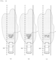
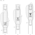
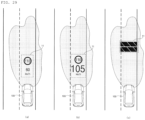
- the controller 860 may determine the form of a state indicator, so that a caution level of important information and a size of a state indicator becomes proportional to each other.
- the size of the state indicator may increase in proportion to the caution level.
- the controller 860 may change a color of a state indicator. For example, if a caution level is smaller than a set value, the controller 860 may determine yellow to be color of a state indicator. If a caution level is equal to or higher than a preset value, the controller 860 may determine red to be color of a state indicator.
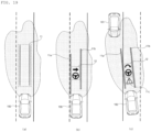
- the controller 860 may determine the form of a state indicator such that the higher the caution level of important information, the simpler the form or content of the state indicator becomes.
- the fact that the content of a state indicator becomes simple may mean any one of the following: a state indicator consisting of a text and a mark has changed to consist of either the text or the mark; a text or mark of a state indicator becomes simple; a state indicator consisting of a mark has changed to consist of a text; or a state indicator consisting of a text has changed to consist of a mark.
- the controller 860 may advance the projection time of a state indicator if a caution level of important information increases.
- the projection time is the time at which the state indicator or the operation indicator starts to be projected. Accordingly, a state indicator showing important information with a relatively high caution level may be displayed earlier than a state indicator showing important information with a relatively low caution level.
- controller 860 determines a form or projection time of an operation indicator based on vehicle driving information.
- the controller 860 may determine at least one of a form and a projection time of an operation indicator.
- the controller 860 may determine a caution level of the dangerous situation based on vehicle driving information.
- a caution level of the dangerous situation is an indicator showing a degree of danger in a dangerous situation.
- caution levels may range from Level 1 to Level 5.
- An increased caution level of a dangerous situation may mean an increased degree of danger in the dangerous situation.
- a caution level of a dangerous situation related to collision of the object 100 with an object may increase in proportion to a probability of the collision.
- a caution level of a dangerous situation related to violation of a traffic law by the vehicle 100 may increase in proportion to a probability of violation of a traffic law by the vehicle 100.
- the controller 860 may determine a probability of collision, a probability of violation of a traffic law, a probability of lane departure, and a degree of danger in an area in which the vehicle 100 is travelling, wherein the probability of collision, the probability of violation of a traffic law, the probability of lane departure, and the degree of danger in an area in which the vehicle 100 is travelling correspond to a dangerous situation. Based on the determination as to the probability of collision, the probability of violation of a traffic law, the probability of lane departure, and the degree of danger in the current driving area, the controller 860 may determine a caution level of the dangerous situation. For example, the controller 860 may determine that the higher the probability of collision, the probability of violation of a traffic law, the probability of lane departure, or the degree of danger in the current driving area, the higher the caution level becomes.
- the controller 860 may determine the form of an operation indicator corresponding to the dangerous situation.
- the form of an operation indicator is a concept including at least one of a location, a shape, a size, content, or brightness of the operation indicator to be projected on a road surface.
- the controller 860 may determine the form of an operation indicator, so that the size of the operation indicator becomes proportional to a caution level of a dangerous situation. In this case, the higher the caution level, the greater the size the operation indicator.
- the controller 860 may change color of an operation indicator. For example, if a caution level of a dangerous situation is smaller than a set value, the controller 860 may determine yellow to be color of an operation indicator. For example, if a caution level of a dangerous situation is equal to or higher than a set value, the controller 860 may determine red to be color of an operation indicator.
- the controller 860 may determine the form of an operation indicator such that the higher the caution level of a dangerous situation, the simpler the form or content of the operation indicator becomes.
- the fact that the content of an operation indicator becomes simple may mean any one of the following: an operation indicator consisting of a text and a mark has changed to consist of either the text or the mark; a text or mark of an operation indicator becomes simple; that an operation indicator consisting of a mark has changed to consist of a text; or an operation indicator consisting of a text has changed to consist of a mark.
- the controller 860 may advance the projection time of an operation indicator if a caution level of a dangerous situation increases. Accordingly, an operation indicator showing a dangerous situation with a relatively high caution level may be displayed earlier than an operation indicator showing a dangerous situation with a relatively low caution level.
- the controller 860 may determine a projection location of an operation indicator to be a region on a road surface, at which an occupant is staring.
- the controller 860 may determine area region outside the vehicle 100, at which an occupant is staring.
- the controller 860 may determine a location of the operation indicator, so that the operation indicator is displayed in a region on a road surface, which is stared at by an occupant. As a result, a driver of the vehicle 100 is able to quickly recognize the operation indicator and thus rapidly perform an operation for avert a dangerous situation.
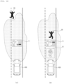
- the controller 860 may determine a projection location of a state indicator to be a region on a road surface, which corresponds to an object related to important information.
- the controller 860 may determine a region on a road surface, which corresponds to the object related to the important information. For example, if important information is information about an object which possibly collides with the vehicle 100, a region on a road surface corresponding to an object related to the important information may be a region within a predetermined distance from the object which possibly collide with the vehicle 100. For example, if important information is information about a driving lane from which the vehicle 100 possibly deviates, a region on a road surface corresponding to an object related to the important information may be a region within a predetermined distance from the driving lane in which the vehicle 100 is travelling.
- the controller 860 may determine a location of the state indicator, so that the state indicator is displayed in a region on a road surface, which corresponds to an object related to important information.
- the controller 860 may determine a projection location of a state indicator or an operation indicator, so that an interval between the vehicle 100 and the state indicator or operation indicator becomes proportional to a speed of the vehicle 100.
- the controller 860 may control the lamp module 850, so that the greater the speed of the vehicle 100, the further the state indicator or the operation indicator displayed from the vehicle 100. If a speed of the vehicle 100 increases, a driver looks further ahead. Accordingly, the lamp 800 according to the present invention may determine a location of a state indicator or an operation indicator in proportion of a speed of the vehicle 100, so that a driver can easily recognize the state indicator or the operation indicator.
- the controller 860 may output at least one of a state indicator and an operation indicator, and then change the state indicator or the operation indicator based on vehicle driving image.
- the controller 860 may change the form of the projected state indicator.
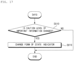
- the controller 860 may output a state indicator, and then determine a caution level of important information corresponding to the output state indicator. Based on the determined caution level, the controller 860 may change the form of the state indicator corresponding to the important information.
- the form of the state indicator is a concept including at least one of a location, a shape, a color, a size, content, and brightness of the state indicator.
- the controller 860 may change the size of a state indicator.
- the controller 860 may change the form of the state indicator, so that the size of the state indicator becomes proportional to the caution level of the important information. In this case, the higher the caution level, the greater the size of the state indicator displayed on a road surface.
- the controller 860 may change a color of a state indicator. For example, the controller 860 may control the lamp module 850 such that the state indicator changes from yellow to red when a caution level of important information increases.
- the controller 860 may change the form of a state indicator, so that the content or form of the state indicator becomes simple.
- the fact that the content of a state indicator becomes simple means any one of the following: a state indicator consisting of a text and a mark has changed to consist of either the text or the mark; a text or mark of a state indicator becomes simple; a state indicator consisting of a mark has changed to consist of a text; or a state indicator consisting of a text has changed to consist of a mark.
- the controller 860 may stop projecting of the operation indicator. Based on vehicle driving information, the controller 860 may determine whether a dangerous situation corresponding to the projected operation indicator is addressed. If it is determined that the dangerous situation corresponding to the operation indicator is addressed, the controller 860 may control the lamp module 850 to stop outputting the operation indicator.
- the controller 860 may stop projecting of the operation indicator. Based on vehicle driving information, the controller 860 may determine whether a driver performs an operation corresponding to the projected operation indicator. For example, in the case where an operation indicator is projected to indicate turning a steering wheel to the right at a specific angle, if it is determined, based on vehicle driving information, that the steering wheel of the vehicle 100 is turned to the specific angle in the right direction, the controller 860 may determine that an operation corresponding to the operation indicator is performed. If the operation corresponding to the operation indicator is performed, a dangerous situation corresponding to the projected operation indicator may be addressed. Thus, the controller 860 may control the lamp module 850 to make the projected operation indicator disappear.
- the controller 860 may project a state indicator. Then, if a dangerous situation is expected to happen, the controller 860 may stop projecting the state indicator and instead project an operation indicator. If it is determined that a state indicator is being projected and a dangerous situation exists, the controller 860 may control the lamp module 850 to make the state indicator disappear and to output an operation indicator corresponding to the determined dangerous. In this case, only the operation indicator is displayed on a road surface, and therefore, a driver may quickly and accurately recognize the operation indicator.
- the controller 860 may determine a waring level of important information or a dangerous situation based on vehicle driving situation. Then, the controller 860 may control the lamp module 850, so that the higher the determined caution level, the faster the state/operation indicator flashes. As a result, at a higher caution level, a driver may quickly recognize the state/operation indicator.
- the controller 860 may be implemented using at least one selected from among Application Specific Integrated Circuits (ASICs), Digital Signal Processors (DSPs), Digital Signal Processing Devices (DSPDs), Programmable Logic Devices (PLDs), Field Programmable Gate Arrays (FPGAs), processors, controllers, micro-controllers, microprocessors, and electric units for the implementation of other functions.
- ASICs Application Specific Integrated Circuits
- DSPs Digital Signal Processors
- DSPDs Digital Signal Processing Devices
- PLDs Programmable Logic Devices
- FPGAs Field Programmable Gate Arrays
- processors controllers, micro-controllers, microprocessors, and electric units for the implementation of other functions.
- FIG. 9 is a diagram for explanation of displaying a road surface projection image using a DMD module according to an embodiment of the present invention.
- the light emitting unit 851 may include a light source unit 651, a light source drive unit 652, a light conversion unit 712, and an optical unit 711.
- the beam pattern unit 852 may include a DMD module 1700.
- a light emitting element included in the light source unit 651 may convert electrical energy into light.
- a light emitting element in the light source unit 651 may include a Light Emitting Diode (LED) or a laser diode.
- LED Light Emitting Diode
- the laser diode may realize brightness much greater than an LED. The following description is provided in the assumption that a laser diode is used as the light source unit 651.
- the light source drive unit 652 may provide the light source unit 651 with an electrical signal for driving the light source unit 651.
- the electrical signal provided by the light source drive unit 652 may be generated under the control of the controller 860.
- the light conversion unit 712 may convert a laser beam, emitted from the light source unit 651, into a specific color.
- a laser beam, emitted from the light source unit 651 may be converted into lights of multiple wavelengths when passing through the light conversion unit 712. Lights of multiple wavelengths are combined into a visible light of a specific color (for example, white).
- the light conversion unit 712 may include at least one type of phosphor.
- the light conversion unit 712 may include a phosphorous.
- the optical unit 711 may include a first lens 712 and a second lens 715.
- the first lens 713 may cause visible light, which is incident through the light conversion unit 712, to be refracted and provide the refracted light toward the DMD module 1700.
- the first lens 713 may cause a visible light, which is emitted from the light conversion unit 712, to be refracted, so that the visible light is transferred to the DMD module 1700.
- the first lens 713 may be a collimator lens.
- the incident visible light may be collimated by the first lens 713.
- the DMD module 1700 may change a pattern of incident visible light.
- the DMD module 1700 may determine a road surface projection image by changing the pattern of the visible light.
- the DMD module 1700 may change a displayed road surface projection image by changing the pattern of the visible light.
- the DMD module 1700 may include a plurality of micro-mirrors M.
- the DMD module 1700 may include tens of thousands of micro-mirrors M.
- the DMD module 1700 may include: a mirror layer including a plurality of micro-mirrors; a drive layer including a plurality of yokes formed to respectively correspond to the plurality of micro-mirrors and plurality of hinges; a metal layer at which the plurality of yokes arrives and which supports the plurality of hinges; and a semiconductor memory 820 (e.g., a CMOS SRAM).
- a mirror layer including a plurality of micro-mirrors
- a drive layer including a plurality of yokes formed to respectively correspond to the plurality of micro-mirrors and plurality of hinges
- a metal layer at which the plurality of yokes arrives and which supports the plurality of hinges
- a semiconductor memory 820 e.g., a CMOS SRAM
- the plurality or yokes and hinges included in the drive layer may receive a signal from the semiconductor memory 820 to adjust a posture of each of the micro-mirrors.
- the plurality of yokes and hinges may make the plurality of micro-mirrors tilted in accordance with a signal provided from the semiconductor memory 820.
- the semiconductor memory 820 may provide a signal for adjusting the posture of the plurality of micro-mirrors.
- the controller 860 may adjust a projection angle and/or reflectance of a visible light on a pixel unit basis.
- each micro-mirror M may change a tilt angle more than thousands of times per second due to a magnetic field. Due to the change of the tilt angle, a tilt angle of at least part of visible light emitted from the first lens 713 toward the DMD module 1700 may be changed. Accordingly, at least part of the visible light emitted from the first lens 713 may be blocked from being projected on the front of the vehicle 100.
- the DMD module 1700 Due to the DMD module 1700, at least part of visible light emitted from the first lens 713 may pass through the second lens 715 and be then projected on the front of the vehicle 100. In some embodiments, the second lens 715 may be omitted.
- the controller 860 may control the posture of some micro-mirrors M included in the DMD module 1700 so as to realize visible lights in various patterns. By controlling the posture of the micro-mirrors M, the controller 860 may display a road surface projection image corresponding to the first information in the outside of the vehicle 100. By controlling the posture of the micro-mirrors M, the controller 860 may change the road surface projection image displayed to correspond to second information.
- the DMD module 1700 in FIG. 9 may output a visible light for displaying a road surface projection image, and a visible light for securing visibility.
- the controller 860 may output, at an interval, the visible light for displaying a road surface projection image and the visible light for securing visibility.
- the controller 860 may output both the two types of visible light.
- the light emitting unit 851 may further include one or more reflectors which is disposed on an optical path along which light, generated by the light source unit 651, is output to the outside.
- FIG. 10 is a diagram for explanation of displaying a road surface projection image using an MEMS scanner module according to an embodiment of the present invention.
- the light emitting unit 851 may include a light source unit 651, a light source drive unit 652, a light conversion unit 712, an optical unit 713, and a reflector 716.
- the beam pattern unit 852 may include an MEMS scanner module 1800.
- a light emitting element included in the light source unit 651 may convert electrical energy into light.
- a light emitting element of the light source unit 651 may include a Light Emitting Diode (LED) or a laser diode.
- LED Light Emitting Diode
- a laser diode When a laser diode is used as a light source, it may realize brightness greater than LED. The following description is provided in the assumption that a laser diode is used as the light source unit 651.
- the light source drive unit 652 may provide the light source unit 651 with an electrical signal for driving the light source unit 651.
- the electrical signal provided by the light source drive unit 652 may be generated under the control of the controller 860.
- the light conversion unit 712 may convert a color of a laser beam emitted toward the light source unit 651 into a specific color.
- a laser beam emitted from the light source unit 651 may be converted into lights of multiple wavelengths when passing through the light conversion unit 712.
- the lights of multiple wavelengths may be combined into a visible light of a specific color (e.g., white).
- the light conversion unit 712 may include at least one type of phosphor.
- the light conversion unit 712 may include a phosphorus.
- the optical unit 713 may include a first lens 713.
- the first lens 713 may cause visible light, which is incident through the light conversion unit 712, to be refracted and provide the refracted light to the MEMS scanner module 1800.
- the first lens 713 may cause visible light, emitted from the light conversion unit 712, to be refracted, so that the visible light is transferred to the MEMS scanner module 1800.
- the first lens 713 may be a collimator lens.
- the incident visible light may be collimated by the first lens 713.
- the reflector 716 may change an optical path.
- the reflector 716 may reflect light passing through the first lens 713, so that the light is transferred to the MEMS scanner module 1800.
- the reflector 716 may be omitted.
- the MEMS scanner module 1800 may include: a scanner mirror, a structure which supports a scanner mirror; and a drive unit for driving the scanner mirror.
- the drive unit may include a magnet.
- the drive unit may rotate the scanner mirror based on an electromagnetic wave that is generated by an applied current.
- the drive unit may drive the scanner mirror under the control of the controller 860.
- the scanner mirror may be rotated upon operation of the drive unit. As the scanner mirror is rotated, an optical path for a visible light incident on the scanner mirror may be changed continuously.
- the MEMS scanner module 1800 may generate a scanning path based on rotation of the scanner mirror.
- the scanning path may be a path along which a visible light reflected by the scanner mirror is output.
- the MEMS scanner module 1800 may receive a visible light, and perform a first-direction scanning and a second-direction scanning sequentially and repeatedly.
- the MEMS scanner module 1800 may scan a scannable area in an external region 840 from left to right and then from right to left in a diagonal or horizontal direction. In addition, the MEMS scanner module 1800 may repeatedly perform such a scanning operation on the entire area of the external region 840. As a result, a projection image corresponding to a visible light may be displayed in the outside.
- the controller 860 By controlling rotation of the scanner mirror, the controller 860 is able to control a scanning path and therefore realize a visible light of various patterns. By controlling rotation of the scanner mirror, the controller 860 may display a road surface projection image corresponding to first information in an area outside the vehicle 100. By controlling rotation of the scanner mirror, the controller 860 may change a displayed road surface projection image to correspond to second information.
- the MEMS scanner module 1800 in FIG. 10 may output both visible light for displaying a road-surface-projected light and visible light for securing visibility.
- the controller 860 may output, at an interval, the two types of visible light.
- the MEMS scanner module 1800 may output both the two types of visible light.
- FIG. 11 is a diagram for explanation of a lamp for vehicle according to an embodiment of the present invention in the case where a plurality of light sources is included in a light emitting unit.
- the light emitting unit 851 may include a light source unit 651, a light source drive unit 652, an optical unit 713, a light combining unit 920, and a reflector 716.
- the light source unit 651 may include a plurality of light emitting elements 651R, 651G, and 651B.
- the light source unit 651 may include a red laser diode 651R, a green laser diode 651G, and a blue laser diode 651B.
- the light source drive unit 652 may provide the light source unit 651 with an electrical signal for driving the light source unit 651.
- the electrical signal provided by the light source drive unit 652 may be generated under the control of the controller 860.
- a red light, a green light, and a blue light output from the light source units 651R, 651G, and 651B may be collimated via each collimator lens in the optical unit 711.
- the light combining unit 920 may combine lights output from the light source unit 651R, 651G, and 651B, and output a combined light in one direction.
- the light combining unit 920 may include three 2D MEMS mirrors 920a, 920b, and 920c. a first light combining unit 920a, a second light combining unit 920b, and a third light combining unit 920c may respectively output a red light from a red light source unit 651R, a green light from a green light source unit 651G, and a blue light from a blue light source unit 651B in a direction toward the beam pattern unit 852.
- the reflector 716 reflects the red light, the green light, and the blue light, which pass through the light combining unit 920, in the direction toward the beam pattern unit 852.
- the reflector 716 may reflect lights of various wavelengths, and, to this end, the reflector TM may be implemented as a Total Mirror (TM).
- the beam pattern unit 852 may selectively include a Digital Micro-mirror Device (DMD) module 1700, and a Micro Electro Mechanical System (MEMS) scanner module 1800.
- DMD Digital Micro-mirror Device
- MEMS Micro Electro Mechanical System
- the controller 1700 may display a road surface projection image corresponding to first information, and change the displayed road surface projection image to correspond to second image.
- the controller 860- may display a road surface projection image corresponding to first information, and change the displayed road surface projection image to correspond to second information.
- FIG. 12 is a diagram for explanation of a light source unit according to an embodiment of the present invention.
- the light source unit 651 may include a plurality of light emitting elements arranged in a predetermined form.
- the light source unit 651 may include a plurality of micro LEDs 1010 as light emitting elements.
- Each of the micro LEDs 1010 may be turned on/off individually under the control of the controller 860. Color and brightness of light from each micro LED 1010 may be adjusted individually under the control of the controller 860.
- the controller 860 may output both a visible light for displaying a road surface projection image and a visible light for securing visibility.
- the controller 860 may control the micro LEDs 1010 on a group unit basis. For example, the controller 860 may control a first group of micro LEDs to output a visible light for displaying an image, and control a second group of micro LEDs to output a visible light for securing visibility.
- FIG. 13 is a flowchart for explanation of how the lamp according to the present invention outputs a state indicator or an operation indicator.
- the controller 860 of the lamp 800 may acquire vehicle driving information during driving of the vehicle 100 in S100.
- the vehicle driving information may be information that is provided, during driving of the vehicle 100, from at least one of the following: the user interface apparatus 200, the object detection apparatus 300, the communication apparatus 400, the driving manipulation apparatus 500, the vehicle drive apparatus 600, the operation system 700, the navigation system 700, the sensing unit 120, the interface unit 130, and the memory 140.
- the controller 170 of the vehicle 100 acquire vehicle driving information and transfers the vehicle driving information to the controller 860 of the lamp 800.
- the controller 860 may determine whether to display each of a state indicator and an operation indicator individually.
- the controller 860 may determine whether there is important information needed to be recognized by an occupant in the vehicle 100 in S210.
- the important information is information needed to be recognized by an occupant among driving situation information, vehicle state information, and occupant-related information.
- the controller 860 may determine a form and projection time of a state indicator based on a caution level of the important information in S310.
- the controller 860 may determine a caution level of determined important information.
- a caution level may indicate a degree of necessity of recognizing important information by an occupant.
- the higher degree of necessity of recognizing important information by an occupant the higher caution level of the important information.
- the greater the probability of collision the higher the caution level of important information related to collision between the vehicle 100 and an object.
- the greater the probability of violation of a traffic law by the vehicle 100 the higher the caution level related to important information related to violation of the traffic law by the vehicle 100.
- the form of a state indicator may include a size, a location, a color, a shape, and content of the state indicator.
- the controller 860 may determine the form of a state indicator, so that the size of the state indicator becomes proportional to a caution level of important information. For example, in the case where caution levels range from level 1 to level 5, the size of a state indicator may be set in advance from level 1 to level 5. In this case, the higher the caution level of important information, the greater the size of the state indicator.
- the controller 860 may determine the form of a state indicator so that the higher the caution level of important information, the simpler the content the state indicator becomes.
- the fact that the content of a state indicator becomes simple may mean any one of the following: a state indicator consisting of a text and a mark has changed to consist of either the text or the mark; a text or mark of a state indicator becomes simple; a state indicator consisting of a mark has changed to consist of a text; or a state indicator consisting of a text has changed to consist of a mark.
- the controller 860 may advance the projection time of a state indicator if a caution level of important information increases. Accordingly, if a state indicator indicates important information with a relatively higher waring level, the state indicator may be displayed earlier than a state indicator indicating important information with a relatively lower level.
- the controller 860 may project the state indicator based on the determined state indicator and projection time in S410.
- the controller 860 may control the lamp module 850, so that the state indicator is output in the determined form at the projection time.
- the controller 860 may determine whether a dangerous situation occurs if an occupant does not perform a specific operation in S220.
- the specific operation may be an operation that the occupant manipulates at least one device provided in a vehicle.
- the specific operation may be an operation that an occupant manipulates at least one of a steering wheel, an accelerator pedal, and a brake pedal.
- the dangerous situation may include situations where the vehicle 100 collides with an object, where the vehicle 100 violates a traffic law or a traffic signal, where the vehicle 100 violates driving of a nearby vehicle, where the vehicle 100 enters a restricted area, or where the vehicle 100 deviates from a lane or an expected route.
- the dangerous situation may be a situation where a headlight of the vehicle 100 is turned on when an opposing vehicle is approaching.
- the dangerous situation may be a situation where the vehicle 100 violates a speed limit.
- the controller 860 may determine whether a dangerous situation occurs. In addition, to prevent a dangerous situation, the controller 860 may determine an operation needed to be performed by an occupant. For example, in a dangerous situation where the vehicle 100 is travelling at or above a speed limit, the controller 860 may determine that an operation needed to be performed by an occupant is decelerating the vehicle 100 using a brake pedal. In this case, an operation indicator may consist of a text or mark indicating manipulation of a brake pedal.
- the controller 860 may determine the form and projection time of the operation indicator based on a caution level of the dangerous situation in S320.
- the controller 860 may determine a caution level of the determined dangerous situation.
- a caution level may indicate a degree of danger in a dangerous situation. Accordingly, the higher the degree of danger in a situation, the higher the caution level of the dangerous situation. For example, the greater the probability of collision between the vehicle 100 and an object, the higher the caution level of a dangerous situation related to the collision. In addition, the greater the probability of violation of a traffic law by the vehicle 100, the higher the caution level of a dangerous situation related to the violation of the traffic law by the vehicle 100.
- the form of an operation indicator may be a concept including a size, a location, a color, a shape, and content of the operation indicator.
- the controller 860 may determine the form of an operation indicator, so that the size of the operation indicator becomes proportional to a caution level of a dangerous situation. For example, if caution levels of a dangerous situation range from level 1 to level 5, the size of an operation indicator may be set in advance from level 1 to level 5 . In this case, the size of the operation indicator may increase if a caution level of the dangerous situation increases.
- the controller 860 may determine the form of an operation indicator, so that the higher the caution level of a dangerous situation, the simpler the content the operation indicator becomes.
- the fact that the content of an operation indicator becomes simple may mean any one of the following: an operation indicator consisting of a text and a mark has changed to consist of either the text or the mark; a text or mark of an operation indicator becomes simple; an operation indicator consisting of a mark has changed to consist of a text; or an operation indicator consisting of a text has changed to consist of a mark.
- the controller 860 may advance the projection time of an operation indicator if a caution level of a dangerous situation increases. Accordingly, an operation indicator corresponding to a dangerous situation with a relatively higher caution level may be displayed earlier than an operation indicator corresponding to a dangerous situation with a relatively lower caution level.
- the controller 860 may project the operation indicator based on a determined form and a determined projection time in S410.
- the controller 860 may control the lamp module 850, so that the operation indicator is displayed in the determined form at the determined projection time.
- FIGS. 14 to 16 are diagrams for explanation of an example in which a lamp for vehicle according to the present invention outputs at least one of a state indicator and an operation indicator.
- the controller 860 may determine, based on vehicle driving information, whether there is a speed limit for an area in which the vehicle 100 is travelling.
- vehicle driving information may include: navigation information indicating a speed limit for each area; and object information indicating a detected speed limit plate. Based on the navigation information, the controller 860 may determine a speed limit for an area where the vehicle 100 is travelling. Based on object information, the controller 860 may sense a speed limit shown in a traffic plate.
- Information on a speed limit for an area where the vehicle 100 is travelling, and information on the current speed of the vehicle 100 are related to violation of a traffic law by the vehicle 100, and thus, those information are important information needed to be recognized by an occupant. If it is determined that a speed limit is set in an area where the vehicle 100 is travelling, the controller 860 may determine that important information exists.
- the controller 860 may control the lamp module 850 to output a state indicator 11 indicating a speed limit and the current speed of the vehicle 100. For example, if a speed limit is 110km/h, the controller 860 may project, as the state indicator 11, a mark indicating the speed limit of 110km/h and a text indicating the current speed of the vehicle 100. As a result, the mark indicating the speed limit of 110km/h and the text indicating the current speed of the vehicle 100 may be displayed within a light pattern formed on the front of the vehicle 100.
- the controller 860 may determine, based on vehicle driving information, whether the vehicle 100 exceeds a speed limit.
- vehicle driving information may include speed information of the vehicle 100 and information on a speed limit for an area where the vehicle 100 is travelling.
- the controller 860 may determine whether a dangerous situation is expected to happen. If it is determined that the vehicle 100 exceeds the speed limit, the controller 860 may determine that a dangerous situation is expected to happen and the project the operation indicator 12 indicating decelerating the vehicle 100.
- the operation indicator 12 indicating decelerating the vehicle 100 may be a mark indicating a brake pedal and a foot.
- the controller 860 may determine, based on vehicle driving information, whether a nearby vehicle 101 exists in a lane next to a lane in which the vehicle 100 is travelling.
- the vehicle driving information may include: object information indicating an object in the vicinity of the vehicle 100; and nearby vehicle information transmitted by the nearby vehicle 101.
- Information indicating that the nearby vehicle 101 exists in a lane next to a lane in which the vehicle 100 is travelling means that there is an object which possibly collides with the vehicle 100, and thus, this information is important information. If it is determined that the nearby vehicle 101 exists in a lane next to a lane in which the vehicle 100 is travelling, the controller 860 may determine that important information exists.
- the controller 860 may project the state indicator 11 to notify that the vehicle 101 exists in a lane next to a lane in which the vehicle 100 is travelling.
- the state indicator 11 may be a mark that indicates a vehicle and a direction in which the nearby vehicle 101 exists.
- the controller 860 may determine, based on vehicle driving information, whether the nearby vehicle 101 cuts into a lane in which the vehicle 100 is travelling.
- the controller 860 may determine that the entrance of the nearby vehicle 101 into the lane in which the vehicle 100 is travelling is a dangerous situation.
- the controller 860 may project the operation indicator 12 that indicates an operation of braking or decelerating the vehicle 100.
- the operation indicator 12 indicating braking or decelerating the vehicle 100 may be a mark indicating a brake pedal and a foot.
- the controller 860 may determine, based on vehicle driving information, whether an accident occurs in vicinity of the vehicle 100.
- vehicle driving information may include object information, which is sensed using the object detection apparatus 300, and information received via the communication apparatus 400.
- the controller 860 may determine that important information exists. If an accident has occurred in front of the vehicle 100, an occupant may need to make a detour in order to avoid traffics or may need to avoid various obstacles from the accident. Thus, information indicating that the accident has occurred in front of the vehicle 100 is important information needed to be recognized by the occupant.
- the controller 860 may project the state indicator 11 indicating the occurrence of the accident in front of the vehicle 100.
- the state indicator 11 may be a text indicating the occurrence of the accident in front of the vehicle 100.
- the controller 860 may determine, based on vehicle driving information, whether the vehicle 100 enters an accident-prone area.
- the accident-prone area is shown in navigation information or information received by the communication apparatus 400.
- the accident-prone area is an area where accidents frequently occurs.
- the vehicle driving information may include navigation information, and information received via the communication apparatus 400.
- the controller 860 may determine that important information exists. If the vehicle enters the area-prone area, an occupant may need to drive safely, and thus, information indicating that the vehicle 100 enters the area-prone area is important information needed to be recognized by the occupant.
- the controller 860 may project the state indicator 11 indicating the entrance of the vehicle 100 in the area-prone area.
- the state indicator 11 may be a text indicating the entrance of the vehicle 100 in the accident-prone area.
- the controller 860 may determine, based on vehicle driving information, whether an icy road exists in front of the vehicle 100.
- vehicle driving information may include object information, which is sensed using the object detection apparatus 300, and information received via the communication apparatus 400.
- the controller 860 may determine that important information exists. If an icy road exists in front of the vehicle 100, an occupant may need to drive safely, and thus, information indicating the presence of an icy road in front of the vehicle 100 may be important information needed to be recognized by the occupant.
- the controller 860 may project the state indicator 11 indicating the presence of an icy road in front of the vehicle 100.
- the state indicator 11 may be a text indicating the presence of an icy road in front of the vehicle 100.
- FIG. 17 is a flowchart of how a lamp for vehicle according to an embodiment of the present invention changes a state indicator.
- the controller 860 may determine whether a caution level of important information corresponding to the output state indicator is changed in S510.
- the controller 860 may determine a caution level of important information corresponding to the output state indicator. Based on the determination of the caution level, the controller 860 may determine whether the caution level is changed.
- the controller 860 may change the form of the state indicator in S610.
- the controller 860 may change the form of the state indicator corresponding to the important information.
- the form of the state indicator is a concept including a location, a shape, a color, a size, content, and brightness of the state indicator displayed on a road surface.
- the controller 860 may change the size of a state indicator.
- the controller 860 may change the form of the state indicator, so that the size of the state indicator becomes proportional to the caution level of the important information. In this case, the higher the caution level, the greater the size of the state indicator displayed on a road surface.
- the controller 860 may change the color of a state indicator. For example, if a caution level increases, the controller 860 may control the lamp module 850 so as to change the state indicator from yellow to red.
- the controller 860 may change the form of a state indicator so that the content or form of the state indicator becomes simple.
- the fact that the content of a state indicator becomes simple may mean any one of the following: a state indicator consisting of a text and a mark has changed to consist of either the text or the mark; a text or mark of a state indicator becomes simple; a state indicator consisting of a mark has changed to consist of a text; or a state indicator consisting of a text has changed to consist of a mark.
- FIGS. 18 and 19 are diagrams of an example in which a lamp for vehicle changes a state indicator or an operation indicator depending on a change of a caution level.
- the controller 860 may determine, based on vehicle driving information, whether a pedestrian exists in front of the vehicle 100.
- the controller 860 determine a probability of collision between the vehicle 100 and a pedestrian.
- the vehicle driving information includes a speed and a direction of travel of the vehicle 100, and a speed and a direction of travel of a pedestrian, and the controller 860 may determine a probability of collision between the vehicle 100 and the pedestrian based on the speed and the direction of travel of the vehicle 100, and the speed and the direction of travel of the pedestrian.
- Information related to collision between the vehicle 100 and the pedestrian is important information needed to be recognized by an occupant. If it is determined there is a probability of collision between the vehicle 100 and the pedestrian, the controller 860 may determine that important information exists.
- the controller 860 may project the state indicator 11 indicating the presence of the pedestrian and the probability of collision.
- the state indicator 11 may include a mark indicating the pedestrian, and a plurality of sticks each indicating a probability of collision. Using the plurality of sticks, the controller 860 may show the probability of collision between the vehicle 100 and the pedestrian.
- the controller 860 may display the sticks, such that the higher probability of collision, the higher stick highlighted. If a probability of collision between the vehicle 100 and a pedestrian is equal to or smaller than a set value, the controller 860 may highlight the lowest stick.
- the controller 860 may control the state indicator 11 to include three vertically arranged sticks. In this example, a middle stick may be highlighted if a probability of collision is 34 ⁇ 66%, and the highest stick may be highlighted if the probability of collision is 67% ⁇ 100%.
- the controller 860 may change the state indicator 11 if a probability of collision between the vehicle 100 and a pedestrian is changed.
- the probability of collision between the vehicle 100 and the pedestrian may correspond to a caution level of important information.
- a caution level of important information related to collision between the vehicle 100 and the pedestrian may be in proportion to the probability of collision between the vehicle 100 and the pedestrian.
- the controller 860 may determine whether the probability of collision between the vehicle 100 and the pedestrian is changed. For example, if a distance between the vehicle 100 and the pedestrian is reduced, the controller 860 may determine that a probability between the vehicle 100 and the pedestrian increases.
- the controller 860 may determine that a caution level of important information is changed, and may change the state indicator 11. If a probability of collision between the vehicle 100 and a pedestrian increases, the controller 860 may determine that a caution level of important information increases, and thus, may control the state indicator 11 indicating the probability of collision. For example, if the probability of collision between the vehicle 100 and the pedestrian is equal to or greater than a preset value, the controller 860 may display the state indicator 11 such that the highest stick is highlighted among a plurality of sticks each indicating a probability of collision.
- the controller 860 may determine that a dangerous situation occurs. If the probability of collision between the vehicle 100 and the pedestrian is equal to or greater than the set value, the controller 860 may determine, based on vehicle driving information, movement of the vehicle 100 required to prevent the collision with the pedestrian. The controller 860 may display an operation indicator indicating a driver's action so as to control the vehicle 100 to perform the determined movement. In this case, the operation indicator 12 may indicate the driver's action required to avoid collision between the vehicle 100 and the pedestrian.
- the controller 860 may output an operation indicator 12 corresponding to braking the vehicle 100.
- the operation indicator 12 may be a mark indicating stepping on a brake pedal.
- the controller 860 may output an operation indicator 12 corresponding to controlling steering of the vehicle 100.
- the operation indicator 12 may be a mark indicating a steering wheel or a control direction, or a text indicating a steering direction.
- the controller 860 may project the state indicator 11 indicating a direction of travel of the vehicle 100 as important information.
- the state indicator 11 may be two parallel lines indicating the direction of travel of the vehicle 100.
- an occupant in the vehicle 100 may recognize the direction of travel of the vehicle 100 and whether the vehicle 100 has deviated from a lane. Thus, the direction of travel of the vehicle 100 may be important information.
- the controller 860 may determine, based on vehicle driving information, whether the center of the vehicle 100 is a preset distance or more off the center of a lane.
- the preset distance may be calculated through experiments or based on the vehicle driving information.
- the present distance may be a distance between the center of the vehicle 100 and the center of a lane when one tire of the vehicle 100 is crossing a traffic line.
- the controller 860 determines the position of the vehicle 100 in the lane and a direction of travel of the vehicle 100 as important information, and determine that a dangerous situation has happened.
- the controller 860 may determine that a caution level increases. If a caution level increases because one tire of the vehicle 100 comes close to a traffic line, the controller 860 may change a first line 11a, which is closest to the traffic light between the two parallel lines 11a and 11b indicating a direction of travel of the vehicle 100 from yellow to red, and may change the position of the first line 11a so as to be closer to the vehicle 100.
- the controller 860 may determine that a probability of lane departure of the vehicle 100 increases, and determine that a dangerous situation is expected to happen. If it is determined a tire of the vehicle 100 comes close to the traffic line, the controller 860 may project an operation indicator indicating a steering control needed to be performed by a driver, so that the vehicle 100 moves to the center of a lane.
- the operation indicator 12 may include a mark indicating a steering wheel, and an arrow indicating a direction in which the vehicle 100 needs to move.
- the controller 860 may determine, based on vehicle driving information, a probability of lane departure of the vehicle 100 and a probability of collision with a nearby vehicle.
- the controller 860 may determine that important information exists and that a dangerous situation has occurred.
- the preset value may be determined through experiments or may be set by a user. In this case, an occupant needs to recognize the direction of travel of the vehicle 100, and thus, the direction of travel of the vehicle 100 is important information.
- the dangerous situation means that there is a probability of lane departure of the vehicle 100.
- the controller 860 may output two parallel lines 11a and 11b indicating the direction of travel of the vehicle 100, which is important information.
- the controller 860 may display a first line 11a out of the two parallel lines 11a and 11b, which exists in a direction in which the vehicle 100 deviates from a lane, with red.
- the controller 860 may determine a probability of collision between the vehicle 100 and a nearby vehicle. Based on vehicle driving information, the controller 860 may determine a direction of travel, speed, and location of the vehicle 100. Based on the vehicle driving information, the controller 860 may determine a direction of travel, speed, and location of the nearby vehicle. Based on the direction of travel, speed, and location of the vehicle and the direction of travel, speed, and location of the nearby vehicle, the controller 860 may determine the probability between collision between the vehicle 100 and the nearby vehicle. If it is determined that the probability of collision between the vehicle 100 and the nearby vehicle is equal to or greater than a preset value, the controller 860 may determine that important information exists and that a dangerous situation is expected to occur.
- the controller 860 may determine a caution level of important information is greater than a caution level in the case where only one type of important information exists. For example, if there are at the same time a probability of lane departure of the vehicle 100 and a probability of collision with a nearby vehicle, the controller 860 may determine that a caution level of important information increases. In this case, based on determination of an increase in the caution level, the controller 860 may add a danger mark 11c to the state indicator 11.
- the controller 860 may determine an operation needed to be performed by an operation to avoid collision with the nearby vehicle without departing from a lane. If such an operation is changing a steering angle, the controller 860 may project the operation indicator 12 indicating a steering wheel and a direction of turning the steering wheel.
- FIG. 20 is a diagram for explanation of how a lamp for vehicle according to an embodiment of the present invention determines the form of an operation indicator based on a caution level of a dangerous situation.
- the controller 860 may determine, based on vehicle driving information, a signal indicated by a traffic light on a road on which the vehicle 100 is travelling.
- the controller 860 may determine that a dangerous situation is expected to occur.
- the controller 860 may determine that an operation needed to be performed by an occupant to avoid violation of the traffic light by the vehicle 100 is braking the vehicle 100. Accordingly, the controller 860 may project an operation indicator 12 indicating braking the vehicle 100.
- the controller 860 may determine a braking distance of the vehicle 100.
- the controller 860 may determine the form of the operation indicator 12, so that the operation indicator 12 includes a numerical value corresponding to the determined degree of braking.
- the controller 860 may determine, based on a distance between the vehicle 100 and a traffic light, that a degree of braking the vehicle 100 is 2. In this case, the controller 860 may display the operation indicator 12 such that the operation indicator 12 includes 2 which is the degree of braking.
- the controller 860 may determine, based on a distance between the vehicle 100 and a traffic light, that a degree of braking the vehicle 100 is 5. In this case, the controller 860 may display the operation indicator such that the operation indicator 12 includes 5 which is the degree of braking. In the example (b), the distance between the vehicle 100 and the traffic light is shorter than in the example (a), and thus, a greater braking force is required in the example (a) than in the example (b).
- FIG. 21 is a diagram for explanation of a first operation indicator and a second operation indicator.
- An operation indicator 12 may include a first operation indicator 12a indicating an operation related to the driving manipulation apparatus 500 (see FIG. 7 ), and a second operation indicator 12b indicating an operation unrelated to the driving manipulation apparatus 500 (see FIG. 7 ).
- the operation related to the driving manipulation apparatus 500 may be one of the following: changing a steering angle by manipulating the steering input device 510 (see FIG. 7 ); changing a speed of the vehicle 100 by manipulating the acceleration input device 520 (see FIG. 7 ); and braking the vehicle 100 by manipulating the brake input device 530 (see FIG. 7 ).
- the controller 860 may project the first operation indicator 12a corresponding to controlling the steering input device.
- the first operation indicator 12a may include a mark indicating a steering wheel and a direction of control.
- the operation unrelated to the driving manipulation apparatus 500 may be an operation of manipulating a device other than the driving manipulation device 500 (see FIG. 7 ) among devices provided in the vehicle 100.
- the controller 860 may determine, based on vehicle driving information, whether an opposing vehicle 101 is coming when a high beam of the vehicle 100 is turned on. If the high beam of the vehicle 100 is turned on, it may dazzle the eyes of a driver in the opposing driver 101 and thus it may be a dangerous situation. Accordingly, if the opposing vehicle 101 is coming when the highlight of the vehicle 100 is turned on, the controller 860 may determine that a dangerous situation is expected to occur.
- the controller 860 may project a second operation indicator 12b indicating turning on a low beam.
- the second operation indicator 12b may induce a driver to turn off the high beam and turn on the low beam.
- FIG. 22 is a diagram for explanation of a target operation indicator and an ongoing operation indicator.
- the first operation indicator may include a target operation indicator 12a1 needed to be performed by an occupant, and an ongoing operation indicator 12a2 being performed by the occupant.
- the controller 860 may display the ongoing operation indicator 12a2 in the form of a dynamic image that moves in accordance with a manipulation state of the driving manipulation apparatus 500 (see FIG. 7 ). Based on vehicle driving information, the controller 860 may display a moving dynamic image as the target operation indicator 12a1.
- the ongoing operation indicator 12a2 may be a dynamic image that moves in accordance with a manipulation state of the driving manipulation apparatus 500 (see FIG. 7 ).
- the target operation indicator 12a1 may be a dynamic image that changes in accordance with a state of the vehicle 100 and a surrounding environment thereof.
- the controller 860 may display the target operation indicator 12a1 corresponding to controlling a steering wheel, and the ongoing operation indicator 12a2.
- the controller 860 may display a mark 12a1 indicating a target angle of the steering wheel to control the vehicle 100 to return to the center of a lane without deviating from a line.
- the mark 12a1 indicating a target angle of the steering wheel may be a dynamic image that moves in accordance with a location of the vehicle 100.
- the controller 100 may change the mark 12a1 according to a location of the vehicle 100.
- the controller 860 may project a mark 12a2 indicating the current state of the steering wheel.
- the mark 12a2 may be a dynamic image that moves in accordance with a state of the steering wheel.
- the controller 860 may change the mark 12a2 according to a state of the steering wheel of the vehicle 100.
- the target angle of the steering wheel is 0 degree.
- a triangle included in the target operation indicator 12a1 to indicate a target angle of the steering wheel is located at the center.
- FIGS. 23 and 24 are diagrams for explanation of how a lamp for vehicle according to the present invention stops projecting an operation indicator when a dangerous situation is addressed.
- the controller 860 may stop projecting the operation indicator 12. Based on vehicle driving information, the controller 860 may determine whether a dangerous situation corresponding to the projected operation indicator 12 has been addressed.
- the controller 860 may control the lamp module 850 to stop outputting the operation indicator 12.
- the controller 860 may determine that a dangerous situation corresponding to violation of a traffic signal is expected to happen. Based on vehicle driving information, the controller 860 may determine that an operation needed to be performed by a driver to avoid violation of the traffic light is a brake control. The controller 860 may project the operation indicator 12 corresponding to a brake control.
- the controller 860 may determine that a dangerous situation has been addressed.
- the controller 860 may stop projecting the operation indicator 12, so that the operation indicator 12 corresponding to a brake control disappears.
- the controller 860 may project a state indicator 11 and an operation indicator 12.
- the controller 860 may output two parallel lines, which indicates a route in which the vehicle 100 needs to travel, as the state indicator 11.
- the controller 860 may move a second line 11b to be located in front of the pedestrian.
- the second line 11 b is a line closest to the pedestrian which possibly collides with the vehicle 100 among the parallel lines 11a and 11b which are displayed as the state indicator 11. As a result, the pedestrian may be able to see the second line 11b and watch out for the vehicle 100.
- the controller 860 may output an operation indicator 12 indicating steering control.
- the controller 860 may calculate an amount of steering control required to prevent the vehicle 100 from deviating from a lane and colliding with a pedestrian, and may display the calculated amount of steering control as the operation indicator 12.
- the controller 860 may determine that a dangerous situation has been addressed.
- the controller 860 may stop projecting the operation indicator 12 indicating steering control, so that the operation indicator 12 disappears.
- the controller 860 may determine that important information exists, because a driver of the vehicle 100 still needs to recognize the pedestrian. In response to the important information, the controller 860 may keep projecting the parallel lines 11a and 11b as the state indicator 11.
- the controller 860 may stop projecting the operation indicator 12.
- the controller 860 may determine that a dangerous situation is expected to happen. In response to an unfastened status of the seat belt, the controller 860 may display an operation indicator 12 indicating fastening a seat belt. If the seat belt is fastened after the operation indicator 12 is displayed, the controller 860 may control the lamp module 850 so that the operation indicator 12 disappears.
- FIG. 25 is a diagram illustrating an example in which a lamp for vehicle according to an embodiment of the present invention stops projecting a state indicator and projects an operation indicator.
- the controller 860 may determine that there is important information needed to be recognized by an occupant.
- the important information is related to the presence and location of the nearby vehicle 101.
- the controller 860 may project a state indicator 11 which indicates the presence and location of the nearby vehicle 101.
- the controller 860 may determine that a dangerous situation has occurred.
- the controller 860 may stop projecting the state indicator 11 and project an operation indicator 12 to prevent collision between the vehicle 100 and the nearby vehicle 101.
- an operation for preventing the collision between the vehicle 100 and the nearby vehicle 101 is a brake control by a driver.
- the operation indicator 12 may include a text "STOP.” If both the state indicator 11 and the operation indicator 12 are displayed at the same time in an emergency situation, the driver is not able to recognize the operation indicator 12 quickly.
- the lamp 800 displays only the operation indicator 12 in a dangerous situation, so that the driver is able to quickly recognize an operation needed to be performed to address the dangerous situation.
- FIG. 26 is a diagram illustrating an example in which a lamp for vehicle according to the present invention determines respective locations of an operation indicator and a state indicator.
- the controller 860 may determine a projection location of a state indicator 11 to be a region on a road surface corresponding to an object related to important information. Based on vehicle driving information, the controller 860 may determine a region on a road surface corresponding to an object related to important information. For example, if important information is information on an object which possibly collides with the vehicle 100, a region on a road surface corresponding to an object related to the important information may be an area within a predetermined distance from the object which possibly collides with the vehicle 100. For example, if important information is information on a driving lane from which the vehicle 100 possibly deviates may be area region within a predetermined distance from the driving lane. When outputting the state indicator 11, the controller 860 may determine a location of the state indicator 11, so that the state indicator 11 is displayed in a region on a road surface corresponding to an object related to important information.
- the controller 860 may determine a projection location of the operation indicator to be a region on a road surface being stared at by an occupant. Based on occupant information provided by the occupant sensing unit, the controller 860 may determine a region outside the vehicle 100, the region which is being stared at by the occupant. When outputting the operation indicator 12, the controller 860 may determine a location of the operation indicator 12, so that the operation indicator 12 is displayed in a region on a road surface, which is being stared at by the occupant. As a result, a driver of the vehicle 100 is able to quickly recognize the operation indicator 12 and perform an operation to avoid a dangerous situation.
- the controller 860 may determine that a sink hole exists in front of the vehicle 100.
- the presence of the sink hole 30 in front of the vehicle 100 is related to safety of the vehicle, and thus, it is important information needed to be recognized by an occupant.
- the controller 860 may output a state indicator 11 indicating the presence and location of the sink hole 30.
- the state indicator 20 may include an arrow mark the location of the sink hole 30, and a text "CAUTION! SINK HOLE.”
- the controller 860 may determine the projection location of the state indicator 11 to be a region in the vicinity of the sink hole 30.
- the state indicator 11 may be displayed in the vicinity of the sink hole 30, and a driver may be able to quickly and accurately recognize the location of the sink hole 30.
- the controller 860 may determine that a dangerous situation is expected to happen. If the sink hole 30 exists in front of the vehicle 100, the vehicle 100 could fall into the sink hole 30 and thus it is a dangerous situation.
- the controller 860 may display an operation indicator 12 which indicates steering control to avoid the sink hole 30.
- the operation indicator 12 may include a steering wheel for steering control, and an arrow indicating a direction of control.
- the controller 860 may determine a projection location of the operation indicator 12 to be a region being stared at by an occupant.
- FIG. 27 is a diagram for explanation of an example in which a lamp for vehicle according to the present invention changes the form and location of a state indicator based on a speed of the vehicle.
- the controller 860 may determine a projection location of a state indicator 11 or an operation indicator 12, so that a distance between the vehicle 100 and the state indicator 11 or a distance between the vehicle 100 and the operation indicator 12 becomes proportional to a speed of the vehicle.
- the controller 860 may control the lamp module 850 such that the higher the speed of the vehicle 100, the farther the operation indicator 12 displayed from the vehicle 100. In addition, the higher the speed of a vehicle, the farther the driver staring.
- the lamp 800 determines a location of the state indicator 11 or the operation indicator 12 to be proportional to a speed of the vehicle 100, so that a driver is able to easily recognize the state indicator 11 or the operation indicator 12.
- the controller 860 may determine that important information exists. If a speed limit is set in an area in which the vehicle 100 is travelling, the controller 860 may project a state indicator 11 which indicates the speed limit and the current speed of the vehicle 100.
- the controller 860 may control the lamp module 850, so that the higher the speed of the vehicle 100, the greater the size of the state indicator 11.
- the controller 860 may control the lamp module 850, so that the higher the speed of the vehicle, the farther the location of the state indicator displayed from the vehicle 100. As a result, if a speed of the vehicle 100 increases, the state indicator 11 grows in size and becomes farther from the vehicle 100.
- FIGS. 28 and 29 are diagrams for explanation of how a lamp for vehicle according to the present invention changes the form and location of a state indicator based on vehicle driving information.
- the controller 860 may determine that important information exists, and then output a state indicator 11 which indicates the nearby vehicle.
- the controller 860 may display the state indicator 11 at around the center area between the vehicle 100 and the nearby vehicle. Accordingly, if a distance between the vehicle 100 and the nearby vehicle changes, the location of the state indicator 11 may change.
- the controller 860 may determine a caution level of important information. If a distance between the vehicle 100 and the nearby vehicle decreases, a probability of collision between the vehicle 100 and the nearby vehicle increases, and thus, a caution level may increase as well. Thus, if a caution level of important information increases, the controller 860 may make the form of the state indicator 11 simple.
- the controller 860 may output a text, which indicates the distance between the vehicle 100 and the nearby vehicle, as a state indicator 11.
- the controller 860 may output a mark, which indicates the distance between the vehicle 100 and the nearby vehicle, as a state indicator 11. In response to an increased caution level, the controller 860 may change the form of the state indicator 11 from a text to a mark.
- the controller 860 may increase the number of stick marks included in a sate indicator 11. As a result, a driver is able to recognize an oncoming vehicle.
- the controller 860 may change the form of a state indicator 11 based on a caution level of important information.
- the controller 860 may increase the size of a sate indicator 11 which indicates the speed limit and the speed of the vehicle 100.
- the controller 860 may output a state indicator 11 which indicates a bump.
- the lamp 800 By projecting, on a road surface in front of the vehicle 100, a bump on a road surface in front of the vehicle, the lamp 800 according to the present invention may induce a driver to decelerate.
- the controller 860 may control the lamp module 850 so that the size of the state indicator 11 becomes proportional to the speed of the vehicle 100. If the speed of the vehicle 100 exceeds the speed limit, the controller 860 may control the lamp module 850 to change the form of the state indicator 11 from a text to a mark.
- FIGS. 30 to 32 are diagrams illustrating various embodiments of a lamp for vehicle according to the present invention.
- FIG. 30 illustrate a change over time.
- the controller 860 may adjust a state indicator 11 and an operation indicator 12 in response to movement of a nearby vehicle 101 which possibly collide with the vehicle 100.
- the controller 860 may display two parallel lines, which indicates a direction of travel of the vehicle 100, as the state indicator 11.
- the controller 860 may determine that important information exists and that a dangerous situation is expected to happen.
- the controller 860 may project a detour route 11, along which the vehicle 100 needs to travel to avoid the nearby vehicle 101, as the state indicator 11.
- the detour route 11 may be in the form of a line directed in a direction of travel of the vehicle 100.
- the controller 860 may display an operation indicator 12 which indicates a steering control needed to be performed by an occupant in order to avoid the nearby vehicle 101.
- the controller 860 may adjust, based on movement of the nearby vehicle 101, a detour route 11 and an operation indicator 12 to avoid the nearby vehicle 101. If the nearby vehicle 101 keeps approaching the vehicle 100 from the right side, the controller 860 may move the detour route 11 further leftwards.
- the example (a) in FIG. 31 is about the same situation as in the drawing (c) of FIG. 30 .
- the example (b) in FIG. 31 is about a situation in which an opposing vehicle is coming in the situation as in (c) of FIG. 30.
- (a) and (b) in FIG. 31 is for comparison between the embodiment of FIG. 30 and the embodiment of FIG. 31 .
- the controller 860 may display, within a driving lane, a state indicator in the form of parallel lines which indicate a direction of travel of the vehicle 100, and an operation indicator 12, which indicates deceleration of the vehicle 100. Accordingly, if a driver decelerates, the vehicle 100 may slow down and possibly avoid collision with the nearby vehicle 101a or the opposing vehicle 101b.
- the controller 860 may determine that important information does not exist.
- the controller 860 may display, based on vehicle driving information, a virtual lane 11a as a state indicator 11.
- the controller 860 may determine a location of the virtual lane 11a based on the location of the vehicle 100, a direction of travel of the vehicle 100, and a location relationship between the vehicle 100 and a nearby vehicle. In this case, even if the vehicle 100 moves leftwards and rightwards, the virtual lane 11a does not move leftwards and right wards. Accordingly, a driver may consider the virtual lane 11a as an existing traffic line when driving.
- the controller 860 may display parallel lines 11b, which indicates a direction of travel of the vehicle 100, as the state indicator 11.
- the parallel lines 11b moves leftwards and rightwards in response to leftward and rightward movement of the vehicle 100. Accordingly, the driver may control the vehicle 100, so that the parallel lines 11b indicating a direction of travel of the vehicle 100 is located within the virtual lane 11a.
- the present invention as described above may be implemented as code that can be written on a computer-readable medium in which a program is recorded and thus read by a computer.
- the computer-readable medium includes all kinds of recording devices in which data is stored in a computer-readable manner. Examples of the computer-readable recording medium may include a hard disk drive (HDD), a solid state disk (SSD), a silicon disk drive (SDD), a read only memory (ROM), a random access memory (RAM), a compact disk read only memory (CD-ROM), a magnetic tape, a floppy disc, and an optical data storage device.
- the computer-readable medium may be implemented as a carrier wave (e.g., data transmission over the Internet).
- the computer may include a processor or a controller.
Landscapes
- Engineering & Computer Science (AREA)
- Mechanical Engineering (AREA)
- Chemical & Material Sciences (AREA)
- Combustion & Propulsion (AREA)
- Transportation (AREA)
- Physics & Mathematics (AREA)
- General Physics & Mathematics (AREA)
- Traffic Control Systems (AREA)
- Lighting Device Outwards From Vehicle And Optical Signal (AREA)
Claims (9)
- Lampe (800) für ein Fahrzeug (100), umfassend:ein Lampenmodul (850), das so konfiguriert ist, dass es ein Straßenoberflächenprojektionsbild auf einer Straßenoberfläche erzeugt; undeine Steuerung (860), die so konfiguriert ist, dass sie auf der Grundlage von Fahrzeugfahrinformationen das Lampenmodul (850) so steuert, dass es eine Zustandsanzeige und eine Betriebsanzeige ausgibt,wobei der Zustandsindikator ein Typ des Straßenoberflächenprojektionsbildes ist, der Informationen anzeigt, die von einem Insassen des Fahrzeugs zu erkennen sind, und der Betriebsindikator ein Typ des Straßenoberflächenprojektionsbildes ist, der einen von dem Insassen auszuführenden Betrieb anzeigt,wobei die Steuerung (860) konfiguriert ist:wenn auf der Grundlage der Fahrzeugfahrinformationen bestimmt wird, dass eine Information von dem Insassen erkannt werden muss, das Lampenmodul (850) zu steuern, um den Zustandsindikator zu projizieren, der der Information entspricht;wobei die Information Fahrsituationsinformationen, Fahrzeugzustandsinformationen und/oder auf den Insassen bezogene Informationen enthält; wenn bestimmt wird, dass eine gefährliche Situation zu erwarten ist, wenn der Insasse nicht eine bestimmte Operation durchführt, das Lampenmodul (850) zu steuern, um die Operationsanzeige entsprechend der erforderlichen Operation zu projizieren;dadurch gekennzeichnet, dassdie Steuerung (860) so konfiguriert ist, dass sie eine Vorwarnstufe der Information oder der gefährlichen Situation auf der Grundlage von Fahrzeugfahrinformationen bestimmt;den Zustandsindikator und/oder den Betriebsindikator auf der Grundlage der Warnstufe der Information oder der gefährlichen Situation anzupassen, so dass die Form oder der Inhalt des Zustandsindikators oder des Betriebsindikators umso einfacher wird, je höher die Warnstufe der Information oder der gefährlichen Situation ist,wobei einfacher eine der folgenden Bedeutungen hat: der Zustandsindikator oder der Betriebsindikator, der aus einem Text und einer Markierung besteht, hat sich so geändert, dass er entweder aus dem Text oder der Markierung besteht; der Zustandsindikator oder der Betriebsindikator, der aus einer Markierung besteht, hat sich so geändert, dass er aus einem Text besteht; oderder aus einem Text bestehende Zustandsindikator oder Betriebsindikator hat sich in einen Text geändert; oder der aus einem Text bestehende Zustandsindikator oder Betriebsindikator hat sich in eine Marke geändert;wenn die gefährliche Situation zu erwarten ist, während der Zustandsanzeiger projiziert wird, die Projektion des Zustandsanzeigers zu stoppen und den Betriebsanzeiger zu projizieren, der dem erforderlichen Vorgang entspricht; und wenn, während der Betriebsanzeiger projiziert wird, ein dem Betriebsanzeiger entsprechender Vorgang durchgeführt wird, die Projektion des Betriebsanzeigers zu stoppen.
- Lampe (800) nach Anspruch 1, wobeidie Steuerung (860) so konfiguriert ist, dass sie auf der Grundlage des Warnpegels der Information eine Projektionszeit des zu projizierenden Zustandsindikators bestimmt,wobei die Projektionszeit eine Zeit ist, zu der der Zustandsindikator nach einer vorbestimmten Zeit ab dem Zeitpunkt, zu dem der Warnpegel der Information durch die Steuerung (860) bestimmt wird, zu projizieren beginnt.
- Lampe (800) nach Anspruch 2, wobei die Steuerung (860) so ausgelegt ist, dass sie die Projektionszeit des projizierten Zustandsindikators ändert, wenn sich die Warnstufe ändert, während der Zustandsindikator projiziert wird.
- Lampe (800) nach einem der Ansprüche 1 bis 3, wobei die Steuerung (860) so konfiguriert ist, dass sie auf der Grundlage der Vorwarnstufe der Gefahrensituation eine Projektionszeit des zu projizierenden Betriebsindikators bestimmt,
wobei die Projektionszeit eine Zeit ist, zu der der Betriebsindikator nach einer vorbestimmten Zeit ab dem Zeitpunkt, zu dem die Vorwarnstufe durch die Steuerung (860) bestimmt wird, zu projizieren beginnt. - Lampe (800) nach einem der Ansprüche 1 bis 4, wobei die Steuerung (860) so konfiguriert ist, dass sie: einen Projektionsort des Zustandsanzeigers und/oder des Betriebsanzeigers auf der Grundlage der Fahrzeugfahrinformationen bestimmt; und vorzugsweise den Projektionsort des Betriebsanzeigers so bestimmt, dass er ein Bereich auf einer Straßenoberfläche ist, der von dem Insassen angestarrt wird, und den Projektionsort des Zustandsanzeigers so bestimmt, dass er ein Bereich auf einer Straßenoberfläche ist, der einem Objekt entspricht, das sich auf die von dem Insassen zu erkennenden Informationen bezieht.
- Lampe (800) nach einem der Ansprüche 1 bis 4, wobei die Steuerung (860) so konfiguriert ist, dass es einen Projektionsort der Zustandsanzeige und/oder der Betriebsanzeige bestimmt, so dass ein Abstand zwischen dem Fahrzeug und der Zustandsanzeige oder ein Abstand zwischen dem Fahrzeug und der Betriebsanzeige proportional zu einer Geschwindigkeit des Fahrzeugs wird.
- Lampe (800) nach einem der vorhergehenden Ansprüche, insofern sie von den Ansprüchen 2 und 4 abhängt, wobei die Steuerung (860) so konfiguriert ist, dass sie die Projektionszeit des Zustandsanzeigers und/oder des Betriebsanzeigers auf der Grundlage der Fahrzeugfahrinformationen bestimmt.
- Lampe (800) nach Anspruch 7, wobei die Steuerung (860) so konfiguriert ist, dass sie die Projektionszeit des Zustandsindikators oder des Betriebsindikators auf der Grundlage der Vorwarnstufe der Information oder der Gefahrensituation proportional zur Vorwarnstufe vorverlegt.
- Lampe (800) nach einem der vorhergehenden Ansprüche, insofern sie von den Ansprüchen 2 und 4 abhängt, wobei die Steuerung (860) so ausgelegt ist, dass sie: die Zustandsanzeige und/oder die Betriebsanzeige dazu veranlasst, mit einer voreingestellten Geschwindigkeit zu blinken; die Vorwarnstufe auf der Grundlage der Fahrzeugfahrinformationen bestimmt; und eine Blinkgeschwindigkeit der Zustandsanzeige und/oder der Betriebsanzeige so erhöht, dass sie proportional zu der bestimmten Vorwarnstufe ist.
Applications Claiming Priority (1)
| Application Number | Priority Date | Filing Date | Title |
|---|---|---|---|
| KR1020170047456A KR101908309B1 (ko) | 2017-04-12 | 2017-04-12 | 차량용 램프 |
Publications (2)
| Publication Number | Publication Date |
|---|---|
| EP3401162A1 EP3401162A1 (de) | 2018-11-14 |
| EP3401162B1 true EP3401162B1 (de) | 2025-03-12 |
Family
ID=61965725
Family Applications (1)
| Application Number | Title | Priority Date | Filing Date |
|---|---|---|---|
| EP18166430.1A Active EP3401162B1 (de) | 2017-04-12 | 2018-04-10 | Lampe für fahrzeug |
Country Status (4)
| Country | Link |
|---|---|
| US (1) | US10232713B2 (de) |
| EP (1) | EP3401162B1 (de) |
| KR (1) | KR101908309B1 (de) |
| CN (1) | CN108688556A (de) |
Families Citing this family (62)
| Publication number | Priority date | Publication date | Assignee | Title |
|---|---|---|---|---|
| JP5031126B1 (ja) | 2011-04-07 | 2012-09-19 | パイオニア株式会社 | 移動体の周囲状況検知システム |
| JP6760221B2 (ja) * | 2017-07-04 | 2020-09-23 | 株式会社デンソー | 制御装置 |
| US10220769B1 (en) | 2017-08-22 | 2019-03-05 | Ford Global Technologies, Llc | Vehicular image projection |
| US10796580B2 (en) * | 2017-08-22 | 2020-10-06 | Ford Global Technologies, Llc | Vehicular image projection |
| US20190066510A1 (en) * | 2017-08-22 | 2019-02-28 | Ford Global Technologies, Llc | Vehicular image projection |
| DE102017217091B4 (de) * | 2017-09-26 | 2022-11-24 | Ford Global Technologies, Llc | Verfahren zur Unterstützung eines Fahrers beim Halten der Fahrspur |
| KR102547823B1 (ko) * | 2017-12-13 | 2023-06-26 | 삼성전자주식회사 | 컨텐츠 시각화 장치 및 방법 |
| DE102017223451B4 (de) * | 2017-12-20 | 2019-08-08 | Audi Ag | Verfahren zum Ausleuchten eines Fahrbahnbereichs durch Projizieren einer Trajektorie sowie Kraftfahrzeug |
| DE102017223434B4 (de) * | 2017-12-20 | 2019-08-08 | Audi Ag | Verkürzung von Lichtführungsfunktionen |
| JP7204674B2 (ja) * | 2017-12-28 | 2023-01-16 | 株式会社小糸製作所 | 車両用照明システム、車両、車車間通信システム及び車両システム |
| US20210016793A1 (en) * | 2018-03-28 | 2021-01-21 | Hiroshi Yamaguchi | Control apparatus, display apparatus, movable body, and image display method |
| JP7028110B2 (ja) * | 2018-09-04 | 2022-03-02 | 株式会社Jvcケンウッド | 車両用光出力装置、光出力方法、及びプログラム |
| EP3848245A1 (de) * | 2018-09-05 | 2021-07-14 | Koito Manufacturing Co., Ltd. | Fahrzeuganzeigesystem, fahrzeugsystem und fahrzeug |
| US11056005B2 (en) * | 2018-10-24 | 2021-07-06 | Waymo Llc | Traffic light detection and lane state recognition for autonomous vehicles |
| EP3650271A1 (de) * | 2018-11-09 | 2020-05-13 | Valeo Vision | Spurerkennung für kraftfahrzeuge |
| KR102587258B1 (ko) * | 2018-11-16 | 2023-10-11 | 현대모비스 주식회사 | 차량의 주행정보 전달 장치 및 방법 |
| JP7017504B2 (ja) * | 2018-12-06 | 2022-02-08 | トヨタ自動車株式会社 | 車両用前照灯 |
| DE102019100904A1 (de) * | 2019-01-15 | 2020-07-16 | HELLA GmbH & Co. KGaA | Beleuchtungsvorrichtung sowie Lichtmodul |
| CN113330354B (zh) * | 2019-01-25 | 2023-09-19 | 日本精机株式会社 | 平视显示装置 |
| DE102019201666A1 (de) | 2019-02-08 | 2020-08-13 | Ford Global Technologies, Llc | Verfahren zum Betrieb eines selbstfahrenden Kraftfahrzeugs |
| KR102180611B1 (ko) * | 2019-03-28 | 2020-11-20 | 세명대학교 산학협력단 | 교통 안내 시스템을 포함하는 차량 |
| WO2020208989A1 (ja) * | 2019-04-09 | 2020-10-15 | 株式会社デンソー | 表示制御装置及び表示制御プログラム |
| CN111806336A (zh) * | 2019-04-11 | 2020-10-23 | 浙江百康光学股份有限公司 | 车辆安全照明装置及其系统 |
| US11198386B2 (en) * | 2019-07-08 | 2021-12-14 | Lear Corporation | System and method for controlling operation of headlights in a host vehicle |
| CN111439195A (zh) * | 2019-07-15 | 2020-07-24 | 长城汽车股份有限公司 | 利用车灯投射图案的方法、车灯系统及车辆 |
| JP7595640B2 (ja) * | 2020-02-17 | 2024-12-06 | 株式会社小糸製作所 | 灯具システム |
| FR3107222B1 (fr) * | 2020-02-19 | 2023-10-27 | Valeo Vision | Méthode de projection de lumière à l'intérieur d'un véhicule, projecteur de lumière automobile et assemblage de lumière automobile |
| CN111251976B (zh) * | 2020-02-28 | 2023-07-07 | 华域视觉科技(上海)有限公司 | 一种基于限速的灯光预警系统、方法及车辆 |
| CN111332186A (zh) * | 2020-02-28 | 2020-06-26 | 华域视觉科技(上海)有限公司 | 一种基于灯光的信息提示/推送系统、方法及车辆 |
| US11485197B2 (en) | 2020-03-13 | 2022-11-01 | Lear Corporation | System and method for providing an air quality alert to an occupant of a host vehicle |
| US11955093B2 (en) * | 2020-06-30 | 2024-04-09 | Deere & Company | Method of displaying work vehicle information in a field and system thereof |
| CN111806340B (zh) * | 2020-07-10 | 2024-03-15 | 华人运通(上海)云计算科技有限公司 | 用于车辆的智能交互控制系统与方法、车辆及存储介质 |
| JP7526914B2 (ja) * | 2020-08-19 | 2024-08-02 | 日亜化学工業株式会社 | 道路管理システム |
| WO2022049636A1 (ja) | 2020-09-01 | 2022-03-10 | パナソニック インテレクチュアル プロパティ コーポレーション オブ アメリカ | 制御モード切替装置、および制御モード切替方法 |
| US12420701B2 (en) | 2020-10-01 | 2025-09-23 | Sony Group Corporation | Information processing apparatus, information processing method, program, and projection apparatus |
| KR20220048501A (ko) * | 2020-10-12 | 2022-04-20 | 현대자동차주식회사 | 차량의 예측 속도 안내 장치 및 안내 방법 |
| US11315429B1 (en) | 2020-10-27 | 2022-04-26 | Lear Corporation | System and method for providing an alert to a driver of a host vehicle |
| KR102440543B1 (ko) | 2020-11-04 | 2022-09-06 | 현대모비스 주식회사 | 차량용 헤드 램프 시스템 및 동작 방법 |
| US20220176985A1 (en) * | 2020-12-04 | 2022-06-09 | Rivian Ip Holdings, Llc | Extravehicular augmented reality |
| CN121019443A (zh) * | 2021-03-18 | 2025-11-28 | 深圳引望智能技术有限公司 | 灯光投影控制装置、方法及存储介质 |
| CN112907981B (zh) * | 2021-03-25 | 2022-03-29 | 东南大学 | 一种用于分流路口交通拥堵车辆的分流装置及其控制方法 |
| US11845564B1 (en) * | 2021-06-15 | 2023-12-19 | Isah Umar | Aircraft seatbelt buckle fasten indication system |
| DE102021120731B4 (de) | 2021-08-10 | 2023-10-26 | Marelli Automotive Lighting Reutlingen (Germany) GmbH | Lichtmodul für einen Kraftfahrzeugscheinwerfer, Kraftfahrzeugscheinwerfer mit einem solchen Lichtmodul und Kraftfahrzeug mit einem solchen Kraftfahrzeugscheinwerfer |
| CN115782741A (zh) * | 2021-09-09 | 2023-03-14 | 博泰车联网(南京)有限公司 | 信号示意方法及系统 |
| JP7722693B2 (ja) * | 2021-09-10 | 2025-08-13 | 光洋建設株式会社 | 車両誘導装置 |
| KR20230079792A (ko) * | 2021-11-29 | 2023-06-07 | 현대모비스 주식회사 | 차량의 커뮤니케이션 컨텐츠 전달 장치 및 방법 |
| JP7706568B2 (ja) * | 2021-12-01 | 2025-07-11 | 本田技研工業株式会社 | 車両並びにその制御装置及び制御方法 |
| KR20230119899A (ko) * | 2022-02-08 | 2023-08-16 | 현대모비스 주식회사 | 외부 커뮤니케이션 표시 방법 및 시스템 |
| US12204330B2 (en) * | 2022-04-08 | 2025-01-21 | Honeywell International Inc. | Apparatuses, computer-implemented methods, and computer program products for interface decluttering associated with vehicle operation |
| KR20230145640A (ko) * | 2022-04-08 | 2023-10-18 | 현대자동차주식회사 | 자율 주행 차량, 그를 원격 제어하는 관제 시스템 및 그 방법 |
| US20230347876A1 (en) * | 2022-04-29 | 2023-11-02 | Rivian Ip Holdings, Llc | Adas timing adjustments and selective incident alerts based on risk factor information |
| US20230349704A1 (en) * | 2022-04-29 | 2023-11-02 | Rivian Ip Holdings, Llc | Adas timing adjustments and selective incident alerts based on risk factor information |
| CN119585151A (zh) * | 2022-08-05 | 2025-03-07 | 株式会社小糸制作所 | 车辆用路面描绘装置以及车辆用路面描绘方法 |
| KR20240026408A (ko) * | 2022-08-19 | 2024-02-28 | 주식회사 에이치엘클레무브 | 차량의 주행을 보조하는 장치 및 그 방법 |
| KR20240034003A (ko) * | 2022-09-06 | 2024-03-13 | 현대자동차주식회사 | 차량의 접근 알림 장치 및 그 방법 |
| US20240092369A1 (en) * | 2022-09-21 | 2024-03-21 | International Business Machines Corporation | Context aware vehicle-based projection system |
| JP7800395B2 (ja) * | 2022-11-21 | 2026-01-16 | トヨタ自動車株式会社 | 情報処理装置、及び、情報処理方法 |
| FR3144094B1 (fr) * | 2022-12-27 | 2024-12-13 | Faurecia Clarion Electronics Europe | Système de visualisation pour véhicule automobile, procédé et programme d’ordinateur associés |
| JP7794144B2 (ja) * | 2023-02-17 | 2026-01-06 | トヨタ自動車株式会社 | 車両照明装置 |
| CN117261748A (zh) * | 2023-10-18 | 2023-12-22 | 北京集度科技有限公司 | 一种车辆灯光的控制方法、装置、电子设备及存储介质 |
| KR102725104B1 (ko) * | 2023-11-30 | 2024-11-01 | 에스엘 주식회사 | 차량용 램프 |
| USD1122945S1 (en) * | 2023-12-26 | 2026-04-21 | Lg Electronics Inc. | Display screen or portion thereof with animated graphical user interface |
Citations (2)
| Publication number | Priority date | Publication date | Assignee | Title |
|---|---|---|---|---|
| EP2233356A1 (de) * | 2007-12-19 | 2010-09-29 | Kabushiki Kaisha Toyota Chuo Kenkyusho | Informationsanzeigevorrichtung |
| JP2016107775A (ja) * | 2014-12-05 | 2016-06-20 | 大日本印刷株式会社 | 光学装置 |
Family Cites Families (16)
| Publication number | Priority date | Publication date | Assignee | Title |
|---|---|---|---|---|
| JP4720764B2 (ja) | 2006-11-16 | 2011-07-13 | 株式会社デンソー | 前照灯制御装置 |
| JP5262057B2 (ja) * | 2006-11-17 | 2013-08-14 | 株式会社豊田中央研究所 | 照射装置 |
| KR20120067450A (ko) * | 2010-12-16 | 2012-06-26 | 고스트리트(주) | 차량용 주행안내장치 |
| KR101295833B1 (ko) * | 2011-07-08 | 2013-08-12 | 에스엘 주식회사 | 차량용 방향 지시등 및 그 제어 방법 |
| US8733939B2 (en) * | 2012-07-26 | 2014-05-27 | Cloudcar, Inc. | Vehicle content projection |
| KR102012842B1 (ko) * | 2013-03-12 | 2019-10-21 | 한국과학기술원 | 매트릭스형 스마트 자동차 전조등 |
| DE102013019021B4 (de) | 2013-11-13 | 2018-08-09 | Audi Ag | Verfahren zur Fahrerassistenz und Kraftfahrzeug |
| DE102014000935A1 (de) | 2014-01-22 | 2015-07-23 | Johannes Reusch | Verfahren und Anordnung zur Erzeugung eines Fahrbahnlichtdisplays für Fahrzeuge |
| JP6395393B2 (ja) * | 2014-02-13 | 2018-09-26 | 株式会社小糸製作所 | 車両の運転支援装置 |
| JP2016090318A (ja) * | 2014-10-31 | 2016-05-23 | 株式会社日本自動車部品総合研究所 | 投影端末 |
| JP6108140B2 (ja) | 2014-11-07 | 2017-04-05 | 大日本印刷株式会社 | 光学装置 |
| CN110450701A (zh) | 2015-01-13 | 2019-11-15 | 麦克赛尔株式会社 | 车辆 |
| DE102015201764B4 (de) * | 2015-02-02 | 2018-04-05 | Volkswagen Aktiengesellschaft | Verfahren und Fahrerassistenzsystem zum Erzeugen einer Lichtverteilung durch ein Fahrzeug zur Ausgabe einer Fahranweisung |
| KR101819000B1 (ko) * | 2015-05-12 | 2018-01-16 | 엘지전자 주식회사 | 차량용 조명 장치 및 이를 포함하는 차량 |
| US9969326B2 (en) * | 2016-02-22 | 2018-05-15 | Uber Technologies, Inc. | Intention signaling for an autonomous vehicle |
| JP6500814B2 (ja) * | 2016-03-07 | 2019-04-17 | トヨタ自動車株式会社 | 車両用照明装置 |
-
2017
- 2017-04-12 KR KR1020170047456A patent/KR101908309B1/ko active Active
- 2017-12-27 US US15/855,602 patent/US10232713B2/en active Active
-
2018
- 2018-04-10 EP EP18166430.1A patent/EP3401162B1/de active Active
- 2018-04-10 CN CN201810315102.0A patent/CN108688556A/zh active Pending
Patent Citations (2)
| Publication number | Priority date | Publication date | Assignee | Title |
|---|---|---|---|---|
| EP2233356A1 (de) * | 2007-12-19 | 2010-09-29 | Kabushiki Kaisha Toyota Chuo Kenkyusho | Informationsanzeigevorrichtung |
| JP2016107775A (ja) * | 2014-12-05 | 2016-06-20 | 大日本印刷株式会社 | 光学装置 |
Also Published As
| Publication number | Publication date |
|---|---|
| CN108688556A (zh) | 2018-10-23 |
| US10232713B2 (en) | 2019-03-19 |
| EP3401162A1 (de) | 2018-11-14 |
| US20180297470A1 (en) | 2018-10-18 |
| KR101908309B1 (ko) | 2018-10-16 |
Similar Documents
| Publication | Publication Date | Title |
|---|---|---|
| EP3401162B1 (de) | Lampe für fahrzeug | |
| EP3401163B1 (de) | Lampe für fahrzeug | |
| US10937314B2 (en) | Driving assistance apparatus for vehicle and control method thereof | |
| EP3428027B1 (de) | Antriebssystem für fahrzeug | |
| EP3421328B1 (de) | Parkhilfesystem | |
| EP3409525B1 (de) | Benutzerschnittstellenvorrichtung für fahrzeug und fahrzeug | |
| EP3421285B1 (de) | Schnittstellensystem für ein fahrzeug | |
| CN111183063B (zh) | 用于车辆的侧镜 | |
| EP3339127B1 (de) | Autonomes fahrzeug | |
| EP3428026A1 (de) | Fahrsystem für ein fahrzeug sowie fahrzeug | |
| EP3299998A1 (de) | Fahrerassistenzvorrichtung | |
| KR102333765B1 (ko) | 자율 주행 시스템 및 차량 | |
| US20200202535A1 (en) | Driver assistance apparatus and vehicle | |
| KR102043067B1 (ko) | 차량용 사이드 미러 및 차량 | |
| KR101995489B1 (ko) | 차량 제어 시스템 및 그의 제어방법 | |
| KR20180085585A (ko) | 차량에 구비된 차량 제어 장치 및 그의 제어방법 | |
| KR101908310B1 (ko) | 차량용 램프 | |
| KR20260014572A (ko) | 차량의 프로젝션 장치 및 그것의 동작방법 |
Legal Events
| Date | Code | Title | Description |
|---|---|---|---|
| PUAI | Public reference made under article 153(3) epc to a published international application that has entered the european phase |
Free format text: ORIGINAL CODE: 0009012 |
|
| STAA | Information on the status of an ep patent application or granted ep patent |
Free format text: STATUS: REQUEST FOR EXAMINATION WAS MADE |
|
| 17P | Request for examination filed |
Effective date: 20180510 |
|
| AK | Designated contracting states |
Kind code of ref document: A1 Designated state(s): AL AT BE BG CH CY CZ DE DK EE ES FI FR GB GR HR HU IE IS IT LI LT LU LV MC MK MT NL NO PL PT RO RS SE SI SK SM TR |
|
| AX | Request for extension of the european patent |
Extension state: BA ME |
|
| RBV | Designated contracting states (corrected) |
Designated state(s): AL AT BE BG CH CY CZ DE DK EE ES FI FR GB GR HR HU IE IS IT LI LT LU LV MC MK MT NL NO PL PT RO RS SE SI SK SM TR |
|
| RAP1 | Party data changed (applicant data changed or rights of an application transferred) |
Owner name: ZKW GROUP GMBH |
|
| STAA | Information on the status of an ep patent application or granted ep patent |
Free format text: STATUS: EXAMINATION IS IN PROGRESS |
|
| 17Q | First examination report despatched |
Effective date: 20210414 |
|
| GRAP | Despatch of communication of intention to grant a patent |
Free format text: ORIGINAL CODE: EPIDOSNIGR1 |
|
| STAA | Information on the status of an ep patent application or granted ep patent |
Free format text: STATUS: GRANT OF PATENT IS INTENDED |
|
| RIC1 | Information provided on ipc code assigned before grant |
Ipc: B60K 35/80 20240101ALI20241213BHEP Ipc: B60K 35/29 20240101ALI20241213BHEP Ipc: B60K 35/28 20240101ALI20241213BHEP Ipc: B60K 35/21 20240101ALI20241213BHEP Ipc: B60Q 1/08 20060101AFI20241213BHEP |
|
| GRAS | Grant fee paid |
Free format text: ORIGINAL CODE: EPIDOSNIGR3 |
|
| GRAA | (expected) grant |
Free format text: ORIGINAL CODE: 0009210 |
|
| STAA | Information on the status of an ep patent application or granted ep patent |
Free format text: STATUS: THE PATENT HAS BEEN GRANTED |
|
| INTG | Intention to grant announced |
Effective date: 20250109 |
|
| AK | Designated contracting states |
Kind code of ref document: B1 Designated state(s): AL AT BE BG CH CY CZ DE DK EE ES FI FR GB GR HR HU IE IS IT LI LT LU LV MC MK MT NL NO PL PT RO RS SE SI SK SM TR |
|
| REG | Reference to a national code |
Ref country code: GB Ref legal event code: FG4D |
|
| REG | Reference to a national code |
Ref country code: CH Ref legal event code: EP |
|
| REG | Reference to a national code |
Ref country code: DE Ref legal event code: R096 Ref document number: 602018079991 Country of ref document: DE |
|
| REG | Reference to a national code |
Ref country code: IE Ref legal event code: FG4D |
|
| PG25 | Lapsed in a contracting state [announced via postgrant information from national office to epo] |
Ref country code: RS Free format text: LAPSE BECAUSE OF FAILURE TO SUBMIT A TRANSLATION OF THE DESCRIPTION OR TO PAY THE FEE WITHIN THE PRESCRIBED TIME-LIMIT Effective date: 20250612 |
|
| PG25 | Lapsed in a contracting state [announced via postgrant information from national office to epo] |
Ref country code: FI Free format text: LAPSE BECAUSE OF FAILURE TO SUBMIT A TRANSLATION OF THE DESCRIPTION OR TO PAY THE FEE WITHIN THE PRESCRIBED TIME-LIMIT Effective date: 20250312 |
|
| P01 | Opt-out of the competence of the unified patent court (upc) registered |
Free format text: CASE NUMBER: APP_26108/2025 Effective date: 20250602 |
|
| PGFP | Annual fee paid to national office [announced via postgrant information from national office to epo] |
Ref country code: DE Payment date: 20250429 Year of fee payment: 8 |
|
| PG25 | Lapsed in a contracting state [announced via postgrant information from national office to epo] |
Ref country code: ES Free format text: LAPSE BECAUSE OF FAILURE TO SUBMIT A TRANSLATION OF THE DESCRIPTION OR TO PAY THE FEE WITHIN THE PRESCRIBED TIME-LIMIT Effective date: 20250312 |
|
| REG | Reference to a national code |
Ref country code: LT Ref legal event code: MG9D |
|
| PG25 | Lapsed in a contracting state [announced via postgrant information from national office to epo] |
Ref country code: NO Free format text: LAPSE BECAUSE OF FAILURE TO SUBMIT A TRANSLATION OF THE DESCRIPTION OR TO PAY THE FEE WITHIN THE PRESCRIBED TIME-LIMIT Effective date: 20250612 |
|
| PG25 | Lapsed in a contracting state [announced via postgrant information from national office to epo] |
Ref country code: HR Free format text: LAPSE BECAUSE OF FAILURE TO SUBMIT A TRANSLATION OF THE DESCRIPTION OR TO PAY THE FEE WITHIN THE PRESCRIBED TIME-LIMIT Effective date: 20250312 |
|
| REG | Reference to a national code |
Ref country code: NL Ref legal event code: MP Effective date: 20250312 |
|
| PG25 | Lapsed in a contracting state [announced via postgrant information from national office to epo] |
Ref country code: LV Free format text: LAPSE BECAUSE OF FAILURE TO SUBMIT A TRANSLATION OF THE DESCRIPTION OR TO PAY THE FEE WITHIN THE PRESCRIBED TIME-LIMIT Effective date: 20250312 |
|
| PGFP | Annual fee paid to national office [announced via postgrant information from national office to epo] |
Ref country code: FR Payment date: 20250505 Year of fee payment: 8 |
|
| PG25 | Lapsed in a contracting state [announced via postgrant information from national office to epo] |
Ref country code: GR Free format text: LAPSE BECAUSE OF FAILURE TO SUBMIT A TRANSLATION OF THE DESCRIPTION OR TO PAY THE FEE WITHIN THE PRESCRIBED TIME-LIMIT Effective date: 20250613 Ref country code: BG Free format text: LAPSE BECAUSE OF FAILURE TO SUBMIT A TRANSLATION OF THE DESCRIPTION OR TO PAY THE FEE WITHIN THE PRESCRIBED TIME-LIMIT Effective date: 20250312 |
|
| REG | Reference to a national code |
Ref country code: AT Ref legal event code: MK05 Ref document number: 1774767 Country of ref document: AT Kind code of ref document: T Effective date: 20250312 |
|
| PG25 | Lapsed in a contracting state [announced via postgrant information from national office to epo] |
Ref country code: NL Free format text: LAPSE BECAUSE OF FAILURE TO SUBMIT A TRANSLATION OF THE DESCRIPTION OR TO PAY THE FEE WITHIN THE PRESCRIBED TIME-LIMIT Effective date: 20250312 |
|
| PG25 | Lapsed in a contracting state [announced via postgrant information from national office to epo] |
Ref country code: SE Free format text: LAPSE BECAUSE OF FAILURE TO SUBMIT A TRANSLATION OF THE DESCRIPTION OR TO PAY THE FEE WITHIN THE PRESCRIBED TIME-LIMIT Effective date: 20250312 |
|
| PG25 | Lapsed in a contracting state [announced via postgrant information from national office to epo] |
Ref country code: SM Free format text: LAPSE BECAUSE OF FAILURE TO SUBMIT A TRANSLATION OF THE DESCRIPTION OR TO PAY THE FEE WITHIN THE PRESCRIBED TIME-LIMIT Effective date: 20250312 |
|
| PG25 | Lapsed in a contracting state [announced via postgrant information from national office to epo] |
Ref country code: PT Free format text: LAPSE BECAUSE OF FAILURE TO SUBMIT A TRANSLATION OF THE DESCRIPTION OR TO PAY THE FEE WITHIN THE PRESCRIBED TIME-LIMIT Effective date: 20250714 |
|
| PG25 | Lapsed in a contracting state [announced via postgrant information from national office to epo] |
Ref country code: PL Free format text: LAPSE BECAUSE OF FAILURE TO SUBMIT A TRANSLATION OF THE DESCRIPTION OR TO PAY THE FEE WITHIN THE PRESCRIBED TIME-LIMIT Effective date: 20250312 Ref country code: IT Free format text: LAPSE BECAUSE OF FAILURE TO SUBMIT A TRANSLATION OF THE DESCRIPTION OR TO PAY THE FEE WITHIN THE PRESCRIBED TIME-LIMIT Effective date: 20250312 |
|
| PG25 | Lapsed in a contracting state [announced via postgrant information from national office to epo] |
Ref country code: AT Free format text: LAPSE BECAUSE OF FAILURE TO SUBMIT A TRANSLATION OF THE DESCRIPTION OR TO PAY THE FEE WITHIN THE PRESCRIBED TIME-LIMIT Effective date: 20250312 |
|
| PG25 | Lapsed in a contracting state [announced via postgrant information from national office to epo] |
Ref country code: EE Free format text: LAPSE BECAUSE OF FAILURE TO SUBMIT A TRANSLATION OF THE DESCRIPTION OR TO PAY THE FEE WITHIN THE PRESCRIBED TIME-LIMIT Effective date: 20250312 Ref country code: CZ Free format text: LAPSE BECAUSE OF FAILURE TO SUBMIT A TRANSLATION OF THE DESCRIPTION OR TO PAY THE FEE WITHIN THE PRESCRIBED TIME-LIMIT Effective date: 20250312 |
|
| PG25 | Lapsed in a contracting state [announced via postgrant information from national office to epo] |
Ref country code: RO Free format text: LAPSE BECAUSE OF FAILURE TO SUBMIT A TRANSLATION OF THE DESCRIPTION OR TO PAY THE FEE WITHIN THE PRESCRIBED TIME-LIMIT Effective date: 20250312 |
|
| PG25 | Lapsed in a contracting state [announced via postgrant information from national office to epo] |
Ref country code: SK Free format text: LAPSE BECAUSE OF FAILURE TO SUBMIT A TRANSLATION OF THE DESCRIPTION OR TO PAY THE FEE WITHIN THE PRESCRIBED TIME-LIMIT Effective date: 20250312 |
|
| PG25 | Lapsed in a contracting state [announced via postgrant information from national office to epo] |
Ref country code: IS Free format text: LAPSE BECAUSE OF FAILURE TO SUBMIT A TRANSLATION OF THE DESCRIPTION OR TO PAY THE FEE WITHIN THE PRESCRIBED TIME-LIMIT Effective date: 20250712 |
|
| REG | Reference to a national code |
Ref country code: CH Ref legal event code: H13 Free format text: ST27 STATUS EVENT CODE: U-0-0-H10-H13 (AS PROVIDED BY THE NATIONAL OFFICE) Effective date: 20251125 |
|
| PG25 | Lapsed in a contracting state [announced via postgrant information from national office to epo] |
Ref country code: LU Free format text: LAPSE BECAUSE OF NON-PAYMENT OF DUE FEES Effective date: 20250410 |
|
| REG | Reference to a national code |
Ref country code: DE Ref legal event code: R097 Ref document number: 602018079991 Country of ref document: DE |
|
| PG25 | Lapsed in a contracting state [announced via postgrant information from national office to epo] |
Ref country code: MC Free format text: LAPSE BECAUSE OF FAILURE TO SUBMIT A TRANSLATION OF THE DESCRIPTION OR TO PAY THE FEE WITHIN THE PRESCRIBED TIME-LIMIT Effective date: 20250312 |
|
| REG | Reference to a national code |
Ref country code: BE Ref legal event code: MM Effective date: 20250430 |
|
| PG25 | Lapsed in a contracting state [announced via postgrant information from national office to epo] |
Ref country code: DK Free format text: LAPSE BECAUSE OF FAILURE TO SUBMIT A TRANSLATION OF THE DESCRIPTION OR TO PAY THE FEE WITHIN THE PRESCRIBED TIME-LIMIT Effective date: 20250312 |
|
| PG25 | Lapsed in a contracting state [announced via postgrant information from national office to epo] |
Ref country code: BE Free format text: LAPSE BECAUSE OF NON-PAYMENT OF DUE FEES Effective date: 20250430 |
|
| PLBE | No opposition filed within time limit |
Free format text: ORIGINAL CODE: 0009261 |
|
| STAA | Information on the status of an ep patent application or granted ep patent |
Free format text: STATUS: NO OPPOSITION FILED WITHIN TIME LIMIT |
|
| PG25 | Lapsed in a contracting state [announced via postgrant information from national office to epo] |
Ref country code: CH Free format text: LAPSE BECAUSE OF NON-PAYMENT OF DUE FEES Effective date: 20250430 |
|
| REG | Reference to a national code |
Ref country code: CH Ref legal event code: L10 Free format text: ST27 STATUS EVENT CODE: U-0-0-L10-L00 (AS PROVIDED BY THE NATIONAL OFFICE) Effective date: 20260121 |
|
| 26N | No opposition filed |
Effective date: 20251215 |
|
| GBPC | Gb: european patent ceased through non-payment of renewal fee |
Effective date: 20250612 |
|
| PG25 | Lapsed in a contracting state [announced via postgrant information from national office to epo] |
Ref country code: GB Free format text: LAPSE BECAUSE OF NON-PAYMENT OF DUE FEES Effective date: 20250612 |
|
| PG25 | Lapsed in a contracting state [announced via postgrant information from national office to epo] |
Ref country code: IE Free format text: LAPSE BECAUSE OF NON-PAYMENT OF DUE FEES Effective date: 20250410 |