EP3401200B1 - Vorrichtung zur befestigung eines laufrad - Google Patents
Vorrichtung zur befestigung eines laufrad Download PDFInfo
- Publication number
- EP3401200B1 EP3401200B1 EP18171574.9A EP18171574A EP3401200B1 EP 3401200 B1 EP3401200 B1 EP 3401200B1 EP 18171574 A EP18171574 A EP 18171574A EP 3401200 B1 EP3401200 B1 EP 3401200B1
- Authority
- EP
- European Patent Office
- Prior art keywords
- torque
- axle
- rings
- contact
- braking device
- Prior art date
- Legal status (The legal status is an assumption and is not a legal conclusion. Google has not performed a legal analysis and makes no representation as to the accuracy of the status listed.)
- Active
Links
Images


Classifications
-
- B—PERFORMING OPERATIONS; TRANSPORTING
- B60—VEHICLES IN GENERAL
- B60B—VEHICLE WHEELS; CASTORS; AXLES FOR WHEELS OR CASTORS; INCREASING WHEEL ADHESION
- B60B27/00—Hubs
- B60B27/02—Hubs adapted to be rotatably arranged on axle
- B60B27/023—Hubs adapted to be rotatably arranged on axle specially adapted for bicycles
- B60B27/026—Hubs adapted to be rotatably arranged on axle specially adapted for bicycles comprising quick release devices
-
- B—PERFORMING OPERATIONS; TRANSPORTING
- B62—LAND VEHICLES FOR TRAVELLING OTHERWISE THAN ON RAILS
- B62K—CYCLES; CYCLE FRAMES; CYCLE STEERING DEVICES; RIDER-OPERATED TERMINAL CONTROLS SPECIALLY ADAPTED FOR CYCLES; CYCLE AXLE SUSPENSIONS; CYCLE SIDE-CARS, FORECARS, OR THE LIKE
- B62K25/00—Axle suspensions
- B62K25/02—Axle suspensions for mounting axles rigidly on cycle frame or fork, e.g. adjustably
-
- F—MECHANICAL ENGINEERING; LIGHTING; HEATING; WEAPONS; BLASTING
- F16—ENGINEERING ELEMENTS AND UNITS; GENERAL MEASURES FOR PRODUCING AND MAINTAINING EFFECTIVE FUNCTIONING OF MACHINES OR INSTALLATIONS; THERMAL INSULATION IN GENERAL
- F16C—SHAFTS; FLEXIBLE SHAFTS; ELEMENTS OR CRANKSHAFT MECHANISMS; ROTARY BODIES OTHER THAN GEARING ELEMENTS; BEARINGS
- F16C3/00—Shafts; Axles; Cranks; Eccentrics
- F16C3/02—Shafts; Axles
-
- B—PERFORMING OPERATIONS; TRANSPORTING
- B60—VEHICLES IN GENERAL
- B60B—VEHICLE WHEELS; CASTORS; AXLES FOR WHEELS OR CASTORS; INCREASING WHEEL ADHESION
- B60B35/00—Axle units; Parts thereof ; Arrangements for lubrication of axles
- B60B35/02—Dead axles, i.e. not transmitting torque
- B60B35/08—Dead axles, i.e. not transmitting torque of closed hollow section
-
- B—PERFORMING OPERATIONS; TRANSPORTING
- B62—LAND VEHICLES FOR TRAVELLING OTHERWISE THAN ON RAILS
- B62K—CYCLES; CYCLE FRAMES; CYCLE STEERING DEVICES; RIDER-OPERATED TERMINAL CONTROLS SPECIALLY ADAPTED FOR CYCLES; CYCLE AXLE SUSPENSIONS; CYCLE SIDE-CARS, FORECARS, OR THE LIKE
- B62K2206/00—Quick release mechanisms adapted for cycles
-
- F—MECHANICAL ENGINEERING; LIGHTING; HEATING; WEAPONS; BLASTING
- F16—ENGINEERING ELEMENTS AND UNITS; GENERAL MEASURES FOR PRODUCING AND MAINTAINING EFFECTIVE FUNCTIONING OF MACHINES OR INSTALLATIONS; THERMAL INSULATION IN GENERAL
- F16C—SHAFTS; FLEXIBLE SHAFTS; ELEMENTS OR CRANKSHAFT MECHANISMS; ROTARY BODIES OTHER THAN GEARING ELEMENTS; BEARINGS
- F16C2226/00—Joining parts; Fastening; Assembling or mounting parts
- F16C2226/50—Positive connections
- F16C2226/60—Positive connections with threaded parts, e.g. bolt and nut connections
-
- F—MECHANICAL ENGINEERING; LIGHTING; HEATING; WEAPONS; BLASTING
- F16—ENGINEERING ELEMENTS AND UNITS; GENERAL MEASURES FOR PRODUCING AND MAINTAINING EFFECTIVE FUNCTIONING OF MACHINES OR INSTALLATIONS; THERMAL INSULATION IN GENERAL
- F16C—SHAFTS; FLEXIBLE SHAFTS; ELEMENTS OR CRANKSHAFT MECHANISMS; ROTARY BODIES OTHER THAN GEARING ELEMENTS; BEARINGS
- F16C2326/00—Articles relating to transporting
- F16C2326/01—Parts of vehicles in general
- F16C2326/02—Wheel hubs or castors
-
- F—MECHANICAL ENGINEERING; LIGHTING; HEATING; WEAPONS; BLASTING
- F16—ENGINEERING ELEMENTS AND UNITS; GENERAL MEASURES FOR PRODUCING AND MAINTAINING EFFECTIVE FUNCTIONING OF MACHINES OR INSTALLATIONS; THERMAL INSULATION IN GENERAL
- F16C—SHAFTS; FLEXIBLE SHAFTS; ELEMENTS OR CRANKSHAFT MECHANISMS; ROTARY BODIES OTHER THAN GEARING ELEMENTS; BEARINGS
- F16C2326/00—Articles relating to transporting
- F16C2326/01—Parts of vehicles in general
- F16C2326/05—Vehicle suspensions, e.g. bearings, pivots or connecting rods used therein
-
- F—MECHANICAL ENGINEERING; LIGHTING; HEATING; WEAPONS; BLASTING
- F16—ENGINEERING ELEMENTS AND UNITS; GENERAL MEASURES FOR PRODUCING AND MAINTAINING EFFECTIVE FUNCTIONING OF MACHINES OR INSTALLATIONS; THERMAL INSULATION IN GENERAL
- F16C—SHAFTS; FLEXIBLE SHAFTS; ELEMENTS OR CRANKSHAFT MECHANISMS; ROTARY BODIES OTHER THAN GEARING ELEMENTS; BEARINGS
- F16C2326/00—Articles relating to transporting
- F16C2326/20—Land vehicles
- F16C2326/26—Bicycle steering or suspension
Definitions
- the present invention relates to a device for fixing a cycle wheel to the frame of a bicycle.
- a so-called "quick-release” device to mount and remove a wheel from a bicycle very quickly.
- Such a device is for example described in the document EP 810 944 .
- These devices include in particular a thin rod (outer diameter less than 6 mm) which passes through the inside of the axis of the hub and whose two ends are integral with stop elements. It is these stop elements which come into contact with the lugs of the frame or of the fork, the fixing of the wheel being effected by reducing the distance separating the two stop elements from one another.
- one of the stop elements is connected by a screw / nut link on the rod while the other has a cam mechanism and a lever which allows the position of the stop element to be quickly changed. stop relative to the rod.
- Such a system does not always make it possible to measure the tightening force exerted by the user, and tightening exceeding the thresholds recommended by the wheel or bicycle manufacturers can in particular generate excessive axial compression of the hub axle. which may cause deterioration of the mounting of the ball bearings of the hub by inducing either too much axial preloading on the latter or, on the contrary, excessive play depending on the type of bearing assembly used.
- a rapid clamping system makes no mechanical contribution to the rigidity of the frame or the fork.
- These devices include a spindle (outer diameter greater than 10 mm), the first end of which, threaded, is designed to be screwed into one of the legs of the frame (or of the fork) while the other is equipped with drive means. rotating the shank, for example an Allen key recess.
- spindle outer diameter greater than 10 mm
- threaded is designed to be screwed into one of the legs of the frame (or of the fork) while the other is equipped with drive means. rotating the shank, for example an Allen key recess.
- the loosening torque be greater than 70% of the tightening torque.
- the device works with an eccentric such as for example EP 810 944 , it is very easy to meet this condition.
- this is more difficult to do when it is a spindle screwed into the frame or the fork.
- the friction at work between the surfaces of the thread and of the tapping is less important in the direction of loosening than in the direction of tightening.
- the greater the pitch of the net the greater this difference.
- the objective of the present invention is to provide a device for fixing a wheel which overcomes the drawbacks of the prior art.
- the objective of the invention is to provide a clamping spindle, the use of which does not cause any damage to the rolling bearings of the hub of the wheel.
- the objective is also to provide a clamping spindle which is simple to use for the user while ensuring excellent security, for example by preventing any risk of loosening.
- the objective of the invention is to design a spindle which is light and not very bulky in order, in particular, to improve the aerodynamic performance of a bicycle equipped with such spindles.
- the object of the present invention is achieved by providing a clamping pin for fixing a cycle wheel to the frame of a cycle having a rod extending along a longitudinal axis and having a framed central portion. by two ends, the first of said two ends comprising a threaded portion able to cooperate with an internal thread formed in a first portion of the frame of the cycle, the second end being, for its part, provided with axial stop means provided to come into contact with 'a second portion of the cycle frame as well as drive means provided to allow a user to alternately exert a tightening torque or a loosening torque, and in which a torque limiter operative in the tightening direction is placed between said drive means and said rod and in that the spindle further comprises a braking device capable of increasing the torque necessary to initiate the rotation of the drive means running in the direction of release, said braking device comprising two friction surfaces which are in contact with each other when the axial stop means are in contact with the second frame portion; and said torque limiter is operational when the tightening torque exerte
- the torque limiting device comprises two cam rings juxtaposed and movable relative to one another in translation along the longitudinal axis and in rotation along the same axis and each of said rings comprises surfaces of cams making it possible to vary the relative axial position of the two rings between a “close” position and a “separated” position.
- the braking device is placed between said drive means and said rod.
- the braking device comprises a cylindrical sleeve, a first axial end of which constitutes said axial stop means and a second end of which can come into contact with a surface secured to the drive means.
- the axial length of the sleeve is such that when the two rings of the torque limiter are in the "close” position, the second end of the sleeve is in contact with the surface secured to the drive means while when the two rings are in the “separated” position, the second end of the sleeve is not in contact with said surface.
- the torque limiter has a tripping value of between 3 and 20 N.m, preferably, between 6 and 12 N.m.
- the braking device when the user initiates the release phase, the braking device generates a friction torque which is greater than 5%, preferably 10% of the value of the tripping torque of the torque limiter.
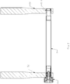
- the figure 1 shows in perspective view, the pin 1 for fixing the wheel on the bicycle frame, in particular to the rear dropouts of the frame if it is a rear wheel or to the fork dropouts, if it is a 'a front wheel. It consists of a rod 2, of longitudinal axis X, a first end 3 of which comprises a threaded portion 31 provided to cooperate with an internal thread formed in a first fork lug or of the frame.
- the second end 4 comprises in particular drive means 41 capable of transmitting a torque to the rod 2 and axial stop means provided to come to bear on an outer surface of a second fork or frame lug.
- the axial stop means 42 consist of an annular surface 83 oriented along a plane perpendicular to the longitudinal axis. It should be noted that the flat nature of the axial stop means is a direct consequence of the flat nature of the outer surface of the frame or fork lug on which these stop means rest. It is moreover also possible to envisage providing a conical embedding between the axial stop means and the surface of the fork dropout or of the frame.
- the annular surface of the stop means 42 is knurled in order to increase the coefficient of friction.
- the figure 2 shows a longitudinal sectional view of the spindle 1 when it is in place in a fork 5.
- the wheel and its hub have not been shown.
- the central shaft of the hub is located around the spindle 1 and the hub is held laterally between the two fork dropouts 51, 52.
- the second end of the spindle comprises torque limiting means 7 which are operational when the drive means rotate in the tightening direction.
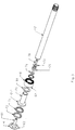
- the figure 3 shows an exploded perspective view, all the parts constituting the second end of the spindle.
- the rod 2 of the spindle is extended by a barrel 21 which is perfectly integral with it.
- the connection between the rod 2 and the barrel 21 can be made by gluing or any other means of securing.
- the end of the barrel 21 comprises a flange 211 which has on its front surface an external hexagon indentation. This external cavity is designed to receive, in a form engagement, a first cam ring 71.
- the cam ring 71, the barrel 21 and the rod are integral in rotation.
- the drive means 41 comprise a cap 6, the external face of which has an internal recess designed to receive an Allen key and the internal face of which includes an external recess with hexagon.
- This external cavity receives a second cam ring 72 integral in rotation with the cap 6.
- Each of the two cam rings 71 and 72 have a central opening of a shape complementary to that of the external indentations around which they are nested. These two rings are also juxtaposed and comprise respectively on each of their front face which face each other, a series of cams 77. This double plurality of cams 77 are oriented radially and are regularly distributed circumferentially. The cams 77 constitute a succession of radial ribs 73 which protrude from the end faces of the rings.
- the internal end of the cap 6 comprises a threaded shank 61 in which is inserted a screw 76 which, by means of a first support washer 73, constitutes a stopper for the spring 75 of the torque limiting device.
- the spring 75 is on the other hand held by a second support washer 74 placed inside the barrel 21.
- the spring 75 forces the cap 6 in the direction of the rod / barrel assembly and consequently, the two cam rings 71 and 72 against each other.
- These two cam rings 71 and 72 can be preferably identical and turned against one another, they can be easily obtained by sintering steel powder in order to obtain a precise, economical part, having great hardness and very good resistance to wear by being preferably self-lubricating by impregnation of grease.
- the cam rings are omitted and replaced by the placement of cams 77 directly on the cap 6, on the one hand, and on the barrel 21, on the other hand.
- a torque limiting device 65 is placed between the drive means 41 and the rod 2.
- the torque limiting device allows the breaking of the drive between the cap and the rod / barrel assembly.
- This device comprises the two cam rings 71 and 72 and a spring 75. It operates by cooperation between the cams of the two rings and by the stress exerted by the spring 75. As long as the tightening torque exerted by the user is relatively low, the two rings remain as close as possible to one another and the surfaces of cams of the second cam ring 72 and those of the first ring 71 are in contact. Then, the rotation of the cap 6, and of the second ring 72 which is integral with it, causes the rotation of the first ring 71 in the tightening direction. As the first ring 71 is integral with the barrel 21 and the rod 2, the threaded portion is then screwed into the fork lug. This relative position of the rings with respect to each other is designated as the “close” configuration.
- FIG 7 shows schematically how the two rings 71 and 72 cooperate when the cap 6 is driven in the screwing direction.
- View 7, as well as views 8 to 10 are partial schematic views which aim to explain the operation of the torque limiter and of the braking device.
- the succession of two adjacent ribs 73 of each of the two cam rings 71 and 72 are shown in a developed manner.
- the spring 75 forces the cap 6 and the first cam ring 71 into contact with the second cam ring 72.
- the cam surfaces 77 of the ribs 73 of each of the rings 71 and 72 remain in contact with each other.
- the torque limiting device described above is only one example among others of construction making it possible to limit the torque.
- the spindle of the invention further includes a braking device making it possible to ensure a friction differential between tightening and loosening.
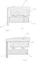
- the figure 4 shows a detail view in longitudinal section of the second end of the spindle in the free position, i.e. when the spindle is not tightened and therefore the axial stop means are not in contact with the fork dropout.
- the tightening torque which is exerted by the user by means of an Allen key inserted into the recess 62, is relatively low and it is transmitted directly to the rod via the second ring 72, then the first ring 71, then barrel 21.
- the torque exerted then ensures the axial progression of the spindle due to the screw / nut connection existing between the threaded end of the rod 2 and the internal thread 511 of the first fork leg 51.
- the axial stop means comprise a knurled surface so as to increase the coefficient of friction between the sleeve 8 and the second fork dropout 52.
- the device goes into the clamping configuration, proper. In fact, it is in this tightening configuration that the torque exerted by the user is, at least partially, converted into a clamping force for the hub of the wheel by bringing the two fork dropouts together.
- this sliding washer 90 will for example be made of thermoplastic with a low coefficient of friction.
- This predetermined value is between 3 and 20 N.m and preferably between 6 and 12 N.m.
- the torque limiting device if too much torque is exerted by the user, the cam surfaces which are in contact with each other will slide over each other. There is then a separation of the rings 71 and 72 which, when it reaches its maximum, separates the rotation of the cap 6 from the barrel / rod assembly. Under the effect of the cams sliding relative to each other, the rings leave the “close” configuration to put themselves in the “spread” configuration. During this phase, the spring 75 compresses, opposing the movement of the cams.
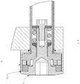
- the figure 6 represents the spindle in the tight configuration, that is to say in the configuration that it will occupy during the entire phase of use of the bicycle by the user and until the moment when the user wishes to remove the wheel from the frame .
- this braking device 81 aims to increase the torque necessary for the initiation of the release phase.
- the braking device 81 comprises two friction surfaces which are, on the one hand, the rear face 63 of the cap 6 and, on the other hand, the second end 82 of the sleeve 8.
- the knurled surface of the socket 8 is clamped against the surface of the fork dropout.
- the two rings Before the torque exerted by the user can be transmitted to the rod by means of the two rings, the latter must be in a respective angular configuration which allows it.
- the relative angular configuration of the rings for anti-clockwise drive (direction of loosening) is offset by the same angular difference with respect to the relative angular configuration allowing clockwise drive (direction tightening). Therefore, a rotation of the cap 6 is necessary before the torque exerted by the user can be transmitted to the rod 2.
- the angular difference between two adjacent ribs is 30 °, so that 'at the start of the tightening phase most of the torque transmitted by the user is consumed by the friction generated between the rear face 63 of the cap 6 and the second axial end 82 of the sleeve 8.
- the figure 10 shows the relative angular position of the two rings after the initial rotation of the cap in the direction of loosening until the bearing surfaces 78 come into contact with each other and the loosening torque exerted by the user is transmitted to the rod 2.
- the surface of the second axial end 82 of the sleeve and the rear face 63 of the cap are treated so as to maximize the coefficients of friction.
- the choices of material and surface treatment of the contact faces make it possible to guarantee that the torque required to initiate loosening is greater than 70% and preferably greater than 80% of the tightening torque required for optimum fixing of the wheel.
- the torque limiter tripping torque was calibrated to 8 Nm by having a spring 75 calibrated to a force threshold of 500 N (for this the cams have designed with an average propeller slope of 32.5 °).
- This additional friction torque here represents 12.5% of the tightening torque thus significantly increasing by 12.5% the ratio between loosening torque / tightening torque thus making it much easier to reach the threshold of 70% required by the standards. safety or even 85% thus guaranteeing a greater safety margin.
- the braking device is dimensioned such that the additional friction torque is greater than 5% and preferably greater than 10% of the value of the maximum tightening torque, ie. that is, the tripping torque of the torque limiter.
- the braking device of the invention does not require the installation of an additional part which could weigh down or make the end of the spindle more bulky.
- the various elements which constitute it and which contribute to its operation namely the socket 8, the cap 6 and the two rings are not exclusively dedicated to it.
- the socket 8, in this case, has first the function of being the outer body of the end 4 of the spindle.
- a torque limiting device makes it possible, during the mechanical design of the various parts constituting the spindle, to optimize the weight of the parts. This is in particular the case for the rod, the thickness of which may be minimal insofar as it cannot be subjected to excessive torsional stress.
- the torque limiter when the torque limiter is operational, the braking device is no longer operational. Indeed, the torque limiter is operational when the tightening torque exerted by the user approaches the tripping threshold, which immediately results in the separation of the two friction surfaces from one another, which, in fact, causes the braking device to be taken out of service.
Landscapes
- Engineering & Computer Science (AREA)
- Mechanical Engineering (AREA)
- General Engineering & Computer Science (AREA)
- Ocean & Marine Engineering (AREA)
- Axle Suspensions And Sidecars For Cycles (AREA)
- Braking Arrangements (AREA)
- One-Way And Automatic Clutches, And Combinations Of Different Clutches (AREA)
Claims (7)
- Spanndorn (1) für die Befestigung eines Fahrradrads an dem Rahmen eines Fahrrads, aufweisend eine Stange (2), die sich entlang einer Längsachse erstreckt und einen mittleren Teil hat, der von zwei Enden umrahmt ist, wobei das erste (3) der beiden Enden einen Gewindeabschnitt (31) aufweist, der mit einem in einem ersten Abschnitt des Rahmens des Fahrrads ausgeführten Innengewinde zusammenwirken kann, während das zweite Ende (4) mit Axialanschlagmitteln (42) versehen ist, die dazu vorgesehen sind, mit einem zweiten Abschnitt des Rahmens des Fahrrads in Kontakt zu kommen, sowie mit Antriebsmitteln (41), die dazu vorgesehen sind, einem Benutzer zu gestatten, alternativ ein Anzugsmoment oder ein Lösemoment auszuüben, wobei ein in Anzugsrichtung wirkender Drehmomentbegrenzer zwischen den Antriebsmitteln (41) und der Stange (2) platziert ist, dadurch gekennzeichnet, dass der Dorn (1) ferner eine Bremsvorrichtung (81) umfasst, die das zur Einleitung des Drehens der Antriebsmittel in der Löserichtung notwendige Moment erhöhen kann, wobei die Bremsvorrichtung (81) zwei Reibflächen umfasst, die miteinander in Kontakt stehen, wenn die Axialanschlagmittel (42) mit dem zweiten Rahmenabschnitt in Kontakt stehen, und dass der Drehmomentbegrenzer wirksam ist, wenn sich das durch den Benutzer ausgeübte Anzugsmoment der Auslöseschwelle nähert, was sich sofort dadurch äußert, dass sich die beiden Reibflächen voneinander entfernen, wodurch somit die Außerbetriebsetzung der Bremsvorrichtung hervorgerufen wird.
- Dorn nach Anspruch 1, dadurch gekennzeichnet, dass die Drehmomentbegrenzervorrichtung zwei nebeneinanderliegende Nockenringe (71, 72) umfasst, die bezüglich einander translationsmäßig entlang der Längsachse und drehungsmäßig entlang derselben Achse beweglich sind, und dass jeder der Ringe Nocken umfasst, durch die sich die axiale Relativposition der beiden Ringe zwischen einer "nahen" Position und einer "beabstandeten" Position verändern lässt.
- Spanndorn nach dem vorhergehenden Anspruch, dadurch gekennzeichnet, dass die Bremsvorrichtung (81) zwischen den Antriebsmitteln (41) und der Stange (2) platziert ist.
- Dorn nach dem vorhergehenden Anspruch, dadurch gekennzeichnet, dass die Bremsvorrichtung (81) eine zylindrische Hülse (8) umfasst, deren erstes axiales Ende (83) die Axialanschlagmittel (42) darstellt und deren zweites Ende (82) mit einer fest mit den Antriebsmitteln (41) verbundenen Fläche in Kontakt kommen kann.
- Dorn nach dem vorhergehenden Anspruch, dadurch gekennzeichnet, dass die axiale Länge der Hülse (8) derart ist, dass das zweite Ende der Hülse mit der fest mit den Antriebsmitteln (41) verbundenen Fläche in Kontakt steht, wenn die beiden Ringe des Drehmomentbegrenzers in der "nahen" Position sind, während das zweite Ende der Hülse nicht mit der Fläche in Kontakt steht, wenn die beiden Ringe in der "beabstandeten" Position sind.
- Dorn nach einem der vorhergehenden Ansprüche, dadurch gekennzeichnet, dass der Drehmomentbegrenzer einen Auslösewert zwischen 3 und 20 N.m, vorzugsweise zwischen 6 und 12 N.m, aufweist.
- Dorn nach dem vorhergehenden Anspruch, dadurch gekennzeichnet, dass die Bremsvorrichtung ein Reibmoment erzeugt, wenn der Benutzer die Lösephase einleitet, das mehr als 5%, vorzugsweise 10%, des Werts des Auslösemoments des Drehmomentbegrenzers beträgt.
Applications Claiming Priority (1)
| Application Number | Priority Date | Filing Date | Title |
|---|---|---|---|
| FR1770487A FR3066172B1 (fr) | 2017-05-12 | 2017-05-12 | Dispositif pour fixation d'une roue de cycle |
Publications (2)
| Publication Number | Publication Date |
|---|---|
| EP3401200A1 EP3401200A1 (de) | 2018-11-14 |
| EP3401200B1 true EP3401200B1 (de) | 2020-12-16 |
Family
ID=59153209
Family Applications (1)
| Application Number | Title | Priority Date | Filing Date |
|---|---|---|---|
| EP18171574.9A Active EP3401200B1 (de) | 2017-05-12 | 2018-05-09 | Vorrichtung zur befestigung eines laufrad |
Country Status (4)
| Country | Link |
|---|---|
| US (1) | US10730345B2 (de) |
| EP (1) | EP3401200B1 (de) |
| CN (1) | CN108860430A (de) |
| FR (1) | FR3066172B1 (de) |
Families Citing this family (1)
| Publication number | Priority date | Publication date | Assignee | Title |
|---|---|---|---|---|
| CN109551970B (zh) * | 2019-01-14 | 2024-05-17 | 义乌市风动科技有限公司 | 一种自行车轮固定结构 |
Family Cites Families (16)
| Publication number | Priority date | Publication date | Assignee | Title |
|---|---|---|---|---|
| CN2091781U (zh) * | 1991-02-25 | 1992-01-01 | 陈俊雄 | 一种自行车快卸安全装置 |
| FR2742193B1 (fr) | 1995-12-08 | 1998-02-27 | Mavic Sa | Axe de blocage rapide destine a etre utilise sur un cycle |
| US7562942B2 (en) * | 2005-12-22 | 2009-07-21 | Specialized Bicycle Components, Inc. | Bicycle wheel and release mechanism |
| US8042881B2 (en) * | 2007-05-16 | 2011-10-25 | Shimano Inc. | Bicycle wheel securing structure |
| ITMC20070108A1 (it) * | 2007-05-25 | 2008-11-26 | Marzocchi Spa | Perno ruota per cicli e motocicli provvisto di un dispositivo limitatore di coppia di serraggio. |
| FR2924641B1 (fr) | 2007-12-10 | 2010-03-19 | Salomon Sa | Systeme de serrage rapide pour cycle avec controle du couple de serrage |
| US9446626B2 (en) * | 2009-12-30 | 2016-09-20 | Raphael Schlanger | Vehicle wheel hub assembly |
| US10189305B2 (en) * | 2011-08-29 | 2019-01-29 | Sram, Llc | Bicycle front wheel hub with torque tube |
| FR2992624B1 (fr) * | 2012-06-27 | 2014-07-25 | Decathlon Sa | Systeme de fixation d’un accessoire sur un velo |
| JP2015071406A (ja) * | 2013-09-09 | 2015-04-16 | 株式会社シマノ | 自転車用車輪固定機構 |
| US9308961B2 (en) | 2013-11-27 | 2016-04-12 | Specialized Bicycle Components, Inc. | Bicycle frame with convertible dropouts |
| DE102014112084A1 (de) * | 2014-08-22 | 2016-02-25 | Dt Swiss Ag | Schnellspannvorrichtung |
| FR3037919B1 (fr) | 2015-06-29 | 2017-07-28 | Mavic Sas | Broche de fixation et moyeu pour roue de cycle |
| DE202015005524U1 (de) * | 2015-08-05 | 2015-10-02 | tune U. Fahl e.K. | Schnellverschluss für Fahrräder mit Justierfunktion |
| US10214263B2 (en) * | 2016-08-10 | 2019-02-26 | Chang Hui Lin | Angle adjustable quick release |
| TWI630142B (zh) * | 2017-06-14 | 2018-07-21 | 舜新金屬有限公司 | Quick release structure |
-
2017
- 2017-05-12 FR FR1770487A patent/FR3066172B1/fr not_active Expired - Fee Related
-
2018
- 2018-05-09 EP EP18171574.9A patent/EP3401200B1/de active Active
- 2018-05-11 US US15/977,623 patent/US10730345B2/en not_active Expired - Fee Related
- 2018-05-14 CN CN201810455556.8A patent/CN108860430A/zh active Pending
Non-Patent Citations (1)
| Title |
|---|
| None * |
Also Published As
| Publication number | Publication date |
|---|---|
| US20180327048A1 (en) | 2018-11-15 |
| CN108860430A (zh) | 2018-11-23 |
| US10730345B2 (en) | 2020-08-04 |
| FR3066172A1 (fr) | 2018-11-16 |
| EP3401200A1 (de) | 2018-11-14 |
| FR3066172B1 (fr) | 2020-11-06 |
Similar Documents
| Publication | Publication Date | Title |
|---|---|---|
| EP2070725B1 (de) | Schnellspannsystem für Rad mit Kontrolle des Spannmoments | |
| EP1380499B1 (de) | Fahrradpedal mit einstellbarer Axiallage | |
| EP2177373B1 (de) | Radlager-Montagevorrichtung und Fahrradnabe, die eine solche Vorrichtung einschließt | |
| EP3388252B1 (de) | Spannvorrichtung, insbesondere zum festziehen eines sattels auf einem fahrrad | |
| EP2496849B1 (de) | Selbstblockierende schraubfixiervorrichtung und anordnung damit | |
| EP2307258A2 (de) | Die verriegelung einer lenksäule unterstützende vorrichtung | |
| EP0402198B1 (de) | Verriegelungsmutter | |
| EP2520477B1 (de) | Schnellblockierachse zur Verwendung bei einem Fahrrad | |
| FR3039458A1 (fr) | Moyeu pour roue de cycle | |
| EP3401200B1 (de) | Vorrichtung zur befestigung eines laufrad | |
| FR2557656A1 (fr) | Dispositif amortisseur de torsion a organe elastique de centrage, notamment pour embrayage de vehicule automobile | |
| FR2678991A1 (fr) | Moyeu a roue libre pour cycles. | |
| FR2533283A1 (fr) | Moyeu a roue libre pour bicyclette | |
| FR3012543A1 (fr) | Ensemble de liaison par anneau d'arret pour troncon d'arbre | |
| FR2893303A1 (fr) | Pedalier de cycle | |
| FR2949138A1 (fr) | Turbomachine comportant des moyens d'anti-rotation d'un ecrou de palier | |
| EP4103855B1 (de) | Längsverstellbare zug-druck-stange mit widerstandsmomentvorrichtung | |
| EP2679478B1 (de) | Befestigungssystem eines Zubehörteils auf einem Fahrrad | |
| WO2021111072A1 (fr) | Engin de loisirs à guidon escamotable | |
| EP0314544B1 (de) | Spannfutter, insbesondere für Maschinen mit automatischem Vorschub | |
| EP0307327A1 (de) | Schraubverbindungensvorrichtung für zwei Elemente mit der Möglichkeit den Abstand dazwischen einzustellen | |
| FR2991410A1 (fr) | Ensemble de serrage a vis | |
| FR2998627A1 (fr) | Ecrou de securite autobloquant deverrouillable | |
| FR2781851A1 (fr) | Dispositif d'entrainement par pignons mene et menant | |
| FR2815928A1 (fr) | Assemblage d'une potence de bicyclette avec un pivot de fourche et un jeu de direction, potence et dispositif de reglage pour un tel assemblage |
Legal Events
| Date | Code | Title | Description |
|---|---|---|---|
| PUAI | Public reference made under article 153(3) epc to a published international application that has entered the european phase |
Free format text: ORIGINAL CODE: 0009012 |
|
| STAA | Information on the status of an ep patent application or granted ep patent |
Free format text: STATUS: THE APPLICATION HAS BEEN PUBLISHED |
|
| AK | Designated contracting states |
Kind code of ref document: A1 Designated state(s): AL AT BE BG CH CY CZ DE DK EE ES FI FR GB GR HR HU IE IS IT LI LT LU LV MC MK MT NL NO PL PT RO RS SE SI SK SM TR |
|
| AX | Request for extension of the european patent |
Extension state: BA ME |
|
| STAA | Information on the status of an ep patent application or granted ep patent |
Free format text: STATUS: REQUEST FOR EXAMINATION WAS MADE |
|
| 17P | Request for examination filed |
Effective date: 20190426 |
|
| STAA | Information on the status of an ep patent application or granted ep patent |
Free format text: STATUS: EXAMINATION IS IN PROGRESS |
|
| RIC1 | Information provided on ipc code assigned before grant |
Ipc: F16C 3/02 20060101ALI20191122BHEP Ipc: F16J 15/3256 20160101ALI20191122BHEP Ipc: B60B 27/02 20060101ALI20191122BHEP Ipc: B62K 25/02 20060101AFI20191122BHEP Ipc: B60B 35/08 20060101ALI20191122BHEP |
|
| 17Q | First examination report despatched |
Effective date: 20191219 |
|
| GRAP | Despatch of communication of intention to grant a patent |
Free format text: ORIGINAL CODE: EPIDOSNIGR1 |
|
| STAA | Information on the status of an ep patent application or granted ep patent |
Free format text: STATUS: GRANT OF PATENT IS INTENDED |
|
| INTG | Intention to grant announced |
Effective date: 20200714 |
|
| GRAS | Grant fee paid |
Free format text: ORIGINAL CODE: EPIDOSNIGR3 |
|
| GRAA | (expected) grant |
Free format text: ORIGINAL CODE: 0009210 |
|
| STAA | Information on the status of an ep patent application or granted ep patent |
Free format text: STATUS: THE PATENT HAS BEEN GRANTED |
|
| AK | Designated contracting states |
Kind code of ref document: B1 Designated state(s): AL AT BE BG CH CY CZ DE DK EE ES FI FR GB GR HR HU IE IS IT LI LT LU LV MC MK MT NL NO PL PT RO RS SE SI SK SM TR |
|
| REG | Reference to a national code |
Ref country code: GB Ref legal event code: FG4D Free format text: NOT ENGLISH |
|
| REG | Reference to a national code |
Ref country code: IE Ref legal event code: FG4D Free format text: LANGUAGE OF EP DOCUMENT: FRENCH |
|
| REG | Reference to a national code |
Ref country code: DE Ref legal event code: R096 Ref document number: 602018010763 Country of ref document: DE |
|
| REG | Reference to a national code |
Ref country code: AT Ref legal event code: REF Ref document number: 1345351 Country of ref document: AT Kind code of ref document: T Effective date: 20210115 |
|
| PG25 | Lapsed in a contracting state [announced via postgrant information from national office to epo] |
Ref country code: GR Free format text: LAPSE BECAUSE OF FAILURE TO SUBMIT A TRANSLATION OF THE DESCRIPTION OR TO PAY THE FEE WITHIN THE PRESCRIBED TIME-LIMIT Effective date: 20210317 Ref country code: NO Free format text: LAPSE BECAUSE OF FAILURE TO SUBMIT A TRANSLATION OF THE DESCRIPTION OR TO PAY THE FEE WITHIN THE PRESCRIBED TIME-LIMIT Effective date: 20210316 Ref country code: FI Free format text: LAPSE BECAUSE OF FAILURE TO SUBMIT A TRANSLATION OF THE DESCRIPTION OR TO PAY THE FEE WITHIN THE PRESCRIBED TIME-LIMIT Effective date: 20201216 Ref country code: RS Free format text: LAPSE BECAUSE OF FAILURE TO SUBMIT A TRANSLATION OF THE DESCRIPTION OR TO PAY THE FEE WITHIN THE PRESCRIBED TIME-LIMIT Effective date: 20201216 |
|
| REG | Reference to a national code |
Ref country code: AT Ref legal event code: MK05 Ref document number: 1345351 Country of ref document: AT Kind code of ref document: T Effective date: 20201216 |
|
| REG | Reference to a national code |
Ref country code: NL Ref legal event code: MP Effective date: 20201216 |
|
| PG25 | Lapsed in a contracting state [announced via postgrant information from national office to epo] |
Ref country code: SE Free format text: LAPSE BECAUSE OF FAILURE TO SUBMIT A TRANSLATION OF THE DESCRIPTION OR TO PAY THE FEE WITHIN THE PRESCRIBED TIME-LIMIT Effective date: 20201216 Ref country code: LV Free format text: LAPSE BECAUSE OF FAILURE TO SUBMIT A TRANSLATION OF THE DESCRIPTION OR TO PAY THE FEE WITHIN THE PRESCRIBED TIME-LIMIT Effective date: 20201216 Ref country code: BG Free format text: LAPSE BECAUSE OF FAILURE TO SUBMIT A TRANSLATION OF THE DESCRIPTION OR TO PAY THE FEE WITHIN THE PRESCRIBED TIME-LIMIT Effective date: 20210316 |
|
| PG25 | Lapsed in a contracting state [announced via postgrant information from national office to epo] |
Ref country code: HR Free format text: LAPSE BECAUSE OF FAILURE TO SUBMIT A TRANSLATION OF THE DESCRIPTION OR TO PAY THE FEE WITHIN THE PRESCRIBED TIME-LIMIT Effective date: 20201216 Ref country code: NL Free format text: LAPSE BECAUSE OF FAILURE TO SUBMIT A TRANSLATION OF THE DESCRIPTION OR TO PAY THE FEE WITHIN THE PRESCRIBED TIME-LIMIT Effective date: 20201216 |
|
| REG | Reference to a national code |
Ref country code: LT Ref legal event code: MG9D |
|
| PG25 | Lapsed in a contracting state [announced via postgrant information from national office to epo] |
Ref country code: EE Free format text: LAPSE BECAUSE OF FAILURE TO SUBMIT A TRANSLATION OF THE DESCRIPTION OR TO PAY THE FEE WITHIN THE PRESCRIBED TIME-LIMIT Effective date: 20201216 Ref country code: CZ Free format text: LAPSE BECAUSE OF FAILURE TO SUBMIT A TRANSLATION OF THE DESCRIPTION OR TO PAY THE FEE WITHIN THE PRESCRIBED TIME-LIMIT Effective date: 20201216 Ref country code: SM Free format text: LAPSE BECAUSE OF FAILURE TO SUBMIT A TRANSLATION OF THE DESCRIPTION OR TO PAY THE FEE WITHIN THE PRESCRIBED TIME-LIMIT Effective date: 20201216 Ref country code: PT Free format text: LAPSE BECAUSE OF FAILURE TO SUBMIT A TRANSLATION OF THE DESCRIPTION OR TO PAY THE FEE WITHIN THE PRESCRIBED TIME-LIMIT Effective date: 20210416 Ref country code: SK Free format text: LAPSE BECAUSE OF FAILURE TO SUBMIT A TRANSLATION OF THE DESCRIPTION OR TO PAY THE FEE WITHIN THE PRESCRIBED TIME-LIMIT Effective date: 20201216 Ref country code: RO Free format text: LAPSE BECAUSE OF FAILURE TO SUBMIT A TRANSLATION OF THE DESCRIPTION OR TO PAY THE FEE WITHIN THE PRESCRIBED TIME-LIMIT Effective date: 20201216 Ref country code: LT Free format text: LAPSE BECAUSE OF FAILURE TO SUBMIT A TRANSLATION OF THE DESCRIPTION OR TO PAY THE FEE WITHIN THE PRESCRIBED TIME-LIMIT Effective date: 20201216 |
|
| PG25 | Lapsed in a contracting state [announced via postgrant information from national office to epo] |
Ref country code: AT Free format text: LAPSE BECAUSE OF FAILURE TO SUBMIT A TRANSLATION OF THE DESCRIPTION OR TO PAY THE FEE WITHIN THE PRESCRIBED TIME-LIMIT Effective date: 20201216 Ref country code: PL Free format text: LAPSE BECAUSE OF FAILURE TO SUBMIT A TRANSLATION OF THE DESCRIPTION OR TO PAY THE FEE WITHIN THE PRESCRIBED TIME-LIMIT Effective date: 20201216 |
|
| REG | Reference to a national code |
Ref country code: DE Ref legal event code: R097 Ref document number: 602018010763 Country of ref document: DE |
|
| PG25 | Lapsed in a contracting state [announced via postgrant information from national office to epo] |
Ref country code: IS Free format text: LAPSE BECAUSE OF FAILURE TO SUBMIT A TRANSLATION OF THE DESCRIPTION OR TO PAY THE FEE WITHIN THE PRESCRIBED TIME-LIMIT Effective date: 20210416 |
|
| PLBE | No opposition filed within time limit |
Free format text: ORIGINAL CODE: 0009261 |
|
| STAA | Information on the status of an ep patent application or granted ep patent |
Free format text: STATUS: NO OPPOSITION FILED WITHIN TIME LIMIT |
|
| PG25 | Lapsed in a contracting state [announced via postgrant information from national office to epo] |
Ref country code: AL Free format text: LAPSE BECAUSE OF FAILURE TO SUBMIT A TRANSLATION OF THE DESCRIPTION OR TO PAY THE FEE WITHIN THE PRESCRIBED TIME-LIMIT Effective date: 20201216 Ref country code: IT Free format text: LAPSE BECAUSE OF FAILURE TO SUBMIT A TRANSLATION OF THE DESCRIPTION OR TO PAY THE FEE WITHIN THE PRESCRIBED TIME-LIMIT Effective date: 20201216 |
|
| 26N | No opposition filed |
Effective date: 20210917 |
|
| PG25 | Lapsed in a contracting state [announced via postgrant information from national office to epo] |
Ref country code: DK Free format text: LAPSE BECAUSE OF FAILURE TO SUBMIT A TRANSLATION OF THE DESCRIPTION OR TO PAY THE FEE WITHIN THE PRESCRIBED TIME-LIMIT Effective date: 20201216 |
|
| REG | Reference to a national code |
Ref country code: CH Ref legal event code: PL |
|
| PG25 | Lapsed in a contracting state [announced via postgrant information from national office to epo] |
Ref country code: CH Free format text: LAPSE BECAUSE OF NON-PAYMENT OF DUE FEES Effective date: 20210531 Ref country code: LI Free format text: LAPSE BECAUSE OF NON-PAYMENT OF DUE FEES Effective date: 20210531 Ref country code: MC Free format text: LAPSE BECAUSE OF FAILURE TO SUBMIT A TRANSLATION OF THE DESCRIPTION OR TO PAY THE FEE WITHIN THE PRESCRIBED TIME-LIMIT Effective date: 20201216 Ref country code: LU Free format text: LAPSE BECAUSE OF NON-PAYMENT OF DUE FEES Effective date: 20210509 Ref country code: ES Free format text: LAPSE BECAUSE OF FAILURE TO SUBMIT A TRANSLATION OF THE DESCRIPTION OR TO PAY THE FEE WITHIN THE PRESCRIBED TIME-LIMIT Effective date: 20201216 |
|
| REG | Reference to a national code |
Ref country code: BE Ref legal event code: MM Effective date: 20210531 |
|
| PG25 | Lapsed in a contracting state [announced via postgrant information from national office to epo] |
Ref country code: SI Free format text: LAPSE BECAUSE OF FAILURE TO SUBMIT A TRANSLATION OF THE DESCRIPTION OR TO PAY THE FEE WITHIN THE PRESCRIBED TIME-LIMIT Effective date: 20201216 |
|
| PG25 | Lapsed in a contracting state [announced via postgrant information from national office to epo] |
Ref country code: IE Free format text: LAPSE BECAUSE OF NON-PAYMENT OF DUE FEES Effective date: 20210509 |
|
| PG25 | Lapsed in a contracting state [announced via postgrant information from national office to epo] |
Ref country code: IS Free format text: LAPSE BECAUSE OF FAILURE TO SUBMIT A TRANSLATION OF THE DESCRIPTION OR TO PAY THE FEE WITHIN THE PRESCRIBED TIME-LIMIT Effective date: 20210416 |
|
| PG25 | Lapsed in a contracting state [announced via postgrant information from national office to epo] |
Ref country code: BE Free format text: LAPSE BECAUSE OF NON-PAYMENT OF DUE FEES Effective date: 20210531 |
|
| REG | Reference to a national code |
Ref country code: DE Ref legal event code: R081 Ref document number: 602018010763 Country of ref document: DE Owner name: MAVIC GROUP, FR Free format text: FORMER OWNER: MAVIC S.A.S., METZ-TESSY, FR |
|
| GBPC | Gb: european patent ceased through non-payment of renewal fee |
Effective date: 20220509 |
|
| PG25 | Lapsed in a contracting state [announced via postgrant information from national office to epo] |
Ref country code: GB Free format text: LAPSE BECAUSE OF NON-PAYMENT OF DUE FEES Effective date: 20220509 |
|
| PG25 | Lapsed in a contracting state [announced via postgrant information from national office to epo] |
Ref country code: CY Free format text: LAPSE BECAUSE OF FAILURE TO SUBMIT A TRANSLATION OF THE DESCRIPTION OR TO PAY THE FEE WITHIN THE PRESCRIBED TIME-LIMIT Effective date: 20201216 |
|
| PG25 | Lapsed in a contracting state [announced via postgrant information from national office to epo] |
Ref country code: HU Free format text: LAPSE BECAUSE OF FAILURE TO SUBMIT A TRANSLATION OF THE DESCRIPTION OR TO PAY THE FEE WITHIN THE PRESCRIBED TIME-LIMIT; INVALID AB INITIO Effective date: 20180509 |
|
| PG25 | Lapsed in a contracting state [announced via postgrant information from national office to epo] |
Ref country code: MK Free format text: LAPSE BECAUSE OF FAILURE TO SUBMIT A TRANSLATION OF THE DESCRIPTION OR TO PAY THE FEE WITHIN THE PRESCRIBED TIME-LIMIT Effective date: 20201216 |
|
| PG25 | Lapsed in a contracting state [announced via postgrant information from national office to epo] |
Ref country code: MT Free format text: LAPSE BECAUSE OF FAILURE TO SUBMIT A TRANSLATION OF THE DESCRIPTION OR TO PAY THE FEE WITHIN THE PRESCRIBED TIME-LIMIT Effective date: 20201216 |
|
| PGFP | Annual fee paid to national office [announced via postgrant information from national office to epo] |
Ref country code: DE Payment date: 20250521 Year of fee payment: 8 |
|
| PGFP | Annual fee paid to national office [announced via postgrant information from national office to epo] |
Ref country code: FR Payment date: 20250530 Year of fee payment: 8 |
|
| PG25 | Lapsed in a contracting state [announced via postgrant information from national office to epo] |
Ref country code: TR Free format text: LAPSE BECAUSE OF FAILURE TO SUBMIT A TRANSLATION OF THE DESCRIPTION OR TO PAY THE FEE WITHIN THE PRESCRIBED TIME-LIMIT Effective date: 20201216 |