EP3401207B1 - Systeme und verfahren für in ein flugzeug integrierte verbundrahmen - Google Patents
Systeme und verfahren für in ein flugzeug integrierte verbundrahmen Download PDFInfo
- Publication number
- EP3401207B1 EP3401207B1 EP18152595.7A EP18152595A EP3401207B1 EP 3401207 B1 EP3401207 B1 EP 3401207B1 EP 18152595 A EP18152595 A EP 18152595A EP 3401207 B1 EP3401207 B1 EP 3401207B1
- Authority
- EP
- European Patent Office
- Prior art keywords
- laminate composite
- composite structural
- structural beam
- aircraft
- wheel well
- Prior art date
- Legal status (The legal status is an assumption and is not a legal conclusion. Google has not performed a legal analysis and makes no representation as to the accuracy of the status listed.)
- Active
Links
Images


Classifications
-
- B—PERFORMING OPERATIONS; TRANSPORTING
- B32—LAYERED PRODUCTS
- B32B—LAYERED PRODUCTS, i.e. PRODUCTS BUILT-UP OF STRATA OF FLAT OR NON-FLAT, e.g. CELLULAR OR HONEYCOMB, FORM
- B32B5/00—Layered products characterised by the non- homogeneity or physical structure, i.e. comprising a fibrous, filamentary, particulate or foam layer; Layered products characterised by having a layer differing constitutionally or physically in different parts
- B32B5/02—Layered products characterised by the non- homogeneity or physical structure, i.e. comprising a fibrous, filamentary, particulate or foam layer; Layered products characterised by having a layer differing constitutionally or physically in different parts characterised by structural features of a fibrous or filamentary layer
-
- B—PERFORMING OPERATIONS; TRANSPORTING
- B64—AIRCRAFT; AVIATION; COSMONAUTICS
- B64C—AEROPLANES; HELICOPTERS
- B64C1/00—Fuselages; Constructional features common to fuselages, wings, stabilising surfaces or the like
- B64C1/06—Frames; Stringers; Longerons ; Fuselage sections
- B64C1/061—Frames
-
- B—PERFORMING OPERATIONS; TRANSPORTING
- B64—AIRCRAFT; AVIATION; COSMONAUTICS
- B64C—AEROPLANES; HELICOPTERS
- B64C1/00—Fuselages; Constructional features common to fuselages, wings, stabilising surfaces or the like
- B64C1/06—Frames; Stringers; Longerons ; Fuselage sections
- B64C1/12—Construction or attachment of skin panels
-
- B—PERFORMING OPERATIONS; TRANSPORTING
- B64—AIRCRAFT; AVIATION; COSMONAUTICS
- B64C—AEROPLANES; HELICOPTERS
- B64C1/00—Fuselages; Constructional features common to fuselages, wings, stabilising surfaces or the like
- B64C1/26—Attaching the wing or tail units or stabilising surfaces
-
- B—PERFORMING OPERATIONS; TRANSPORTING
- B64—AIRCRAFT; AVIATION; COSMONAUTICS
- B64F—GROUND OR AIRCRAFT-CARRIER-DECK INSTALLATIONS SPECIALLY ADAPTED FOR USE IN CONNECTION WITH AIRCRAFT; DESIGNING, MANUFACTURING, ASSEMBLING, CLEANING, MAINTAINING OR REPAIRING AIRCRAFT, NOT OTHERWISE PROVIDED FOR; HANDLING, TRANSPORTING, TESTING OR INSPECTING AIRCRAFT COMPONENTS, NOT OTHERWISE PROVIDED FOR
- B64F5/00—Designing, manufacturing, assembling, cleaning, maintaining or repairing aircraft, not otherwise provided for; Handling, transporting, testing or inspecting aircraft components, not otherwise provided for
- B64F5/10—Manufacturing or assembling aircraft, e.g. jigs therefor
-
- B—PERFORMING OPERATIONS; TRANSPORTING
- B32—LAYERED PRODUCTS
- B32B—LAYERED PRODUCTS, i.e. PRODUCTS BUILT-UP OF STRATA OF FLAT OR NON-FLAT, e.g. CELLULAR OR HONEYCOMB, FORM
- B32B2260/00—Layered product comprising an impregnated, embedded, or bonded layer wherein the layer comprises an impregnation, embedding, or binder material
- B32B2260/02—Composition of the impregnated, bonded or embedded layer
- B32B2260/021—Fibrous or filamentary layer
-
- B—PERFORMING OPERATIONS; TRANSPORTING
- B32—LAYERED PRODUCTS
- B32B—LAYERED PRODUCTS, i.e. PRODUCTS BUILT-UP OF STRATA OF FLAT OR NON-FLAT, e.g. CELLULAR OR HONEYCOMB, FORM
- B32B2260/00—Layered product comprising an impregnated, embedded, or bonded layer wherein the layer comprises an impregnation, embedding, or binder material
- B32B2260/04—Impregnation, embedding, or binder material
- B32B2260/046—Synthetic resin
-
- B—PERFORMING OPERATIONS; TRANSPORTING
- B32—LAYERED PRODUCTS
- B32B—LAYERED PRODUCTS, i.e. PRODUCTS BUILT-UP OF STRATA OF FLAT OR NON-FLAT, e.g. CELLULAR OR HONEYCOMB, FORM
- B32B2262/00—Composition or structural features of fibres which form a fibrous or filamentary layer or are present as additives
- B32B2262/10—Inorganic fibres
- B32B2262/106—Carbon fibres, e.g. graphite fibres
-
- B—PERFORMING OPERATIONS; TRANSPORTING
- B32—LAYERED PRODUCTS
- B32B—LAYERED PRODUCTS, i.e. PRODUCTS BUILT-UP OF STRATA OF FLAT OR NON-FLAT, e.g. CELLULAR OR HONEYCOMB, FORM
- B32B2605/00—Vehicles
- B32B2605/18—Aircraft
-
- B—PERFORMING OPERATIONS; TRANSPORTING
- B64—AIRCRAFT; AVIATION; COSMONAUTICS
- B64C—AEROPLANES; HELICOPTERS
- B64C1/00—Fuselages; Constructional features common to fuselages, wings, stabilising surfaces or the like
- B64C2001/0054—Fuselage structures substantially made from particular materials
- B64C2001/0072—Fuselage structures substantially made from particular materials from composite materials
-
- Y—GENERAL TAGGING OF NEW TECHNOLOGICAL DEVELOPMENTS; GENERAL TAGGING OF CROSS-SECTIONAL TECHNOLOGIES SPANNING OVER SEVERAL SECTIONS OF THE IPC; TECHNICAL SUBJECTS COVERED BY FORMER USPC CROSS-REFERENCE ART COLLECTIONS [XRACs] AND DIGESTS
- Y02—TECHNOLOGIES OR APPLICATIONS FOR MITIGATION OR ADAPTATION AGAINST CLIMATE CHANGE
- Y02T—CLIMATE CHANGE MITIGATION TECHNOLOGIES RELATED TO TRANSPORTATION
- Y02T50/00—Aeronautics or air transport
- Y02T50/40—Weight reduction
Definitions
- the disclosure relates generally to aircraft and more specifically to aircraft structures.
- Aircraft structures can be made from a variety of different materials.
- current composite aircraft structures can include structural beams within the nose wheel well assembly in the forward fuselage section of an aircraft fuselage that mixes composite beams with titanium shear-ties and aluminum plates.
- the multiple components of different materials are needed as current composite beams are required to be manufactured with constant web heights and so cannot be manufactured with complex geometries.
- additional parts made from other materials are needed for a full beam assembly.
- the multiple components lead to higher costs, tolerance stack-ups, further points of maintenance, and a less rigid structure.
- EP 2 695 726 A2 discloses a method and apparatus comprising a monolithic composite structure, a first edge of the monolithic composite structure, and a second edge of the monolithic composite structure.
- the first edge of the monolithic composite structure has a first shape configured to be connected to a structure in a vehicle.
- the second edge of the monolithic composite structure has a second shape configured to be connected to a body of the vehicle.
- US 2008/0179460 A1 discloses an invention that relates to an aircraft load frame made of a composite material, characterized in that it comprises two side elements and a base element, the side elements being joined at the inner part of the frame by means of the base element and each of the side elements comprising a leg joining the frame to the aircraft fuselage skin, a web and a lower flange joining the web and the base element.
- EP 2 722 145 A1 discloses an invention that provides a method for manufacturing a dry textile preform using two pairs of rollers forming respectively a first and second flange and comprising the steps of adjusting a difference between the rolling speed of the pair of first rollers and the rolling speed of the pair of second rollers to form a curvature radius of the fabric sheet depending on the adjusted difference; and adjusting the distance between the two pairs of rollers perpendicular to the movement direction of the fabric sheet to form a web portion between the first flange and the second flange, the web height depending on the adjusted distance.
- the method may be used to manufacture Z-shaped, U-shaped or C-shaped dry textile preforms used in the construction of reinforcement profiles for airborne vehicles.
- GB 2 134 059 A discloses a composite helicopter fuselage that comprises at least one main frame member having two generally vertical side beams joined by generally horizontal top and bottom beams.
- Each side beam comprises a top hat section bonded to a filler material and the top and bottom beams each comprise two channel sections arranged back to back and bonded to a filler material.
- An area at each end of the top and bottom beams is devoid of filler and the top hat sections of the side beams are slotted between the channel sections, the parts then being joined by bonding the internal surfaces of the channel sections to the external surfaces of the top hat sections.
- the fuselage is completed by panels attached to the external flanges of the side and top and bottom beams.
- DE 10 2014 116 270 B3 discloses a system for the continuous production of a curved profile preform from flat semi-finished fiber products, and a method for this, initially formed belt sections by a forming and then with the help of two rollers which are spaced from each other in the conveying direction.
- Buckingham R O ET AL "AUTOMATING THE MANUFACTURE OF COMPOSITE BROADGOODS", COMPOSITES, IPC BUSINESS PRESS LTD. HAYWARDS HEATH, GB, (19960301), vol. 27A, no. 3, ISSN 0010-4361, pages 191 - 200 , discloses the work completed under a three year European Commission research and development contract, entitled 'Integrating automatic handling of flexible materials, composite component design and quality assurance procedures'.
- the paper describes the reasons for conducting the work, the main drivers that shaped the final outcome, the key areas of study and the technical solution adopted, with a description of the system, tests conducted and a discussion of the achievements and future options.
- a machine was built that took prepreg material from a standard roll, through removal of the backing sheets, visual inspection, cutting, handling, layup and consolidation to form a multi-layer doubly curved component.
- variable height web composite frame beam is a laminate composite structural beam that includes a variable height web with a first flange on one end of the web, and a second flange on another portion of the web. At different portions of the variable height web composite frame beam, the first flange and the second flange are separated by different distances.
- certain aircraft structures are attached with a combination of beams, shear-ties, plates, and fasteners of different materials.
- Such combinations increase parts counts, allow for a greater amount of points of failure, decrease structural rigidity, and increase maintenance and assembly time.
- the laminate composite structural beam described herein allows for replacement of such combination of beams, shear-ties, plates, and fasteners with a single laminate composite structural beam.
- Fig. 1 illustrates a top view of an aircraft in accordance with an example of the disclosure.
- the aircraft 50 of Fig. 1 includes a fuselage 170, wings 172, horizontal stabilizers 174, aircraft propulsors 100A and 100B, and a vertical stabilizer 178.
- the aircraft 50 described in Fig. 1 is exemplary and it is appreciated that in other examples, the aircraft 50 may include less or additional components (e.g., no horizontal stabilizer, additional stabilizers, additional sensors, and/or additional controllers). Additionally, the structures and techniques described herein may be extended to other vehicles such as automobiles, watercrafts, and other aircrafts such as helicopters, Unmanned Aerial Vehicles, etc.
- the aircraft propulsors 100A and 100B can be any type of propulsor such as turbofans, turboprops, turbojets, ramjets, and/or any other type of propulsor that produces thrust to move the aircraft 50.
- the wings 172, horizontal stabilizers 174, and vertical stabilizer 178 can produce lift and/or control movement of the aircraft 50.
- Certain other examples of aircraft can include any number of aircraft propulsors, wings, horizontal stabilizers, and/or vertical stabilizers.
- the fuselage 170 is a fuselage that includes one or more composite beams. Certain other beams can also be composite or metallic (e.g., aluminum, titanium, steel, or another such metal).
- the fuselage 170 can, in certain examples, also include metallic and/or composite aircraft skin.
- the beams are coupled to the metallic skin, to each other, and/or to other components of the aircraft 50. At least some of the beams are used to form a load bearing structure of the aircraft 50.
- the fuselage 170 also includes wheel well openings 150A and 150B.
- the wheel well openings 150A and 150B are openings within the fuselage 170 that allow for landing gear and other components to be deployed. While certain beams of the fuselage 170 are continuous beams (e.g., they wrap around the inner circumference of a cross section of a section of the fuselage 170), other beams are discontinuous.
- the wheel well openings 150A and 150B can include one or more discontinuous laminate composite structural beams located proximate to the wheel well openings 150A and 150B. Such laminate composite structural beams are discontinuous due to the wheel well openings preventing the structural beams from fully wrapping around the circumference within the fuselage.
- the continuous and discontinuous laminate composite structural beams are illustrated in further detail in Fig. 2 .
- Fig. 2 illustrates a perspective view of an example aircraft structure in accordance with an example of the disclosure.
- Fig. 2 shows the aircraft structure from inside the fuselage looking outwards.
- Fig. 2 shows wheel well opening 150, discontinuous laminate composite structural beam 202, short beam 204, stringer 206, and continuous laminate composite structural beam 208.
- Discontinuous laminate composite structural beam 202, short beam 204, stringer 206, and continuous laminate composite structural beam 208 can form at least a portion of a structure of a fuselage (e.g., fuselage 170).
- a fuselage e.g., fuselage 170
- Various other examples of the fuselage can include one or more other structural components.
- the fuselage of an aircraft can be divided into a plurality of sections (e.g., divided into a plurality of lengthwise sections). Each section may include one or more continuous and/or discontinuous laminate composite structure beams to provide rigidity to the structure.
- the continuous laminate composite structural beam 208 can wrap around the inner circumference of a cross section of a portion of the fuselage.
- the discontinuous laminate composite structural beam 202 can, in certain examples, resemble an O shape.
- the continuous laminate composite structural beam 208 can be a continuous unbroken beam.
- Various examples of the continuous laminate composite structural beam 208 can be constructed from one component or a plurality (e.g., two, three, four, or five or more) of components. When the continuous laminate composite structural beam 208 is constructed from a plurality of components, the plurality of components may be coupled together via adhesives, welding, mechanical fasteners, and/or other such coupling techniques.
- the wheel well opening 150 can be wheel well opening 150A or 150B shown in Fig. 1 or another such wheel well opening. Due to the wheel well opening 150, structural beams in the section of the fuselage proximate to the wheel well opening 150 cannot be continuous as there is an opening within the circumference of the fuselage. As such, discontinuous laminate composite structural beam 202 is used in the section of the fuselage around wheel well opening 150.
- Discontinuous laminate composite structural beam 202 is a structural beam that wraps around a portion of the inner circumference of a cross section of the fuselage.
- the discontinuous laminate composite structural beam 202 can, in certain examples, resemble a C shape.
- the discontinuous portion of the discontinuous laminate composite structural beam 202 can accommodate the wheel well opening 150 and thus allow for deployment of landing gear and/or other components through the wheel well opening 150.
- discontinuous laminate composite structural beam 202 can be constructed from one component.
- the discontinuous laminate composite structural beam 202 can include variable web height. Such variable web height is described in further detail in Fig. 3 .
- the short beam 204 can be another structural beam of the fuselage.
- the short beam 204 is coupled to stringer 206 and the stringer 206 can be coupled to the discontinuous laminate composite structural beam 202 and/or continuous laminate composite structural beam 208 to form the structure of the fuselage.
- the stringer 206, the short beam 204, and/or the continuous laminate composite structural beam 208 can also include variable web heights.
- Fig. 3 illustrates an example of a variable web height aircraft composite structural beam.
- Fig. 3 shows the discontinuous laminate composite structural beam 202 of Fig. 2 .
- the discontinuous laminate composite structural beam 202 includes a variable height web 316, a first flange 312 located on a first end of the web, and a second flange 314 located on a second end of the web. At least a portion of the first flange 312 can be configured to conform to an inner portion of the fuselage of the aircraft so that the discontinuous laminate composite structural beam 202 can attach to the skin of the fuselage to provide structural support.
- the discontinuous laminate composite structural beam 202 is a single piece produced from a composite (e.g., a combination or one or more of carbon fiber, Kevlar, fiberglass, resin, and/or other synthetic composites).
- a composite e.g., a combination or one or more of carbon fiber, Kevlar, fiberglass, resin, and/or other synthetic composites.
- discontinuous laminate composite structural beam 202 includes distinct features such as variable height web 316, first flange 312, and second flange 314, such distinct features may all be part of one component that is laid up from one or more composite plies.
- the discontinuous laminate composite structural beam 202 includes a first portion 320 and a second portion 322.
- the variable height web 316 is a first height in the first portion 320, and is a second height different from the first height in the first portion 320. That is, the first flange 312 can be separated from the second flange 314 by a first distance in the first portion 320 and separated by a second distance in the second portion 322.
- the first portion and/or the second portion can include tapering parts within the portions of the web 316. That is, the height of the web 316 in such portions can change within the portion.
- Fig. 3 illustrates such an example as the first portion 320 tapers from one height to another height. However, though the first portion 320 tapers in Fig. 3 , the height of at least part of the first portion 320 is still different from the height of at least part of the second portion 322.
- Fig. 3 illustrates a discontinuous laminate composite structural beam 202 with a first portion and a second portion
- other examples of discontinuous laminate composite structural beams can include three or more portions and each of those portions can different heights. In certain other examples, at least two of those portions can be the same height (e.g., such an example would include portions of the ends of the discontinuous laminate composite structural beam that are the same height, but with a middle portion that is a different height).
- the first flange 312 and the second flange 314 can, in certain examples, be parts of the discontinuous laminate composite structural beam 202 that are arranged in an orientation different from that of the variable height web 316. That is, as shown in Fig. 3 , in a cross section of Fig.
- the major length of the first flange 312 and the second flange 314 are oriented approximately 90 degrees from that of the major length of variable height web 316 (e.g., the longer of the two sides that define the cross section of the web 316).
- Such an orientation can increase stiffness of the discontinuous laminate composite structural beam 202 and/or arrange certain surfaces of the discontinuous laminate composite structural beam 202 so that the discontinuous laminate composite structural beam 202 can be coupled to other portions of the aircraft.
- first flange 312, the second flange 314, and/or other flanges can orient in different orientations (e.g., oriented 30, 45, 60, 120, 135, or 150 degrees from the web 316) or include discontinuous laminate composite structural beams of other geometries.
- the discontinuous laminate composite structural beam can include 3-dimensionally varying geometry.
- the first flange 312 is located on an outer portion of the variable height web 316 and is configured to be installed on an aircraft closer to the aircraft fuselage than the second flange 314. As the variable height web 316 is curved, the first flange 312 can follow or substantially follow at least a portion of the curved portion of the variable height web 316. As such, the first flange 312 includes cut outs to allow for the first flange 312 to more easily bend to conform to the curvature of the variable height web 316. Other examples of the first flange 312 could not include such cut outs and the first flange 312 can then be constructed to bend along the curvature of the variable height web 316 via robotic clamp arc forming. Robotic clamp arc forming is described in further detail in Fig. 5 .
- the second flange 314 is located on an inner portion of the variable height web 316.
- the second flange 314 can also follow or substantially follow at least a portion of the curved portion of the variable height web 316.
- the second flange 314 is unbroken (e.g., does not include the cut outs of first flange 312), but other examples of the second flange 314 can include cut outs.
- Figs. 4A-C illustrate examples of an aircraft wheel well composite structure.
- the discontinuous laminate composite structural beam 202 can be coupled to one or more wheel well beams to further define a wheel well. Coupling the discontinuous laminate composite structural beam 202 to one or more wheel well beams can allow for the volume of the wheel well that contains the landing gear when the landing gear is in the retracted position to be defined.
- Figs. 4A-C illustrate three such example wheel well beams. As shown in Figs. 4A-C , each discontinuous laminate composite structural beam 202 in Figs. 4A-C is coupled to a wheel well beam that defines the vertical portion of the wheel well.
- the discontinuous laminate composite structural beam 202 is coupled to wheel well beam 430.
- Wheel well beam 430 is configured to be disposed on top of the variable height web of the discontinuous laminate composite structural beam 202.
- the discontinuous laminate composite structural beam 202 is coupled to wheel well beam 432.
- Wheel well beam 432 is configured to be disposed adjacent to an end of the discontinuous laminate composite structural beam 202.
- the discontinuous laminate composite structural beam 202 is coupled to wheel well beam 434.
- the wheel well beam 434 is configured to be disposed both on top of and adjacent to an end of the discontinuous laminate composite structural beam 202.
- the wheel well beam 434 additionally includes ribs and features that locate the wheel well beam 434 relative to the discontinuous laminate composite structural beam 202 to ensure correct positioning of the wheel well beam 434 relative to the discontinuous laminate composite structural beam 202.
- Figs. 4A-C describe wheel well beams that are separate components from that of the discontinuous laminate composite structural beam 202
- the discontinuous laminate composite structural beam 202 and the wheel well beam are one component (e.g., manufactured via, for example, robotic clamp arc forming) to allow for a combined discontinuous laminate composite structural beam 202 and wheel well beam that includes variable web heights.
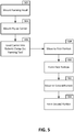
- Fig. 5 is a flowchart detailing production of a variable web height aircraft composite structural beam in accordance with an example of the disclosure.
- a forming head is mounted on a robot, robotic arm, or a portion thereof.
- a nosepiece configured to substantially match or form one or more local contours of a portion of the variable web height aircraft composite structural beam can also be attached to the forming head.
- One or more plies that form the variable web height aircraft composite structural beam are placed in a designated position on a ply carrier in block 504.
- the ply carrier is then loaded onto the robotic clamp arc forming tool.
- the ply carrier is then ready for layup, forming, and compaction operations.
- a portion of the robot, robotic arm, and/or tool is moved to a first portion of the variable web height aircraft composite structural beam to form the first portion or a feature of the first portion in block 510.
- the ply or plies are swept over a section of the tool to move the forming head over the tool to form a curvature of the first portion.
- the portion of the robot, robotic arm, and/or tool is then moved to a second portion of the variable web height aircraft composite structural beam in block 512 to form the second portion or a feature of the second portion in block 514.
- the first portion and the second portion can include different or variable web heights.
Landscapes
- Engineering & Computer Science (AREA)
- Aviation & Aerospace Engineering (AREA)
- Mechanical Engineering (AREA)
- Manufacturing & Machinery (AREA)
- Transportation (AREA)
- Moulding By Coating Moulds (AREA)
- Laminated Bodies (AREA)
Claims (9)
- Flugzeug, aufweisend:
einen Rumpf (170), aufweisend mindestens einen Verbundrahmenträger mit einem Steg variabler Höhe, wobei der Verbundrahmenträger mit einem Steg variabler Höhe ein Strukturträger aus einem Schichtverbund ist, aufweisend:einen Steg (316) mit variabler Höhe;einen ersten Flansch (312), der sich an einem äußeren Abschnitt des Stegs befindet;einen zweiten Flansch (314), der sich an einem inneren Abschnitt des Stegs befindet, wobei der erste Flansch und der zweite Flansch durch einen ersten Abstand an einem ersten Abschnitt (320) des Strukturträgers aus einem Schichtverbund und durch einen zweiten Abstand an einem zweiten Abschnitt (322) des Strukturträgers aus einem Schichtverbund getrennt sind;wobei der Strukturträger aus einem Schichtverbund dazu konfiguriert ist, benachbart zu einer Fahrwerkschacht-Öffnung (150) eines Flugzeugs angeordnet zu werden;wobei von dem Strukturträger aus einem Schichtverbund der erste Abstand größer als der zweite Abstand ist, wobei der erste Abschnitt des Strukturträgers aus einem Schichtverbund an die Fahrwerkschacht-Öffnung des Rumpfs angrenzt, und wobei der zweite Abschnitt des Strukturträgers aus einem Schichtverbund weiter von der Fahrwerkschacht-Öffnung angeordnet ist als der erste Abschnitt des Strukturträgers aus einem Schichtverbund; undwobei der Strukturträger aus einem Schichtverbund ein diskontinuierlicher Träger (202) ist und ferner ein erstes Ende aufweist, das in der Nähe des ersten Abschnitts des Strukturträgers aus einem Schichtverbund angeordnet ist, und der Rumpf ferner einen Fahrwerkschacht-Träger (430, 432, 434) aufweist, der mit dem ersten Ende verbunden ist,wobei der Fahrwerkschacht-Träger ferner einen vertikalen Abschnitt des Fahrwerkschachts definiert und wobei ferner der diskontinuierliche Strukturträger aus einem Schichtverbund und der Fahrwerkschacht-Träger eine Komponente sind. - Flugzeug nach Anspruch 1,
wobei der Rumpf ferner einen kontinuierlichen Strukturträger (208) aus einem Schichtverbund aufweist. - Flugzeug nach Anspruch 1 bis 2, wobei der Rumpf ferner eine Rumpfhaut aufweist und mindestens ein Abschnitt des ersten Flansches einem inneren Abschnitt der Rumpfhaut entspricht.
- Flugzeug nach Anspruch 1 bis 3, wobei der Strukturträger aus einem Schichtverbund sanft zwischen dem ersten Abschnitt des diskontinuierlichen Strukturträgers aus einem Schichtverbund und dem zweiten Abschnitt des diskontinuierlichen Strukturträgers aus einem Schichtverbund übergeht.
- Flugzeug nach Anspruch 1 bis 4, wobei der diskontinuierliche Strukturträger aus einem Schichtverbund Kohlenstofffaser und Harz aufweist.
- Flugzeug nach Anspruch 1 bis 5, ferner aufweisend:einen Flügel (172), der mit dem Rumpf verbunden ist undeine Flugzeugs-Antriebsvorrichtung (100), die mit dem Flügel und/oder dem Rumpf verbunden ist.
- Verfahren, aufweisend:Montieren einer Lage auf einem Lagenträger;Einlegen des Lagenträgers in ein robotergesteuertes bogenausbildendes Spannwerkzeug;Bewegen eines Formkopfs des robotergesteuerten bogenausbildenden Spannwerkzeugs zu einem ersten Abschnitt (320) der Lage, wobei die Lage mindestens eine Schicht eines Flugzeug-Strukturträgers aus einem Schichtverbund ausbildet, und wobei der Flugzeug-Strukturträger aus einem Schichtverbund einen Steg (316) variabler Höhe, einen ersten Flansch (312), der an einem äußeren Abschnitt des Stegs angeordnet ist, und einen zweiten Flansch (314), der an einem inneren Abschnitt des Stegs angeordnet ist, aufweist;Ausbilden der Lage an dem ersten Abschnitt, und wobei der erste Flansch und der zweite Flansch durch einen ersten Abstand an dem ersten Abschnitt der Lage getrennt sind;Bewegen des Formkopfs zu einem zweiten Abschnitt (322) der Lage undAusbilden der Lage an dem zweiten Abschnitt, wobei der erste Flansch und der zweite Flansch durch einen zweiten Abstand an dem zweiten Abschnitt der Lage getrennt sind;wobei der Strukturträger aus einem Schichtverbund dazu konfiguriert ist, benachbart zu einer Fahrwerkschachts-Öffnung (150) eines Flugzeugs angeordnet zu werden;wobei von dem Strukturträger aus einem Schichtverbund der erste Abstand größer als der zweite Abstand ist, wobei der erste Abschnitt der Lage an die Fahrwerksschacht-Öffnung des Rumpfes angrenzt, und wobei der zweite Abschnitt der Lage weiter von der Fahrwerkschachts-Öffnung angeordnet ist als der erste Abschnitt der Lage; undwobei der Strukturträger aus einem Schichtverbund ein diskontinuierlicher Träger (202) ist und ferner ein erstes Ende aufweist, das in der Nähe des ersten Abschnitts der Lage angeordnet ist, und der Rumpf ferner einen Fahrwerkschachts-Träger (430, 432, 434) aufweist, der mit dem ersten Ende verbunden ist,wobei der Fahrwerkschachts-Träger ferner einen vertikalen Abschnitt des Fahrwerkschachts definiert und wobei ferner der diskontinuierliche Strukturträger aus einem Schichtverbund und der Fahrwerkschachts-Träger eine Komponente sind.
- Verfahren nach Anspruch 7, ferner aufweisend:
Koppeln des Formkopfs mit dem robotergesteuerten bogenausbildenden Spannwerkzeug. - Verfahren nach Anspruch 7 bis 8, wobei die Lage eine Lage aus Verbundharz ist.
Applications Claiming Priority (1)
| Application Number | Priority Date | Filing Date | Title |
|---|---|---|---|
| US15/592,124 US20180327071A1 (en) | 2017-05-10 | 2017-05-10 | Systems and methods for aircraft integrated composite frames |
Publications (2)
| Publication Number | Publication Date |
|---|---|
| EP3401207A1 EP3401207A1 (de) | 2018-11-14 |
| EP3401207B1 true EP3401207B1 (de) | 2020-06-10 |
Family
ID=61007609
Family Applications (1)
| Application Number | Title | Priority Date | Filing Date |
|---|---|---|---|
| EP18152595.7A Active EP3401207B1 (de) | 2017-05-10 | 2018-01-19 | Systeme und verfahren für in ein flugzeug integrierte verbundrahmen |
Country Status (3)
| Country | Link |
|---|---|
| US (1) | US20180327071A1 (de) |
| EP (1) | EP3401207B1 (de) |
| ES (1) | ES2815473T3 (de) |
Family Cites Families (14)
| Publication number | Priority date | Publication date | Assignee | Title |
|---|---|---|---|---|
| GB2134059B (en) * | 1983-01-25 | 1986-06-25 | Westland Plc | Composite helicopter fuselage |
| FR2632604B1 (fr) * | 1988-06-08 | 1991-07-12 | Aerospatiale | Cadre en materiau composite notamment pour fuselage d'aeronef, et son procede de fabrication |
| EP2128018A4 (de) * | 2007-01-29 | 2013-09-18 | Airbus Operations Sl | Flugzeuglastrahmen aus verbundmaterial |
| FR2917369B1 (fr) * | 2007-06-15 | 2009-08-07 | Airbus France Sas | Case de train d'atterrissage a encombrement reduit |
| US7641146B2 (en) * | 2007-09-24 | 2010-01-05 | The Boeing Company | Aircraft nose landing gear enclosure |
| US8296923B2 (en) * | 2007-11-29 | 2012-10-30 | Spirit Aerosystems, Inc. | Modular numerically controlled system |
| US8349105B2 (en) * | 2008-04-17 | 2013-01-08 | The Boeing Company | Curved composite frames and method of making the same |
| KR101030226B1 (ko) * | 2010-06-11 | 2011-04-22 | 주식회사 스틸플라워 | 다중 복합곡면 성형판 제조방법 |
| US8551380B2 (en) | 2010-11-12 | 2013-10-08 | The Boeing Company | Method of laying up prepreg plies on contoured tools using a deformable carrier film |
| FR2983825B1 (fr) * | 2011-12-12 | 2014-01-10 | Airbus Operations Sas | Structure avant d'avion et de case de rangement de train d'atterrissage avant |
| US10099765B2 (en) * | 2012-08-08 | 2018-10-16 | The Boeing Company | Monolithic composite structures for vehicles |
| EP2722145B1 (de) * | 2012-10-17 | 2016-02-24 | Airbus Operations GmbH | Verfahren und Vorrichtung zur Herstellung einer trockenen Textilien-Vorform |
| US9314974B2 (en) | 2013-01-07 | 2016-04-19 | The Boeing Company | Method and apparatus for fabricating contoured laminate structures |
| DE102014116270B3 (de) * | 2014-11-07 | 2016-01-21 | Deutsches Zentrum für Luft- und Raumfahrt e.V. | Anlage und Verfahren zur kontinuierlichen Herstellung gekrümmter Preformen |
-
2017
- 2017-05-10 US US15/592,124 patent/US20180327071A1/en not_active Abandoned
-
2018
- 2018-01-19 EP EP18152595.7A patent/EP3401207B1/de active Active
- 2018-01-19 ES ES18152595T patent/ES2815473T3/es active Active
Non-Patent Citations (1)
| Title |
|---|
| None * |
Also Published As
| Publication number | Publication date |
|---|---|
| EP3401207A1 (de) | 2018-11-14 |
| ES2815473T3 (es) | 2021-03-30 |
| US20180327071A1 (en) | 2018-11-15 |
Similar Documents
| Publication | Publication Date | Title |
|---|---|---|
| EP3030413B1 (de) | Versteifte verbundplatten und verfahren zu deren herstellung | |
| EP3301014B1 (de) | Tragflächenförmiger körper mit hülle auf verbundstoffbasis mit integriertem hutförmigen holm | |
| EP3012080B1 (de) | Formwerkzeug und verfahren zum formen von verbundmaterial | |
| EP2571757B1 (de) | Ausschnitt an dem ende eines stringers aus verbundwerkstoff | |
| US8088236B2 (en) | Apparatus and method for producing a large-area fibre-composite structural component | |
| EP3031711B1 (de) | Flugzeugrahmen für zur heckanschlagwinkelverbesserung | |
| EP3415308B1 (de) | Verfahren zur montage eines flugzeugrumpfes | |
| CN107757873B (zh) | 用于在结构上支撑飞机机翼的系统和方法 | |
| EP3173334B1 (de) | Sitzschienen mit verbundstoffrahmen | |
| CN101360647A (zh) | 具有近似椭圆横截面的重量优化可加压飞行器机身结构 | |
| EP3483057B1 (de) | Verstärkungsanordnung für eine öffnung in einer flugzeugstruktur | |
| US8740151B1 (en) | Adjustable splice fitting for shimless connection of structual members | |
| EP3078585B1 (de) | Rippenstruktur und verfahren zur formung davon | |
| EP3501971A1 (de) | Flugzeugheckrumpfabschnitt und herstellungsverfahren dafür | |
| US9701393B2 (en) | Highly integrated inner structure of a torsion box of an aircraft lifting surface | |
| EP3401207B1 (de) | Systeme und verfahren für in ein flugzeug integrierte verbundrahmen | |
| EP4140718A1 (de) | Vorrichtung und verfahren zur ermöglichung von biegung in der ebene von verbundstrukturen hoher kontur in nachformungsvorgängen | |
| EP3549853A1 (de) | Flugzeugrumpf mit kompositvorformling | |
| EP2848518B1 (de) | Kohlenstofffaserverstärkter Polymerladebalken mit integrierten Frachtstützen und C-Verbindungsstellen | |
| US11383820B2 (en) | Aerodynamic surface lap splice | |
| EP2982598A2 (de) | Seitliches lagen-layup eines verbundholms | |
| EP3275778B1 (de) | Systeme für reparaturen am gekrümmten flugzeugunterstrukturen und verfahren | |
| US11685503B2 (en) | Stringer assemblies and methods of forming thereof | |
| US12459221B2 (en) | Method for producing a torsion box for a structure of an airplane and a torsion box for a structure of an airplane |
Legal Events
| Date | Code | Title | Description |
|---|---|---|---|
| PUAI | Public reference made under article 153(3) epc to a published international application that has entered the european phase |
Free format text: ORIGINAL CODE: 0009012 |
|
| STAA | Information on the status of an ep patent application or granted ep patent |
Free format text: STATUS: REQUEST FOR EXAMINATION WAS MADE |
|
| 17P | Request for examination filed |
Effective date: 20180119 |
|
| AK | Designated contracting states |
Kind code of ref document: A1 Designated state(s): AL AT BE BG CH CY CZ DE DK EE ES FI FR GB GR HR HU IE IS IT LI LT LU LV MC MK MT NL NO PL PT RO RS SE SI SK SM TR |
|
| AX | Request for extension of the european patent |
Extension state: BA ME |
|
| GRAP | Despatch of communication of intention to grant a patent |
Free format text: ORIGINAL CODE: EPIDOSNIGR1 |
|
| STAA | Information on the status of an ep patent application or granted ep patent |
Free format text: STATUS: GRANT OF PATENT IS INTENDED |
|
| INTG | Intention to grant announced |
Effective date: 20191022 |
|
| GRAJ | Information related to disapproval of communication of intention to grant by the applicant or resumption of examination proceedings by the epo deleted |
Free format text: ORIGINAL CODE: EPIDOSDIGR1 |
|
| STAA | Information on the status of an ep patent application or granted ep patent |
Free format text: STATUS: REQUEST FOR EXAMINATION WAS MADE |
|
| GRAP | Despatch of communication of intention to grant a patent |
Free format text: ORIGINAL CODE: EPIDOSNIGR1 |
|
| STAA | Information on the status of an ep patent application or granted ep patent |
Free format text: STATUS: GRANT OF PATENT IS INTENDED |
|
| INTC | Intention to grant announced (deleted) | ||
| INTG | Intention to grant announced |
Effective date: 20200401 |
|
| GRAS | Grant fee paid |
Free format text: ORIGINAL CODE: EPIDOSNIGR3 |
|
| GRAA | (expected) grant |
Free format text: ORIGINAL CODE: 0009210 |
|
| STAA | Information on the status of an ep patent application or granted ep patent |
Free format text: STATUS: THE PATENT HAS BEEN GRANTED |
|
| AK | Designated contracting states |
Kind code of ref document: B1 Designated state(s): AL AT BE BG CH CY CZ DE DK EE ES FI FR GB GR HR HU IE IS IT LI LT LU LV MC MK MT NL NO PL PT RO RS SE SI SK SM TR |
|
| REG | Reference to a national code |
Ref country code: GB Ref legal event code: FG4D |
|
| REG | Reference to a national code |
Ref country code: AT Ref legal event code: REF Ref document number: 1278973 Country of ref document: AT Kind code of ref document: T Effective date: 20200615 Ref country code: CH Ref legal event code: EP |
|
| REG | Reference to a national code |
Ref country code: DE Ref legal event code: R096 Ref document number: 602018005106 Country of ref document: DE |
|
| REG | Reference to a national code |
Ref country code: IE Ref legal event code: FG4D |
|
| REG | Reference to a national code |
Ref country code: LT Ref legal event code: MG4D |
|
| PG25 | Lapsed in a contracting state [announced via postgrant information from national office to epo] |
Ref country code: FI Free format text: LAPSE BECAUSE OF FAILURE TO SUBMIT A TRANSLATION OF THE DESCRIPTION OR TO PAY THE FEE WITHIN THE PRESCRIBED TIME-LIMIT Effective date: 20200610 Ref country code: SE Free format text: LAPSE BECAUSE OF FAILURE TO SUBMIT A TRANSLATION OF THE DESCRIPTION OR TO PAY THE FEE WITHIN THE PRESCRIBED TIME-LIMIT Effective date: 20200610 Ref country code: LT Free format text: LAPSE BECAUSE OF FAILURE TO SUBMIT A TRANSLATION OF THE DESCRIPTION OR TO PAY THE FEE WITHIN THE PRESCRIBED TIME-LIMIT Effective date: 20200610 Ref country code: GR Free format text: LAPSE BECAUSE OF FAILURE TO SUBMIT A TRANSLATION OF THE DESCRIPTION OR TO PAY THE FEE WITHIN THE PRESCRIBED TIME-LIMIT Effective date: 20200911 Ref country code: NO Free format text: LAPSE BECAUSE OF FAILURE TO SUBMIT A TRANSLATION OF THE DESCRIPTION OR TO PAY THE FEE WITHIN THE PRESCRIBED TIME-LIMIT Effective date: 20200910 |
|
| REG | Reference to a national code |
Ref country code: NL Ref legal event code: MP Effective date: 20200610 |
|
| PG25 | Lapsed in a contracting state [announced via postgrant information from national office to epo] |
Ref country code: BG Free format text: LAPSE BECAUSE OF FAILURE TO SUBMIT A TRANSLATION OF THE DESCRIPTION OR TO PAY THE FEE WITHIN THE PRESCRIBED TIME-LIMIT Effective date: 20200910 Ref country code: LV Free format text: LAPSE BECAUSE OF FAILURE TO SUBMIT A TRANSLATION OF THE DESCRIPTION OR TO PAY THE FEE WITHIN THE PRESCRIBED TIME-LIMIT Effective date: 20200610 Ref country code: HR Free format text: LAPSE BECAUSE OF FAILURE TO SUBMIT A TRANSLATION OF THE DESCRIPTION OR TO PAY THE FEE WITHIN THE PRESCRIBED TIME-LIMIT Effective date: 20200610 Ref country code: RS Free format text: LAPSE BECAUSE OF FAILURE TO SUBMIT A TRANSLATION OF THE DESCRIPTION OR TO PAY THE FEE WITHIN THE PRESCRIBED TIME-LIMIT Effective date: 20200610 |
|
| REG | Reference to a national code |
Ref country code: AT Ref legal event code: MK05 Ref document number: 1278973 Country of ref document: AT Kind code of ref document: T Effective date: 20200610 |
|
| PG25 | Lapsed in a contracting state [announced via postgrant information from national office to epo] |
Ref country code: NL Free format text: LAPSE BECAUSE OF FAILURE TO SUBMIT A TRANSLATION OF THE DESCRIPTION OR TO PAY THE FEE WITHIN THE PRESCRIBED TIME-LIMIT Effective date: 20200610 Ref country code: AL Free format text: LAPSE BECAUSE OF FAILURE TO SUBMIT A TRANSLATION OF THE DESCRIPTION OR TO PAY THE FEE WITHIN THE PRESCRIBED TIME-LIMIT Effective date: 20200610 |
|
| PG25 | Lapsed in a contracting state [announced via postgrant information from national office to epo] |
Ref country code: PT Free format text: LAPSE BECAUSE OF FAILURE TO SUBMIT A TRANSLATION OF THE DESCRIPTION OR TO PAY THE FEE WITHIN THE PRESCRIBED TIME-LIMIT Effective date: 20201012 Ref country code: RO Free format text: LAPSE BECAUSE OF FAILURE TO SUBMIT A TRANSLATION OF THE DESCRIPTION OR TO PAY THE FEE WITHIN THE PRESCRIBED TIME-LIMIT Effective date: 20200610 Ref country code: CZ Free format text: LAPSE BECAUSE OF FAILURE TO SUBMIT A TRANSLATION OF THE DESCRIPTION OR TO PAY THE FEE WITHIN THE PRESCRIBED TIME-LIMIT Effective date: 20200610 Ref country code: AT Free format text: LAPSE BECAUSE OF FAILURE TO SUBMIT A TRANSLATION OF THE DESCRIPTION OR TO PAY THE FEE WITHIN THE PRESCRIBED TIME-LIMIT Effective date: 20200610 Ref country code: EE Free format text: LAPSE BECAUSE OF FAILURE TO SUBMIT A TRANSLATION OF THE DESCRIPTION OR TO PAY THE FEE WITHIN THE PRESCRIBED TIME-LIMIT Effective date: 20200610 Ref country code: SM Free format text: LAPSE BECAUSE OF FAILURE TO SUBMIT A TRANSLATION OF THE DESCRIPTION OR TO PAY THE FEE WITHIN THE PRESCRIBED TIME-LIMIT Effective date: 20200610 |
|
| PG25 | Lapsed in a contracting state [announced via postgrant information from national office to epo] |
Ref country code: IS Free format text: LAPSE BECAUSE OF FAILURE TO SUBMIT A TRANSLATION OF THE DESCRIPTION OR TO PAY THE FEE WITHIN THE PRESCRIBED TIME-LIMIT Effective date: 20201010 Ref country code: PL Free format text: LAPSE BECAUSE OF FAILURE TO SUBMIT A TRANSLATION OF THE DESCRIPTION OR TO PAY THE FEE WITHIN THE PRESCRIBED TIME-LIMIT Effective date: 20200610 Ref country code: SK Free format text: LAPSE BECAUSE OF FAILURE TO SUBMIT A TRANSLATION OF THE DESCRIPTION OR TO PAY THE FEE WITHIN THE PRESCRIBED TIME-LIMIT Effective date: 20200610 |
|
| REG | Reference to a national code |
Ref country code: DE Ref legal event code: R097 Ref document number: 602018005106 Country of ref document: DE |
|
| REG | Reference to a national code |
Ref country code: ES Ref legal event code: FG2A Ref document number: 2815473 Country of ref document: ES Kind code of ref document: T3 Effective date: 20210330 |
|
| PLBE | No opposition filed within time limit |
Free format text: ORIGINAL CODE: 0009261 |
|
| STAA | Information on the status of an ep patent application or granted ep patent |
Free format text: STATUS: NO OPPOSITION FILED WITHIN TIME LIMIT |
|
| PG25 | Lapsed in a contracting state [announced via postgrant information from national office to epo] |
Ref country code: DK Free format text: LAPSE BECAUSE OF FAILURE TO SUBMIT A TRANSLATION OF THE DESCRIPTION OR TO PAY THE FEE WITHIN THE PRESCRIBED TIME-LIMIT Effective date: 20200610 |
|
| 26N | No opposition filed |
Effective date: 20210311 |
|
| PG25 | Lapsed in a contracting state [announced via postgrant information from national office to epo] |
Ref country code: SI Free format text: LAPSE BECAUSE OF FAILURE TO SUBMIT A TRANSLATION OF THE DESCRIPTION OR TO PAY THE FEE WITHIN THE PRESCRIBED TIME-LIMIT Effective date: 20200610 |
|
| PG25 | Lapsed in a contracting state [announced via postgrant information from national office to epo] |
Ref country code: MC Free format text: LAPSE BECAUSE OF FAILURE TO SUBMIT A TRANSLATION OF THE DESCRIPTION OR TO PAY THE FEE WITHIN THE PRESCRIBED TIME-LIMIT Effective date: 20200610 |
|
| REG | Reference to a national code |
Ref country code: CH Ref legal event code: PL |
|
| PG25 | Lapsed in a contracting state [announced via postgrant information from national office to epo] |
Ref country code: LU Free format text: LAPSE BECAUSE OF NON-PAYMENT OF DUE FEES Effective date: 20210119 |
|
| REG | Reference to a national code |
Ref country code: BE Ref legal event code: MM Effective date: 20210131 |
|
| PG25 | Lapsed in a contracting state [announced via postgrant information from national office to epo] |
Ref country code: CH Free format text: LAPSE BECAUSE OF NON-PAYMENT OF DUE FEES Effective date: 20210131 Ref country code: LI Free format text: LAPSE BECAUSE OF NON-PAYMENT OF DUE FEES Effective date: 20210131 |
|
| PG25 | Lapsed in a contracting state [announced via postgrant information from national office to epo] |
Ref country code: IE Free format text: LAPSE BECAUSE OF NON-PAYMENT OF DUE FEES Effective date: 20210119 |
|
| PG25 | Lapsed in a contracting state [announced via postgrant information from national office to epo] |
Ref country code: BE Free format text: LAPSE BECAUSE OF NON-PAYMENT OF DUE FEES Effective date: 20210131 |
|
| P01 | Opt-out of the competence of the unified patent court (upc) registered |
Effective date: 20230516 |
|
| PG25 | Lapsed in a contracting state [announced via postgrant information from national office to epo] |
Ref country code: CY Free format text: LAPSE BECAUSE OF FAILURE TO SUBMIT A TRANSLATION OF THE DESCRIPTION OR TO PAY THE FEE WITHIN THE PRESCRIBED TIME-LIMIT Effective date: 20200610 |
|
| PG25 | Lapsed in a contracting state [announced via postgrant information from national office to epo] |
Ref country code: HU Free format text: LAPSE BECAUSE OF FAILURE TO SUBMIT A TRANSLATION OF THE DESCRIPTION OR TO PAY THE FEE WITHIN THE PRESCRIBED TIME-LIMIT; INVALID AB INITIO Effective date: 20180119 |
|
| PG25 | Lapsed in a contracting state [announced via postgrant information from national office to epo] |
Ref country code: MK Free format text: LAPSE BECAUSE OF FAILURE TO SUBMIT A TRANSLATION OF THE DESCRIPTION OR TO PAY THE FEE WITHIN THE PRESCRIBED TIME-LIMIT Effective date: 20200610 |
|
| PG25 | Lapsed in a contracting state [announced via postgrant information from national office to epo] |
Ref country code: MT Free format text: LAPSE BECAUSE OF FAILURE TO SUBMIT A TRANSLATION OF THE DESCRIPTION OR TO PAY THE FEE WITHIN THE PRESCRIBED TIME-LIMIT Effective date: 20200610 |
|
| PG25 | Lapsed in a contracting state [announced via postgrant information from national office to epo] |
Ref country code: TR Free format text: LAPSE BECAUSE OF FAILURE TO SUBMIT A TRANSLATION OF THE DESCRIPTION OR TO PAY THE FEE WITHIN THE PRESCRIBED TIME-LIMIT Effective date: 20200610 |
|
| PGFP | Annual fee paid to national office [announced via postgrant information from national office to epo] |
Ref country code: GB Payment date: 20260127 Year of fee payment: 9 |
|
| PGFP | Annual fee paid to national office [announced via postgrant information from national office to epo] |
Ref country code: ES Payment date: 20260202 Year of fee payment: 9 |
|
| PGFP | Annual fee paid to national office [announced via postgrant information from national office to epo] |
Ref country code: DE Payment date: 20260128 Year of fee payment: 9 |
|
| PGFP | Annual fee paid to national office [announced via postgrant information from national office to epo] |
Ref country code: IT Payment date: 20260121 Year of fee payment: 9 |
|
| PGFP | Annual fee paid to national office [announced via postgrant information from national office to epo] |
Ref country code: FR Payment date: 20260126 Year of fee payment: 9 |