EP3401212B1 - Flugzeugseitenleitwerkdesign - Google Patents
Flugzeugseitenleitwerkdesign Download PDFInfo
- Publication number
- EP3401212B1 EP3401212B1 EP17191479.9A EP17191479A EP3401212B1 EP 3401212 B1 EP3401212 B1 EP 3401212B1 EP 17191479 A EP17191479 A EP 17191479A EP 3401212 B1 EP3401212 B1 EP 3401212B1
- Authority
- EP
- European Patent Office
- Prior art keywords
- airfoil structure
- vertical stabilizer
- stabilizer
- vertical
- tail rotor
- Prior art date
- Legal status (The legal status is an assumption and is not a legal conclusion. Google has not performed a legal analysis and makes no representation as to the accuracy of the status listed.)
- Active
Links
Images






Classifications
-
- B—PERFORMING OPERATIONS; TRANSPORTING
- B64—AIRCRAFT; AVIATION; COSMONAUTICS
- B64C—AEROPLANES; HELICOPTERS
- B64C5/00—Stabilising surfaces
- B64C5/02—Tailplanes
-
- B—PERFORMING OPERATIONS; TRANSPORTING
- B64—AIRCRAFT; AVIATION; COSMONAUTICS
- B64C—AEROPLANES; HELICOPTERS
- B64C27/00—Rotorcraft; Rotors peculiar thereto
- B64C27/82—Rotorcraft; Rotors peculiar thereto characterised by the provision of an auxiliary rotor or fluid-jet device for counter-balancing lifting rotor torque or changing direction of rotorcraft
-
- B—PERFORMING OPERATIONS; TRANSPORTING
- B64—AIRCRAFT; AVIATION; COSMONAUTICS
- B64C—AEROPLANES; HELICOPTERS
- B64C3/00—Wings
- B64C3/10—Shape of wings
- B64C3/14—Aerofoil profile
- B64C2003/147—Aerofoil profile comprising trailing edges of particular shape
-
- B—PERFORMING OPERATIONS; TRANSPORTING
- B64—AIRCRAFT; AVIATION; COSMONAUTICS
- B64C—AEROPLANES; HELICOPTERS
- B64C27/00—Rotorcraft; Rotors peculiar thereto
- B64C27/82—Rotorcraft; Rotors peculiar thereto characterised by the provision of an auxiliary rotor or fluid-jet device for counter-balancing lifting rotor torque or changing direction of rotorcraft
- B64C2027/8263—Rotorcraft; Rotors peculiar thereto characterised by the provision of an auxiliary rotor or fluid-jet device for counter-balancing lifting rotor torque or changing direction of rotorcraft comprising in addition rudders, tails, fins, or the like
-
- B—PERFORMING OPERATIONS; TRANSPORTING
- B64—AIRCRAFT; AVIATION; COSMONAUTICS
- B64C—AEROPLANES; HELICOPTERS
- B64C27/00—Rotorcraft; Rotors peculiar thereto
- B64C27/82—Rotorcraft; Rotors peculiar thereto characterised by the provision of an auxiliary rotor or fluid-jet device for counter-balancing lifting rotor torque or changing direction of rotorcraft
- B64C2027/8263—Rotorcraft; Rotors peculiar thereto characterised by the provision of an auxiliary rotor or fluid-jet device for counter-balancing lifting rotor torque or changing direction of rotorcraft comprising in addition rudders, tails, fins, or the like
- B64C2027/8272—Rotorcraft; Rotors peculiar thereto characterised by the provision of an auxiliary rotor or fluid-jet device for counter-balancing lifting rotor torque or changing direction of rotorcraft comprising in addition rudders, tails, fins, or the like comprising fins, or movable rudders
-
- B—PERFORMING OPERATIONS; TRANSPORTING
- B64—AIRCRAFT; AVIATION; COSMONAUTICS
- B64C—AEROPLANES; HELICOPTERS
- B64C27/00—Rotorcraft; Rotors peculiar thereto
- B64C27/82—Rotorcraft; Rotors peculiar thereto characterised by the provision of an auxiliary rotor or fluid-jet device for counter-balancing lifting rotor torque or changing direction of rotorcraft
- B64C2027/8263—Rotorcraft; Rotors peculiar thereto characterised by the provision of an auxiliary rotor or fluid-jet device for counter-balancing lifting rotor torque or changing direction of rotorcraft comprising in addition rudders, tails, fins, or the like
- B64C2027/8281—Rotorcraft; Rotors peculiar thereto characterised by the provision of an auxiliary rotor or fluid-jet device for counter-balancing lifting rotor torque or changing direction of rotorcraft comprising in addition rudders, tails, fins, or the like comprising horizontal tail planes
-
- B—PERFORMING OPERATIONS; TRANSPORTING
- B64—AIRCRAFT; AVIATION; COSMONAUTICS
- B64C—AEROPLANES; HELICOPTERS
- B64C5/00—Stabilising surfaces
- B64C5/06—Fins
Definitions
- This disclosure relates generally to aircraft design, and more particularly, though not exclusively, to a design for a vertical stabilizer.
- US 5108044 discloses a shroud-fin integration shelf for a helicopter empennage structure that includes a shroud embodying a ducted fan anti-torque device, a vertical stabilizer contiguous with the shroud, and a horizontal stabilizer intersecting the vertical stabilizer.
- the shroud-fin integration shelf is structurally configured and dimensioned to eliminate adverse aerodynamic effects experienced by the vertical stabilizer in reverse thrust operating conditions wherein mass airflow exiting the ducted fan anti-torque device may flow along the shroud and interfere with longitudinal mass airflow over the suction surface of the vertical stabilizer.
- KR 2016 0038768 discloses a rotorcraft including at least one stabilizer of the tail plane and/or of the tail fin type.
- the at least one stabilizer is a variable blade area stabilizer which includes an airfoil member provided with a fixed airfoil surface and a flexible airfoil surface.
- a mover system is connected to a control system for the translational movement of the flexible airfoil surface between a retracted position for occupation when the rotorcraft has an indicated airspeed less than a first speed threshold and an extended position for occupation when the rotorcraft has an indicated airspeed greater than a first speed threshold greater than the first speed threshold.
- EP 0566452 discloses a elicopter including: a single main forward motion and lift rotor; and a counter-torque system.
- the counter-torque system comprises an auxiliary counter-torque rotor driven in rotation from motor means of the said main rotor and exerting a controllable counter-torque lateral thrust; and at least one aerodynamic steering surface which is controllable in orientation and generates a counter-torque transverse lift.
- the helicopter includes means for automatically controlling the deflection angle of the said aerodynamic steering surface as a function of the collective pitch angle of the main rotor and of the forward speed of the said helicopter.
- FR 2600036 discloses a directional device and stabilizer, which includes an anti-torque driven in rotation, in a vehicle and inclined at an angle between 0 and 45 degrees.
- WO 90/11929 discloses a generally V-shaped device that is installed on a surface over which there is a flowing medium whose viscosity causes a boundary layer to form between free-stream medium and the surface.
- the point of the V-shape generator is oriented facing the downstream direction.
- a plurality of generators are positioned in a line crosswise to the flow spaced so that the vortices created thereby do not interfere.
- Flow between the arms of each generator generates a pair of counterrotating vortices with diameters much larger than the height of the generator to provide stronger flow control with less parasitic drag than prior art vortex generators.
- the height of the generator is usually less than the height of the local boundary layer, but may extend above the boundary layer especially when the generator is use to control spanwise flow or to reduce tip vortices.
- a vertical stabilizer comprises an airfoil structure configured to be mounted to an aircraft at a vertical orientation.
- the airfoil structure comprises a leading edge and a trailing edge, wherein the trailing edge is configured to form a blunt shaped edge.
- the airfoil structure further comprises a root end and a tip end, wherein the airfoil structure is tapered from the root end to the tip end.
- the airfoil structure is also cambered.
- the airfoil structure is further configured to be mounted with a rotor, and is also further configured to house one or more internal components associated with the aircraft.
- a vertical stabilizer as described in claim 1 is provided as well as a rotorcraft according to claim 9. Further optional features are disclosed in the dependent claims 2-8 and 10-12.
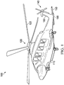
- FIGURE 1 illustrates an example embodiment of a rotorcraft 100.
- Rotorcraft 100 includes a fuselage 110, a rotor system 120, and an empennage 130.
- the fuselage 110 is the main body of the rotorcraft, which may include a cabin for the crew, passengers, and/or cargo, and may also house certain mechanical and electrical components, such as the engine(s), transmission, and flight controls.
- the rotor system 120 is used to generate lift for the rotorcraft using a plurality of rotating rotor blades 122. For example, torque generated by the engine(s) causes the rotor blades 122 to rotate, which in turn generates lift.
- the empennage 130 is the tail assembly of the rotorcraft.
- the empennage 130 includes a tail rotor system 140, which may be used to provide anti-torque and/or directional control.
- the empennage 130 also includes a horizontal stabilizer 150 and a vertical stabilizer 160.
- a stabilizer is an aerodynamic surface or airfoil that produces an aerodynamic lifting force (either positive or negative).
- the stabilizer is a fixed one.
- the primary purpose of a stabilizer is to improve stability about a particular axis (e.g., pitch or yaw stability), although a stabilizer can also provide other secondary aerodynamic benefits.
- a horizontal stabilizer (e.g., horizontal stabilizer 150) is primarily used to provide stability in pitch, or longitudinal stability.
- a horizontal stabilizer may be used to neutralize pitch instability and improve the overall handling qualities of the rotorcraft.
- a horizontal stabilizer may also be used to generate lift for a rotorcraft, for example, to aid in climb or ascent.
- a horizontal stabilizer may also include one or more movable control surfaces, such as an adjustable slat to aid in generating lift.
- the design of a horizontal stabilizer (e.g., airfoil shape, size, position on a rotorcraft, control surfaces) implicates numerous performance considerations and is often an extremely challenging aspect of aircraft design.
- a vertical stabilizer (e.g., vertical stabilizer 160) is primarily used to provide stability in yaw, or directional stability. Although considerable yaw stability and control is often provided by a tail rotor, a vertical stabilizer may be used to supplement the performance of the tail rotor and/or reduce the performance requirements of the tail rotor. Accordingly, designing a vertical stabilizer and a tail rotor often implicates numerous interrelated performance considerations, particularly due to the interaction between their respective airflows. For example, a smaller vertical stabilizer may reduce the adverse effects on tail rotor efficiency, but may adversely impact yaw stability and other design requirements (e.g., sideward flight performance, internal capacity for housing components within the vertical stabilizer). Accordingly, various performance considerations must be carefully balanced when designing a vertical stabilizer.
- This disclosure describes various embodiments of horizontal and vertical stabilizers with designs that balance a variety of performance considerations to provide optimal performance.
- this disclosure describes embodiments of a horizontal stabilizer that is designed to provide strong aerodynamic performance (e.g., pitch stability and/or generating sufficient lift during climb or ascent) without using slats.
- the horizontal stabilizer uses a tailored airfoil design that is cambered and may form a concave slope on the top surface and/or a convex slope on the bottom surface.
- the horizontal stabilizer may be mounted on the aft end of a rotorcraft.
- this horizontal stabilizer design reduces complexity without a performance penalty, thus resulting in a more cost-efficient and reliable solution.
- eliminating the slats similarly eliminates the need to provide anti-icing for the slats, thus providing a further reduction in complexity.
- this disclosure describes embodiments of a vertical stabilizer that is designed to provide strong aerodynamic performance, while also serving as a structural mount for a high tail rotor and as the housing for certain internal components (e.g., the tail rotor driveshaft and other tail rotor components).
- the vertical stabilizer uses a tailored airfoil design that satisfies various design criteria, including strong aerodynamic performance (e.g., yaw stability, anti-torque control, minimal flow separation and drag), dimensions large enough to house various components internally, easy maintenance access (e.g., in the event of a bird strike), and/or reduced manufacturing complexity.
- the vertical stabilizer may have a cambered airfoil shape that provides the requisite yaw stability and anti-torque control while also minimizing flow separation and drag.
- the cambered airfoil shape may enable the vertical stabilizer to provide a portion of the anti-torque required in forward flight (e.g., reducing the anti-torque requirements and power consumption of the tail rotor), and/or may also provide sufficient anti-torque to allow continued flight in the event of a tail rotor failure.
- the cambered airfoil shape may also enable the vertical stabilizer to provide sufficient aerodynamic side-force to offset the tail rotor thrust in forward flight, thus minimizing tail rotor flapping and cyclic loads and maximizing the fatigue life of components.
- the vertical stabilizer may have a blunt trailing edge (rather than a pointed trailing edge) in order to reduce the thickness tapering on the aft end without modifying the desired chord length, thus minimizing flow separation and drag while also reducing manufacturing complexity.
- rotorcraft 100 of FIGURE 1 is merely illustrative of a variety of aircraft that can be used with embodiments described throughout this disclosure.
- Other aircraft implementations can include, for example, fixed wing airplanes, hybrid aircraft, tiltrotor aircraft, unmanned aircraft, gyrocopters, a variety of helicopter configurations, and drones, among other examples.
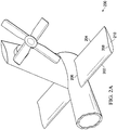
- FIGURES 2A-C illustrate an example embodiment of a horizontal stabilizer 200.
- FIGURE 2A illustrates a three-dimensional view of the horizontal stabilizer
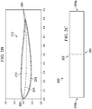
- FIGURE 2B illustrates the airfoil shape of the horizontal stabilizer
- FIGURE 2C illustrates a two-dimensional view of the horizontal stabilizer.
- FIGURE 2A illustrates a three-dimensional view of horizontal stabilizer 200.
- horizontal stabilizer 200 is mounted on the aft end of a rotorcraft.
- horizontal stabilizer 200 may be mounted on the aft spar structure of a vertical stabilizer for simplicity and more effective use of tail volume.
- horizontal stabilizer 200 includes a leading edge 202, trailing edge 204, inboard end 206, and outboard end 208.
- horizontal stabilizer 200 is designed using an aerodynamic airfoil shape 210 that is cambered and forms a concave slope on the top surface and a convex slope on the bottom surface.
- This airfoil shape 210 provides various aerodynamic benefits, including favorable pitch stability and lift coefficients (e.g., increasing the amount of lift produced at a given angle of attack), favorable stall characteristics (e.g., enabling ascent at higher angles of attack without stalling, thus resulting in faster ascent), and a favorable overall lift-to-drag ratio.
- this aerodynamic airfoil shape 210 enables horizontal stabilizer 200 to achieve these aerodynamic benefits even without using slats or other types of adjustable control surfaces.
- this horizontal stabilizer design reduces complexity and weight without a performance penalty, and thus results in a more cost-efficient and reliable design.
- eliminating the slats similarly eliminates the need to provide anti-icing for the slats, thus providing a further reduction in complexity.
- FIGURE 2B illustrates the airfoil shape 210 of horizontal stabilizer 200.
- the illustrated airfoil shape 210 includes a leading edge 202, trailing edge 204, top surface 212, and bottom surface 213.
- the illustrated airfoil shape 210 is also cambered and forms a concave slope on the top surface 212 and a convex slope on the bottom surface 213.
- the mean camber line 211 of airfoil shape 210 is also shown (e.g., the line drawn halfway between the upper and lower surfaces of the airfoil).
- Camber refers to the asymmetry between the top and the bottom surfaces of an airfoil, and is used in airfoil designs to provide various aerodynamic benefits.
- other horizontal stabilizer airfoil designs may have relatively less camber, a flat top or bottom surface, and/or slats for producing additional lift (e.g., the slatted horizontal stabilizer 400 of FIGURE 4 ).
- the illustrated airfoil shape 210 eliminates the need for slats by using an aerodynamic airfoil design that has more camber 211 and forms a concave slope on the top surface 212 and a convex slope on the bottom surface 213.
- the cambered airfoil shape 210 of horizontal stabilizer 200 provides various aerodynamic benefits, including pitch stability, a higher maximum lift coefficient (e.g., increasing the amount of lift produced at a given angle of attack), improved stall characteristics (e.g., ascending at higher angles of attack without stalling and thus resulting in faster ascent), and an improved lift-to-drag ratio.
- Example design parameters for the horizontal stabilizer airfoil shape of FIGURE 2B are provided in TABLE 1.
- TABLE 1 Design parameters for horizontal stabilizer airfoil shape (FIG. 2B) Point X Coordinates Y Coordinates Camber Thickness Upper Surface Lower Surface 1 0 0 0 0 0 2 0.001049 0.0041355 -0.0061515 -0.001008 0.010287 3 0.002508 0.0060715 -0.0098295 -0.001879 0.015901 4 0.004466 0.00782 -0.013356 -0.002768 0.021176 5 0.0056 0.0086285 -0.0150565 -0.003214 0.023685 6 0.006827 0.0093995 -0.0167235 -0.003662 0.026123 7 0.008141 0.010138 -0.018354 -0.004108 0.028492 8 0.009539 0.010846 -0.019948 -0.0045
- FIGURE 2C illustrates a two-dimensional view of an example embodiment of horizontal stabilizer 200.
- horizontal stabilizer 200 has a rectangular shape with four sides that include a leading edge 202, trailing edge 204, right outboard end 210a, and left outboard end 210b.
- horizontal stabilizer 200 may be implemented using the following design parameters: a chord of 23.5 inches, span of 140.98 inches, total area of 23 square feet, maximum thickness of 12% (measured as a percentage of chord length), and angle of incidence in the range of 0.0 degrees to -2.0 degrees to achieve a level cabin during cruise.
- the angle of incidence could be -0.5 degrees, -0.75 degrees, or -1.0 degrees.
- horizontal stabilizer 200 may be positioned on a rotorcraft based on the following waterline (WL), butt line (BL), and fuselage station (FS) locations: BL ranging from 0.0 inches (at the middle of the horizontal stabilizer) to +- 70.49 inches (at the left and right outboard ends of the horizontal stabilizer), and a mean aerodynamic center (MAC) at FS 658.98 inches, BL 0.0 inches, and WL 68.98 inches.
- WL waterline
- BL butt line
- FS fuselage station
- the butt line (BL) refers to the lateral alignment relative to the center of a rotorcraft
- the fuselage station (FS) refers to the alignment along the length of the rotorcraft (e.g., from the nose or another reference point near the forward end of the rotorcraft)
- the waterline (WL) refers to the height from the ground or another reference point below the rotorcraft.
- the described embodiment of horizontal stabilizer 200 can result in a stall margin of approximately 39% in level flight (approximately 61% of the max lift coefficient) and no stall margin in max climb.
- the described embodiment also provides an acceptable pitch attitude during autorotation descent and is designed to stall during steep autorotation (e.g., to avoid producing an upthrust and an undesirable nose-down pitching moment on the fuselage).
- horizontal stabilizer 200 may be implemented using varying design and configuration parameters.
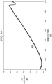
- FIGURES 3A-B illustrate performance graphs for an example embodiment of the horizontal stabilizer of FIGURES 2A-C .
- the graph of FIGURE 3A plots 303 the lift coefficient 301 of the horizontal stabilizer at varying angles of attack 302. In the illustrated graph, as the angle of attack increases, the lift coefficient generally increases and thus more lift is generated, until reaching an angle of attack that causes the horizontal stabilizer to stall.
- the graph of FIGURE 3B plots 313 the drag coefficient 311 of the horizontal stabilizer at varying angles of attack 312.
- the design of the horizontal stabilizer of FIGURES 2A-C results in favorable lift coefficients (e.g., increasing the amount of lift produced at a given angle of attack), favorable stall characteristics (e.g., enabling ascent at higher angles of attack without stalling, thus resulting in faster ascent), and a favorable overall lift-to-drag ratio.
- FIGURE 4 illustrates an example embodiment of a slatted horizontal stabilizer 400.
- the slatted horizontal stabilizer 400 includes a primary airfoil 410 and one or more adjustable slats 411 near the leading edge.
- the adjustable slats 411 may be used to produce certain airflow characteristics at varying angles of attack, for example, to increase the amount of lift produced by the horizontal stabilizer.
- the use of adjustable slats 411 increases the complexity of a horizontal stabilizer, and may also require an aircraft to provide anti-icing capabilities for the adjustable slats.
- the horizontal stabilizer 200 of FIGURES 2A-C is designed to achieve the performance benefits of a slatted design without using slats, thus eliminating the need for both the slats themselves and for any associated anti-icing capabilities, which reduces the complexity, weight, and cost of the stabilizer while improving the overall performance of the aircraft.
- the horizontal stabilizer 200 of FIGURES 2A-C has more camber, a top surface that has a concave slope rather than being flat, and no slats.
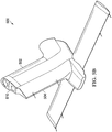
- FIGURES 5A-F illustrate an example embodiment of a vertical stabilizer 500.
- FIGURES 5A-C illustrate three-dimensional views of the vertical stabilizer
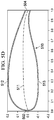
- FIGURES 5D-E illustrate the airfoil shape of the vertical stabilizer
- FIGURE 5F illustrates a two-dimensional view of the vertical stabilizer.
- the design of vertical stabilizer 500 (or a similar variation) can also be used for other fairings, including gear sponsons, sail fairings, spinners, and so forth.
- FIGURES 5A , 5B , and 5C illustrate three-dimensional views of vertical stabilizer 500.
- vertical stabilizer 500 is mounted on the aft end of a rotorcraft, and includes a leading edge 502 and a trailing edge 504.
- Vertical stabilizer 500 is also tapered, and thus gradually decreases in size from bottom to top.
- vertical stabilizer 500 may be a fixed structure with no adjustable control surfaces.
- Vertical stabilizer 500 is designed to provide strong aerodynamic performance, while also serving as a structural mount for a high tail rotor and as the housing for certain internal components (e.g., the tail rotor driveshaft and other tail rotor components, spar structures, hydraulic systems, cooling systems, and so forth).
- the design of vertical stabilizer 500 enables a tail rotor to be mounted near the top of the stabilizer (e.g., high enough to provide head clearance) and also enables the tail rotor to be positioned in the tip-path-plane (TPP) of the main rotor (e.g., to minimize left wheel down roll coupling in hover).
- TPP tip-path-plane
- the design of vertical stabilizer 500 also enables transportability (e.g., in a C5 transport) without disassembling the tail boom or the vertical stabilizer.
- vertical stabilizer 500 uses a tailored airfoil shape 510 that satisfies various design criteria, including strong aerodynamic performance (e.g., yaw or directional stability and control, anti-torque control, minimal flow separation and drag), dimensions large enough to house various components internally and provide a mount for the tail rotor, easy maintenance access (e.g., in the event of a bird strike), and reduced manufacturing complexity.
- strong aerodynamic performance e.g., yaw or directional stability and control, anti-torque control, minimal flow separation and drag
- dimensions large enough to house various components internally and provide a mount for the tail rotor
- easy maintenance access e.g., in the event of a bird strike
- reduced manufacturing complexity e.g., in the event of a bird strike
- FIGURES 5D and 5E illustrate the airfoil shape 510 of vertical stabilizer 500.
- vertical stabilizer 500 is tapered and thus its size and shape varies slightly from top to bottom. Accordingly, the airfoil shape of vertical stabilizer 500 near the top is illustrated in FIGURE 5D , and the airfoil shape of vertical stabilizer 500 near the bottom is illustrated in FIGURE 5E .
- the airfoil shape 510 of vertical stabilizer 500 includes a leading edge 502 and trailing edge 504, and a right side 512 and left side 513.
- the trailing edge 504 is blunt rather than pointed.
- the airfoil shape 510 of vertical stabilizer 500 is also cambered, and the mean camber line 511 for the top and bottom portion is respectively shown in FIGURES 5D and 5E (e.g., the line drawn halfway between the right side 512 and left side 513 of the airfoil).
- the camber of the airfoil shape 510 forms a convex slope on the right side 512, and both a convex slope and a concave slope on the left side 513.
- the airfoil shape 510 of vertical stabilizer 500 provides yaw stability and anti-torque control while also minimizing flow separation and drag.
- the camber of airfoil shape 510 produces a portion of the anti-torque required for stability in forward flight (e.g., approximately half the requisite anti-torque in some cases), thus reducing the anti-torque requirements and power consumption of the tail rotor.
- the resulting anti-torque may also be sufficient to allow continued flight in the event of a tail rotor failure.
- the camber of airfoil shape 510 can also produce sufficient aerodynamic side-force to offset the tail rotor thrust in forward flight, thus minimizing tail rotor flapping and cyclic loads and maximizing the fatigue life of components.
- the trailing edge 504 of the airfoil shape 510 is blunt rather than pointed in order to reduce the thickness tapering on the aft end without modifying the desired chord length, thus minimizing flow separation and drag while also reducing manufacturing complexity (as described further in connection with FIGURE 7 ).
- Example design parameters e.g., coordinates, camber, and thickness
- example design parameters for the vertical stabilizer bottom airfoil shape of FIGURE 5E are provided in TABLE 3.
- TABLE 2 Design parameters for vertical stabilizer top airfoil shape (FIG.
- FIGURE 5F illustrates a two-dimensional view of an example embodiment of vertical stabilizer 500.
- vertical stabilizer 500 has a quadrilateral shape with four sides that include a base 501, tip 503, leading edge 502, and trailing edge 504, and the shape is tapered from the base to the tip.
- vertical stabilizer 500 may be implemented using the following design parameters: a root chord of 43.0 inches, tip chord of 34.5 inches, total area of 23.516 square feet, true span of 87.390 inches, maximum thickness (measured as a percentage of chord length) of 25% at the root and 30% at the tip, leading edge sweep of 25.0 degrees, cant of 15.0 degrees, aspect ratio of 2.255, mean chord of 38.905 inches, and fixed angle of incidence of 2.0 degrees.
- vertical stabilizer 500 may be positioned on a rotorcraft using the following waterline (WL), butt line (BL), and fuselage station (FS) locations: root 501 at WL 67.4; tip 503 at WL 151.812; leading edge and root corner 505a at FS 624.019 and BL 3.172; leading edge and tip corner 505b at FS 664.600 and BL -19.187; trailing edge and root corner 505c at FS 667.019 and BL 3.172; trailing edge and tip corner 505d at FS 699.100 and BL -19.187; and a mean aerodynamic center (MAC) at FS 654.722, BL -7.599, and WL 108.070.
- MAC mean aerodynamic center
- vertical stabilizer 500 may be implemented using varying design and configuration parameters.
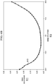
- FIGURES 6A-B i llustrate performance graphs for an example embodiment of the vertical stabilizer of FIGURES 5A-F .
- the graph of FIGURE 6A plots 603 the lift coefficient 601 of the vertical stabilizer at varying angles of attack 602, and the graph of FIGURE 6B plots 613 the drag coefficient 611 of the vertical stabilizer at varying angles of attack 612.
- the design of the vertical stabilizer of FIGURES 5A-F results in favorable aerodynamic qualities, including lift produced laterally for yaw stability, anti-torque control, and offsetting the tail rotor thrust in forward flight, while also minimizing the flow separation and drag.
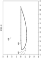
- FIGURE 7 illustrates a comparison of trailing edge shapes for a vertical stabilizer.
- the illustrated example provides a zoomed in view of two airfoil shapes 710a and 710b.
- Airfoil shape 710a has a blunt trailing edge 704a (e.g., similar to the vertical stabilizer of FIGURES 5A-F ), while airfoil shape 710b has a pointed trailing edge 704b.
- the pointed trailing edge 704b of airfoil shape 710b causes early airflow 705 separation because its curvature is too sharp for the airflow 705 to stay attached, and this early airflow separation results in increased drag.
- a vertical stabilizer may be implemented using a blunt trailing edge and reduced thickness tapering on the aft end to minimize flow separation and reduce drag.
- a blunt trailing edge can also reduce manufacturing complexity.
Landscapes
- Engineering & Computer Science (AREA)
- Aviation & Aerospace Engineering (AREA)
- Mechanical Engineering (AREA)
- Lubricants (AREA)
- Turbine Rotor Nozzle Sealing (AREA)
Claims (12)
- Seitenleitwerk (160, 500), umfassend:
eine Tragflächenstruktur (510), die gestaltet ist, an einem Drehflügler (100) in einer vertikalen Ausrichtung montiert zu werden, wobei:die Tragflächenstruktur (510) eine Vorderkante (502) und eine Hinterkante (504) umfasst, wobei die Hinterkante (504) gestaltet ist, eine stumpfe Kante zu bilden;die Tragflächenstruktur (510) weiter ein Wurzelende und ein Spitzenende umfasst, wobei sich die Tragflächenstruktur (510) vom Wurzelende zum Spitzenende hin verjüngt;die Tragflächenstruktur (510) gewölbt ist,die Tragflächenstruktur (510) weiter gestaltet ist, mit einem Heckrotor (140) montiert zu sein, wobei der Heckrotor (140) an der Tragflächenstruktur nahe dem Spitzenende der Tragflächenstruktur (510) montierbar ist, sodass der Heckrotor Rotorblätter stützt, die in einer vertikalen Drehebene außerhalb der Tragflächenstruktur (510) drehen;die Tragflächenstruktur (510) weiter gestaltet ist, eine oder mehrere innere Komponenten aufzunehmen, die dem Flugzeug zugehörig sind; unddie Tragflächenstruktur (510) als eine fixierte Struktur ohne einstellbare Steuerflächen gestaltet ist. - Seitenleitwerk nach Anspruch 1, wobei die eine oder mehreren inneren Komponenten umfassen: ein Heckrotorgetriebe und/oder eine Heckrotorantriebswelle.
- Seitenleitwerk nach einem der vorstehenden Ansprüche, wobei das Seitenleitwerk weiter gestaltet ist, in einem fixierten Anströmwinkel montiert zu sein; und wobei optional oder vorzugsweise der fixierte Anströmwinkel einen Winkel von 2 Grad umfasst.
- Seitenleitwerk nach einem der vorstehenden Ansprüche, wobei eine maximale Dicke des Wurzelendes 25% einer Wurzelsehnenlänge umfasst.
- Seitenleitwerk nach einem der vorstehenden Ansprüche, wobei eine maximale Dicke des Spitzenendes 30% einer Spitzensehnenlänge umfasst.
- Seitenleitwerk nach einem der vorstehenden Ansprüche, wobei die Tragflächenstruktur weiter eine rechte Oberfläche und eine linke Oberfläche umfasst, wobei eine Wölbung der Tragflächenstruktur eine erste konvexe Neigung an der rechten Oberfläche bildet und wobei die Wölbung der Tragflächenstruktur weiter eine zweite konvexe Neigung und eine erste konkave Neigung an der linken Oberfläche bildet.
- Seitenleitwerk nach Anspruch 6, wobei die Wölbung der Tragflächenstruktur gestaltet ist zum:i) Erzeugen eines Auftriebs zur Gierstabilität; und/oderii) Erzeugen eines Auftriebs zum Drehmomentausgleich; und/oderiii) Verringern von Widerstand.
- Seitenleitwerk nach einem der vorstehenden Ansprüche, wobei die stumpfe Kante der Hinterkante (504) die Dickenverjüngung am Heck verringert und als solches gestaltet ist, Widerstand zu verringern.
- Drehflügler, umfassend ein Seitenleitwerk (160, 500) nach Anspruch 1, wobei die Tragflächenstruktur vertikal montiert ist und mit einem Heckrotor montiert ist.
- Drehflügler nach Anspruch 9, wobei die eine oder mehreren inneren Komponenten umfassen: ein Heckrotorgetriebe und/oder eine Heckrotorantriebswelle.
- Drehflügler nach Anspruch 9 oder Anspruch 10, wobei die Tragflächenstruktur (510) weiter eine rechte Oberfläche und eine linke Oberfläche umfasst, wobei eine Wölbung der Tragflächenstruktur eine erste konvexe Neigung an der rechten Oberfläche bildet und wobei die Wölbung der Tragflächenstruktur weiter eine zweite konvexe Neigung und eine erste konkave Neigung an der linken Oberfläche bildet.
- Drehflügler nach einem der Ansprüche 9 bis 11, wobei die stumpfe Kante der Hinterkante (504) die Dickenverjüngung am Heck verringert und als solches gestaltet ist, Widerstand zu verringern.
Applications Claiming Priority (1)
| Application Number | Priority Date | Filing Date | Title |
|---|---|---|---|
| US15/593,304 US10611460B2 (en) | 2017-05-11 | 2017-05-11 | Aircraft vertical stabilizer design |
Publications (2)
| Publication Number | Publication Date |
|---|---|
| EP3401212A1 EP3401212A1 (de) | 2018-11-14 |
| EP3401212B1 true EP3401212B1 (de) | 2020-08-05 |
Family
ID=59895194
Family Applications (1)
| Application Number | Title | Priority Date | Filing Date |
|---|---|---|---|
| EP17191479.9A Active EP3401212B1 (de) | 2017-05-11 | 2017-09-15 | Flugzeugseitenleitwerkdesign |
Country Status (2)
| Country | Link |
|---|---|
| US (1) | US10611460B2 (de) |
| EP (1) | EP3401212B1 (de) |
Families Citing this family (4)
| Publication number | Priority date | Publication date | Assignee | Title |
|---|---|---|---|---|
| US10611460B2 (en) | 2017-05-11 | 2020-04-07 | Bell Helicopter Textron Inc. | Aircraft vertical stabilizer design |
| US10518865B2 (en) | 2017-05-11 | 2019-12-31 | Bell Helicopter Textron Inc. | Aircraft horizontal stabilizer design |
| EP3882128B1 (de) * | 2020-03-19 | 2022-08-31 | LEONARDO S.p.A. | Hubschrauber, hubschrauber-kit und zugehöriges rekonfigurationsverfahren |
| JP2024106285A (ja) | 2023-01-26 | 2024-08-07 | 株式会社Subaru | ヘリコプタ、ヘリコプタの垂直尾翼、ヘリコプタの垂直尾翼の改修方法及びヘリコプタのテールロータによるアンチトルクの向上方法 |
Citations (1)
| Publication number | Priority date | Publication date | Assignee | Title |
|---|---|---|---|---|
| US20090189023A1 (en) * | 2008-01-28 | 2009-07-30 | Eurocopter Deutschland Gmbh | Aerodynamic high-performance profile for aircraft |
Family Cites Families (16)
| Publication number | Priority date | Publication date | Assignee | Title |
|---|---|---|---|---|
| US1506817A (en) * | 1921-12-23 | 1924-09-02 | Dornier Metallbauten Gmbh | Bearing plane for aircraft |
| FR1511006A (fr) * | 1966-12-13 | 1968-01-26 | Sud Aviation | Dispositif directionnel et propulsif pour hélicoptère |
| US3966145A (en) * | 1975-02-28 | 1976-06-29 | The Boeing Company | Structure for cooling helicopter tail rotor gearbox |
| FR2600036B1 (fr) * | 1986-06-16 | 1988-09-16 | Aerospatiale | Dispositif directionnel et stabilisateur a rotor anti-couple carene et incline et a empennage en " v " dissymetrique, et helicoptere equipe d'un tel dispositif. |
| US5058837A (en) | 1989-04-07 | 1991-10-22 | Wheeler Gary O | Low drag vortex generators |
| US5108044A (en) | 1991-04-11 | 1992-04-28 | United Technologies Corporation | Shroud-fin integration shelf for a helicopter empennage structure |
| FR2689854B1 (fr) | 1992-04-14 | 1994-07-01 | Eurocopter France | Helicoptere monorotor a systeme anticouple mixte et procede pour contrecarrer le couple induit par ce monorotor. |
| US5252381A (en) * | 1992-06-18 | 1993-10-12 | Adler Alan John | Airfoil with thick trailing edge |
| DE102006032003B4 (de) | 2006-07-11 | 2015-10-22 | Airbus Operations Gmbh | Trimmbares Höhenleitwerk |
| US8840058B2 (en) * | 2010-09-20 | 2014-09-23 | Textron Innovations Inc. | Airfoil shaped tail boom |
| FR2990926B1 (fr) | 2012-05-22 | 2014-11-28 | Eurocopter France | Moyen de stabilisation en tangage et aeronef a voilure tournante muni d'un tel moyen |
| CA2918779C (en) | 2013-07-22 | 2021-03-16 | Learjet Inc. | Tailplane with positive camber |
| EP2933187B1 (de) * | 2014-04-15 | 2017-01-11 | AIRBUS HELICOPTERS DEUTSCHLAND GmbH | Drehflügelflugzeug mit einem mehrholmigen Heckausleger |
| FR3026386B1 (fr) | 2014-09-30 | 2016-10-21 | Airbus Helicopters | Giravion muni d'un dispositif stabilisateur |
| US10518865B2 (en) | 2017-05-11 | 2019-12-31 | Bell Helicopter Textron Inc. | Aircraft horizontal stabilizer design |
| US10611460B2 (en) | 2017-05-11 | 2020-04-07 | Bell Helicopter Textron Inc. | Aircraft vertical stabilizer design |
-
2017
- 2017-05-11 US US15/593,304 patent/US10611460B2/en active Active
- 2017-09-15 EP EP17191479.9A patent/EP3401212B1/de active Active
Patent Citations (1)
| Publication number | Priority date | Publication date | Assignee | Title |
|---|---|---|---|---|
| US20090189023A1 (en) * | 2008-01-28 | 2009-07-30 | Eurocopter Deutschland Gmbh | Aerodynamic high-performance profile for aircraft |
Also Published As
| Publication number | Publication date |
|---|---|
| EP3401212A1 (de) | 2018-11-14 |
| US10611460B2 (en) | 2020-04-07 |
| US20180327079A1 (en) | 2018-11-15 |
Similar Documents
| Publication | Publication Date | Title |
|---|---|---|
| US11634218B2 (en) | Redundant drive train for pylon mounted rotors | |
| CN112141328B (zh) | 飞机 | |
| EP3401211B1 (de) | Konstruktion horizontaler flugzeugstabilisatoren | |
| US11180248B2 (en) | Fixed wing aircraft with trailing rotors | |
| EP3296202B1 (de) | Flügelerweiterungswinglets für ein kipprotorflugzeug | |
| JP6949869B2 (ja) | テイルシッター航空機用回転翼アセンブリ | |
| US11673643B2 (en) | Low stall or minimum control speed aircraft | |
| US20220363376A1 (en) | Free Wing Multirotor Transitional S/VTOL Aircraft | |
| EP3670341A1 (de) | Senkrecht startendes und landendes (vtol) flugzeug | |
| CN114026022A (zh) | 具有后旋翼和t型尾翼的固定翼飞机 | |
| EP3483059B1 (de) | Doppeldecker-kipprotorflugzeug | |
| US20200290718A1 (en) | Unmanned aerial vehicle | |
| JP2017528355A (ja) | 高性能垂直離着陸航空機 | |
| EP3401212B1 (de) | Flugzeugseitenleitwerkdesign | |
| CN111348183B (zh) | 飞行器 | |
| CN110431076B (zh) | 无尾飞机 | |
| CN214875553U (zh) | 一种分布式推进的纵列式高速无人直升机 | |
| US20250042542A1 (en) | Fixed-Wing Aircraft | |
| CN218617171U (zh) | 一种多旋翼飞行器 | |
| CN223721143U (zh) | 一种叠层倾转旋翼结构的飞行器 | |
| US10654556B2 (en) | VTOL aircraft with wings | |
| US12486026B1 (en) | Aerodynamic rotor blade strake | |
| CN120096804A (zh) | 一种叠层倾转旋翼结构的飞行器及控制方法 | |
| WO2025177317A2 (en) | Aerial vehicle with forked wing ends carrying thrust producing units | |
| Basri et al. | The Effect of Elevons Deflection to Aerodynamic Coefficients of A Tail-less Blended Wing-Body Planform |
Legal Events
| Date | Code | Title | Description |
|---|---|---|---|
| STAA | Information on the status of an ep patent application or granted ep patent |
Free format text: STATUS: EXAMINATION IS IN PROGRESS |
|
| PUAI | Public reference made under article 153(3) epc to a published international application that has entered the european phase |
Free format text: ORIGINAL CODE: 0009012 |
|
| 17P | Request for examination filed |
Effective date: 20170915 |
|
| AK | Designated contracting states |
Kind code of ref document: A1 Designated state(s): AL AT BE BG CH CY CZ DE DK EE ES FI FR GB GR HR HU IE IS IT LI LT LU LV MC MK MT NL NO PL PT RO RS SE SI SK SM TR |
|
| AX | Request for extension of the european patent |
Extension state: BA ME |
|
| GRAP | Despatch of communication of intention to grant a patent |
Free format text: ORIGINAL CODE: EPIDOSNIGR1 |
|
| STAA | Information on the status of an ep patent application or granted ep patent |
Free format text: STATUS: GRANT OF PATENT IS INTENDED |
|
| RIC1 | Information provided on ipc code assigned before grant |
Ipc: B64C 5/06 20060101AFI20200414BHEP Ipc: B64C 27/82 20060101ALN20200414BHEP |
|
| INTG | Intention to grant announced |
Effective date: 20200504 |
|
| RIC1 | Information provided on ipc code assigned before grant |
Ipc: B64C 27/82 20060101ALN20200420BHEP Ipc: B64C 5/06 20060101AFI20200420BHEP |
|
| GRAS | Grant fee paid |
Free format text: ORIGINAL CODE: EPIDOSNIGR3 |
|
| GRAA | (expected) grant |
Free format text: ORIGINAL CODE: 0009210 |
|
| STAA | Information on the status of an ep patent application or granted ep patent |
Free format text: STATUS: THE PATENT HAS BEEN GRANTED |
|
| AK | Designated contracting states |
Kind code of ref document: B1 Designated state(s): AL AT BE BG CH CY CZ DE DK EE ES FI FR GB GR HR HU IE IS IT LI LT LU LV MC MK MT NL NO PL PT RO RS SE SI SK SM TR |
|
| REG | Reference to a national code |
Ref country code: GB Ref legal event code: FG4D |
|
| REG | Reference to a national code |
Ref country code: CH Ref legal event code: EP |
|
| REG | Reference to a national code |
Ref country code: AT Ref legal event code: REF Ref document number: 1298377 Country of ref document: AT Kind code of ref document: T Effective date: 20200815 |
|
| REG | Reference to a national code |
Ref country code: DE Ref legal event code: R096 Ref document number: 602017020920 Country of ref document: DE |
|
| REG | Reference to a national code |
Ref country code: IE Ref legal event code: FG4D |
|
| REG | Reference to a national code |
Ref country code: LT Ref legal event code: MG4D |
|
| REG | Reference to a national code |
Ref country code: NL Ref legal event code: MP Effective date: 20200805 |
|
| REG | Reference to a national code |
Ref country code: AT Ref legal event code: MK05 Ref document number: 1298377 Country of ref document: AT Kind code of ref document: T Effective date: 20200805 |
|
| PG25 | Lapsed in a contracting state [announced via postgrant information from national office to epo] |
Ref country code: FI Free format text: LAPSE BECAUSE OF FAILURE TO SUBMIT A TRANSLATION OF THE DESCRIPTION OR TO PAY THE FEE WITHIN THE PRESCRIBED TIME-LIMIT Effective date: 20200805 Ref country code: NO Free format text: LAPSE BECAUSE OF FAILURE TO SUBMIT A TRANSLATION OF THE DESCRIPTION OR TO PAY THE FEE WITHIN THE PRESCRIBED TIME-LIMIT Effective date: 20201105 Ref country code: GR Free format text: LAPSE BECAUSE OF FAILURE TO SUBMIT A TRANSLATION OF THE DESCRIPTION OR TO PAY THE FEE WITHIN THE PRESCRIBED TIME-LIMIT Effective date: 20201106 Ref country code: BG Free format text: LAPSE BECAUSE OF FAILURE TO SUBMIT A TRANSLATION OF THE DESCRIPTION OR TO PAY THE FEE WITHIN THE PRESCRIBED TIME-LIMIT Effective date: 20201105 Ref country code: SE Free format text: LAPSE BECAUSE OF FAILURE TO SUBMIT A TRANSLATION OF THE DESCRIPTION OR TO PAY THE FEE WITHIN THE PRESCRIBED TIME-LIMIT Effective date: 20200805 Ref country code: PT Free format text: LAPSE BECAUSE OF FAILURE TO SUBMIT A TRANSLATION OF THE DESCRIPTION OR TO PAY THE FEE WITHIN THE PRESCRIBED TIME-LIMIT Effective date: 20201207 Ref country code: AT Free format text: LAPSE BECAUSE OF FAILURE TO SUBMIT A TRANSLATION OF THE DESCRIPTION OR TO PAY THE FEE WITHIN THE PRESCRIBED TIME-LIMIT Effective date: 20200805 Ref country code: HR Free format text: LAPSE BECAUSE OF FAILURE TO SUBMIT A TRANSLATION OF THE DESCRIPTION OR TO PAY THE FEE WITHIN THE PRESCRIBED TIME-LIMIT Effective date: 20200805 Ref country code: LT Free format text: LAPSE BECAUSE OF FAILURE TO SUBMIT A TRANSLATION OF THE DESCRIPTION OR TO PAY THE FEE WITHIN THE PRESCRIBED TIME-LIMIT Effective date: 20200805 Ref country code: ES Free format text: LAPSE BECAUSE OF FAILURE TO SUBMIT A TRANSLATION OF THE DESCRIPTION OR TO PAY THE FEE WITHIN THE PRESCRIBED TIME-LIMIT Effective date: 20200805 |
|
| PG25 | Lapsed in a contracting state [announced via postgrant information from national office to epo] |
Ref country code: PL Free format text: LAPSE BECAUSE OF FAILURE TO SUBMIT A TRANSLATION OF THE DESCRIPTION OR TO PAY THE FEE WITHIN THE PRESCRIBED TIME-LIMIT Effective date: 20200805 Ref country code: NL Free format text: LAPSE BECAUSE OF FAILURE TO SUBMIT A TRANSLATION OF THE DESCRIPTION OR TO PAY THE FEE WITHIN THE PRESCRIBED TIME-LIMIT Effective date: 20200805 Ref country code: LV Free format text: LAPSE BECAUSE OF FAILURE TO SUBMIT A TRANSLATION OF THE DESCRIPTION OR TO PAY THE FEE WITHIN THE PRESCRIBED TIME-LIMIT Effective date: 20200805 Ref country code: RS Free format text: LAPSE BECAUSE OF FAILURE TO SUBMIT A TRANSLATION OF THE DESCRIPTION OR TO PAY THE FEE WITHIN THE PRESCRIBED TIME-LIMIT Effective date: 20200805 Ref country code: IS Free format text: LAPSE BECAUSE OF FAILURE TO SUBMIT A TRANSLATION OF THE DESCRIPTION OR TO PAY THE FEE WITHIN THE PRESCRIBED TIME-LIMIT Effective date: 20201205 |
|
| PG25 | Lapsed in a contracting state [announced via postgrant information from national office to epo] |
Ref country code: RO Free format text: LAPSE BECAUSE OF FAILURE TO SUBMIT A TRANSLATION OF THE DESCRIPTION OR TO PAY THE FEE WITHIN THE PRESCRIBED TIME-LIMIT Effective date: 20200805 Ref country code: DK Free format text: LAPSE BECAUSE OF FAILURE TO SUBMIT A TRANSLATION OF THE DESCRIPTION OR TO PAY THE FEE WITHIN THE PRESCRIBED TIME-LIMIT Effective date: 20200805 Ref country code: CZ Free format text: LAPSE BECAUSE OF FAILURE TO SUBMIT A TRANSLATION OF THE DESCRIPTION OR TO PAY THE FEE WITHIN THE PRESCRIBED TIME-LIMIT Effective date: 20200805 Ref country code: EE Free format text: LAPSE BECAUSE OF FAILURE TO SUBMIT A TRANSLATION OF THE DESCRIPTION OR TO PAY THE FEE WITHIN THE PRESCRIBED TIME-LIMIT Effective date: 20200805 Ref country code: SM Free format text: LAPSE BECAUSE OF FAILURE TO SUBMIT A TRANSLATION OF THE DESCRIPTION OR TO PAY THE FEE WITHIN THE PRESCRIBED TIME-LIMIT Effective date: 20200805 |
|
| REG | Reference to a national code |
Ref country code: CH Ref legal event code: PL |
|
| REG | Reference to a national code |
Ref country code: DE Ref legal event code: R097 Ref document number: 602017020920 Country of ref document: DE |
|
| PG25 | Lapsed in a contracting state [announced via postgrant information from national office to epo] |
Ref country code: AL Free format text: LAPSE BECAUSE OF FAILURE TO SUBMIT A TRANSLATION OF THE DESCRIPTION OR TO PAY THE FEE WITHIN THE PRESCRIBED TIME-LIMIT Effective date: 20200805 Ref country code: MC Free format text: LAPSE BECAUSE OF FAILURE TO SUBMIT A TRANSLATION OF THE DESCRIPTION OR TO PAY THE FEE WITHIN THE PRESCRIBED TIME-LIMIT Effective date: 20200805 |
|
| PLBE | No opposition filed within time limit |
Free format text: ORIGINAL CODE: 0009261 |
|
| STAA | Information on the status of an ep patent application or granted ep patent |
Free format text: STATUS: NO OPPOSITION FILED WITHIN TIME LIMIT |
|
| REG | Reference to a national code |
Ref country code: BE Ref legal event code: MM Effective date: 20200930 |
|
| PG25 | Lapsed in a contracting state [announced via postgrant information from national office to epo] |
Ref country code: LU Free format text: LAPSE BECAUSE OF NON-PAYMENT OF DUE FEES Effective date: 20200915 Ref country code: SK Free format text: LAPSE BECAUSE OF FAILURE TO SUBMIT A TRANSLATION OF THE DESCRIPTION OR TO PAY THE FEE WITHIN THE PRESCRIBED TIME-LIMIT Effective date: 20200805 |
|
| 26N | No opposition filed |
Effective date: 20210507 |
|
| PG25 | Lapsed in a contracting state [announced via postgrant information from national office to epo] |
Ref country code: CH Free format text: LAPSE BECAUSE OF NON-PAYMENT OF DUE FEES Effective date: 20200930 Ref country code: BE Free format text: LAPSE BECAUSE OF NON-PAYMENT OF DUE FEES Effective date: 20200930 Ref country code: SI Free format text: LAPSE BECAUSE OF FAILURE TO SUBMIT A TRANSLATION OF THE DESCRIPTION OR TO PAY THE FEE WITHIN THE PRESCRIBED TIME-LIMIT Effective date: 20200805 Ref country code: IE Free format text: LAPSE BECAUSE OF NON-PAYMENT OF DUE FEES Effective date: 20200915 Ref country code: LI Free format text: LAPSE BECAUSE OF NON-PAYMENT OF DUE FEES Effective date: 20200930 |
|
| PG25 | Lapsed in a contracting state [announced via postgrant information from national office to epo] |
Ref country code: TR Free format text: LAPSE BECAUSE OF FAILURE TO SUBMIT A TRANSLATION OF THE DESCRIPTION OR TO PAY THE FEE WITHIN THE PRESCRIBED TIME-LIMIT Effective date: 20200805 Ref country code: MT Free format text: LAPSE BECAUSE OF FAILURE TO SUBMIT A TRANSLATION OF THE DESCRIPTION OR TO PAY THE FEE WITHIN THE PRESCRIBED TIME-LIMIT Effective date: 20200805 Ref country code: CY Free format text: LAPSE BECAUSE OF FAILURE TO SUBMIT A TRANSLATION OF THE DESCRIPTION OR TO PAY THE FEE WITHIN THE PRESCRIBED TIME-LIMIT Effective date: 20200805 |
|
| PG25 | Lapsed in a contracting state [announced via postgrant information from national office to epo] |
Ref country code: MK Free format text: LAPSE BECAUSE OF FAILURE TO SUBMIT A TRANSLATION OF THE DESCRIPTION OR TO PAY THE FEE WITHIN THE PRESCRIBED TIME-LIMIT Effective date: 20200805 |
|
| P01 | Opt-out of the competence of the unified patent court (upc) registered |
Effective date: 20230602 |
|
| PGFP | Annual fee paid to national office [announced via postgrant information from national office to epo] |
Ref country code: DE Payment date: 20250929 Year of fee payment: 9 |
|
| PGFP | Annual fee paid to national office [announced via postgrant information from national office to epo] |
Ref country code: IT Payment date: 20250919 Year of fee payment: 9 |
|
| PGFP | Annual fee paid to national office [announced via postgrant information from national office to epo] |
Ref country code: GB Payment date: 20250929 Year of fee payment: 9 |
|
| PGFP | Annual fee paid to national office [announced via postgrant information from national office to epo] |
Ref country code: FR Payment date: 20250925 Year of fee payment: 9 |