EP3401226B1 - Vorrichtung und verfahren zum abdichten oder zubinden von produkten und verwendung der vorrichtung - Google Patents
Vorrichtung und verfahren zum abdichten oder zubinden von produkten und verwendung der vorrichtung Download PDFInfo
- Publication number
- EP3401226B1 EP3401226B1 EP18171563.2A EP18171563A EP3401226B1 EP 3401226 B1 EP3401226 B1 EP 3401226B1 EP 18171563 A EP18171563 A EP 18171563A EP 3401226 B1 EP3401226 B1 EP 3401226B1
- Authority
- EP
- European Patent Office
- Prior art keywords
- star wheel
- knife
- cell
- tape
- products
- Prior art date
- Legal status (The legal status is an assumption and is not a legal conclusion. Google has not performed a legal analysis and makes no representation as to the accuracy of the status listed.)
- Active
Links
Images






Classifications
-
- B—PERFORMING OPERATIONS; TRANSPORTING
- B65—CONVEYING; PACKING; STORING; HANDLING THIN OR FILAMENTARY MATERIAL
- B65B—MACHINES, APPARATUS OR DEVICES FOR, OR METHODS OF, PACKAGING ARTICLES OR MATERIALS; UNPACKING
- B65B25/00—Packaging other articles presenting special problems
- B65B25/02—Packaging agricultural or horticultural products
- B65B25/023—Packaging flower bouquets
-
- B—PERFORMING OPERATIONS; TRANSPORTING
- B65—CONVEYING; PACKING; STORING; HANDLING THIN OR FILAMENTARY MATERIAL
- B65B—MACHINES, APPARATUS OR DEVICES FOR, OR METHODS OF, PACKAGING ARTICLES OR MATERIALS; UNPACKING
- B65B13/00—Bundling articles
- B65B13/02—Applying and securing binding material around articles or groups of articles, e.g. using strings, wires, strips, bands or tapes
- B65B13/16—Applying and securing binding material around articles or groups of articles, e.g. using strings, wires, strips, bands or tapes with means for severing the binding material from supply and then applying it around the articles
-
- B—PERFORMING OPERATIONS; TRANSPORTING
- B65—CONVEYING; PACKING; STORING; HANDLING THIN OR FILAMENTARY MATERIAL
- B65B—MACHINES, APPARATUS OR DEVICES FOR, OR METHODS OF, PACKAGING ARTICLES OR MATERIALS; UNPACKING
- B65B13/00—Bundling articles
- B65B13/18—Details of, or auxiliary devices used in, bundling machines or bundling tools
- B65B13/24—Securing ends of binding material
- B65B13/34—Securing ends of binding material by applying separate securing members, e.g. deformable clips
-
- B—PERFORMING OPERATIONS; TRANSPORTING
- B65—CONVEYING; PACKING; STORING; HANDLING THIN OR FILAMENTARY MATERIAL
- B65B—MACHINES, APPARATUS OR DEVICES FOR, OR METHODS OF, PACKAGING ARTICLES OR MATERIALS; UNPACKING
- B65B27/00—Bundling particular articles presenting special problems using string, wire, or narrow tape or band; Baling fibrous material, e.g. peat, not otherwise provided for
- B65B27/10—Bundling rods, sticks, or like elongated objects
- B65B27/105—Bundling rods, sticks, or like elongated objects by means of adhesive tape
-
- B—PERFORMING OPERATIONS; TRANSPORTING
- B65—CONVEYING; PACKING; STORING; HANDLING THIN OR FILAMENTARY MATERIAL
- B65B—MACHINES, APPARATUS OR DEVICES FOR, OR METHODS OF, PACKAGING ARTICLES OR MATERIALS; UNPACKING
- B65B51/00—Devices for, or methods of, sealing or securing package folds or closures; Devices for gathering or twisting wrappers, or necks of bags
- B65B51/04—Applying separate sealing or securing members, e.g. clips
- B65B51/06—Applying adhesive tape
- B65B51/065—Applying adhesive tape to the necks of bags
-
- B—PERFORMING OPERATIONS; TRANSPORTING
- B65—CONVEYING; PACKING; STORING; HANDLING THIN OR FILAMENTARY MATERIAL
- B65B—MACHINES, APPARATUS OR DEVICES FOR, OR METHODS OF, PACKAGING ARTICLES OR MATERIALS; UNPACKING
- B65B61/00—Auxiliary devices, not otherwise provided for, for operating on sheets, blanks, webs, binding material, containers or packages
- B65B61/20—Auxiliary devices, not otherwise provided for, for operating on sheets, blanks, webs, binding material, containers or packages for adding cards, coupons or other inserts to package contents
-
- B—PERFORMING OPERATIONS; TRANSPORTING
- B29—WORKING OF PLASTICS; WORKING OF SUBSTANCES IN A PLASTIC STATE IN GENERAL
- B29C—SHAPING OR JOINING OF PLASTICS; SHAPING OF MATERIAL IN A PLASTIC STATE, NOT OTHERWISE PROVIDED FOR; AFTER-TREATMENT OF THE SHAPED PRODUCTS, e.g. REPAIRING
- B29C66/00—General aspects of processes or apparatus for joining preformed parts
- B29C66/90—Measuring or controlling the joining process
- B29C66/95—Measuring or controlling the joining process by measuring or controlling specific variables not covered by groups B29C66/91 - B29C66/94
-
- B—PERFORMING OPERATIONS; TRANSPORTING
- B32—LAYERED PRODUCTS
- B32B—LAYERED PRODUCTS, i.e. PRODUCTS BUILT-UP OF STRATA OF FLAT OR NON-FLAT, e.g. CELLULAR OR HONEYCOMB, FORM
- B32B38/00—Ancillary operations in connection with laminating processes
- B32B38/0004—Cutting, tearing or severing, e.g. bursting; Cutter details
-
- B—PERFORMING OPERATIONS; TRANSPORTING
- B65—CONVEYING; PACKING; STORING; HANDLING THIN OR FILAMENTARY MATERIAL
- B65B—MACHINES, APPARATUS OR DEVICES FOR, OR METHODS OF, PACKAGING ARTICLES OR MATERIALS; UNPACKING
- B65B67/00—Apparatus or devices facilitating manual packaging operations; Sack holders
- B65B67/02—Packaging of articles or materials in containers
- B65B67/06—Manually-operable devices for closing bag necks, by applying and securing lengths of string, wire or tape
-
- Y—GENERAL TAGGING OF NEW TECHNOLOGICAL DEVELOPMENTS; GENERAL TAGGING OF CROSS-SECTIONAL TECHNOLOGIES SPANNING OVER SEVERAL SECTIONS OF THE IPC; TECHNICAL SUBJECTS COVERED BY FORMER USPC CROSS-REFERENCE ART COLLECTIONS [XRACs] AND DIGESTS
- Y10—TECHNICAL SUBJECTS COVERED BY FORMER USPC
- Y10T—TECHNICAL SUBJECTS COVERED BY FORMER US CLASSIFICATION
- Y10T156/00—Adhesive bonding and miscellaneous chemical manufacture
- Y10T156/12—Surface bonding means and/or assembly means with cutting, punching, piercing, severing or tearing
- Y10T156/1317—Means feeding plural workpieces to be joined
- Y10T156/1322—Severing before bonding or assembling of parts
- Y10T156/1339—Delivering cut part in sequence to serially conveyed articles
-
- Y—GENERAL TAGGING OF NEW TECHNOLOGICAL DEVELOPMENTS; GENERAL TAGGING OF CROSS-SECTIONAL TECHNOLOGIES SPANNING OVER SEVERAL SECTIONS OF THE IPC; TECHNICAL SUBJECTS COVERED BY FORMER USPC CROSS-REFERENCE ART COLLECTIONS [XRACs] AND DIGESTS
- Y10—TECHNICAL SUBJECTS COVERED BY FORMER USPC
- Y10T—TECHNICAL SUBJECTS COVERED BY FORMER US CLASSIFICATION
- Y10T156/00—Adhesive bonding and miscellaneous chemical manufacture
- Y10T156/12—Surface bonding means and/or assembly means with cutting, punching, piercing, severing or tearing
- Y10T156/1317—Means feeding plural workpieces to be joined
- Y10T156/1343—Cutting indefinite length web after assembly with discrete article
Definitions
- the invention relates to an apparatus, method for sealing or tying products and to the use of an apparatus for binding products.
- the invention more specifically relates to an apparatus and method for wrapping at least an adhesive strip of tape around at least part of a bundle of products for tying them together.
- a sealer having a wheel comprising a series of slots defined in the periphery thereof, regularly spaced relative to each other along said periphery. Between each set of two adjacent slots a knife is housed in the wheel, having a cutting edge extending slightly from said periphery. Tape fed over the periphery can be cut by such cutting edge when the wheel is turned during feed through of a bag to be closed and sealed.
- a sealer having a star wheel having six identical slots provided evenly distributed around the periphery of the star wheel. Products can be hand fed through a slot in the housing of this sealer for rotating the wheel and sealing the bag.
- EP2635495 discloses an apparatus for binding, especially taping products or bundles of products, comprising a star wheel with a series of first cells and a series of second cells, first and second cells being intermittingly provided around the periphery of the star wheel.
- a knife carrier is provided alongside the periphery of the star wheel, allowing a knife to be moved into and out of a second cell for cutting the tape.
- a sealer with a star wheel wherein the star wheel has four first slots into which the neck of a bag to be sealed can be fed, and in the middle between two adjacent first slots a second slot is provided for allowing a knife to cut tape fed over the periphery of the wheel.
- WO 2015/174845 A1 an apparatus for sealing or tying products with a star wheel is disclosed, wherein the star wheel has first cells into which the to be sealed products can be fed, and the housing comprises a movable knife that can move into second cells of the star wheel.
- a bag-tying machine with a star wheel wherein the star wheel has four cell into which the neck of a bag can be inserted, and adjacent to the cells are four knifes that can engage an anvil roller in order to cut the tape.
- a device comprising a wheel with a single cell into which and end of a bag can be fed is disclosed for applying a loop of self-adhesive tape around the end of a bag, the housing of the device is provided with a movable anvil that can engage a knife attached to the housing.
- a sealer is disclosed with a star wheel, wherein the star wheel has slots into which a bundle of products can be inserted, and attached to the sides of the star wheel are provided movable knifes for cutting tape wrapped around tape by engaging anvils that are provided in the star wheel.
- An aim of the present invention is to provide an alternative to these known apparatus and methods. Another aim of the present invention is to provide a method and apparatus for sealing or tying products into bundles. A still further aim is to provide a method and apparatus for tying fresh produce, flowers or the like natural products. An aim of the present disclosure is to ensure proper cutting of tape extending along part of the periphery of the star wheel.
- a container can be described to be tied by the tape with the product or products.
- Such container can for example be, but is not limited to, a sachet, bag, flask, box, bottle or any container suitable for holding content.
- other items could be tied to a product or bundle of products in the same or similar manner. Such items are, for the purpose of this description, also to be understood as encompassed by the description.
- apparatus which may be hand-operated, that is wherein products to be tied or sealed are fed through the apparatus manually, and apparatus which may be mechanically driven, for example motor driven.
- Mechanical means can be provided to feed the products through the apparatus, or at least assist a user in feeding the products through the apparatus, such as transport bands, chains and other transport means.
- Star wheel should be understood as at least including any element, rotational around a real or virtual axis, provided with cells along the periphery forming positions for receiving products or parts thereof to be tied or sealed and/or receiving at least part of a knife or other cutting or slicing tool or element.
- first cell can be understood as meaning a first cell following the said first cell seen in a direction of rotation of the star wheel, which can be used for tying or sealing products.
- knives and anvils will be described which are movable, relative to a star wheel.
- a knife movable should be understood as movable relative to tape extending along a relevant part of the star wheel, in order to cut the tape or tapes.
- Such movement may be in any direction and can especially include a substantial radial direction or a substantially axial direction.
- a substantial radial direction should be understood at least as a direction extending from an axis of the star wheel outward, substantially perpendicular to a tangent to the periphery of the star wheel. Such substantially radial direction may extend as a normal to the axis of the star wheel.
- a substantial axial direction should be understood at least as a direction extending substantially parallel to an axis of rotation of the star wheel.
- a knife can also move in a combined axial and radial direction.
- Fig. 1 and 2 show a first exemplary embodiment of an apparatus.
- the apparatus 1 comprises a housing 2, at least a first tape dispenser 3 and a star wheel 4.
- a slot 5 is defined by or through the housing 2.
- the star wheel 4 extends at least partly in said slot 5.
- the housing 2 comprises a front panel 6 and back panel 7 and rests on legs 8 for providing stability and the possibility of moving the apparatus 1 to an appropriate position.
- the apparatus can thus be mobile.
- the slot 5 extends from an inlet opening 9 to an outlet opening 10.
- the outlet opening 10 can be provided between the inlet opening 9 and the legs 8.
- the outlet opening 10 opens into a hole 11 extending through the housing 2, opening to both the front 12 and back 13 thereof.
- the slot 5 is formed by cut outs in the front panel 6 and back panel 7.
- the star wheel 4 can be mounted on an axis 15, extending substantially perpendicular to the front and back 12, 13 of the housing 2, such that it can be rotated around said axis 15 within the housing 2.
- the inlet opening 9 and outlet opening 10 can be positioned such that a straight line L drawn between a mid 16 of the inlet opening 9 and a mid 17 of the outlet opening 10 extends past the axis 15 at a distance D1 there from.
- the slot 5 is curved between the inlet opening 9 and outlet opening 10 such that it passes the axis 15, a mid 18 thereof being at a distance D2 from the axis 15.
- the distance D2 can in an embodiment be larger than the distance D1. In other embodiments it can be smaller or the same.
- the star wheel 4 comprises a series of first cells 19 and a series of second cells 20.
- the position of each cell 19, 20 is for the sake of this description defined by a line J extending through the axis 15 and a mid M of a relevant cell 19, 20 at the periphery 21.
- the first cells 19 and second cells 20 can be intermittently disposed in the star wheel 4. This has to be understood as including but not necessarily limited to an arrangement of the cells 19, 20 around the periphery 21 of the star wheel 4 such that between two adjacent first cells 19 seen around the periphery 21 a second cell 20 is provided.
- Each first cell 19 is open to the periphery 21 of the star wheel 4 and two opposite sides 22, 23 thereof. In the embodiments shown there is the same number of first cells 19 as there are second cells 20.
- first cells 19 there can be three first cells 19 and three second cells 20.
- first cells 19 can be distributed around the periphery 21 evenly, as can the second cells 20.
- first cells 19 this means that an angle ⁇ included between two lines J through adjacent first cells 19 will be approximately 120 degrees.
- second cells 20 the angle ⁇ included between two lines J through adjacent second cells 20 will be approximately 120 degrees.
- the angles ⁇ , ⁇ will be amended accordingly, by the definition 360 degrees divided by the number of first or second cells 19, 20 respectively.
- the first cells 19 are designed for receiving products or bundles of products to be bound or sealed, wherein the second cells 20 are provided with one of a knife 31 and an anvil 31B, as will be described.
- the second cells can be open to the opposite sides of the star wheel, or to one side, or can be fully enclosed between the sides of the star wheel 4.
- Second cell 20 should be understood as including but not limited to any provision in or on the star wheel 4, adjacent to and/or in a periphery 21 thereof, in which a knife 31 or an anvil 31B can be provided, preferably in a movable way, as will be discussed.
- each first cell 19 comprises a leading edge 24 and a trailing edge 25, whereas each of the second cells 20 has a leading edge 26 and a trailing edge 27, seen in a direction of rotation W of the star wheel 4.
- a direction of rotation W of the star wheel 4 is defined by rotation of the star wheel 4 around the axis 15 such that a cell 19, 20 moves from near the inlet opening 9 to near the outlet opening 20 over the shortest path of travel, along the slot 5.
- a distance D3 between a trailing edge 25 of a first cell 19 and a leading edge 26 of an adjacent second cell 20, measured along the periphery 21 of the star wheel 4 is smaller than the distance D4 between the trailing edge 27 of said second cell 20 and a leading edge 26 of the same second cell 20 and a following relevant first cell 19. In an embodiment the distance D3 can be less than half the distance between two adjacent relevant first cells 19.
- first and second cells 19, 20 can be distributed around the periphery such that the angles ⁇ and ⁇ will be the same, but an angle ⁇ between lines J through a first cell 19 and an adjacent trailing cell 20, that is the second cell following the first cell 19 in the direction of rotation W of the star wheel 4 is smaller than the angle ⁇ between the lines J through said second cell 20 and the following first cell 19.
- the angles ⁇ , ⁇ can be 120 degrees
- the angle ⁇ can be between 5 and 60 degrees, more specifically between 10 and 45 degrees, for example approximately 30 degrees.
- the angle ⁇ can be about ( ⁇ - ⁇ ), which can e.g. be about 90 degrees.
- edges 24, 25, 26, 27 can extend substantially parallel to the line J extending through the relevant cell 19, 20.
- the second cells 20 can be relatively small compared to the first cells 19.
- the first cells 19 can have a width B1 measured between the leading and trailing edge 24, 25 perpendicular to the relevant line J through the cell 19 larger than a width B2 of the second cells 20.
- the first cells 19 can be distributed such that when a one of the first cells 19 is positioned adjacent the outlet opening 10 of the slot 5, a following relevant first cell 19 is positioned adjacent the inlet opening 9 of the slot 5.
- a second cell 20 can be positioned in between, extending within the housing and/or in the slot.
- a first tape dispenser 3 is provided, comprising a roll of adhesive tape 39.
- a second tape dispenser 40 is provided, for holding a second role of tape 41.
- the first tape dispenser 3 can be provided at a side of the slot 5 opposite the side of the second tape dispenser 40.
- the second tape dispenser 40 can be provided at a side of the slot at which the knife carrier 28 is also provided. Sides to the slot should be understood as to the left or right of the line L as seen in a front or rear view of the apparatus 1.
- a tautening device 42 is provided, preferably in the housing 2.
- the tautening device 42 comprises an arm 43, pivotally connected to the housing 2 in a pivot point 44.
- a side arm 45 is connected to the arm spaced apart from the pivot point 44, extending substantially in a direction away from the star wheel 4.
- adhesive tape 39 is fed over the periphery 21 of the star wheel 4, at least past a first cell 19 near or adjacent to the inlet opening 9 of the slot 5, an adhesive side 49 of the tape 39 extending outward, away from the star wheel 4.
- a guide 50 for the second tape 41 dispensed from the second tape dispenser 40 is provided, for guiding the second tape 41 towards the periphery 21 of the star wheel 4, at a position downstream from the inlet 9.
- the second tape 41 is preferably non adhesive tape, such as but not limited to paper tape.
- the second tape preferably is easily tearable, preferably more easily that the adhesive tape 39.
- the second tape is led from the second tape dispenser 40 over the sides of the guide elements 48A, B facing away from the star wheel 4 and over the side of the pin 47 facing the star wheel 4, and then through the guide 50 towards the periphery 21 of the star wheel 4, over which it is led in a downstream direction, towards the outlet opening 10, adhered to the adhesive tape 39.
- the second tape could also be omitted in a device of the present disclosure.
- a bundle of products such as the stems 90 of a bunch of flowers, schematically shown in cross section in fig. 2 directly above the star wheel, in the inlet opening 9, can be pushed into the relevant first cell 19 adjacent the inlet opening 9, in the direction F, thereby pushing the tape 39 extending over the opening of the relevant first cell 19 into the cell 19, adhering at the same time to the stems 90 of the flowers and dispensing tape 39.
- the star wheel 4 By pushing the stems 90 further in the general direction F the star wheel 4 will be rotated in the direction W, leading the stems 90 through the slot 5 towards the outlet opening 10.
- Tape 39 will be dispensed from the first dispenser 3.
- tape 41 Since the second tape 41 is adhered to the first tape 39 at the downstream side of the relevant first cell 19, tape 41 will also be dispensed from the second dispenser 40. The tape will be kept taut by the tautening device 42. The first tape 39 and the second tape 41 adhered thereto will thus be extended over the second cell 20 following the relevant first cell 19.
- a knife 31 or an anvil 31B can be provided, movable in a direction substantially radially to the star wheel 4. This will be further elucidated here with respect to a knife 31 in the second cell 20. For an anvil 31B the same applies accordingly.
- a knife 31 is provided, preferably in or on a knife carrier 31C, which is connected to a system 101 for moving the knife 31 such that a cutting edge 31A of the knife 31 can be pushed against and through a tape 39 or combination of tapes 39, 41 extending over the second cell 20.
- system 101 can for example be a pneumatic or electric or electro magnetic system with a cylinder 102 operable for moving the knife 31.
- cylinder 102 can for example be provided on or in the star wheel 4.
- Such system 101 can for example be a mechanically driven system, such as for example a system comprising a cam shaft.
- Such system 101 can for example be servo driven.
- an operating element 38 for example near a second cell 20 upstream adjacent the relevant first cell 19 in which the stems S can operate the knife 31 at an appropriate moment, from a first position, preferably fully retracted into the second cell 20, i.e. below the periphery 21, as for example shown in fig. 4A and in fig. 9A - F in solid lines, to a second position in which the cutting edge 31 extends beyond the periphery 21, i.e. outside the cell 20, such that the tape is or tapes 39, 41 are cut.
- the operating element 38 can for example comprise or be a position sensor, optical sensor, contact sensor or the like.
- the knife and/or the system 101 preferably are arranged such that the knife 31 is brought back into a first position.
- the stems S are thus enclosed between the first tape 39 extending to a high extent and preferably almost entirely around the bundle of stems S and the second tape 41 extending over a gap 52 between two parts of the first tape 39. This makes it easy to remove the tapes 39, 41 from the stems, by tearing one of the tapes, preferably the second tape 41 by pulling the two tabs 53A, B, formed on either side of the gap 52, apart.
- each first cell 19 and the adjacent upstream second cell 20 define the length 54 of the tabs 53.
- the star wheel 4 will rotate relative to the tapes, until the stems S are released from the cell 19 and a further bundle of stems S is introduced into the next first cell 19 then adjacent the inlet opening 9.
- the width B2 of the second cell 20 can be larger than the corresponding width of the knife 31, which can allow for adjustment of the position of the knife 31 within the cell 20, such that the distance D between the first cell 19 and the cutting edge 31A can be adjusted, for adjusting the tab length.
- the width B2 of the second cells can also be substantially the same as the width of the knife 31 and/or knife carrier 31C, such that the knife can at least partly be guided by sides 26, 27 of the second cell 20.
- an anvil 31B can be provided, for example in the housing, such that when the knife 31 is brought into the second position, it can press the tape at least partly towards or even against the anvil aiding in cutting the tape or tapes.
- a tautening means is provided for tautening the or each tape during cutting of the tape or tapes.
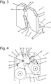
- Fig. 3 and 4 , 7 and 8 disclose an alternative embodiment of an apparatus according to the description, having the same or a similar star wheel 4, first and second tape dispensers 3, 40, knives 31 and tautening device 42.
- the housing is divided basically in two parts 55, 56, the slot 5 extending between and being substantially defined by facing edges 57, 58 of the two parts 55, 56.
- a carrier 59 is provided, connecting the first and second part 55, 56.
- the carrier 59 is substantially U shaped, extending substantially perpendicular to the sides 12, 13 of the housing 2, having a central element 60 and two arms 61, connecting ends of the central element 60 with the first and second part 55, 56 respectively.
- the carrier therefore extends at a distance from the slot 5.
- the apparatus 1 can be mounted with the carrier on a working surface (not shown) such that a bundle of products such as flowers with stems S can be pushed from the slot 5 through the outlet opening 10 further in the direction of movement they had when passing through the slot 5.
- the embodiments are disclosed having the slot 5 or at least the line L extending substantially vertically. It is however obviously possible to have the slot extend in any desired direction and position, for example substantially horizontally or inclined relative to a horizontal and vertical plane.
- the inlet opening 9 and first cell 19 can have corresponding widths. In another embodiment the width of the first cell 19 can differ from the inlet 9, for example smaller.
- the width B1 can for example be between 20 and 100 mm, for example between 30 and 80 mm. In an example the width B1 can be about 30 mm, about 40 mm or about 50 mm.
- the star wheel can have a diameter of any size, for example between 100 and 500 mm. In an example the star wheel can have a diameter of between 200 and 300 mm, for example about 240 to 250 mm. These sizes are only given by way of example.
- the star wheel 4 need not be circular. In an embodiment different star wheels 4 can be provided, interchangeable in the same housing.
- Different star wheels 4 can have for example but not limited to different positions of the first and second cells, different numbers of such cells, different sizes of first and/or second cells or combinations thereof, suitable for for example different sizes of bundles of products or bags or different products.
- Star wheels can have cells having for example a padding for protecting products from damage by the forces exerted thereon when being bundled, tied and/or sealed.
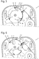
- Fig. 4A and B and fig. 9A - E show embodiments of a knife 31 in a second cell 20, movable by a system 101.
- the knife instead of the knife it can also be an anvil 31B movable in the star wheel 4, which anvil can then be pushed towards a knife 31 in the housing, for cutting the tape or tapes.
- Fig. 4A and B show a knife 31 mounted on a cylinder 102 which can be operated for moving the knife 31 between the first position, shown in solid lines, and a second position, shown in broken lines in fig. 9 .
- an operating system 101 can be provided, schematically shown as a pump symbol 103.
- the second cell 20 has a relatively wide width B2.
- the cylinder 102 is mounted on a rails 32, such that the knife 31 can be repositioned in the cell 20 in substantially tangential direction Bs.
- the first position is shown, in which the cutting edge 31A is below the periphery 21, i.e. between the periphery 21 and an axis of rotation of the wheel 4.
- the knife In fig. 4B the knife is shown in the second position, in which the knife edge 31A extends outside the star wheel or beyond the periphery 21.
- the cutting edge 31A is pushed against an anvil 31B, through the tape 39 or combination of tapes 39, 41, thus cutting the tape or tapes.
- fig. 9A a similar construction as shown in fig. 4A and B is shown, in which however the width B2 of the second cell 20 measured along the periphery 21 is substantially equal to the width Wk of the knife 31.
- the knife 31 is guided by the side surfaces 26, 27 of the cell 20.
- a knife 31 and second cell 20 are shown, similar to fig. 9A , in which the anvil 31B is provided to one or opposite sides of the cutting edge 31A of the knife 31.
- a knife 31 is positioned stationary in a second cell 20, with a cutting edge 31A in or adjacent to the periphery 21.
- an anvil 31B is movable by a system 101, here shown as comprising a cylinder 102 for moving the anvil 31B against the knife's cutting edge 31A, for cutting the tape or tapes.
- a knife 31 is shown in a second cell 20, similar to fig. 9A and 9B , in which the movement of the knife between the first and second position is initiated by a cam 104 on an axis 15 of rotation of the star wheel 4.
- a pusher 105 of the knife 31 will engage the cam 104, pushing the knife into the second position, as shown in fig. 9D to the right.
- the knife When rotating the star wheel 4 further in direction R, the knife will be moved back into the first position, for example by a spring, mechanically, pneumatically, or for example by using the knife as a piston in the second cell 20, sealed such that the movement into the second position creates a partly vacuum behind the knife, biasing the knife towards the first position.
- a knife 31 is shown similar to that of e.g. fig. 9A and B , wherein additionally an anvil 31B is shown, similar to that of fig. 9C , such that both an anvil and a knife can move for cutting the tape or tapes.
- FIG. 9F part of an apparatus is shown in which the knife 31 is supported on a spring 31D which biases the knife 31 in an outward direction K, preferably substantially radially.
- a guide element 110 such as for example a wheel or bearing, can be connected to the knife 31 or knife carrier 31C, which can be guided by a guide 111, for example a stationary guide extending along the wheel 4, such that over a relevant part of a rotation of the wheel 4 the knife 31 is pushed inward, towards the axis 15 of the star wheel 4, against the biasing force of the spring 31D.
- the guide 111 may be interrupted or have an appropriate outward curve 111A, for allowing the spring 31D to force the knife 31 outward.
- the guide 111 is formed such that after cutting the knife 31 is pushed back inward again by the guide element 110. Similar guides and guide elements can be used, also in other embodiments of the disclosure, for moving the knife 31 or anvil in at least one direction.
- a side view is shown, showing a knife 31 which can move in a substantially axial direction K, from a first position, shown in solid lines, substantially next to a side of the star wheel to a second position, shown substantially in broken lines, extending through a cell 19, 20, especially a second cell 20, cutting the or each tape 39, 41 during said movement from the first to the second position.
- the cutting edge 31A of the knife 31 may extend at an angle relative to the direction of movement K between the first and second position.
- Fig. 9H discloses an embodiment of a knife 31, carried on a carrier 31C which is pivotable around an axis 121 extending substantially parallel to the axis 15 of the wheel 4.
- the carrier 31C may be hooked.
- a first end 112 of the carrier 31C carries the knife 31, the opposite end 114 carries a guide element 110, which with the knife 31 in the first position, shown substantially in solid lines, is in a position outward from the axis 15.
- a guide 111 is provided along part of the star wheel 4 which is engaged or can be engaged by the guide element 110 and which is profiled such that it can guide the guide element 110 in a direction substantially towards the axis 15 when rotating the star wheel 4, in direction W, thereby pivoting the carrier 31C and thus forcing the knife to the second position, shown substantially in broken lines, hence cutting tape.
- the carrier 31C can be biased towards the first position, for example by a spring 122 and/or the guide 111 may be provided with a guide part for guiding the guide element 110 back to the first position.
- one or more knifes 31 can be fixed in the wheel 4, having a cutting edge 31 extending outward, wherein an anvil 31B is movable towards the knife, for cutting the or each tape and/or wherein a tape tautening system is provided for pulling the tape taut over the periphery during cutting.
- Figs. 10 - 12 show a further embodiment of an apparatus 1, again comprising a housing 2, at least a first tape dispenser 3 and a star wheel 4.
- a slot 5 is again defined by the housing 2, extending between an inlet 9 and an outlet 10.
- the star wheel 4 extends partly in the slot 5. Products fed through the slot 5 therefore have to engage the star wheel 4.
- the star wheel 4 is substantially the same as disclosed in the previous figures.
- star wheels 4 could be used having the first and second cells 19, 20 distributed differently, for example evenly spaced around the periphery, whereas the cells 19, 20 could all have the same sizes.
- an urging device 62 is provided, at least partly upstream of the star wheel 4.
- a support surface 63 is provided at least on one side of the slot 5, for supporting products to be tied and/or a transport device fed over the support surface 63.
- Such transport device can for example be a substantially flexible conveyer 100, which can in embodiments have a relatively soft top side for supporting the products or parts thereof. As can be seen in for example fig.
- the support surface 63 can have a wavy portion 64 next to the star wheel 4, such that when the support surface 63 extends substantially horizontally a first part 65 of the transport surface 63 next to the star wheel 4 extends higher than an axis 15 of the star wheel 4 and two adjacent parts 66 of the supporting surface 63 extend on either side of the first part 65 at a lower level.
- the structure is preferably chosen such that when a first cell 19 is open to the inlet opening 9, an edge flush with the transport surface or transport element supported thereon, another first cell is open to the outlet in a similar manner, whereas the curvature of the wavy part is such that upon rotation of the star wheel to bring the relevant cell from the inlet side to the outlet side, a bottom portion 67 of the cell follows the wavy pattern of the first part 65, thus allowing support of the product or products by the supporting surface, directly or indirectly, during such movement.
- the urging device 62 can have a central portion 68, mounted on or formed by an axis of rotation 69, preferably extending substantially parallel to the axis 15 of the star wheel 4.
- the urging device comprises three pairs of protrusions or fingers 70, extending substantially tangential to the axis 69, at even angles ⁇ of 120 degrees, between their length directions T. Of each pair the fingers 70 are spaced apart in the length direction 69L of the axis 69, such that of each pair the fingers extend on opposite sides of the star wheel 4, at least partly, as is especially clear from fig. 11 .
- the star wheel 4 and the urging device 62 have the same direction of rotation 71, in fig.
- Each finger 70 has, seen in the direction of rotation 71, a forward side forming an edge portion 72 for urging products into a cell 19 of the star wheel.
- This edge portion can be substantially straight and substantially parallel to the length direction T of the finger 70.
- the opposite, trailing side 73 of the fingers 70 can extend at a slight angle relative to the length direction T and/or the edge portion 72, and there can be a bent transition position 74 between the edge portion 72 of one finger and the trailing side 73 of the an adjacent finger 70.
- the edge portion 72 can be brought into a position in which it extends substantially parallel to and substantially at the same level as the adjacent support surface 63. In fig.
- a sensor 75 is mounted, such as for example an optical sensor, registering during use movement of products into the slot 5, over fingers 70 of the urging device 62.
- the pressing device 76 comprises two substantially parallel arms 77, extending partly on opposite sides of the star wheel 4, above the fingers 70.
- the arms 77 are mounted on a common carrier 78, mounted on an axis of rotation 79 and biased in a downward direction P, for example by one or more springs 80 and/or gravity.
- the arms 77 can rest on ends 81 of the fingers 70, such that a rotation of the urging device 62 will move the arms up and down, pivoting around the axis 79.
- N could also be a different number, for example but not limited to 2 or 3.
- a device or apparatus 1 is shown, according to fig. 10 - 12 .
- Such device can be used as follows, referring also to the previous description of other embodiments.
- a product or bundle of products 51 such as flowers, vegetables, rod like elements or the like, which may or may not be enclosed at least partly in a wrap or bag, can be fed into the slot 5 from the inlet 9, over a pair of fingers 70.
- stems 90 of a bundle of flowers are shown as a bundle of products 51 to be tied.
- a control unit 91 will drive the star wheel 4 and the urging device 62 in the direction 71, such that the edge portion 72 will urge the stems 90 together and into the cell 19 of the star wheel 4, against the tape 39 extending over said cell 19.
- the knife 31 will then be moved from the first to the second position, preferably out of and back into the relevant second cell 20, for cutting the tape 39 or combined tapes 39, 41, such that the tied stems 90 or at least products 51 can be removed when the star wheel is rotated further, such that the relevant cell 19 holding the stems 90 will be flush with the slot 5 again.
- the star wheel 4 and urging device 62 will be rotated over the same angle of approximately 120 degrees.
- the products can be brought into and/or held in a compact bundle during tying thereof.
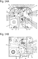
- fig. 14A and B schematically two embodiments are shown of an apparatus 1, for example according to fig. 2 and 12 respectively, combined with a device 95 for feeding containers or other items 96 to the tape 39 between the first dispenser 3 and the slot 5.
- the device 95 comprises or is formed by a pick and place type robot 97, picking containers or items 96 from a supply and pushing the container or item 96 against the adhesive side of the tape 39 at a first cell 10, such that when released by the robot 97 the container or item 96 will rotate with the star wheel 4 towards the inlet side 9 of the slot.
- the device 95 comprises or is formed by a pick and place type robot 97, picking containers or items 96 from a supply and pushing the container or item 96 against the adhesive side of the tape 39 at a first cell 10, such that when released by the robot 97 the container or item 96 will rotate with the star wheel 4 towards the inlet side 9 of the slot.
- the device 95 comprises a movable table 98 below the star wheel 4, on which a container or item 96 is placed, for example by a transport element such as but not limited to a conveyer, or a robot.
- the table is then pushed up, for example pneumatically or hydraulically, electrically or mechanically, such that the container or item 96 is adhered to the adhesive side of the tape 39, preferably in a position at a first cell 19.
- the star wheel 4 is then rotated such that the said cell 19 comes flush with the slot, the item or container 96 will be facing the slot inlet side 9.
- Alternative solutions for attaching the containers or items 96 can be envisaged and will be directly clear to the person skilled in the art.
- the belt 99 supplying the items or containers 96 could be fed directly under the star wheel, such that the items or containers 96 are adhered to the tape 39 directly and lifted off the belt by rotation of the star wheel 4.
- a product or bundle of products 51 such as the stems 90 are forced into the relevant cell 19, pushing the tape 39 into the cell, the container or item 96 will be enclosed between the tape 39 and the product or bundle of products 51, such that it will be tied to the product or bundle 51 simultaneously.
- An example of a container or item 96 can be, but is not limited to a bag, sachet, flask, bottle, leaflet, gift or the like.
- bundling flowers the item 96 can for example be a sachet containing nutrition or fertiliser.
- packaging produce the item can for example be additives to be used with the produce, such as but not limited to herbs, spices or the like.
- first and a second dispenser 3, 40 there is a first and a second dispenser 3, 40.
- one tape dispenser only, especially the first dispenser for the adhesive tape.
- At least one of the knife arrangement or knife carrier, the star wheel and the urging device and/or pressing device, and/or at least one dispenser 3, 40 could be connected to a counter, registering the number of revolutions or cutting actions during a period, which will be indicative for the number of products or bundles of products that have been tied during that period. This information can be read directly from the counter or could be transferred to another location, for example by wireless, sms or the like.
- Fig. 15 schematically shows in side view part of an embodiment of an apparatus 1 according to the disclosure. Especially a star wheel 4 rotating around a central axis 15. A series of first cells 19 is provided, evenly spaced around the periphery, for receiving parts of products or bundles of products to the taped.
- Fig. 16 shows a substantially transparent view of part of a star wheel 4 of an apparatus according to the disclosure, especially but not limited to fig. 15 .
- Fig. 17 schematically shows a knife 31 with carrier 31C and operating mechanism 101, for an apparatus 1 of the disclosure.
- the knife 31 has a serrated cutting edge 31A, which can be used for any knife 31 according to the disclosure.
- the cutting edge 31A can have any suitable shape and configuration.
- the knife 31 is carried on a rod shaped carrier 31C, which at one end comprises a first guide element 110 near a first, outward facing end 112 of the carrier 31C, next to the knife 31, and a second guide element 113 at an opposite end 114.
- the star wheel 4 comprises a series of radial tunnels 115, through which a knife carrier 31C extends, such that the first end 112 extends close to the periphery 21, whereas the opposite end 114 extends close to the axis 15.
- a guide curve 116 in this embodiment is provided stationary, extending around the axis 15, provided with a cam 117, in fig. 15 shown at a top of the curve 116, i.e. pointing upward.
- the second guide element 113 for example a wheel or bearing, is guided on the guide curve 116.
- the second guide element 113 When rotating the star wheel 4 in the appropriate direction W the second guide element 113 will be guided up along a flank 118 of the cam 117, thereby forcing the knife 31 from a first position into a second position, bringing the cutting edge 31A from within the periphery to a position outside the periphery, thereby cutting tape.
- a guide 111 is provided, by which the first guide element 110 can be guided, for example as discussed before.
- the guide 111 may be stationary or it may be movable, for example pivotable around an axis 119 as shown in fig. 15 , for example biased in a direction towards the star wheel 4 by a spring 120.
- the guide 111 is provided such that after having cut tape the knife 31 is forced back into the first position by guiding the first guide element 110 along said guide 111, whereas the second guide element 113 is allowed to run off the cam 117 upon further rotation of the star wheel 4 in direction W.
- other means can be provided for pushing and/or pulling the knife back to the first position, for example by providing a guide along the curve 116, by spring means biasing the knife carrier 31C towards the first position or by mechanical or electro mechanical means, such a motor, magnet or the like.
- the star wheel can be driven differently, for example through a step motor engaging the axis 15 or by the feeding and/or discharging means.
- the knife carrier can be made differently, for example as an arm extending partly in the outlet opening 10, such that when the products are moved through the outlet opening the knife 31 is forced into a second cell 20, cutting loose the stems 90.
- a star wheel in the form of an endless star belt, formed as a belt having a series of cells in an outwardly facing surface, guided over at least two end wheels, such that a series of cells 19, 20 is fed along the guide surface, allowing a series of bundles to be handled at the same time.
- Means can be provided to print information on and/or in the tape and/or the foil strip, such as sealing date, expiration date of the product, packing apparatus identification, advertisements or other information.
- the width of the strip of tape 39 is about the same as the width of the tape 41.
- the second tape 41 can have a greater width in order to provide further information, such as user information, warranties and other communications.
- the urging means can be designed differently, for example moving substantially linearly.
- a transport belt of conveyer could be provided on both sides of the star wheel, or on only one side, and could be provided with elements for urging the products into a cell of the star wheel.
- the pressing device could also be designed differently, for example a flexible element extending alongside one or both of the sides of the star wheel, at an upper side of the cells 19 when opening towards the inlet 9 and/or outlet 10, for holding the products at a lower side 67 of the cell 19.
Landscapes
- Engineering & Computer Science (AREA)
- Mechanical Engineering (AREA)
- Life Sciences & Earth Sciences (AREA)
- Agronomy & Crop Science (AREA)
- Package Closures (AREA)
- Auxiliary Devices For And Details Of Packaging Control (AREA)
Claims (14)
- Vorrichtung zum Versiegeln oder Binden von Produkten (1), umfassend ein Gehäuse (2) mit wenigstens einem ersten Bandspender (3) und einem Sternrad (4), einem Schlitz (5), der von dem oder durch das Gehäuse (2) definiert ist, wobei sich das Sternrad (4) wenigstens teilweise in dem Schlitz (5) erstreckt, wobei das Sternrad (4) wenigstens eine Reihe von ersten Zellen (19) umfasst, wobei die ersten Zellen (19) in dem Sternrad (4) intermittierend angeordnet sind, wobei jede Zelle zu einem Umfang des Sternrads (4) und zwei gegenüberliegenden Seiten davon offen ist, dadurch gekennzeichnet, dass das Sternrad (4) oder das Gehäuse (2) mit wenigstens einem Messer (31) versehen ist und vorzugsweise das andere von dem Sternrad (4) und dem Gehäuse (2) mit einem Amboss (31B) versehen ist, wobei das wenigstens eine Messer (31), das in dem Sternrad (4) vorgesehen ist, relativ zum Sternrad (4) bewegbar ist und/oder wobei wenigstens ein Amboss (31B) in dem Sternrad (4) relativ zum Sternrad (4) und dem Messer (31) bewegbar ist, wobei das wenigstens eine Messer (31) oder der Amboss (31B), der in dem Sternrad (4) vorgesehen ist, in einer zweiten Zelle (20) des Sternrads (4) vorgesehen ist.
- Vorrichtung nach Anspruch 1, wobei eine Drückvorrichtung (62) vorgesehen ist, die wenigstens einen Randabschnitt (72) aufweist, um wenigstens ein zu bindendes Produkt in eine der Zellen (19), insbesondere eine erste Zelle, zu drücken, wobei der Randabschnitt (72) Teil eines Vorsprungs oder eines Fingers (70) an einem oder eines sich drehenden Elements ist, das derart drehbar ist, dass der Vorsprung oder der Finger (70) wenigstens teilweise entlang des Sternrads (4) an einem Teil der Zelle vorbei gedreht werden kann, in die das wenigstens eine Produkt gedrückt wird.
- Vorrichtung nach Anspruch 1 oder 2, wobei das wenigstens eine Messer (31) in dem Sternrad vorgesehen ist und wenigstens ein Amboss (31B) in dem Gehäuse (2) vorgesehen ist, wobei vorzugsweise wenigstens das wenigstens eine Messer (31) relativ zum Sternrad in einer im Wesentlichen radialen Richtung bewegbar ist, so dass eine Schneidkante (31A) des Messers (31) gegen den wenigstens einen Amboss (31B) bewegt wird.
- Vorrichtung nach einem der Ansprüche 1 bis 3, wobei mehrere Messer (31) in dem Sternrad (4) vorgesehen sind, die vorzugsweise regelmäßig um den Umfang des Sternrads herum beabstandet sind, wobei vorzugsweise jedes Messer (31) gegen denselben Amboss (31B) bewegbar ist.
- Vorrichtung nach einem der vorhergehenden Ansprüche, wobei jedes Messer (31), das von einem Messerträger (31C) getragen wird, der zum Bewegen des Messers (31) in einer im Wesentlichen radialen Richtung des Sternrads (4) ausgelegt ist, wobei das oder jedes Messer (31) vorzugsweise pneumatisch bewegbar ist oder wobei das oder jedes Messer durch wenigstens einen Nocken (104), vorzugsweise einen Nocken (104), der an dem Sternrad oder einer Achse (15) des Sternrads angebracht ist, bewegbar ist.
- Vorrichtung nach einem der vorhergehenden Ansprüche, wobei wenigstens ein Messer (31) in und relativ zum Sternrad (4) bewegbar ist, wobei ein Bandstraffungsmittel vorgesehen ist, um das Band während des Schneidens mit dem wenigstens einen Messer zu straffen.
- Vorrichtung nach einem der Ansprüche 3 bis 6, wobei das oder jedes Messer in eine erste Position gebracht werden kann, in der eine Schneidkante (31A) des Messers in eine Position zwischen dem Umfang (21) des Sternrads (4) und eine Mitte des Sternrads gebracht wird, und eine zweite Position, in der die Schneidkante (31A) am Umfang (21) des Sternrads vorbei bewegt wird.
- Vorrichtung nach einem der vorhergehenden Ansprüche, wobei in Drehrichtung des Sternrads (W) gesehen ein Messer (31) im Sternrad vorgesehen ist, das einer ersten Zelle (19) folgt, wobei vorzugsweise der Abstand zwischen der relevanten ersten Zelle und dem Messer, das der Zelle nachläuft, gemessen entlang des Umfangs (21) des Sternrads, kürzer ist als der Abstand zwischen dem Messer und der nächsten ersten Zelle (19), die dem Messer nachläuft.
- Vorrichtung nach einem der vorhergehenden Ansprüche, wobei die Drückvorrichtung (62) eine erste Anzahl (N1) von Randabschnitten (72) oder Paaren von Randabschnitten (72) aufweist, die um einen Umfang einer Achse oder eines Rades verteilt sind, und das Sternrad eine zweite Anzahl (N2) von ersten Zellen hat, wobei die erste Anzahl (N1) wenigstens eins ist und dem n-fachen der zweiten Anzahl (N2) entspricht, wobei n eine ganze Zahl ist.
- Vorrichtung nach einem der vorhergehenden Ansprüche, wobei eine Pressvorrichtung (76) vorgesehen ist, um ein Produkt oder einen Satz von Produkten in eine Zelle, insbesondere eine erste Zelle, weg von der offenen Seite davon zu pressen, wobei die Pressvorrichtung (76) vorzugsweise wenigstens einen Arm (77) aufweist, der sich entlang eines Teils einer Seite des Sternrads (4) erstreckt, und noch bevorzugter ein Paar Arme (77), die sich entlang eines Teils gegenüberliegender Seiten des Sternrads (4) erstrecken, vorgespannt in der Richtung einer Achse des Sternrads, wobei die Pressvorrichtung (76) vorzugsweise derart vorgesehen ist, dass sie durch Bewegung der Drückvorrichtung (62) und/oder des Sternrades (4) mit dem wenigstens einen Produkt in der relevanten Zelle in und außer Eingriff gebracht wird.
- Vorrichtung nach einem der vorhergehenden Ansprüche, wobei ein Sensor (75) in der Nähe der Drückvorrichtung (62) vorgesehen ist, um die Drückvorrichtung basierend auf der Bewegung wenigstens eines Produkts durch einen Erfassungsbereich des Sensors zu steuern.
- Verfahren zum Versiegeln oder Binden von Produkten, wobei Klebeband (39) über eine offene Seite einer ersten Zelle (19) eines Sternrads (4) geführt wird, wobei eine Klebeseite (49) des Klebebandes (39) dem Sternrad abgewandt ist, wobei ein Produkt oder ein Produktbündel gegen das Band (39) und in die erste Zelle (19) geschoben wird, wobei wenigstens ein Teil des Klebebandes (39) um wenigstens einen Teil des Produkts oder Produktbündels herum geklebt und das Sternrad (4) um eine Achse gedreht wird, wobei das Band (39) um das Produkt oder das Produktbündel herum gebunden wird, wobei das Sternrad (4) weiter gedreht wird und das Band (39) das oder die zwei geklebten Bänder (39) geschnitten werden, wodurch das Bündel aus der Zelle (19) entfernt werden kann, dadurch gekennzeichnet, dass das Band (39) durch Bewegen einer Schneidkante (31 A) eines Messers durch das Band (39) geschnitten wird, durch Bewegen des Messers (31) wenigstens teilweise aus einer zweiten Zelle (20) des Sternrads (4) und/oder durch Bewegen eines Ambosses (31B) wenigstens teilweise aus einer zweiten Zelle (20) des Sternrads (4) gegen das Band (39) gegenüber einer Schneidkante (31A) des Messers (31).
- Verfahren nach Anspruch 12, wobei das Produkt oder Produktbündel durch eine Drückvorrichtung (62) und/oder eine Pressvorrichtung (76) in die erste Zelle (19) hineingeschoben und in dieser gehalten wird.
- Verwendung eines Siegelgerätes mit einem Sternrad (4) mit wenigstens einem bewegbaren Messer oder Amboss, einem Klebebandspender (3), zum Binden von Produkten, insbesondere Frischwaren, wobei Klebeband vom Spender (3) abgegeben und unter Verwendung des Sternrads (4) um wenigstens einen Teil eines Produktbündels herumgewickelt wird, wobei das Produktbündel durch eine Drückvorrichtung (62) in eine erste Zelle (19) geschoben und vorübergehend in dieser gehalten wird und/oder eine Pressvorrichtung (76), und das Band durch Bewegung des in einer zweiten Zelle (20) des Sternrades vorgesehenen Messers oder Ambosses relativ zum Sternrad (4) geschnitten wird.
Applications Claiming Priority (1)
| Application Number | Priority Date | Filing Date | Title |
|---|---|---|---|
| NL2018897A NL2018897B1 (en) | 2017-05-11 | 2017-05-11 | Apparatus and method for sealing or tying products |
Publications (2)
| Publication Number | Publication Date |
|---|---|
| EP3401226A1 EP3401226A1 (de) | 2018-11-14 |
| EP3401226B1 true EP3401226B1 (de) | 2020-04-15 |
Family
ID=59351023
Family Applications (1)
| Application Number | Title | Priority Date | Filing Date |
|---|---|---|---|
| EP18171563.2A Active EP3401226B1 (de) | 2017-05-11 | 2018-05-09 | Vorrichtung und verfahren zum abdichten oder zubinden von produkten und verwendung der vorrichtung |
Country Status (4)
| Country | Link |
|---|---|
| US (1) | US11091282B2 (de) |
| EP (1) | EP3401226B1 (de) |
| ES (1) | ES2796482T3 (de) |
| NL (1) | NL2018897B1 (de) |
Families Citing this family (6)
| Publication number | Priority date | Publication date | Assignee | Title |
|---|---|---|---|---|
| CN109677992B (zh) * | 2018-12-21 | 2023-11-17 | 中国信息通信研究院 | 一种用于串音测试的样品制作系统 |
| CN109515807B (zh) * | 2019-01-25 | 2021-10-15 | 上海懒牛智能科技有限公司 | 全自动pet带打包机 |
| CN112407664B (zh) * | 2020-11-23 | 2025-09-09 | 浙江义乌宝隆包装材料科技有限公司 | 一种塑料袋口集束后的胶带扎口装置 |
| CN113968366B (zh) * | 2021-10-21 | 2023-02-17 | 珠海格力智能装备有限公司 | 粘贴装置 |
| TWI864726B (zh) * | 2023-05-02 | 2024-12-01 | 元貝實業股份有限公司 | 捆包機之切帶機構 |
| US20250026521A1 (en) * | 2023-07-20 | 2025-01-23 | Elizabeth Wong Peterson | Method and apparatus for sealing flexible container |
Family Cites Families (9)
| Publication number | Priority date | Publication date | Assignee | Title |
|---|---|---|---|---|
| GB807665A (en) * | 1956-03-12 | 1959-01-21 | Derby Sealers Inc | A bag-tying machine |
| US2841935A (en) | 1956-03-12 | 1958-07-08 | Derby Sealers Inc | Bag-tying machine |
| NL6804235A (de) * | 1968-03-26 | 1969-09-30 | ||
| GB1584192A (en) * | 1978-01-10 | 1981-02-11 | Metromethods Ltd | Tape applying device |
| JPS58149228A (ja) | 1982-02-19 | 1983-09-05 | 株式会社大生機械 | 包装用結束装置 |
| NL8902097A (nl) * | 1989-08-18 | 1991-03-18 | Henkel Nederland | Zaksluiter. |
| NL2005625C2 (en) * | 2010-11-04 | 2012-05-07 | Duoseal Automatics B V | Apparatus and method for sealing or tying products. |
| NL2005627C2 (en) * | 2010-11-04 | 2012-05-07 | Duoseal Automatics B V | Apparatus and method for sealing or tying products. |
| NL2012818B1 (en) * | 2014-05-15 | 2016-03-02 | Duoseal Automatics B V | Apparatus and method for sealing or tying products. |
-
2017
- 2017-05-11 NL NL2018897A patent/NL2018897B1/nl not_active IP Right Cessation
-
2018
- 2018-05-09 ES ES18171563T patent/ES2796482T3/es active Active
- 2018-05-09 EP EP18171563.2A patent/EP3401226B1/de active Active
- 2018-05-09 US US15/975,392 patent/US11091282B2/en active Active
Non-Patent Citations (1)
| Title |
|---|
| None * |
Also Published As
| Publication number | Publication date |
|---|---|
| EP3401226A1 (de) | 2018-11-14 |
| US20180327123A1 (en) | 2018-11-15 |
| US11091282B2 (en) | 2021-08-17 |
| NL2018897B1 (en) | 2018-11-15 |
| ES2796482T3 (es) | 2020-11-27 |
Similar Documents
| Publication | Publication Date | Title |
|---|---|---|
| US11091282B2 (en) | Apparatus and method for sealing or tying products | |
| US9339998B2 (en) | Apparatus and method for sealing or tying products | |
| CN102227352B (zh) | 用于制造束条包装的方法和装置以及束条包装 | |
| US9469425B2 (en) | Apparatus and method for sealing or tying products | |
| EP1227040B1 (de) | Verfahren und Vorrichtung zum Verpacken eines Rieses von Bögen | |
| JPH03148409A (ja) | 寸法の異なる物品の包装装置 | |
| GB1581674A (en) | Automatic wrapping apparatus | |
| CN103402875A (zh) | 用于制造具有浸泡用产品且具有外包裹封套的过滤袋的机器 | |
| US2626074A (en) | Supplying sheet material articles | |
| JP5155594B2 (ja) | 一連の編集製品をプラスチックフィルムにより包装する自動機械及び方法 | |
| CN209064521U (zh) | 包装机和包装堆叠体 | |
| CN220411080U (zh) | 一种装箱打包系统 | |
| EP3142932B1 (de) | Vorrichtung und verfahren zum umschliessen oder umbinden von produkten | |
| US4716707A (en) | Apparatus for shrink-wrapping articles with handles | |
| JP2007302345A5 (de) | ||
| NL2007689C2 (en) | Apparatus and method for bundling, sealing and/or tying products. | |
| NL2003098C2 (en) | APPARATUS AND METHOD FOR SEALING OR TYING PRODUCTS. | |
| EP2007628A2 (de) | Verfahren und vorrichtung zum einwickeln von süsswarenprodukten | |
| US3237370A (en) | Packaging machine | |
| KR100654332B1 (ko) | 샌드위치 포장대의 포장장치 | |
| US3269078A (en) | Method of packaging articles | |
| WO2014068521A2 (en) | Unit and method for applying an inclined tear strip to a sheet of wrapping material | |
| EP3805124A1 (de) | Verfahren zur herstellung eines beutels aus papiermaterial, maschine zum durchführen dieses verfahrens und mit diesem verfahren hergestellter beutel aus papiermaterial | |
| CA1064381A (en) | Automatic wrapping apparatus | |
| WO2004071753A1 (en) | Method and apparatus for applying tags to objects |
Legal Events
| Date | Code | Title | Description |
|---|---|---|---|
| PUAI | Public reference made under article 153(3) epc to a published international application that has entered the european phase |
Free format text: ORIGINAL CODE: 0009012 |
|
| STAA | Information on the status of an ep patent application or granted ep patent |
Free format text: STATUS: THE APPLICATION HAS BEEN PUBLISHED |
|
| AK | Designated contracting states |
Kind code of ref document: A1 Designated state(s): AL AT BE BG CH CY CZ DE DK EE ES FI FR GB GR HR HU IE IS IT LI LT LU LV MC MK MT NL NO PL PT RO RS SE SI SK SM TR |
|
| AX | Request for extension of the european patent |
Extension state: BA ME |
|
| STAA | Information on the status of an ep patent application or granted ep patent |
Free format text: STATUS: REQUEST FOR EXAMINATION WAS MADE |
|
| 17P | Request for examination filed |
Effective date: 20190509 |
|
| RBV | Designated contracting states (corrected) |
Designated state(s): AL AT BE BG CH CY CZ DE DK EE ES FI FR GB GR HR HU IE IS IT LI LT LU LV MC MK MT NL NO PL PT RO RS SE SI SK SM TR |
|
| RIC1 | Information provided on ipc code assigned before grant |
Ipc: B65B 25/02 20060101AFI20190605BHEP Ipc: B65B 67/06 20060101ALI20190605BHEP Ipc: B65B 51/06 20060101ALI20190605BHEP Ipc: B65B 27/10 20060101ALI20190605BHEP |
|
| GRAP | Despatch of communication of intention to grant a patent |
Free format text: ORIGINAL CODE: EPIDOSNIGR1 |
|
| STAA | Information on the status of an ep patent application or granted ep patent |
Free format text: STATUS: GRANT OF PATENT IS INTENDED |
|
| INTG | Intention to grant announced |
Effective date: 20190724 |
|
| GRAJ | Information related to disapproval of communication of intention to grant by the applicant or resumption of examination proceedings by the epo deleted |
Free format text: ORIGINAL CODE: EPIDOSDIGR1 |
|
| STAA | Information on the status of an ep patent application or granted ep patent |
Free format text: STATUS: REQUEST FOR EXAMINATION WAS MADE |
|
| INTC | Intention to grant announced (deleted) | ||
| GRAP | Despatch of communication of intention to grant a patent |
Free format text: ORIGINAL CODE: EPIDOSNIGR1 |
|
| STAA | Information on the status of an ep patent application or granted ep patent |
Free format text: STATUS: GRANT OF PATENT IS INTENDED |
|
| INTG | Intention to grant announced |
Effective date: 20191202 |
|
| GRAS | Grant fee paid |
Free format text: ORIGINAL CODE: EPIDOSNIGR3 |
|
| GRAA | (expected) grant |
Free format text: ORIGINAL CODE: 0009210 |
|
| STAA | Information on the status of an ep patent application or granted ep patent |
Free format text: STATUS: THE PATENT HAS BEEN GRANTED |
|
| RAP1 | Party data changed (applicant data changed or rights of an application transferred) |
Owner name: DUOSEAL AUTOMATICS B.V. |
|
| RIN1 | Information on inventor provided before grant (corrected) |
Inventor name: AARTS, GUIDO MAURINUS ADRIANA MARIA |
|
| AK | Designated contracting states |
Kind code of ref document: B1 Designated state(s): AL AT BE BG CH CY CZ DE DK EE ES FI FR GB GR HR HU IE IS IT LI LT LU LV MC MK MT NL NO PL PT RO RS SE SI SK SM TR |
|
| REG | Reference to a national code |
Ref country code: CH Ref legal event code: EP |
|
| REG | Reference to a national code |
Ref country code: DE Ref legal event code: R096 Ref document number: 602018003712 Country of ref document: DE |
|
| REG | Reference to a national code |
Ref country code: IE Ref legal event code: FG4D |
|
| REG | Reference to a national code |
Ref country code: AT Ref legal event code: REF Ref document number: 1257003 Country of ref document: AT Kind code of ref document: T Effective date: 20200515 |
|
| REG | Reference to a national code |
Ref country code: NL Ref legal event code: FP |
|
| REG | Reference to a national code |
Ref country code: LT Ref legal event code: MG4D |
|
| PG25 | Lapsed in a contracting state [announced via postgrant information from national office to epo] |
Ref country code: PT Free format text: LAPSE BECAUSE OF FAILURE TO SUBMIT A TRANSLATION OF THE DESCRIPTION OR TO PAY THE FEE WITHIN THE PRESCRIBED TIME-LIMIT Effective date: 20200817 Ref country code: NO Free format text: LAPSE BECAUSE OF FAILURE TO SUBMIT A TRANSLATION OF THE DESCRIPTION OR TO PAY THE FEE WITHIN THE PRESCRIBED TIME-LIMIT Effective date: 20200715 Ref country code: LT Free format text: LAPSE BECAUSE OF FAILURE TO SUBMIT A TRANSLATION OF THE DESCRIPTION OR TO PAY THE FEE WITHIN THE PRESCRIBED TIME-LIMIT Effective date: 20200415 Ref country code: FI Free format text: LAPSE BECAUSE OF FAILURE TO SUBMIT A TRANSLATION OF THE DESCRIPTION OR TO PAY THE FEE WITHIN THE PRESCRIBED TIME-LIMIT Effective date: 20200415 Ref country code: SE Free format text: LAPSE BECAUSE OF FAILURE TO SUBMIT A TRANSLATION OF THE DESCRIPTION OR TO PAY THE FEE WITHIN THE PRESCRIBED TIME-LIMIT Effective date: 20200415 Ref country code: IS Free format text: LAPSE BECAUSE OF FAILURE TO SUBMIT A TRANSLATION OF THE DESCRIPTION OR TO PAY THE FEE WITHIN THE PRESCRIBED TIME-LIMIT Effective date: 20200815 Ref country code: GR Free format text: LAPSE BECAUSE OF FAILURE TO SUBMIT A TRANSLATION OF THE DESCRIPTION OR TO PAY THE FEE WITHIN THE PRESCRIBED TIME-LIMIT Effective date: 20200716 |
|
| REG | Reference to a national code |
Ref country code: AT Ref legal event code: MK05 Ref document number: 1257003 Country of ref document: AT Kind code of ref document: T Effective date: 20200415 |
|
| REG | Reference to a national code |
Ref country code: ES Ref legal event code: FG2A Ref document number: 2796482 Country of ref document: ES Kind code of ref document: T3 Effective date: 20201127 |
|
| PG25 | Lapsed in a contracting state [announced via postgrant information from national office to epo] |
Ref country code: RS Free format text: LAPSE BECAUSE OF FAILURE TO SUBMIT A TRANSLATION OF THE DESCRIPTION OR TO PAY THE FEE WITHIN THE PRESCRIBED TIME-LIMIT Effective date: 20200415 Ref country code: LV Free format text: LAPSE BECAUSE OF FAILURE TO SUBMIT A TRANSLATION OF THE DESCRIPTION OR TO PAY THE FEE WITHIN THE PRESCRIBED TIME-LIMIT Effective date: 20200415 Ref country code: HR Free format text: LAPSE BECAUSE OF FAILURE TO SUBMIT A TRANSLATION OF THE DESCRIPTION OR TO PAY THE FEE WITHIN THE PRESCRIBED TIME-LIMIT Effective date: 20200415 Ref country code: BG Free format text: LAPSE BECAUSE OF FAILURE TO SUBMIT A TRANSLATION OF THE DESCRIPTION OR TO PAY THE FEE WITHIN THE PRESCRIBED TIME-LIMIT Effective date: 20200715 |
|
| PG25 | Lapsed in a contracting state [announced via postgrant information from national office to epo] |
Ref country code: AL Free format text: LAPSE BECAUSE OF FAILURE TO SUBMIT A TRANSLATION OF THE DESCRIPTION OR TO PAY THE FEE WITHIN THE PRESCRIBED TIME-LIMIT Effective date: 20200415 |
|
| REG | Reference to a national code |
Ref country code: DE Ref legal event code: R097 Ref document number: 602018003712 Country of ref document: DE |
|
| PG25 | Lapsed in a contracting state [announced via postgrant information from national office to epo] |
Ref country code: MC Free format text: LAPSE BECAUSE OF FAILURE TO SUBMIT A TRANSLATION OF THE DESCRIPTION OR TO PAY THE FEE WITHIN THE PRESCRIBED TIME-LIMIT Effective date: 20200415 Ref country code: SM Free format text: LAPSE BECAUSE OF FAILURE TO SUBMIT A TRANSLATION OF THE DESCRIPTION OR TO PAY THE FEE WITHIN THE PRESCRIBED TIME-LIMIT Effective date: 20200415 Ref country code: AT Free format text: LAPSE BECAUSE OF FAILURE TO SUBMIT A TRANSLATION OF THE DESCRIPTION OR TO PAY THE FEE WITHIN THE PRESCRIBED TIME-LIMIT Effective date: 20200415 Ref country code: DK Free format text: LAPSE BECAUSE OF FAILURE TO SUBMIT A TRANSLATION OF THE DESCRIPTION OR TO PAY THE FEE WITHIN THE PRESCRIBED TIME-LIMIT Effective date: 20200415 Ref country code: CZ Free format text: LAPSE BECAUSE OF FAILURE TO SUBMIT A TRANSLATION OF THE DESCRIPTION OR TO PAY THE FEE WITHIN THE PRESCRIBED TIME-LIMIT Effective date: 20200415 Ref country code: RO Free format text: LAPSE BECAUSE OF FAILURE TO SUBMIT A TRANSLATION OF THE DESCRIPTION OR TO PAY THE FEE WITHIN THE PRESCRIBED TIME-LIMIT Effective date: 20200415 Ref country code: IT Free format text: LAPSE BECAUSE OF FAILURE TO SUBMIT A TRANSLATION OF THE DESCRIPTION OR TO PAY THE FEE WITHIN THE PRESCRIBED TIME-LIMIT Effective date: 20200415 Ref country code: EE Free format text: LAPSE BECAUSE OF FAILURE TO SUBMIT A TRANSLATION OF THE DESCRIPTION OR TO PAY THE FEE WITHIN THE PRESCRIBED TIME-LIMIT Effective date: 20200415 |
|
| PLBE | No opposition filed within time limit |
Free format text: ORIGINAL CODE: 0009261 |
|
| STAA | Information on the status of an ep patent application or granted ep patent |
Free format text: STATUS: NO OPPOSITION FILED WITHIN TIME LIMIT |
|
| PG25 | Lapsed in a contracting state [announced via postgrant information from national office to epo] |
Ref country code: PL Free format text: LAPSE BECAUSE OF FAILURE TO SUBMIT A TRANSLATION OF THE DESCRIPTION OR TO PAY THE FEE WITHIN THE PRESCRIBED TIME-LIMIT Effective date: 20200415 Ref country code: SK Free format text: LAPSE BECAUSE OF FAILURE TO SUBMIT A TRANSLATION OF THE DESCRIPTION OR TO PAY THE FEE WITHIN THE PRESCRIBED TIME-LIMIT Effective date: 20200415 |
|
| 26N | No opposition filed |
Effective date: 20210118 |
|
| PG25 | Lapsed in a contracting state [announced via postgrant information from national office to epo] |
Ref country code: LU Free format text: LAPSE BECAUSE OF NON-PAYMENT OF DUE FEES Effective date: 20200509 |
|
| PG25 | Lapsed in a contracting state [announced via postgrant information from national office to epo] |
Ref country code: IE Free format text: LAPSE BECAUSE OF NON-PAYMENT OF DUE FEES Effective date: 20200509 |
|
| PG25 | Lapsed in a contracting state [announced via postgrant information from national office to epo] |
Ref country code: SI Free format text: LAPSE BECAUSE OF FAILURE TO SUBMIT A TRANSLATION OF THE DESCRIPTION OR TO PAY THE FEE WITHIN THE PRESCRIBED TIME-LIMIT Effective date: 20200415 |
|
| REG | Reference to a national code |
Ref country code: CH Ref legal event code: PL |
|
| PG25 | Lapsed in a contracting state [announced via postgrant information from national office to epo] |
Ref country code: CH Free format text: LAPSE BECAUSE OF NON-PAYMENT OF DUE FEES Effective date: 20210531 Ref country code: LI Free format text: LAPSE BECAUSE OF NON-PAYMENT OF DUE FEES Effective date: 20210531 |
|
| PG25 | Lapsed in a contracting state [announced via postgrant information from national office to epo] |
Ref country code: TR Free format text: LAPSE BECAUSE OF FAILURE TO SUBMIT A TRANSLATION OF THE DESCRIPTION OR TO PAY THE FEE WITHIN THE PRESCRIBED TIME-LIMIT Effective date: 20200415 Ref country code: MT Free format text: LAPSE BECAUSE OF FAILURE TO SUBMIT A TRANSLATION OF THE DESCRIPTION OR TO PAY THE FEE WITHIN THE PRESCRIBED TIME-LIMIT Effective date: 20200415 Ref country code: CY Free format text: LAPSE BECAUSE OF FAILURE TO SUBMIT A TRANSLATION OF THE DESCRIPTION OR TO PAY THE FEE WITHIN THE PRESCRIBED TIME-LIMIT Effective date: 20200415 |
|
| PG25 | Lapsed in a contracting state [announced via postgrant information from national office to epo] |
Ref country code: MK Free format text: LAPSE BECAUSE OF FAILURE TO SUBMIT A TRANSLATION OF THE DESCRIPTION OR TO PAY THE FEE WITHIN THE PRESCRIBED TIME-LIMIT Effective date: 20200415 |
|
| PGFP | Annual fee paid to national office [announced via postgrant information from national office to epo] |
Ref country code: NL Payment date: 20250401 Year of fee payment: 8 |
|
| PGFP | Annual fee paid to national office [announced via postgrant information from national office to epo] |
Ref country code: DE Payment date: 20250521 Year of fee payment: 8 |
|
| PGFP | Annual fee paid to national office [announced via postgrant information from national office to epo] |
Ref country code: GB Payment date: 20250527 Year of fee payment: 8 |
|
| PGFP | Annual fee paid to national office [announced via postgrant information from national office to epo] |
Ref country code: BE Payment date: 20250521 Year of fee payment: 8 |
|
| PGFP | Annual fee paid to national office [announced via postgrant information from national office to epo] |
Ref country code: FR Payment date: 20250528 Year of fee payment: 8 |
|
| PGFP | Annual fee paid to national office [announced via postgrant information from national office to epo] |
Ref country code: ES Payment date: 20250630 Year of fee payment: 8 |