EP3401242B1 - Hängefördereinrichtung - Google Patents
Hängefördereinrichtung Download PDFInfo
- Publication number
- EP3401242B1 EP3401242B1 EP18180004.6A EP18180004A EP3401242B1 EP 3401242 B1 EP3401242 B1 EP 3401242B1 EP 18180004 A EP18180004 A EP 18180004A EP 3401242 B1 EP3401242 B1 EP 3401242B1
- Authority
- EP
- European Patent Office
- Prior art keywords
- suspended
- interchangeable
- conveyor device
- side wall
- pouch
- Prior art date
- Legal status (The legal status is an assumption and is not a legal conclusion. Google has not performed a legal analysis and makes no representation as to the accuracy of the status listed.)
- Active
Links
Images


Classifications
-
- B—PERFORMING OPERATIONS; TRANSPORTING
- B65—CONVEYING; PACKING; STORING; HANDLING THIN OR FILAMENTARY MATERIAL
- B65G—TRANSPORT OR STORAGE DEVICES, e.g. CONVEYORS FOR LOADING OR TIPPING, SHOP CONVEYOR SYSTEMS OR PNEUMATIC TUBE CONVEYORS
- B65G17/00—Conveyors having an endless traction element, e.g. a chain, transmitting movement to a continuous or substantially-continuous load-carrying surface or to a series of individual load-carriers; Endless-chain conveyors in which the chains form the load-carrying surface
- B65G17/30—Details; Auxiliary devices
- B65G17/48—Controlling attitudes of load-carriers during movement
- B65G17/485—Controlling attitudes of load-carriers during movement the load carriers being suspended
-
- B—PERFORMING OPERATIONS; TRANSPORTING
- B65—CONVEYING; PACKING; STORING; HANDLING THIN OR FILAMENTARY MATERIAL
- B65G—TRANSPORT OR STORAGE DEVICES, e.g. CONVEYORS FOR LOADING OR TIPPING, SHOP CONVEYOR SYSTEMS OR PNEUMATIC TUBE CONVEYORS
- B65G17/00—Conveyors having an endless traction element, e.g. a chain, transmitting movement to a continuous or substantially-continuous load-carrying surface or to a series of individual load-carriers; Endless-chain conveyors in which the chains form the load-carrying surface
- B65G17/20—Conveyors having an endless traction element, e.g. a chain, transmitting movement to a continuous or substantially-continuous load-carrying surface or to a series of individual load-carriers; Endless-chain conveyors in which the chains form the load-carrying surface comprising load-carriers suspended from overhead traction chains
Definitions
- the present invention relates to an overhead conveyor device, comprising a guide rail arrangement and a hanging pocket system, comprising at least two, preferably a plurality of hanging pockets movably guided on the guide rail arrangement as conveyed goods container for transporting conveyed goods in an overhead conveyor device, with a first pocket side wall and a second pocket side wall, which Opposite each other, delimit a conveyed goods receiving area between them and are connected to one another in a folding connection area in such a way that they can be opened and closed to open and close the conveyed goods receiving area, and with a suspension means for attaching the hanging bag to a guide rail arrangement of an overhead conveyor.
- the first pocket side wall has at least one rigid edge contour area and is connected to it pivotably about a pivot axis with the attachment means, and the second pocket side wall is connected to the attachment means or can be acted upon by the attachment means that by pivoting the first pocket side wall about the pivot axis the first and the second bag side wall can be unfolded and collapsed.
- Such hanging pockets are for example from the WO 2014/012965 A1 known.
- the hanging pockets are designed so that they can be opened at a loading station from a transport position in which the conveyed goods receiving area is largely closed and the two pocket side walls hang essentially vertically downwards, possibly while remaining on the hanging conveyor device, namely by pivoting the first Pocket side wall out of its vertical position about the preferably horizontal pivot axis.
- the first pocket side wall can be brought into an at least approximately horizontal position
- WO 2014/012965 A1 discloses an overhead conveyor with the features of the preamble of claim 1.
- the hanging pocket is automatically opened because the second pocket side wall is acted upon or connected to the hanging means, which is preferably suspended from the hanging conveyor and is directed upwards, in such a way that it does not have a relevant effect on the pivoting movement of the first pocket side wall Dimensions can follow.
- the object of the present invention is to further develop the known hanging bag in such a way that it can be flexibly adapted to different types of articles as conveyed goods.
- the aforementioned hanging pocket comprises or is formed from a basic assembly and an interchangeable element wherein the base assembly has the attachment means and the rigid edge contour area or is formed therefrom, and the interchangeable element comprises at least part of the second pocket side wall, preferably the entire second pocket side wall, or is formed therefrom and is provided interchangeably on the base assembly .
- the hanging bag of the hanging conveyor device Due to the two-part construction of the hanging bag of the hanging conveyor device according to the invention from the basic assembly and the exchangeable interchangeable element, the hanging bag can be easily adapted to different types of articles as conveyed goods by using different types of interchangeable elements.
- hanging pockets can be put together that are suitable, for example, for holding particularly high-quality or scratch-sensitive articles.
- Interchangeable elements of different sizes or elasticities can also be used to create hanging pockets with different volumes for articles of different sizes.
- the interchangeable element as well as the basic assembly are easier to clean in this way.
- the interchangeable elements can, for example, be removed and washed separately, preferably by machine, especially if they are made from a machine-washable textile material.
- interchangeability of the interchangeable element should preferably be understood to mean that an interchangeable element can be attached to the basic assembly and also detached from it again without damaging the basic assembly in a relevant manner.
- a disposable interchangeable element which, after a single use, can be separated from the basic assembly, for example by tearing it off, and then disposed of, especially when used for heavily soiled articles as conveyed goods.
- the interchangeable element is designed to repeat on the Base assembly to be attached and detached from this, particularly preferably without suffering significant damage and without causing damage to the base assembly.
- the assembly effort and the time required for assembly can be reduced by designing the interchangeable element so that it can be attached to and detached from the base assembly without the use of tools such as screwdrivers or the like, as will be described in more detail below.
- the interchangeable element is formed at least in sections from a shapeless material, in particular textile and / or from an elastically flexible material, preferably from plastic, for example an elastic plastic film.
- the interchangeable element can adapt to articles of different sizes as conveyed goods and, in the closed position of the hanging pocket, can press them against the first pocket side wall and in this way fix them at least to a certain extent.
- interchangeable element as an at least partially dimensionally stable element, for example a replaceable stable frame with a preferably elastic textile or film covering, or as a completely dimensionally stable element, for example as an exchangeably mounted lid or hood, should not be used be excluded.
- the interchangeable element can be provided as a cover that is at most open on two sides or at most as a pocket open on one side is trained.
- the interchangeable element can thus be designed as a kind of "rucksack" which is provided interchangeably on the basic assembly as a support frame.
- a particularly simple and largely tool-free assembly of the interchangeable element on the base assembly can be achieved in that the interchangeable element is provided interchangeably on the base assembly by means of a clamp or clip connection, for example by means of a clamping bracket.
- a clamp or clip connection for example by means of a clamping bracket.
- Numerous variations are available here for the person skilled in the art, for example press studs, zip fasteners or Velcro fasteners or the like.
- more complex, detachable connections such as screw connections and detachable welded or jointed connections should not be excluded. For example, thermal connections can under certain circumstances be broken again by rewarming.
- the first pocket side wall comprises a tray and is connected to the attachment means in a pivotable manner on the tray, the interchangeable element being provided on the tray in an exchangeable manner.
- the tray can have different shapes (rectangular, round, oval, etc.) and can be made, for example, of hard plastic or another dimensionally stable material, for example using deep-drawing technology. This increases the stability of the hanging pockets.
- a preferably coated cardboard material is also possible, the stability of which can be increased, for example, by a honeycomb-like structure.
- At least one pocket or a separating element is provided on the interchangeable element to subdivide the conveyed goods receiving area into several sub-areas.
- the hanging means of the hanging pockets described above has a hanging device for hanging clothes hangers, for example, in the form of a hanging opening or a suitable hook, so that hanging items can also be picked up on the hanging pockets and transported together with them.
- the present invention relates to a hanging pocket system with at least two, preferably a plurality of hanging pockets according to the invention, as described above, the hanging pocket system being part of the hanging conveyor device according to the invention, as described in more detail beginning on page 7.
- the invention provides that the hanging pockets differ in at least one of the size, shape and material of the second pocket side wall or the interchangeable element, at least the edge contour areas and the attachment means, preferably the basic assemblies for the at least two hanging pockets are of the same type, preferably for a large number or for all hanging pockets of the hanging pocket system.
- Such a hanging pocket system enables flexible adaptation to different types of articles or groups of goods as conveyed goods and allows a considerable reduction in costs through the same edge contour areas and attachment means.
- the interchangeability of an interchangeable element is not necessarily important.
- the second pocket side wall can also be permanently and permanently connected to the first pocket side wall and / or the attachment means.
- the costs of the system can be reduced considerably.
- the second pocket side walls or the interchangeable elements are each provided with a preferably automatically readable identifier, for example in the form of a barcode, a 2D code or an RFID transponder.
- a preferably automatically readable identifier for example in the form of a barcode, a 2D code or an RFID transponder.
- Such identifiers facilitate the automated selection or compilation of hanging bags for certain articles.
- Protection is claimed for an overhead conveyor, comprising the hanging pocket system with at least two hanging pockets according to the invention, a guide rail arrangement on which the hanging pockets can be moved in a guided manner, and separate bearings for the basic assemblies and the various interchangeable elements.
- the overhead conveyor device comprises separate stores for the basic assemblies and the various interchangeable elements and at least one station for the manual or at least partially, preferably fully automated compilation of hanging pockets, which is set up to make each hanging pocket from a base assembly and a selected exchangeable element put together.
- the hanging pockets or their components can be brought up to the relevant goods in association with certain groups of goods, so that the hanging pockets can already be pre-sorted in the image on the goods to be transported by them.
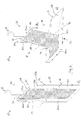
- Figure 1 shows an embodiment of a hanging pocket 10 as a conveyed goods container for transporting conveyed goods in a hanging conveyor device not shown in any further detail in the figures.
- the hanging pocket 10 comprises a first pocket side wall 12, in the present case in the form of a dimensionally stable tray, and a second pocket side wall 14, here made of an elastic textile material, which opposite one another has a conveyed goods receiving area 16 (cf. Figure 1b ) delimit between them and are connected to one another in a hinged connection area 18 such that they can be opened and closed to open and close the conveyed goods receiving area 16.
- Figure 1a shows the hanging bag 10 in a transport position in which the first bag side wall 12 and the second bag side wall 14 are folded up and hang down essentially vertically
- Figure 1b shows the hanging bag 10 in a loading position in which the first and second bag side walls 12, 14 are unfolded and an article can be inserted into or removed from the conveyed goods receiving area 16.
- loading should always include both loading and unloading.
- the hanging bag 10 of the hanging conveyor device comprises a hanging means 20 for hanging the hanging bag 10 on a guide rail arrangement (not shown here) of a hanging conveyor device.
- the attachment means 20 can, as in the illustrated embodiment, be designed as a U-shaped bracket 24 provided with a hook 22, which grasps two parallel legs 24s, which are connected to one another by an essentially horizontally extending middle part 24m.
- a conventional (mini) trolley for example, can be used.
- the attachment means comprises a joint, which enables a rotation of the hanging pocket attached to the guide rail arrangement about a vertical axis (approximately by up to 90 °), or the attachment means can be torsion-resistant to this extent.
- a hanging device 23 can be provided on the hanging means 20, for example in the form of a slot or in the form of an asymmetrically protruding eye, for example in order to be able to attach clothes hangers to the hanging means for articles that do not fit into the hanging pocket 10 due to their size or nature and are to be transported hanging. It can also be provided that the contours of the front surface in the transport direction and the rear surface of the attachment means in the transport direction are at least partially, preferably completely complementary to one another, so that adjacent hanging pockets can be "stacked" one inside the other, especially when empty and in the transport position, and stowed in little space can be, with complementary contours stabilizing each other.
- the attachment means 20 is connected to a rigid edge contour area 12r of the first pocket side wall 12 so as to be pivotable about a pivot axis 26.
- the first pocket side wall 12 is designed as a dimensionally stable tray, with a base 12b and one of these on three of four sides of the base 12b substantially perpendicularly protruding side wall 12w, which forms the rigid edge contour area 12r.
- the second pocket side wall 14 is connected at one end to the attachment means 20, more precisely to the central part 24m of the bracket 24, so that by pivoting the first pocket side wall 12 about the pivot axis 26 the first and second bag side walls 12, 14 are folded apart and together.
- the exemplary embodiment of the hanging bag 10 of the hanging conveyor according to the invention shown in the figures comprises a base assembly 50, which includes the hanging means 20 and the first bag side wall 12, and an interchangeable element 60, which includes at least part of the second bag side wall 14, in this case the entire bag side wall 14 and is interchangeably provided on the base assembly 50.
- Figure 2 shows the basic assembly 50 of the hanging bag 10 of the hanging conveyor according to the invention without the change element 60 in the transport position (a) and the loading position (b).
- the corresponding clamping bracket 70 is isolated in Figure 3 shown. It is made of, for example, a metal wire and has 4 engagement projections 70v which are arranged to fit into the openings 12o of the tray of the first bag side wall 12 when the clamping bracket 70, as in FIG Figure 4 shown, is mounted on the base assembly 50.
- the two outwardly bent ends 70e of the clamping bracket 70 can be inserted into an opening in the area of the hinge connection between the attachment means 20 and the first pocket side wall 12.
- the interchangeable element 60 is designed as a pocket made of an elastic textile or plastic material and is in Figure 5 shown in a front view (a) and a rear view (b). The different sides of the textile or plastic material are illustrated by different hatching.
- the interchangeable element 60 is made from a layer of a textile or plastic material, which has been turned over at one end and connected at the side edges 60r to form a pocket section 60t form, which extends over part of the longitudinal extension of the interchangeable element 60.
- This pocket 60t is used to hold small parts and / or to securely fix the interchangeable element 60 on the basic assembly 50.
- the pocket section 60t is followed by a flap section 60k which, in the assembled state, forms the second pocket side wall 14 of the hanging pocket 10.
- a flap section 60k which, in the assembled state, forms the second pocket side wall 14 of the hanging pocket 10.
- two clamps 28 are provided for fastening this longitudinal end to the central part 24m of the bracket 24.
- openings 60o can be provided on the side edge 60r of the pocket section 60t, the positions of which correspond to the positions of the openings 12o in the edge region of the first pocket side wall 12, and through which, as in FIG Figure 5b ) shown, the clamping bracket 70 can be inserted through it.
- the position of the upper edge 60or of the pocket section 60t of the interchangeable element 60 can correspond to a kink 70k of the clamping bracket 70, the position of which in the assembled state corresponds to the hinged connection area 18 of the hanging pocket.
- the clamping bracket 70 is now first inserted into the pocket section 60t of the interchangeable element 60, as in FIG Figure 5b ), and then the clamping bracket 70 is mounted together with the interchangeable element 60 on the base assembly 50 so that the projections 70v engage in the openings 12o, and the clamps 28 are attached to the central part 24m of the bracket 24 as attachment means 20, so the interchangeable element 60 is fixed to the base assembly 50 in an exchangeable manner, whereby the in Figure 1 illustrated embodiment of a hanging pocket 10 according to the invention results.
- different interchangeable elements can be used which differ in the material and / or in the size of the pocket side wall and / or the elasticity of the material used in order to enable flexible adaptation to different types of articles as conveyed goods.
- a basic assembly of the same type can be used for a plurality or for all hanging pockets, which reduces the costs of a hanging pocket system and also simplifies the operation of the corresponding hanging conveyor device.
- each can be provided with an identifier, in particular with a barcode or RFID transponder, which can preferably be read by corresponding reading devices of the overhead conveyor.
- matching hanging bags can be brought up to the relevant goods in association with certain groups of goods or can also be stored in their vicinity, so that the hanging bags are pre-sorted with regard to the goods to be transported therein.
Landscapes
- Engineering & Computer Science (AREA)
- Mechanical Engineering (AREA)
- Bag Frames (AREA)
- Chain Conveyers (AREA)
Description
- Die vorliegende Erfindung betrifft eine Hängefördereinrichtung, umfassend eine Führungsschienenanordnung und ein Hängetaschen-System, umfassend wenigstens zwei, vorzugsweise eine Vielzahl von bewegbar an der Führungsschienenanordnung geführten Hängetaschen als Fördergutbehälter zum Transport von Fördergut in einer Hängefördereinrichtung, mit einer ersten Taschenseitenwand und einer zweiten Taschenseitenwand, die einander gegenüberliegend einen Fördergutaufnahmebereich zwischen sich begrenzen und in einem Klappverbindungsbereich so miteinander verbunden sind, dass sie zum Öffnen und Schließen des Fördergutaufnahmebereiches auseinanderklappbar und zusammenklappbar sind, und mit einem Anhängmittel zum Anhängen der Hängetasche an eine Führungsschienenanordnung einer Hängefördereinrichtung. Dabei weist die erste Taschenseitenwand zumindest einen starren Randkontur-Bereich auf und ist daran um eine Schwenkachse schwenkbeweglich mit dem Anhängmittel verbunden, und die zweite Taschenseitenwand ist derart mit dem Anhängmittel verbunden oder davon beaufschlagbar, dass durch Schwenken der ersten Taschenseitenwand um die Schwenkachse die erste und die zweite Taschenseitenwand auseinanderklappbar und zusammenklappbar sind.
- Derartige Hängetaschen sind beispielsweise aus der
WO 2014/012965 A1 bekannt. Die Hängetaschen sind so gestaltet, dass sie aus einer Transportstellung, in welcher der Fördergutaufnahmebereich weitgehend geschlossen ist und die beiden Taschenseitenwände im Wesentlichen vertikal nach unten hängen, an einer Ladestation geöffnet werden kann, gegebenenfalls unter Verbleib an der Hängefördereinrichtung, und zwar durch Schwenken der ersten Taschenseitenwand aus ihrer vertikalen Stellung heraus um die vorzugsweise horizontale Schwenkachse. Dabei kann die erste Taschenseitenwand in eine zumindest annähernd horizontale Lage gebracht werden DieWO 2014/012965 A1 offenbart eine Hängefördereinrichtung mit den Merkmalen des Oberbegriffs des Anspruchs 1. - Bei dieser Schwenkbewegung der ersten Taschenseitenwand kommt es zu einem automatischen Aufklappen der Hängetasche, da die zweite Taschenseitenwand von dem vorzugsweise an der Hängefördereinrichtung hängenden und nach oben gerichteten Anhängmittel so beaufschlagt oder mit diesem verbunden ist, dass sie der Schwenkbewegung der ersten Taschenseitenwand nicht in einem relevanten Maße folgen kann.
- In automatisierten Warenlagern, Produktionsstätten und beim Warentransport ganz allgemein besteht häufig die Notwendigkeit, als Fördergut verschiedenartige Artikel, die sich in Gestalt, Material oder Größe erheblich unterscheiden können, zu transportieren und beispielsweise in einem Kommissionierungsverfahren zu einem Auftrag oder einer Bestellung zusammenzustellen.
- Vor dem Hintergrund dieses Standes der Technik besteht die Aufgabe der vorliegenden Erfindung darin, die bekannte Hängetasche so weiter zu entwickeln, dass sie in flexibler Weise an verschiedenartige Artikel als Fördergut angepasst werden kann.
- Diese Aufgabe wird gelöst durch eine Hängefördereinrichtung nach Anspruch 1. Bevorzugte Ausführungsformen sind Gegenstand der abhängigen Ansprüche.
- Erfindungsgemäß ist zur Lösung dieser Aufgabe vorgesehen, welche nur in Kombination mit dem beginnend auf Seite 6 beschriebenen Hängetaschen-System und als Teil einer beginnend auf Seite 7 beschriebenen Hängefördereinrichtung vorgeschlagen wird, dass die vorgenannte Hängetasche eine Basis-Baugruppe und ein Wechselelement umfasst oder daraus gebildet ist, wobei die Basis-Baugruppe das Anhängmittel und den starren Randkontur-Bereich aufweist oder daraus gebildet ist, und das Wechselelement wenigstens einen Teil der zweiten Taschenseitenwand, vorzugsweise die gesamte zweite Taschenseitenwand umfasst oder daraus gebildet ist und auswechselbar an der Basis-Baugruppe vorgesehen ist.
- Durch den zweiteiligen Aufbau der Hängetasche der erfindungsgemäßen Hängefördereinrichtung aus der Basis-Baugruppe und dem auswechselbaren Wechselelement, kann die Hängetasche durch Verwendung verschiedenartiger Wechselelemente auf einfache Weise an verschiedenartige Artikel als Fördergut angepasst werden. Durch geeignete Auswahl etwa eines weichen oder polsternden Materials für das Wechselelement können Hängetaschen zusammengestellt werden, die sich beispielsweise zur Aufnahme besonders hochwertiger oder kratzempfindlicher Artikel eignen.
- Auch können Wechselelemente verschiedener Größe oder Elastizität verwendet werden, um Hängetaschen mit verschiedenen Volumina für Artikel unterschiedlicher Größe zu erzeugen.
- Ein weiterer Vorteil der Hängetasche der erfindungsgemäßen Hängefördereinrichtung besteht darin, dass das Wechselelement wie auch die Basis-Baugruppe auf diese Weise leichter zu reinigen ist. Die Wechselelemente können beispielsweise abgenommen und separat, vorzugsweise maschinell gewaschen werden, insbesondere bei Ausbildung aus einem maschinenwaschbaren Textil-Material.
- Unter der Auswechselbarkeit des Wechselelements soll vorzugsweise verstanden werden, dass ein Wechselelement an der Basis-Baugruppe angebracht und auch wieder von dieser abgelöst werden kann, ohne die Basis-Baugruppe dabei in relevanter Weise zu beschädigen.
- Grundsätzlich ist nicht ausgeschlossen, ein Einweg-Wechselelement einzusetzen, das nach einem einmaligen Gebrauch von der Basis-Baugruppe beispielsweise durch Abreißen getrennt und dann entsorgt werden kann, insbesondere bei der Verwendung für starke schmutzende Artikel als Fördergut. Aus Gründen der Kostenreduktion und des Umweltschutzes wird jedoch bevorzugt, dass das Wechselelement dazu ausgebildet ist, wiederholt an der Basis-Baugruppe angebracht und von dieser abgelöst zu werden, und zwar besonders bevorzugt, ohne dabei wesentliche Beschädigungen zu erleiden und auch ohne Beschädigungen an der Basis-Baugruppe zu verursachen.
- Der Montageaufwand und die zur Montage benötigte Zeit können reduziert werden, indem das Wechselelement so ausgebildet ist, dass es ohne Verwendung von Werkzeug wie Schraubendrehern oder Ähnlichem an der Basis-Baugruppe angebracht und von dieser abgelöst werden kann, wie nachfolgend noch genauer beschrieben wird.
- Gemäß einer bevorzugten Weiterbildung ist das Wechselelement wenigstens abschnittsweise aus einem formschlaffen Material, insbesondere Textil oder/und aus einem elastisch nachgiebigen Material, vorzugsweise aus Kunststoff, beispielsweise einer elastischen Kunststoff-Folie, ausgebildet.
- Hierdurch kann sich das Wechselelement an unterschiedlich große Artikel als Fördergut anpassen und diese in der geschlossenen Stellung der Hängetasche gegen die erste Taschenseitenwand andrücken und auf diese Weise zumindest in gewissem Maße fixieren.
- Auch die Ausbildung des Wechselelements als wenigstens teilweise formstabiles Element, etwa eines auswechselbar an der Basis-Baugruppe montierten stabilen Rahmens mit einer vorzugsweise elastischen Textil- oder Folien-Bespannung, oder auch als vollständig formstabiles Element, etwa als auswechselbar montierter Deckel oder Haube, soll nicht ausgeschlossen sein.
- Um das Wechselelement leichter an der Basis-Baugruppe anbringen zu können oder/und das Fördergut besonders gut vor äußeren Einflüssen zu schützen oder besonders sicher aufzunehmen, kann vorgesehen sein, dass das Wechselelement als höchstens auf zwei Seiten offene Hülle oder höchstens auf einer Seite offene Tasche ausgebildet ist. Das Wechselelement kann also als eine Art "Rucksack" ausgebildet sein, der auswechselbar an der Basis-Baugruppe als Tragegestell vorgesehen ist.
- Eine besonders einfache und weitgehend werkzeugfreie Montage des Wechselelements an der Basis-Baugruppe kann dadurch erreicht werden, dass das Wechselelement vermittels einer Klemm- oder Klipsverbindung auswechselbar an der Basis-Baugruppe vorgesehen ist, beispielsweise vermittels eines Klemmbügels. Hier bieten sich für den Fachmann zahlreiche Variationen an, beispielsweise Druckknöpfe, Reiß- oder Klettverschlüsse oder Ähnliches. Auch aufwendigere, lösbare Verbindungen wie Schraubverbindungen und lösbare Schweiß- oder Fügeverbindungen sollen grundsätzlich nicht ausgeschlossen sein. Beispielsweise können thermische Verbindungen durch erneutes Erwärmen unter Umständen wieder gelöst werden.
- Gemäß einer bevorzugten Weiterbildung ist vorgesehen, dass die erste Taschenseitenwand ein Tablett umfasst und an dem Tablett schwenkbeweglich mit dem Anhängmittel verbunden ist, wobei das Wechselelement auswechselbar an dem Tablett vorgesehen ist. Das Tablett kann hierbei unterschiedliche Formen (rechteckig, rund, oval etc.) aufweisen und beispielsweise aus Hartkunststoff oder einem anderen formstabilen Material ausgebildet sein, zum Beispiel in Tiefzieh-Technik. Hierdurch wird die Stabilität der Hängetaschen erhöht. Auch ist ein vorzugsweise beschichtetes Kartonmaterial möglich, dessen Stabilität beispielsweise durch eine wabenartige Struktur erhöht sein kann.
- Insbesondere zur Aufnahme von Kleinteilen kann vorgesehen sein, dass an dem Wechselelement wenigstens eine Tasche oder ein Trennelement zur Unterteilung des Fördergutaufnahmebereiches in mehrere Teilbereiche vorgesehen ist.
- Es kann vorgesehen sein, dass das Anhängmittel der vorstehend beschriebenen Hängetaschen eine Einhängeinrichtung zum Einhängen von beispielsweise Kleiderbügeln aufweist, etwa in Form einer Einhängöffnung oder eines geeigneten Hakens, so dass auch Hängegut an den Hängetaschen aufgenommen und zusammen mit diesen transportiert werden kann.
- Die vorliegende Erfindung betrifft ein Hängetaschen-System mit wenigstens zwei, vorzugsweise einer Vielzahl von erfindungsgemäßen Hängetaschen, wie sie zuvor beschrieben wurden, wobei das Hängetaschen-System Teil der erfindungsgemäßen Hängefördereinrichtung ist, wie beginnend auf Seite 7 näher beschrieben.
- Zur Lösung der vorstehend erwähnten Aufgabe ist hierbei erfindungsgemäß vorgesehen, dass die Hängetaschen sich in wenigstens einem aus Größe, Gestalt und Material der zweiten Taschenseitenwand bzw. des Wechselelements unterscheiden, wobei wenigstens die Randkontur-Bereiche und die Anhängmittel, vorzugsweise die Basis-Baugruppen für die wenigstens zwei Hängetaschen gleichartig sind, vorzugsweise für eine Vielzahl oder für alle Hängetaschen des Hängetaschen-Systems.
- Ein derartiges Hängetaschen-System ermöglicht eine flexible Anpassung an verschiedenartige Artikel oder Warengruppen als Fördergut und erlaubt eine erhebliche Reduzierung der Kosten durch die gleichen Randkontur-Bereiche und Anhängmittel.
- Bei diesem Aspekt der Zuordnung von individualisierten Hängetaschen an bestimmte Warengruppen kommt es nicht unbedingt auf die Auswechselbarkeit eines Wechselelements an. In diesem Fall kann die zweite Taschenseitenwand auch dauerhaft und unlösbar mit der ersten Taschenseitenwand oder/und dem Anhängmittel verbunden sein. Durch Aufbauen der Hängetaschen jeweils aus einer Basis-Baugruppe und einem daran auswechselbar vorgesehenen Wechselelement können jedoch die Kosten des Systems erheblich reduziert werden.
- Insbesondere in großen Warenlagern, in welchen verschiedenartige Aufträge zusammengestellt werden und entsprechend eine Vielzahl unterschiedlicher Typen von Hängetaschen zum Einsatz kommen, kann vorzugsweise vorgesehen sein, dass die zweiten Taschenseitenwände oder die Wechselelemente jeweils mit einer vorzugsweise automatisch auslesbaren Kennung versehen sind, beispielsweise in der Form eines Strichcodes, eines 2D-Codes oder eines RFID-Transponders. Insbesondere bei Verwendung verschiedenartiger Basis-Baugruppen in einem System kann es vorteilhaft sein, zusätzlich auch die Basis-Baugruppen mit entsprechenden Kennungen zu versehen.
- Derartige Kennungen erleichtern die automatisierte Auswahl bzw. das Zusammenstellen von Hängetaschen für bestimmte Artikel.
- Schutz beansprucht wird für eine Hängefördereinrichtung, umfassend das Hängetaschen-System mit mindestens zwei erfindungsgemäßen Hängetaschen, eine Führungsschienenanordnung, an der die Hängetaschen geführt bewegbar sind, und separate Lager für die Basis-Baugruppen und die verschiedenen Wechselelemente.
- Hierbei umfasst die Hängefördereinrichtung erfindungsgemäß separate Lager für die Basis-Baugruppen und die verschiedenen Wechselelemente und wenigstens eine Station zur manuellen oder wenigstens teilweise, vorzugsweise vollständig automatisierten Zusammenstellung von Hängetaschen, die dazu eingerichtet ist, jede Hängetasche aus jeweils einer Basis-Baugruppe und einem ausgewählten Wechselelement zusammenzustellen.
- Im Betrieb solch einer Hängefördereinrichtung können die Hängetaschen oder deren Bestandteile in Zuordnung zu bestimmten Warengruppen zu den betreffenden Waren herangeführt werden, so dass insoweit schon eine Vorsortierung der Hängetaschen in Abbildung auf die von ihnen zu transportierenden Waren erfolgen kann.
- Nachfolgend wird die vorliegende Erfindung anhand eines bevorzugten Ausführungsbeispiels einer Hängetasche erläutert, die in den beiliegenden
Figuren 1 bis 5 dargestellt ist. Dabei zeigt: -
Fig. 1 in den Teilabbildungen 5a) und 5b) das Ausführungsbeispiel der Hängetasche der erfindungsgemäßen Hängefördereinrichtung in einer Transportstellung (a) und in einer Ladestellung (b). -
Fig. 2 zeigt in den Teilabbildungen 2a) und 2b) die Basis-Baugruppe der Hängetasche ausFigur 1 in der Transportstellung (a) und der Ladestellung (b). -
Fig. 3 zeigt einen Klemmbügel als Beispiel eines Befestigungsmittels zur auswechselbaren Befestigung des Wechselelements an der Basis-Baugruppe der Hängetasche ausFigur 1 . -
Fig. 4 zeigt den Gegenstand vonFigur 2b ) mit eingefügtem Klemmbügel ausFigur 3 , und -
Fig. 5 zeigt in den Teilabbildungen 5a) und 5b) das Wechselelement der Hängetasche ausFigur 1 in einer Vorderansicht (a) und einer Rückansicht (b), wobei in Teilabbildung 5b) der Klemmbügel ausFigur 3 in das Wechselelement eingesetzt ist. - Bei allen Figuren handelt es sich um stark vereinfachte Schemazeichnungen, die lediglich das Prinzip der Erfindung verdeutlichen sollen und insbesondere nicht maßgeblich zu verstehen sind. Um die Figuren nicht zu überfrachten, sind nicht alle Elemente in jeder Figur mit Bezugszeichen versehen, insbesondere in dem Fall mehrerer gleichartiger Elemente in einer Figur.
-
Figur 1 zeigt ein Ausführungsbeispiel einer Hängetasche 10 als Fördergutbehälter zum Transport von Fördergut in einer in den Figuren nicht weiter dargestellten Hängefördereinrichtung. - Die Hängetasche 10 umfasst eine erste Taschenseitenwand 12, vorliegend in Form eines formstabilen Tabletts, und eine zweite Taschenseitenwand 14, hier aus einem elastischen Textil-Material, die einander gegenüberliegend einen Fördergutaufnahmebereich 16 (vgl.
Fig. 1b ) zwischen sich begrenzen und in einem Klappverbindungsbereich 18 so miteinander verbunden sind, dass sie zum Öffnen und Schließen des Fördergutaufnahmebereiches 16 auseinander- und zusammenklappbar sind. -
Figur 1a ) zeigt die Hängetasche 10 in einer Transportstellung, in welcher die erste Taschenseitenwand 12 und die zweite Taschenseitenwand 14 zusammengeklappt sind und im Wesentlichen vertikal herabhängen, undFigur 1b ) zeigt die Hängetasche 10 in einer Ladestellung, in welcher die erste und die zweite Taschenseitenwand 12, 14 auseinandergeklappt sind, und ein Artikel in den Fördergutaufnahmebereich 16 eingelegt oder aus diesem entnommen werden kann. Der Begriff "Laden" soll hier stets sowohl das Beladen wie auch das Entladen beinhalten. - Weiterhin umfasst die Hängetasche 10 der erfindungsgemäßen Hängefördereinrichtung ein Anhängmittel 20 zum Anhängen der Hängetasche 10 an eine hier nicht weiter dargestellte Führungsschienenanordnung einer Hängefördereinrichtung.
- Das Anhängmittel 20 kann, wie in dem dargestellten Ausführungsbeispiel, als mit einem Haken 22 versehener, U-förmiger Bügel 24 ausgebildet sein, der zwei parallele Schenkel 24s, erfasst, die durch ein im Wesentlichen horizontal verlaufendes Mittelteil 24m miteinander verbunden sind. Anstelle des Hakens 22, der hier nur als einfaches Beispiel illustriert ist, kann etwa ein üblicher (Mini-)Trolley eingesetzt werden. Insbesondere kann vorgesehen sein, dass das Anhängmittel ein Gelenk umfasst, welches es eine Drehung der an der Führungsschienenanordnung angehängten Hängetasche um eine vertikale Achse (etwa um bis zu 90°) ermöglicht, oder das Anhängmittel kann insoweit auf Torsion belastbar sein.
- An dem Anhängmittel 20 kann eine Einhängvorrichtung 23 zum Beispiel in Form eines Schlitzes oder in Form eines asymmetrisch vorstehenden Auges vorgesehen sein, etwa um Kleiderbügel an dem Anhängmittel anbringen zu können, für Artikel, die aufgrund ihrer Größe oder Beschaffenheit nicht in die Hängetasche 10 hinein passen und hängend transportiert werden sollen. Auch kann vorgesehen sein, die Konturen der in Transportrichtung vorderen Fläche und der in Transportrichtung hinteren Fläche des Anhängmittels wenigstens abschnittsweise, vorzugsweise vollständig komplementär zueinander auszubilden, so dass benachbarte Hängetaschen insbesondere im Leerzustand und in der Transportstellung ineinander "stapelbar" sind und auf wenig Platz gestaut werden können, wobei komplementären Konturen sich gegenseitig stabilisieren.
- Das Anhängmittel 20 ist um eine Schwenkachse 26 schwenkbar mit einem starren Randkontur-Bereich 12r der ersten Taschenseitenwand 12 verbunden.
- In dem vorliegenden Ausführungsbeispiel ist die erste Taschenseitenwand 12 als formstabiles Tablett ausgebildet, mit einem Boden 12b und einer davon auf drei von vier Seiten des Bodens 12b im Wesentlichen senkrecht abstehenden Seitenwand 12w, die den starren Randkontur-Bereich 12r bildet.
- Die zweite Taschenseitenwand 14 ist an einem Ende mit dem Anhängmittel 20, genauer mit dem Mittelteil 24m des Bügels 24 verbunden, so dass durch Schwenken der ersten Taschenseitenwand 12 um die Schwenkachse 26 die erste und die zweite Taschenseitenwand 12, 14 auseinander-und zusammengeklappt werden.
- Zur auswechselbarem Befestigung der zweiten Taschenseitenwand 14 an dem Bügel 24 können beispielsweise zwei hier nur schematisch angedeutete Klemmen 28 als Befestigungsmittel vorgesehen sein.
- Das in den Figuren dargestellte Ausführungsbeispiel der Hängetasche 10 der erfindungsgemäßen Hängefördereinrichtung umfasst eine Basis-Baugruppe 50, die das Anhängmittel 20 und die erste Taschenseitenwand 12 umfasst, und ein Wechselelement 60, welches wenigstens einen Teil der zweiten Taschenseitenwand 14, vorliegend die gesamte Taschenseitenwand 14 umfasst und auswechselbar an der Basis-Baugruppe 50 vorgesehen ist.
-
Figur 2 stellt die Basis-Baugruppe 50 der Hängetasche 10 der erfindungsgemäßen Hängefördereinrichtung ohne das Wechselelement 60 in der Transportstellung (a) und der Ladestellung (b) dar. - Hierbei ist deutlich zu erkennen, dass in dem Bereich der Kante, in welchem der Boden 12b und die Seitenwand 12w der ersten Taschenseitenwand 12 aneinander stoßen, vier Öffnungen 12o vorgesehen sind, durch ein später noch zu beschreibender Klemmbügel 70 als Befestigungsmittel hindurch gesteckt werden kann, um das Wechselelement 60 auswechselbar an der Basis-Baugruppe 50 zu fixieren.
- Der entsprechende Klemmbügel 70 ist isoliert in
Figur 3 dargestellt. Er ist beispielsweise aus einem Metalldraht hergestellt und weist 4 Eingriffsvorsprünge 70v auf, die so angeordnet sind, dass sie in die Öffnungen 12o von dem Tablett der ersten Taschenseitenwand 12 hinein passen, wenn der Klemmbügel 70, wie inFigur 4 dargestellt, an der Basis-Baugruppe 50 montiert wird. - Die zwei nach außen abgebogenen Enden 70e des Klemmbügels 70 können dabei in eine Öffnung im Bereich der Gelenk-Verbindung zwischen dem Anhängmittel 20 und der ersten Taschenseitenwand 12 eingesteckt werden.
- Im vorliegenden Ausführungsbeispiel ist das Wechselelement 60 ausgebildet als eine Tasche aus einem elastischen Textil- oder Kunststoff-Material und ist in
Figur 5 in einer Vorderansicht (a) und einer Rückansicht (b) dargestellt. Die unterschiedlichen Seiten des Textil- bzw. Kunststoff-Materials sind dabei durch unterschiedliche Schraffuren veranschaulicht. - Wie aus einem Vergleich der Teilabbildungen 5a) und 5b) hervorgeht, ist im vorliegenden Beispiel das Wechselelement 60 aus einer Lage von einem Textil- oder Kunststoffmaterial hergestellt, welches an einem Ende umgeschlagen und an den seitlichen Rändern 60r verbunden wurde, um einen Taschenabschnitt 60t zu bilden, der sich über einen Teil von der Längserstreckung der Wechselelements 60 erstreckt. Diese Tasche 60t dient zur Aufnahme von Kleinteilen oder/und dazu, das Wechselelement 60 sicher an der Basis-Baugruppe 50 zu fixieren.
- An den Taschenabschnitt 60t schließt sich ein Klappenabschnitt 60k an, der im zusammengebauten Zustand die zweite Taschenseitenwand 14 der Hängetasche 10 bildet. An dem dem Taschenabschnitt 60t gegenüberliegenden Längsende des Wechselelements 60 sind zwei Klemmen 28 zum Befestigen dieses Längsendes an dem Mittelteil 24m des Bügels 24 vorgesehen.
- Am seitlichen Rand 60r des Taschenabschnitts 60t können vier Öffnungen 60o vorgesehen sein, deren Positionen den Positionen der Öffnungen 12o in dem Randbereich von der ersten Taschenseitenwand 12 entsprechen, und durch die, wie in
Figur 5b ) gezeigt, der Klemmbügel 70 hindurch gesteckt werden kann. - Die Position des oberen Randes 60or von dem Taschenabschnitt 60t des Wechselelements 60 kann einer Knickstelle 70k von dem Klemmbügel 70 entsprechen, dessen Position im zusammengebauten Zustand dem Klappverbindungsbereich 18 der Hängetasche entspricht.
- Wird nun zunächst der Klemmbügel 70 in den Taschenabschnitt 60t von dem Wechselelement 60 eingesetzt, wie in
Figur 5b ) gezeigt, und dann der Klemmbügel 70 zusammen mit dem Wechselelement 60 an der Basis-Baugruppe 50 montiert, so dass die Vorsprünge 70v in die Öffnungen 12o eingreifen, und werden die Klemmen 28 an dem Mittelteil 24m von dem Bügel 24 als Anhängmittel 20 angebracht, so wird das Wechselelement 60 auswechselbar an der Basis-Baugruppe 50 fixiert, wodurch sich das inFigur 1 dargestellte Ausführungsbeispiel einer erfindungsgemäßen Hängetasche 10 ergibt. - Bei dem dargestellten Ausführungsbeispiel können verschiedene Wechselelemente eingesetzt werden, die sich im Material oder/und in der Größe der Taschenseitenwand oder/und der Elastizität des verwendeten Materials unterscheiden, um eine flexible Anpassung an verschiedenartige Artikel als Fördergut zu ermöglichen.
- Für eine Mehrzahl oder für alle Hängetaschen kann dabei eine gleichartige Basis-Baugruppe verwendet werden, was die Kosten eines Hängetaschen-Systems reduziert und auch den Betrieb der entsprechenden Hängefördereinrichtung vereinfacht.
- Zur leichteren, insbesondere automatisierten Identifizierung und Auswahl der Wechselelemente können diese (in den Figuren nicht dargestellt) jeweils mit einer Kennung versehen sein, insbesondere mit einem Barcode oder RFID-Transponder, die vorzugsweise von entsprechenden Lese-Einrichtungen der Hängefördereinrichtung ausgelesen werden kann.
- Insbesondere können in einer solchen Hängefördereinrichtung passende Hängetaschen in Zuordnung zu bestimmten Warengruppen zu den betreffenden Waren herangeführt werden oder auch in deren Nähe gelagert werden, so dass insoweit schon eine Vorsortierung der Hängetaschen im Hinblick auf die darin zu transportierenden Waren stattfindet.
Claims (9)
- Hängefördereinrichtung, umfassend eine Führungsschienenanordnung und ein Hängetaschen-System, umfassend wenigstens zwei, vorzugsweise eine Vielzahl von bewegbar an der Führungsschienenanordnung geführten Hängetaschen (10) als Fördergutbehälter zum Transport von Fördergut in einer Hängefördereinrichtung, mit einer ersten Taschenseitenwand (12) und einer zweiten Taschenseitenwand (14), die einander gegenüberliegend einen Fördergutaufnahmebereich (16) zwischen sich begrenzen und in einem Klappverbindungsbereich (18) so miteinander verbunden sind, dass sie zum Öffnen und Schließen des Fördergutaufnahmebereiches (16) auseinanderklappbar und zusammenklappbar sind, und mit einem Anhängmittel (20) zum Anhängen der Hängetasche (10) an eine Führungsschienenanordnung einer Hängefördereinrichtung, wobei die erste Taschenseitenwand (12) einen starren Randkonturbereich (12r) aufweist und daran um eine Schwenkachse (26) schwenkbeweglich mit dem Anhängmittel (20) verbunden ist und wobei die zweite Taschenseitenwand (14) derart mit dem Anhängmittel (20) verbunden oder davon beaufschlagbar ist, dass durch Schwenken der ersten Taschenseitenwand (12) um die Schwenkachse (26) die erste und die zweite Taschenseitenwand (12, 14) auseinanderklappbar und zusammenklappbar sind, wobei die Hängetasche (10) eine Basis-Baugruppe (50) und ein Wechselelement (60) umfasst, wobei die Basis-Baugruppe (50) das Anhängmittel (20) und den starren Randkontur-Bereich (12r) aufweist, und das Wechselelement (60) wenigstens einen Teil der zweiten Taschenseitenwand (14), vorzugsweise die gesamte zweite Taschenseitenwand (14), umfasst und auswechselbar an der Basis-Baugruppe (50) vorgesehen ist,
dadurch gekennzeichnet, dass
die Hängetaschen (10) sich in wenigstens einem aus Größe, Gestalt und Material der zweiten Taschenseitenwand (14) oder des Wechselelements (60) unterscheiden, wobei wenigstens die Randkontur-Bereiche (12r) und die Anhängmittel (20), vorzugsweise die Basis-Baugruppen (50), für die wenigstens zwei Hängetaschen (10) gleichartig sind; und
die Hängefördereinrichtung ferner separate Lager für die Basis-Baugruppen (50) und die verschiedenen Wechselelemente (60) umfasst, wobei die Hängefördereinrichtung wenigstens eine Station zur manuellen oder wenigstens teilweise, vorzugsweise vollständig automatisierten Zusammenstellung von Hängetaschen (10) umfasst, die dazu eingerichtet ist, jede Hängetasche (10) aus jeweils einer Basis-Baugruppe (50) und einem ausgewählten Wechselelement (60) zusammenzustellen. - Hängefördereinrichtung nach Anspruch 1,
dadurch gekennzeichnet, dass das Wechselelement (60) wenigstens abschnittsweise aus einem formschlaffen Material, insbesondere Textil oder/und aus einem elastisch nachgiebigen Material, vorzugsweise aus Kunststoff, ausgebildet ist. - Hängefördereinrichtung nach einem der vorhergehenden Ansprüche,
dadurch gekennzeichnet, dass das Wechselelement (60) als höchstens auf zwei Seiten offene Hülle oder als höchstens auf einer Seite offene Tasche ausgebildet ist. - Hängefördereinrichtung nach einem der vorhergehenden Ansprüche,
dadurch gekennzeichnet, dass das Wechselelement (60) vermittels einer Klemm- oder Klips-Verbindung auswechselbar an der Basis-Baugruppe (50) vorgesehen ist, beispielsweise vermittels eines Klemmbügels (70). - Hängefördereinrichtung nach einem der vorhergehenden Ansprüche, dadurch gekennzeichnet, dass das Wechselelement (60) vermittels Druckknöpfe, Reiß- oder Klettverschlüsse auswechselbar an der Basis-Baugruppe (50) vorgesehen ist.
- Hängefördereinrichtung nach einem der vorherigen Ansprüche, dadurch gekennzeichnet, dass das Wechselelement (60) vermittels eines Klemmbügels (70) auswechselbar an der Basis-Baugruppe (50) vorgesehen ist.
- Hängefördereinrichtung nach einem der vorhergehenden Ansprüche, dadurch gekennzeichnet, dass die erste Taschenseitenwand (12) ein Tablett umfasst und an dem Tablett schwenkbeweglich mit dem Anhängmittel (20) verbunden ist, wobei das Wechselelement (60) auswechselbar an dem Tablett vorgesehen ist.
- Hängefördereinrichtung nach einem der vorhergehenden Ansprüche, dadurch gekennzeichnet, dass an dem Wechselelement (60) wenigstens eine Tasche oder ein Trennelement zur Unterteilung des Fördergutaufnahmebereiches (60) in mehrere Teilbereiche vorgesehen ist.
- Hängefördereinrichtung nach einem der vorhergehenden Ansprüche, dadurch gekennzeichnet, dass die zweiten Taschenseitenwände (14) oder die Wechselelemente (60) jeweils mit einer vorzugsweise automatisch auslesbaren Kennung versehen sind, beispielsweise in der Form eines Strichcodes, eines 2D-Codes oder eines RFID-Transponders.
Applications Claiming Priority (3)
| Application Number | Priority Date | Filing Date | Title |
|---|---|---|---|
| DE102014203299.7A DE102014203299A1 (de) | 2014-02-24 | 2014-02-24 | Hängetasche mit Wechselelement |
| EP15704555.0A EP3110726B1 (de) | 2014-02-24 | 2015-02-16 | Hängetasche mit wechselelement |
| PCT/EP2015/053204 WO2015124525A1 (de) | 2014-02-24 | 2015-02-16 | Hängetasche mit wechselelement |
Related Parent Applications (2)
| Application Number | Title | Priority Date | Filing Date |
|---|---|---|---|
| EP15704555.0A Division EP3110726B1 (de) | 2014-02-24 | 2015-02-16 | Hängetasche mit wechselelement |
| EP15704555.0A Division-Into EP3110726B1 (de) | 2014-02-24 | 2015-02-16 | Hängetasche mit wechselelement |
Publications (2)
| Publication Number | Publication Date |
|---|---|
| EP3401242A1 EP3401242A1 (de) | 2018-11-14 |
| EP3401242B1 true EP3401242B1 (de) | 2021-04-07 |
Family
ID=52472331
Family Applications (2)
| Application Number | Title | Priority Date | Filing Date |
|---|---|---|---|
| EP18180004.6A Active EP3401242B1 (de) | 2014-02-24 | 2015-02-16 | Hängefördereinrichtung |
| EP15704555.0A Not-in-force EP3110726B1 (de) | 2014-02-24 | 2015-02-16 | Hängetasche mit wechselelement |
Family Applications After (1)
| Application Number | Title | Priority Date | Filing Date |
|---|---|---|---|
| EP15704555.0A Not-in-force EP3110726B1 (de) | 2014-02-24 | 2015-02-16 | Hängetasche mit wechselelement |
Country Status (5)
| Country | Link |
|---|---|
| US (1) | US9828182B2 (de) |
| EP (2) | EP3401242B1 (de) |
| DE (1) | DE102014203299A1 (de) |
| ES (1) | ES2786308T3 (de) |
| WO (1) | WO2015124525A1 (de) |
Families Citing this family (12)
| Publication number | Priority date | Publication date | Assignee | Title |
|---|---|---|---|---|
| DE202014010433U1 (de) * | 2014-07-02 | 2015-07-27 | Meri Environmental Solutions Gmbh | Förderanlage zum Fördern von Fördergut |
| CH710650A1 (de) * | 2015-01-26 | 2016-07-29 | Ferag Ag | Transportvorrichtung, insbesondere in Form eines Hängeförderers. |
| CH711565A1 (de) * | 2015-09-24 | 2017-03-31 | Ferag Ag | Transporttasche für den Transport und/oder die Aufbewahrung von Gegenständen sowie Transportvorrichtung mit einer solchen Transporttasche. |
| WO2018015885A1 (en) * | 2016-07-20 | 2018-01-25 | Dematic Corp | Order fulfillment method and system with sortation at induct background of the invention |
| CH712895A1 (de) | 2016-09-09 | 2018-03-15 | Ferag Ag | Verfahren zum Öffnen einer an einem Laufwagen hängenden Transporttasche sowie Taschenöffnungsvorrichtung zur Durchführung des Verfahrens. |
| CN109791651A (zh) * | 2016-11-08 | 2019-05-21 | Rsl物流有限公司 | 用于零部件物流的方法和设备 |
| DE202017100206U1 (de) | 2017-01-16 | 2018-04-17 | Tgw Mechanics Gmbh | Fördergutbehälter mit Auswerfvorrichtung und zugehörige Hängefördervorrichtung |
| EP3810530B2 (de) | 2018-06-21 | 2026-03-18 | TGW Logistics GmbH | Lager- und kommissioniersystem sowie verfahren zum kommissionieren von auftragswaren aus einer hängetasche und einem anderen ladehilfsmittel |
| CA3104334A1 (en) | 2018-06-21 | 2019-12-26 | Tgw Logistics Group Gmbh | Storage and order-picking system as well as order-picking method with improved transfer of goods between two storage zones |
| DE112019003084A5 (de) | 2018-06-21 | 2021-04-15 | Tgw Logistics Group Gmbh | Lager- und kommissioniersystem sowie kommissionierverfahren mit verbessertem warentransfer zwischen zwei lagerbereichen |
| EP3826943B1 (de) | 2018-07-23 | 2022-06-08 | TGW Logistics Group GmbH | Lager- und kommissioniersystem mit verkürzter durchlaufzeit und verfahren zum betrieb desselben |
| US12275593B2 (en) * | 2022-03-11 | 2025-04-15 | Jack Pearson | Payload transport carrier |
Family Cites Families (24)
| Publication number | Priority date | Publication date | Assignee | Title |
|---|---|---|---|---|
| US3778972A (en) * | 1972-03-28 | 1973-12-18 | A Chlipalski | Apparatus for handling liquid filled flexible pouches |
| DE2940266A1 (de) * | 1979-10-04 | 1981-06-11 | Greiff-Werke Gustav Winkler Bamberg GmbH & Co, 8600 Bamberg | Trolley |
| DE8516343U1 (de) * | 1985-06-04 | 1987-07-16 | Gärtner, Franz, 8741 Unterelsbach | Fördervorrichtung |
| SE464245B (sv) * | 1987-07-13 | 1991-03-25 | Pronova Ab | Foerpackningsband |
| US4873812A (en) * | 1987-09-10 | 1989-10-17 | Wilfreid Pavel Machinenbau | Clothing article packaging machine |
| DE4114283C2 (de) * | 1991-05-02 | 1994-06-16 | Duerkopp Adler Ag | Hängeförderer für auf Bügel hängendes Transportgut |
| DE4244760C2 (de) * | 1992-07-17 | 1994-11-03 | Scholtz Conrad Gmbh | Taschenförderer |
| DE19549166A1 (de) * | 1995-12-29 | 1997-07-03 | Conteyor Multibag Sys Bv | Transportvorrichtung für Stückgut |
| US5697508A (en) * | 1996-07-24 | 1997-12-16 | A. Rifkin & Co. | Trolley and bag assembly for transporting hanger-hung garments |
| DE19914027A1 (de) * | 1999-03-27 | 2000-09-28 | Conteyor Multibag Systems Nv | Vorrichtung für die Aufbewahrung und den Transport von Stückgut |
| CA2316725C (en) * | 1999-09-01 | 2008-02-26 | Ykk Corporation | Flexible container for liquid transport, liquid transport method using the container, liquid transport apparatus using the container, method for washing the container, and washingequipment |
| US6446416B1 (en) * | 1999-11-03 | 2002-09-10 | R. A. Jones & Co. Inc. | Vertical insert bucket |
| ATE444902T1 (de) * | 2003-08-27 | 2009-10-15 | Muraharu Seisakusho Kk | Einpackvorrichtung für artikel |
| DE10354419A1 (de) * | 2003-11-21 | 2005-06-23 | Wf Logistik Gmbh | Hängefördereinrichtung zum Transportieren von Fördergut, insbesondere Kleidungsstücken |
| DE102004018569B4 (de) * | 2004-04-16 | 2016-06-09 | Psb Intralogistics Gmbh | Sammeleinrichtung zum Aufnehmen von Objekten beim sortierenden Sammeln der Objekte sowie Fördervorrichtung zum Transport von Sammeltaschen |
| US20060249514A1 (en) * | 2005-05-05 | 2006-11-09 | Bradford Company | Container having sliding support member assemblies for supporting dunnage |
| DE102008061685A1 (de) * | 2008-12-11 | 2010-06-17 | Dürkopp Adler AG | Belade-Station für in einer Hänge-Förder-Anlage transportierte Transport-Taschen |
| DE102010033905A1 (de) * | 2010-08-10 | 2012-02-16 | Dürkopp Fördertechnik GmbH | Förderanlage mit Tragetaschen für Fördergut |
| DE102010053590B4 (de) * | 2010-12-06 | 2019-03-07 | Dürkopp Fördertechnik GmbH | Tragetasche für Fördergut und Förderanlage für eine Tragetasche |
| US8490774B2 (en) * | 2011-02-24 | 2013-07-23 | Dürkopp Fördertechnik GmbH | Loading station for transport bags transported in an overhead conveyor system |
| DE102012212518B4 (de) | 2012-07-17 | 2023-12-07 | Rsl Logistik Gmbh & Co. Kg | Fördergutbehälter, Hängefördereinrichtung und Verfahren zum Transportieren |
| DE102013205172B4 (de) * | 2013-03-22 | 2018-03-22 | Dürkopp Fördertechnik GmbH | Transporttasche zum hängenden Transport von Waren, Beladestation und Förderanlage |
| CH711565A1 (de) * | 2015-09-24 | 2017-03-31 | Ferag Ag | Transporttasche für den Transport und/oder die Aufbewahrung von Gegenständen sowie Transportvorrichtung mit einer solchen Transporttasche. |
| EP3231741A1 (de) * | 2016-04-15 | 2017-10-18 | Dematic Logistics GmbH | Transporttasche, fördervorrichtung und verfahren zum öffnen bzw. schliessen einer transporttasche |
-
2014
- 2014-02-24 DE DE102014203299.7A patent/DE102014203299A1/de not_active Withdrawn
-
2015
- 2015-02-16 EP EP18180004.6A patent/EP3401242B1/de active Active
- 2015-02-16 ES ES15704555T patent/ES2786308T3/es active Active
- 2015-02-16 EP EP15704555.0A patent/EP3110726B1/de not_active Not-in-force
- 2015-02-16 US US15/121,022 patent/US9828182B2/en not_active Expired - Fee Related
- 2015-02-16 WO PCT/EP2015/053204 patent/WO2015124525A1/de not_active Ceased
Non-Patent Citations (1)
| Title |
|---|
| None * |
Also Published As
| Publication number | Publication date |
|---|---|
| US20170015505A1 (en) | 2017-01-19 |
| DE102014203299A1 (de) | 2015-08-27 |
| EP3401242A1 (de) | 2018-11-14 |
| EP3110726A1 (de) | 2017-01-04 |
| WO2015124525A1 (de) | 2015-08-27 |
| EP3110726B1 (de) | 2020-04-01 |
| US9828182B2 (en) | 2017-11-28 |
| ES2786308T3 (es) | 2020-10-09 |
Similar Documents
| Publication | Publication Date | Title |
|---|---|---|
| EP3401242B1 (de) | Hängefördereinrichtung | |
| EP3250484B1 (de) | Transportvorrichtung in form eines hängeförderers | |
| EP3147240B1 (de) | Transporttasche für den transport und/oder die aufbewahrung von gegenständen sowie transportvorrichtung mit einer solchen transporttasche | |
| EP3090967B1 (de) | Hängetasche mit trapdoor sowie hängetaschengestell zum ausbilden einer solchen sowie hängefördereinrichtung umfassend eine solche | |
| DE102014224872A1 (de) | Transporttasche zum Transportieren einer Ware in einer Hängewarenförderanlage | |
| WO2017088076A1 (de) | Transporttasche sowie verfahren zum befüllen und entleeren einer solchen transporttasche | |
| DE202017106993U1 (de) | Transporttasche zum Transportieren einer Ware in einer Hängewarenförderanlage | |
| EP2418160A1 (de) | Förderanlage mit Tragetaschen für Fördergut | |
| DE102014203298A1 (de) | Hängefördereinrichtung mit Ladestation | |
| DE3635153A1 (de) | Karton, insbesondere eierkarton | |
| DE60106536T2 (de) | Schauverpackung mit einer Hängerkarte | |
| EP1097088A1 (de) | Vorrichtung zur aufbewahrung und zum transport von stückgut | |
| EP4049946A2 (de) | Vorrichtung zum transport von an trägern hängenden textilen gegenständen, vorzugsweise bekleidungsstücken | |
| DE102009044929B4 (de) | Gefache, Transportbehälter oder Gestell sowie Verfahren zur Herstellung eines Gefaches | |
| EP3360445A1 (de) | Aufhängeverpackung sowei aufhänger für eine warenverpackung einer aufhängeverpackung | |
| EP0709051B1 (de) | Stapelbarer Kleiderbügel | |
| DE2938895C2 (de) | Vorrichtung zum Tragen einer Anzahl Bügel | |
| WO2000003925A1 (de) | Vorrichtung zur aufbewahrung und zum transport von stückgut | |
| DE9100783U1 (de) | Verkaufshilfe | |
| CH720950A1 (de) | Fördertasche für eine hängeförderanlage | |
| EP3539888B1 (de) | Einseitig offener tragekorb und verfahren zur herstellung eines einseitig offenen tragekorbs | |
| DE19831968A1 (de) | Vorrichtung für den Transport und die Aufbewahrung von Autostoßstangen | |
| DE961605C (de) | Flach auslegbare Verpackung | |
| DE2755348A1 (de) | Hinsichtlich ihres transportes zusammenlegbare kleiderhuelle | |
| DE202007013029U1 (de) | Schachtel zum Anbieten und Lagern von Ware |
Legal Events
| Date | Code | Title | Description |
|---|---|---|---|
| PUAI | Public reference made under article 153(3) epc to a published international application that has entered the european phase |
Free format text: ORIGINAL CODE: 0009012 |
|
| STAA | Information on the status of an ep patent application or granted ep patent |
Free format text: STATUS: REQUEST FOR EXAMINATION WAS MADE |
|
| 17P | Request for examination filed |
Effective date: 20180627 |
|
| AC | Divisional application: reference to earlier application |
Ref document number: 3110726 Country of ref document: EP Kind code of ref document: P |
|
| AK | Designated contracting states |
Kind code of ref document: A1 Designated state(s): AL AT BE BG CH CY CZ DE DK EE ES FI FR GB GR HR HU IE IS IT LI LT LU LV MC MK MT NL NO PL PT RO RS SE SI SK SM TR |
|
| REG | Reference to a national code |
Ref country code: DE Ref legal event code: R079 Ref document number: 502015014539 Country of ref document: DE Free format text: PREVIOUS MAIN CLASS: B65G0017200000 Ipc: B65G0017480000 |
|
| RIC1 | Information provided on ipc code assigned before grant |
Ipc: B65G 17/20 20060101ALI20200922BHEP Ipc: B65G 17/48 20060101AFI20200922BHEP |
|
| GRAP | Despatch of communication of intention to grant a patent |
Free format text: ORIGINAL CODE: EPIDOSNIGR1 |
|
| STAA | Information on the status of an ep patent application or granted ep patent |
Free format text: STATUS: GRANT OF PATENT IS INTENDED |
|
| INTG | Intention to grant announced |
Effective date: 20201116 |
|
| GRAS | Grant fee paid |
Free format text: ORIGINAL CODE: EPIDOSNIGR3 |
|
| GRAA | (expected) grant |
Free format text: ORIGINAL CODE: 0009210 |
|
| STAA | Information on the status of an ep patent application or granted ep patent |
Free format text: STATUS: THE PATENT HAS BEEN GRANTED |
|
| AC | Divisional application: reference to earlier application |
Ref document number: 3110726 Country of ref document: EP Kind code of ref document: P |
|
| AK | Designated contracting states |
Kind code of ref document: B1 Designated state(s): AL AT BE BG CH CY CZ DE DK EE ES FI FR GB GR HR HU IE IS IT LI LT LU LV MC MK MT NL NO PL PT RO RS SE SI SK SM TR |
|
| REG | Reference to a national code |
Ref country code: GB Ref legal event code: FG4D Free format text: NOT ENGLISH |
|
| REG | Reference to a national code |
Ref country code: AT Ref legal event code: REF Ref document number: 1379457 Country of ref document: AT Kind code of ref document: T Effective date: 20210415 Ref country code: CH Ref legal event code: EP |
|
| REG | Reference to a national code |
Ref country code: DE Ref legal event code: R096 Ref document number: 502015014539 Country of ref document: DE |
|
| REG | Reference to a national code |
Ref country code: IE Ref legal event code: FG4D Free format text: LANGUAGE OF EP DOCUMENT: GERMAN |
|
| REG | Reference to a national code |
Ref country code: LT Ref legal event code: MG9D |
|
| REG | Reference to a national code |
Ref country code: NL Ref legal event code: MP Effective date: 20210407 |
|
| PG25 | Lapsed in a contracting state [announced via postgrant information from national office to epo] |
Ref country code: NL Free format text: LAPSE BECAUSE OF FAILURE TO SUBMIT A TRANSLATION OF THE DESCRIPTION OR TO PAY THE FEE WITHIN THE PRESCRIBED TIME-LIMIT Effective date: 20210407 Ref country code: BG Free format text: LAPSE BECAUSE OF FAILURE TO SUBMIT A TRANSLATION OF THE DESCRIPTION OR TO PAY THE FEE WITHIN THE PRESCRIBED TIME-LIMIT Effective date: 20210707 Ref country code: LT Free format text: LAPSE BECAUSE OF FAILURE TO SUBMIT A TRANSLATION OF THE DESCRIPTION OR TO PAY THE FEE WITHIN THE PRESCRIBED TIME-LIMIT Effective date: 20210407 Ref country code: HR Free format text: LAPSE BECAUSE OF FAILURE TO SUBMIT A TRANSLATION OF THE DESCRIPTION OR TO PAY THE FEE WITHIN THE PRESCRIBED TIME-LIMIT Effective date: 20210407 Ref country code: FI Free format text: LAPSE BECAUSE OF FAILURE TO SUBMIT A TRANSLATION OF THE DESCRIPTION OR TO PAY THE FEE WITHIN THE PRESCRIBED TIME-LIMIT Effective date: 20210407 |
|
| PG25 | Lapsed in a contracting state [announced via postgrant information from national office to epo] |
Ref country code: SE Free format text: LAPSE BECAUSE OF FAILURE TO SUBMIT A TRANSLATION OF THE DESCRIPTION OR TO PAY THE FEE WITHIN THE PRESCRIBED TIME-LIMIT Effective date: 20210407 Ref country code: RS Free format text: LAPSE BECAUSE OF FAILURE TO SUBMIT A TRANSLATION OF THE DESCRIPTION OR TO PAY THE FEE WITHIN THE PRESCRIBED TIME-LIMIT Effective date: 20210407 Ref country code: NO Free format text: LAPSE BECAUSE OF FAILURE TO SUBMIT A TRANSLATION OF THE DESCRIPTION OR TO PAY THE FEE WITHIN THE PRESCRIBED TIME-LIMIT Effective date: 20210707 Ref country code: LV Free format text: LAPSE BECAUSE OF FAILURE TO SUBMIT A TRANSLATION OF THE DESCRIPTION OR TO PAY THE FEE WITHIN THE PRESCRIBED TIME-LIMIT Effective date: 20210407 Ref country code: PL Free format text: LAPSE BECAUSE OF FAILURE TO SUBMIT A TRANSLATION OF THE DESCRIPTION OR TO PAY THE FEE WITHIN THE PRESCRIBED TIME-LIMIT Effective date: 20210407 Ref country code: PT Free format text: LAPSE BECAUSE OF FAILURE TO SUBMIT A TRANSLATION OF THE DESCRIPTION OR TO PAY THE FEE WITHIN THE PRESCRIBED TIME-LIMIT Effective date: 20210809 Ref country code: IS Free format text: LAPSE BECAUSE OF FAILURE TO SUBMIT A TRANSLATION OF THE DESCRIPTION OR TO PAY THE FEE WITHIN THE PRESCRIBED TIME-LIMIT Effective date: 20210807 Ref country code: GR Free format text: LAPSE BECAUSE OF FAILURE TO SUBMIT A TRANSLATION OF THE DESCRIPTION OR TO PAY THE FEE WITHIN THE PRESCRIBED TIME-LIMIT Effective date: 20210708 |
|
| REG | Reference to a national code |
Ref country code: DE Ref legal event code: R097 Ref document number: 502015014539 Country of ref document: DE |
|
| PG25 | Lapsed in a contracting state [announced via postgrant information from national office to epo] |
Ref country code: DK Free format text: LAPSE BECAUSE OF FAILURE TO SUBMIT A TRANSLATION OF THE DESCRIPTION OR TO PAY THE FEE WITHIN THE PRESCRIBED TIME-LIMIT Effective date: 20210407 Ref country code: CZ Free format text: LAPSE BECAUSE OF FAILURE TO SUBMIT A TRANSLATION OF THE DESCRIPTION OR TO PAY THE FEE WITHIN THE PRESCRIBED TIME-LIMIT Effective date: 20210407 Ref country code: RO Free format text: LAPSE BECAUSE OF FAILURE TO SUBMIT A TRANSLATION OF THE DESCRIPTION OR TO PAY THE FEE WITHIN THE PRESCRIBED TIME-LIMIT Effective date: 20210407 Ref country code: SK Free format text: LAPSE BECAUSE OF FAILURE TO SUBMIT A TRANSLATION OF THE DESCRIPTION OR TO PAY THE FEE WITHIN THE PRESCRIBED TIME-LIMIT Effective date: 20210407 Ref country code: SM Free format text: LAPSE BECAUSE OF FAILURE TO SUBMIT A TRANSLATION OF THE DESCRIPTION OR TO PAY THE FEE WITHIN THE PRESCRIBED TIME-LIMIT Effective date: 20210407 Ref country code: ES Free format text: LAPSE BECAUSE OF FAILURE TO SUBMIT A TRANSLATION OF THE DESCRIPTION OR TO PAY THE FEE WITHIN THE PRESCRIBED TIME-LIMIT Effective date: 20210407 Ref country code: EE Free format text: LAPSE BECAUSE OF FAILURE TO SUBMIT A TRANSLATION OF THE DESCRIPTION OR TO PAY THE FEE WITHIN THE PRESCRIBED TIME-LIMIT Effective date: 20210407 |
|
| PLBE | No opposition filed within time limit |
Free format text: ORIGINAL CODE: 0009261 |
|
| STAA | Information on the status of an ep patent application or granted ep patent |
Free format text: STATUS: NO OPPOSITION FILED WITHIN TIME LIMIT |
|
| 26N | No opposition filed |
Effective date: 20220110 |
|
| PG25 | Lapsed in a contracting state [announced via postgrant information from national office to epo] |
Ref country code: IS Free format text: LAPSE BECAUSE OF FAILURE TO SUBMIT A TRANSLATION OF THE DESCRIPTION OR TO PAY THE FEE WITHIN THE PRESCRIBED TIME-LIMIT Effective date: 20210807 Ref country code: AL Free format text: LAPSE BECAUSE OF FAILURE TO SUBMIT A TRANSLATION OF THE DESCRIPTION OR TO PAY THE FEE WITHIN THE PRESCRIBED TIME-LIMIT Effective date: 20210407 |
|
| PG25 | Lapsed in a contracting state [announced via postgrant information from national office to epo] |
Ref country code: IT Free format text: LAPSE BECAUSE OF FAILURE TO SUBMIT A TRANSLATION OF THE DESCRIPTION OR TO PAY THE FEE WITHIN THE PRESCRIBED TIME-LIMIT Effective date: 20210407 |
|
| PG25 | Lapsed in a contracting state [announced via postgrant information from national office to epo] |
Ref country code: MC Free format text: LAPSE BECAUSE OF FAILURE TO SUBMIT A TRANSLATION OF THE DESCRIPTION OR TO PAY THE FEE WITHIN THE PRESCRIBED TIME-LIMIT Effective date: 20210407 |
|
| REG | Reference to a national code |
Ref country code: CH Ref legal event code: PL |
|
| REG | Reference to a national code |
Ref country code: BE Ref legal event code: MM Effective date: 20220228 |
|
| GBPC | Gb: european patent ceased through non-payment of renewal fee |
Effective date: 20220216 |
|
| PG25 | Lapsed in a contracting state [announced via postgrant information from national office to epo] |
Ref country code: LU Free format text: LAPSE BECAUSE OF NON-PAYMENT OF DUE FEES Effective date: 20220216 |
|
| PG25 | Lapsed in a contracting state [announced via postgrant information from national office to epo] |
Ref country code: IE Free format text: LAPSE BECAUSE OF NON-PAYMENT OF DUE FEES Effective date: 20220216 Ref country code: GB Free format text: LAPSE BECAUSE OF NON-PAYMENT OF DUE FEES Effective date: 20220216 Ref country code: CH Free format text: LAPSE BECAUSE OF NON-PAYMENT OF DUE FEES Effective date: 20220228 Ref country code: LI Free format text: LAPSE BECAUSE OF NON-PAYMENT OF DUE FEES Effective date: 20220228 |
|
| PG25 | Lapsed in a contracting state [announced via postgrant information from national office to epo] |
Ref country code: BE Free format text: LAPSE BECAUSE OF NON-PAYMENT OF DUE FEES Effective date: 20220228 |
|
| PG25 | Lapsed in a contracting state [announced via postgrant information from national office to epo] |
Ref country code: HU Free format text: LAPSE BECAUSE OF FAILURE TO SUBMIT A TRANSLATION OF THE DESCRIPTION OR TO PAY THE FEE WITHIN THE PRESCRIBED TIME-LIMIT; INVALID AB INITIO Effective date: 20150216 |
|
| PGFP | Annual fee paid to national office [announced via postgrant information from national office to epo] |
Ref country code: AT Payment date: 20240220 Year of fee payment: 10 |
|
| PG25 | Lapsed in a contracting state [announced via postgrant information from national office to epo] |
Ref country code: MK Free format text: LAPSE BECAUSE OF FAILURE TO SUBMIT A TRANSLATION OF THE DESCRIPTION OR TO PAY THE FEE WITHIN THE PRESCRIBED TIME-LIMIT Effective date: 20210407 Ref country code: CY Free format text: LAPSE BECAUSE OF FAILURE TO SUBMIT A TRANSLATION OF THE DESCRIPTION OR TO PAY THE FEE WITHIN THE PRESCRIBED TIME-LIMIT Effective date: 20210407 |
|
| PGFP | Annual fee paid to national office [announced via postgrant information from national office to epo] |
Ref country code: DE Payment date: 20240131 Year of fee payment: 10 |
|
| PGFP | Annual fee paid to national office [announced via postgrant information from national office to epo] |
Ref country code: FR Payment date: 20240221 Year of fee payment: 10 |
|
| PG25 | Lapsed in a contracting state [announced via postgrant information from national office to epo] |
Ref country code: TR Free format text: LAPSE BECAUSE OF FAILURE TO SUBMIT A TRANSLATION OF THE DESCRIPTION OR TO PAY THE FEE WITHIN THE PRESCRIBED TIME-LIMIT Effective date: 20210407 |
|
| PG25 | Lapsed in a contracting state [announced via postgrant information from national office to epo] |
Ref country code: MT Free format text: LAPSE BECAUSE OF FAILURE TO SUBMIT A TRANSLATION OF THE DESCRIPTION OR TO PAY THE FEE WITHIN THE PRESCRIBED TIME-LIMIT Effective date: 20210407 |
|
| REG | Reference to a national code |
Ref country code: DE Ref legal event code: R119 Ref document number: 502015014539 Country of ref document: DE |
|
| REG | Reference to a national code |
Ref country code: AT Ref legal event code: MM01 Ref document number: 1379457 Country of ref document: AT Kind code of ref document: T Effective date: 20250216 |
|
| PG25 | Lapsed in a contracting state [announced via postgrant information from national office to epo] |
Ref country code: AT Free format text: LAPSE BECAUSE OF NON-PAYMENT OF DUE FEES Effective date: 20250216 |
|
| PG25 | Lapsed in a contracting state [announced via postgrant information from national office to epo] |
Ref country code: DE Free format text: LAPSE BECAUSE OF NON-PAYMENT OF DUE FEES Effective date: 20250902 |
|
| PG25 | Lapsed in a contracting state [announced via postgrant information from national office to epo] |
Ref country code: FR Free format text: LAPSE BECAUSE OF NON-PAYMENT OF DUE FEES Effective date: 20250228 |