EP3401253B1 - Appareil pour désempiler automatiquement une palette sur lequel au moins deux piles de découpes sont disposées - Google Patents
Appareil pour désempiler automatiquement une palette sur lequel au moins deux piles de découpes sont disposées Download PDFInfo
- Publication number
- EP3401253B1 EP3401253B1 EP18171794.3A EP18171794A EP3401253B1 EP 3401253 B1 EP3401253 B1 EP 3401253B1 EP 18171794 A EP18171794 A EP 18171794A EP 3401253 B1 EP3401253 B1 EP 3401253B1
- Authority
- EP
- European Patent Office
- Prior art keywords
- blank
- blanks
- pallet
- gripper
- stacks
- Prior art date
- Legal status (The legal status is an assumption and is not a legal conclusion. Google has not performed a legal analysis and makes no representation as to the accuracy of the status listed.)
- Active
Links
Images

Classifications
-
- B—PERFORMING OPERATIONS; TRANSPORTING
- B65—CONVEYING; PACKING; STORING; HANDLING THIN OR FILAMENTARY MATERIAL
- B65H—HANDLING THIN OR FILAMENTARY MATERIAL, e.g. SHEETS, WEBS, CABLES
- B65H3/00—Separating articles from piles
- B65H3/08—Separating articles from piles using pneumatic force
- B65H3/0808—Suction grippers
- B65H3/0816—Suction grippers separating from the top of pile
-
- B—PERFORMING OPERATIONS; TRANSPORTING
- B25—HAND TOOLS; PORTABLE POWER-DRIVEN TOOLS; MANIPULATORS
- B25J—MANIPULATORS; CHAMBERS PROVIDED WITH MANIPULATION DEVICES
- B25J9/00—Program-controlled manipulators
- B25J9/02—Program-controlled manipulators characterised by movement of the arms, e.g. cartesian coordinate type
- B25J9/04—Program-controlled manipulators characterised by movement of the arms, e.g. cartesian coordinate type by rotating at least one arm, excluding the head movement itself, e.g. cylindrical coordinate type or polar coordinate type
- B25J9/041—Cylindrical coordinate type
- B25J9/042—Cylindrical coordinate type comprising an articulated arm
- B25J9/043—Cylindrical coordinate type comprising an articulated arm double selective compliance articulated robot arms [SCARA]
-
- B—PERFORMING OPERATIONS; TRANSPORTING
- B31—MAKING ARTICLES OF PAPER, CARDBOARD OR MATERIAL WORKED IN A MANNER ANALOGOUS TO PAPER; WORKING PAPER, CARDBOARD OR MATERIAL WORKED IN A MANNER ANALOGOUS TO PAPER
- B31B—MAKING CONTAINERS OF PAPER, CARDBOARD OR MATERIAL WORKED IN A MANNER ANALOGOUS TO PAPER
- B31B50/00—Making rigid or semi-rigid containers, e.g. boxes or cartons
- B31B50/02—Feeding or positioning sheets, blanks or webs
- B31B50/04—Feeding sheets or blanks
- B31B50/06—Feeding sheets or blanks from stacks
-
- B—PERFORMING OPERATIONS; TRANSPORTING
- B65—CONVEYING; PACKING; STORING; HANDLING THIN OR FILAMENTARY MATERIAL
- B65G—TRANSPORT OR STORAGE DEVICES, e.g. CONVEYORS FOR LOADING OR TIPPING, SHOP CONVEYOR SYSTEMS OR PNEUMATIC TUBE CONVEYORS
- B65G47/00—Article or material-handling devices associated with conveyors; Methods employing such devices
- B65G47/52—Devices for transferring articles or materials between conveyors i.e. discharging or feeding devices
- B65G47/64—Switching conveyors
-
- B—PERFORMING OPERATIONS; TRANSPORTING
- B65—CONVEYING; PACKING; STORING; HANDLING THIN OR FILAMENTARY MATERIAL
- B65G—TRANSPORT OR STORAGE DEVICES, e.g. CONVEYORS FOR LOADING OR TIPPING, SHOP CONVEYOR SYSTEMS OR PNEUMATIC TUBE CONVEYORS
- B65G59/00—De-stacking of articles
- B65G59/02—De-stacking from the top of the stack
- B65G59/04—De-stacking from the top of the stack by suction or magnetic devices
-
- B—PERFORMING OPERATIONS; TRANSPORTING
- B65—CONVEYING; PACKING; STORING; HANDLING THIN OR FILAMENTARY MATERIAL
- B65H—HANDLING THIN OR FILAMENTARY MATERIAL, e.g. SHEETS, WEBS, CABLES
- B65H1/00—Supports or magazines for piles from which articles are to be separated
- B65H1/08—Supports or magazines for piles from which articles are to be separated with means for advancing the articles to present the articles to the separating device
- B65H1/14—Supports or magazines for piles from which articles are to be separated with means for advancing the articles to present the articles to the separating device comprising positively-acting mechanical devices
-
- B—PERFORMING OPERATIONS; TRANSPORTING
- B65—CONVEYING; PACKING; STORING; HANDLING THIN OR FILAMENTARY MATERIAL
- B65H—HANDLING THIN OR FILAMENTARY MATERIAL, e.g. SHEETS, WEBS, CABLES
- B65H1/00—Supports or magazines for piles from which articles are to be separated
- B65H1/28—Supports or magazines for piles from which articles are to be separated compartmented to receive piles side-by-side
-
- B—PERFORMING OPERATIONS; TRANSPORTING
- B65—CONVEYING; PACKING; STORING; HANDLING THIN OR FILAMENTARY MATERIAL
- B65H—HANDLING THIN OR FILAMENTARY MATERIAL, e.g. SHEETS, WEBS, CABLES
- B65H5/00—Feeding articles separated from piles; Feeding articles to machines
- B65H5/08—Feeding articles separated from piles; Feeding articles to machines by grippers, e.g. suction grippers
-
- B—PERFORMING OPERATIONS; TRANSPORTING
- B65—CONVEYING; PACKING; STORING; HANDLING THIN OR FILAMENTARY MATERIAL
- B65H—HANDLING THIN OR FILAMENTARY MATERIAL, e.g. SHEETS, WEBS, CABLES
- B65H5/00—Feeding articles separated from piles; Feeding articles to machines
- B65H5/16—Feeding articles separated from piles; Feeding articles to machines by pusher, needles, friction, or like devices adapted to feed single articles along a surface or table
-
- B—PERFORMING OPERATIONS; TRANSPORTING
- B65—CONVEYING; PACKING; STORING; HANDLING THIN OR FILAMENTARY MATERIAL
- B65H—HANDLING THIN OR FILAMENTARY MATERIAL, e.g. SHEETS, WEBS, CABLES
- B65H2301/00—Handling processes for sheets or webs
- B65H2301/30—Orientation, displacement, position of the handled material
- B65H2301/34—Modifying, selecting, changing direction of displacement
- B65H2301/342—Modifying, selecting, changing direction of displacement with change of plane of displacement
- B65H2301/3422—Modifying, selecting, changing direction of displacement with change of plane of displacement by travelling a path section in arc of circle
-
- B—PERFORMING OPERATIONS; TRANSPORTING
- B65—CONVEYING; PACKING; STORING; HANDLING THIN OR FILAMENTARY MATERIAL
- B65H—HANDLING THIN OR FILAMENTARY MATERIAL, e.g. SHEETS, WEBS, CABLES
- B65H2301/00—Handling processes for sheets or webs
- B65H2301/40—Type of handling process
- B65H2301/42—Piling, depiling, handling piles
- B65H2301/422—Handling piles, sets or stacks of articles
- B65H2301/4225—Handling piles, sets or stacks of articles in or on special supports
- B65H2301/42256—Pallets; Skids; Platforms with feet, i.e. handled together with the stack
-
- B—PERFORMING OPERATIONS; TRANSPORTING
- B65—CONVEYING; PACKING; STORING; HANDLING THIN OR FILAMENTARY MATERIAL
- B65H—HANDLING THIN OR FILAMENTARY MATERIAL, e.g. SHEETS, WEBS, CABLES
- B65H2555/00—Actuating means
- B65H2555/30—Multi-axis
-
- B—PERFORMING OPERATIONS; TRANSPORTING
- B65—CONVEYING; PACKING; STORING; HANDLING THIN OR FILAMENTARY MATERIAL
- B65H—HANDLING THIN OR FILAMENTARY MATERIAL, e.g. SHEETS, WEBS, CABLES
- B65H2701/00—Handled material; Storage means
- B65H2701/10—Handled articles or webs
- B65H2701/17—Nature of material
- B65H2701/176—Cardboard
-
- B—PERFORMING OPERATIONS; TRANSPORTING
- B65—CONVEYING; PACKING; STORING; HANDLING THIN OR FILAMENTARY MATERIAL
- B65H—HANDLING THIN OR FILAMENTARY MATERIAL, e.g. SHEETS, WEBS, CABLES
- B65H2701/00—Handled material; Storage means
- B65H2701/10—Handled articles or webs
- B65H2701/18—Form of handled article or web
- B65H2701/182—Piled package
- B65H2701/1826—Arrangement of sheets
- B65H2701/1827—Interleaf layers
Definitions
- the invention relates to an apparatus for automatically unstacking a pallet on which at least two stacks of blanks are arranged.
- the stacks of blanks are processed manually by an operator. This includes, inter alia , getting a pallet with blanks from a warehouse, removing the cover from the stacks of blanks of the pallet concerned and then manually removing partial stacks of blanks and placing these partial stacks on an unstacking station or placing the blanks one by one on a blank main discharge assembly for transport for further processing, for example to a box setup device known per se. Periodically, the operator will have to remove and store the intermediate sheets somewhere. When the pallet is empty, the operator will have to move the pallet to a storage and proceed to fetch a next pallet with new blanks and process it similarly.
- US 4,768,913 discloses an apparatus for automatically unstacking a pallet on which at least two stacks of blanks are arranged.
- the apparatus comprises an unstacking station, a feed track, and a blank main discharge assembly.
- the unstacking station is configured for receiving a pallet on which are arranged at least two stacks of blanks in collapsed condition, and for taking off one by one individual blanks from the at least two stacks of blanks which are on a pallet which is received in the unstacking station.
- the feed track if configured for conveying pallets.
- the feed track links up by a discharge end with the unstacking station for the purpose of feeding a pallet with stacks of blanks to be unstacked to the unstacking station.
- the blank main discharge assembly is configured for discharging individual blanks to a further processing station.
- the object of the invention is to provide an automated solution for the processing of pallets with blanks in an automated manner, whereby the blanks are discharged one by one for further processing.
- the pallets with stacks of blanks are automatically supplied to the unstacking station.
- the stacks are singulated into individual blanks which are transferred to the blank main discharge assembly for discharge of individual blanks for further processing in a further processing station, such as, for example, a box setup device.
- the pallet supply and blank singulation operations can be executed in a fully automated and non-stop manner, which saves at least one worker per processing line.
- the feed track can have its in-feed side, for example, in a warehouse where a logistic worker with a forklift truck only needs to place pallets with stacks of blanks on the feed track.
- the continuation of the process is further dealt with in a fully automated manner by the apparatus according to the invention.
- the invention provides an apparatus for automatically unstacking a pallet P on which at least two stacks of blanks B are arranged.
- the apparatus comprises an unstacking station 12 which is configured for receiving a pallet P on which are arranged at least two stacks of blanks B in collapsed condition. Further, the unstacking station 12 is configured for taking off one by one individual blanks B from the at least two stacks of blanks B which are on a pallet P taken up in the unstacking station 12.
- the apparatus further comprises a feed track 14 for transporting pallets P.
- the feed track 14 links up by a discharge end thereof with the unstacking station 12 for the purpose of feeding a pallet with blanks B to be unstacked to the unstacking station 12. Further, the apparatus includes a blank main discharge assembly 16 for discharging individual blanks B to a further processing station.
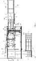
- FIG. 1 A top plan view of an example of the apparatus 10 is shown in Figure 1 .
- the unstacking station 12 is not included.
- the reference numeral 12 in Figure 1 merely designates the position where the unstacking station 12 is situated.
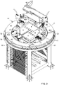
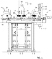
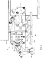
- An example of the unstacking station 12 is represented in Figures 2-4 .
- the apparatus includes a pallet buffer position 18 for storing empty pallets.
- the apparatus additionally includes a portal conveyor 24 with a gripper 28 for conveying an empty pallet P from the unstacking station 12 to the pallet buffer position 18.
- the pallet buffer position 18 and the portal conveyor 24 By virtue of the pallet buffer position 18 and the portal conveyor 24, intervention of an operator is not necessary either when the pallet P that is in the unstacking station 12 is empty.
- the apparatus establishes, for example with the aid of a sensor, that the pallet P is empty, the pallet P can be removed from the unstacking station and, via the portal conveyor 24, be brought into the pallet buffer position 18.
- the apparatus includes a cover buffer position 22 for storing covers C with which the at least two stacks of blanks on a pallet P are covered.
- the portal conveyor 24 with the gripper 28 is also for conveying a cover C from the unstacking station 12 to the cover buffer position 22.
- a cover C with which the stacks of blanks B that are on a pallet P are covered can be taken off the stacks and be carried off for temporary storage in the cover buffer position 22. What is thus accomplished is that this operation, too, is carried out in an automated manner without intervention of an operator.
- the apparatus additionally includes an intermediate sheet buffer position 26 for storing intermediate sheets I which extend at different height levels between the blanks B of the at least two stacks of blanks B.
- the portal conveyor 24 with the gripper 28 is also for conveying the intermediate sheets I from the unstacking station 12 to the intermediate sheet buffer position 26.
- the intermediate sheets I can be automatically taken off the stacks and stored in the intermediate sheet buffer position 26. Intervention of an operator is not necessary.
- a portal 24a is visible which is mobile over a rail or rails 24b.
- the gripper 28 is disposed so as to be displaceable in the length direction of the portal 24a and movable up and down.
- the gripper 28 is configured for picking up a pallet P, a cover C or an intermediate sheet I at the unstacking station 12, and for delivering a pallet P to the pallet buffer position 18, a cover C to the cover buffer position 22, and for delivering an intermediate sheet I to the intermediate sheet buffer position 26.
- a portal conveyor 24 extends above the unstacking station 12 and the various buffer positions 18, 22, 26, and with the aid of the gripper 28 both pallets P, covers C and intermediate sheets I can be picked up and conveyed from the unstacking station 12 to, respectively, the pallet buffer position 18, the cover buffer position 22 and the intermediate sheet buffer position 26.
- a portal solution takes up relatively little floor area which is advantageous from the viewpoint of factory space utilization.
- the gripper 28 may be provided with suction cups 30 for picking up intermediate sheets I.
- the gripper 28 may then be additionally provided with mechanical gripper arms 20 for picking up pallets P. From a safety point of view, such a gripper 28 is advantageous.
- the suction cups 30 were also used for picking up pallets P, and if the reduced pressure in the suction cups 30 should fall away, then a heavy pallet P would fall down directly, with risk of injury to the operator. Since the intermediate sheets I are made from cardboard and so are relatively vulnerable, engagement with mechanical gripper arms is less suitable. Hence, it is preferred to use mechanical gripper arms 20 for the pallets P and the suction cups 30 for the intermediate sheets I.
- suction cups 30 and/or the gripper arms 20 may be configured for picking up a cover C.
- a cover C in this context is formed by an upper half of a pallet and the cover C is therefore a stiff construction of wood.
- the gripper arms 20 will be used for picking up a cover.
- the suction cups 30 may be used for picking up a cover C.
- a discharge track 19 for empty pallets P and for covers C there is further shown a discharge track 19 for empty pallets P and for covers C.
- the discharge track 19 in the example shown is implemented as a chain path, but roller conveyors or conveyor belts may also be employed for this purpose.
- the feed track 14 in the example shown is implemented as a chain path 14a, 14c in which an aligning buffer 14b is included.
- the aligning buffer 14b comprises a number of rollers which are disposed so as to slope to one longitudinal edge, so that upon transport of a pallet P over this aligning buffer 14b, the pallet P is aligned against the relevant longitudinal edge of the aligning buffer 14b.
- the unstacking station 12 may include a lift 32 on which a pallet P with at least two stacks of blanks B is placeable.
- the apparatus 10 is provided with an electronic control for operating the lift 32, such that an upper side of the at least two stacks of blanks B is held at substantially the same level during unstacking.
- the mechanism with the aid of which the blanks are picked up from the stacks can be made of relatively simple design because it can pick up the blanks B each time at approximately the same position.
- the unstacking station 12 can comprise at least two robots 34.
- a robot 34 is associated with each stack of the at least two stacks.
- the robots 34 are then provided with a robot arm 36 having at the free end a pickup mechanism 38 for picking up a single blank B from the stack of blanks with which the respective robot 34 is associated.
- the unstacking station 12 includes at least one blank intermediate discharge track 40, 42, 44, 46.
- the at least two robots 34 are then each configured for delivering a blank B situated in the pickup mechanism 38 to a blank intermediate discharge track 40, 42, 44, 46.
- Singulation of the individual blanks B of the stacks takes place with the aid of robots 34, whereby each stack is unstacked by the robot 34 associated with that stack.
- This provides the advantage that the unstacking of the at least two stacks - the example involves four stacks - can take place simultaneously.
- a blank B can be taken off the stack.
- four robots 34 performing this activity simultaneously, at the exit of the unstacking station 12 every 3 ⁇ 4 s a blank can be delivered to the blank main discharge assembly 16.
- each robot 34 may be a SCARA robot.
- SCARA robots are standard commercially available robots and are particularly reliable in operation while their cost price is acceptable, partly because the control of a SCARA robot is relatively simple.
- SCARA is an abbreviation of Selective Compliance Articulated Robot Arm.
- each robot 34 may be associated with a respective corresponding blank intermediate discharge track 40, 42, 44, 46, such that the number of blank intermediate discharge tracks 40, 42, 44, 46 corresponds to the number of robots 34.
- Each blank intermediate discharge track 40, 42, 44, 46 may then traverse a spiral path over a segment of a circle.
- a starting point 40A, 42A, 44A, 46A of the spiral path of the blank intermediate discharge track 40, 42, 44, 46 belonging to a robot is in the proximity of the robot 34 associated with the respective blank intermediate discharge track 40, 42, 44, 46.
- Each blank intermediate discharge track 40, 42, 44, 46 has an end point 40B, 42B, 44B, 46B and the end points 40B, 42B, 44B, 46B of the at least two blank discharge tracks 40, 42, 44, 46 are located above each other. Furthermore, in this embodiment the spiral paths of the at least two blank intermediate discharge tracks 40, 42, 44, 46 are located above each other.
- An in-feed side 16A of the blank main discharge assembly 16 is near the end points 40B, 42B, 44B, 46B, such that blanks B that are on the end points 40B, 42B, 44B, 46B of the blank intermediate discharge tracks 40, 42, 44, 46 are transferrable onto or into the blank main discharge assembly 16.
- the blank intermediate discharge tracks 40-46 in this embodiment can be implemented relatively simply, for example as spiral plate parts which, for example, are connected on the radially inwardly facing longitudinal edge with an upstanding wall part 41 of small height.
- the blank discharge tracks 40-46 may not only be disposed in a manner inclined in tangential direction, so that they traverse a spiral path, but may also be disposed in a manner inclined in radial direction.
- the radially inner edge of the blank discharge track can be in a lower position than a radially outer edge of the blank discharge track. Due to this inclination in radial direction, the blanks B will tend, under the influence of gravity, to slide against the upstanding wall part 41, so that the position of the blanks on the blank intermediate discharge tracks 40-46 is well-defined and stable.
- the apparatus may include a cam intermediate conveyor.
- a cam intermediate conveyor comprises a cam chain or cam belt 50 which extends over a circular segmental path which is substantially concentric with the spiral paths of the at least two blank intermediate discharge tracks 40, 42, 44, 46.
- cams 52 which are configured for, upon transport of the cam chain or cam belt 50 and hence upon displacement of respective cams 52 along the spiral paths, pushing on blanks B that are on the blank intermediate discharge tracks 40, 42, 44, 46 over the respective blank intermediate discharge tracks 40, 42, 44, 46 to the endpoints 40B, 42B, 44B, 46B of those respective blank intermediate discharge tracks 40, 42, 44, 46.
- a blank B is represented which is on the blank intermediate discharge track 40 and is pushed on over this blank intermediate discharge track 40 by a cam 52. It is clear that, in use, by each cam a blank B is pushed on over one of the blank intermediate discharge tracks 40, 42, 44, 46. For the purpose of clarity, however, only one blank B is shown on the blank intermediate discharge tracks 40-46.
- Such a construction is relatively inexpensive in that a minimum number of moving parts are involved. Only the cam intermediate conveyor requires a motor for driving the cam chain or cam belt 50. As a result, this embodiment is particularly reliable in operation. Moreover, the blank intermediate discharge tracks 40, 42, 44, 46 provide a compact construction which takes up little floor area in that the blank intermediate discharge tracks 40, 42, 44, 46 extend above each other. The unstacking station 12 in this embodiment can therefore be of compact design.
- the cam chain or cam belt 50 may be moved on continuously or intermittently. The preference is an intermittent transport.
- the cam chain or cam belt 50 may be provided with cams which are at a mutual distance such that on the blank intermediate discharge tracks 40, 42, 44, 46 there can be blanks in each sector of 45°.
- the cam chain or cam belt 50 makes, a cam 52 as mentioned then moves through an angle of approximately 45° further along the spiral paths which the blank intermediate discharge tracks 40, 42, 44, 46 traverse.
- a cam 52 only one blank B is pushed on.
- each cam 52 four blanks B are propelled.
- the cam chain or cam belt 50 extends on the radially outer side of the blank intermediate discharge tracks 40-46.
- the cam chain or cam belt 50 extends on a radially inner side of the blank intermediate discharge tracks 40-46.
- the radial inclination of the blank intermediate discharge tracks 40-46 will then be precisely such that a radially inner side of a blank intermediate discharge track 40-46 lies higher than the radially outer side thereof.
- the blank intermediate discharge tracks 40-46 are each provided with a central recess which extends throughout the length of the path of the respective blank intermediate discharge tracks 40-46.
- the cam chain or cam belt 50 may then extend under the blank intermediate discharge tracks 40-46, and the cams 52 can extend through the central recess.
- both longitudinal edges of the blank intermediate discharge tracks are provided with an upstanding wall part of small height.
- the blanks B are then moved forward over the blank intermediate discharge tracks 40-46 between two upstanding wall parts, whereby the chance of the blanks B falling off the blank intermediate discharge tracks 40-46 has been wholly minimized.
- the blank main discharge assembly 16 can comprise a gripper chain which includes a conveyor chain with grippers 17 attached thereto. Each gripper is then configured for engaging a single blank B.
- gripper chains are known, for example for conveying printed newspapers in a machine room, so that a further explanation thereof is not necessary.
- An example of a supplier of such gripper chains is Ferag AG.
- the blank main discharge assembly 16 may also be implemented as a conveyor track or conveyor belt onto which the individual blanks collected at the end points 40B, 42B, 44B, 46B can be transferred, for example by a cam discharge conveyor, not shown, which is disposed at the end points 40B, 42B, 44B, 46B of the blank intermediate discharge tracks 40, 42, 44, 46.
- the cam discharge conveyor may be provided, in this embodiment, with a discharge chain or discharge belt and with a number of discharge cams which are connected with the discharge chain or discharge belt.
- the number of discharge cams corresponds to, or is a multiple of, the number of blank intermediate discharge tracks 40, 42, 44, 46.
- each blank intermediate discharge track 40, 42, 44, 46 at least one discharge cam is associated, whose length is such that it exclusively propels blanks B of the blank intermediate discharge track 40, 42, 44, 46 with which the respective discharge cam is associated.
- the discharge cams of different lengths are connected with the discharge chain or discharge belt, viewed along the length thereof, in spaced relation and in succession.
- blanks B which are in the end positions 40B, 42B, 44B, 46B of the blank intermediate discharge tracks 40, 42, 44, 46 are then, upon the discharge chain or discharge belt being driven, successively transferred from the blank intermediate discharge track end points 40B, 42B, 44B, 46B, located above each other, to the in-feed side of the blank main discharge assembly implemented as conveyor belt or conveyor track.
- the apparatus 10 may be provided, for the purpose of the transfer of the individual blanks from the end points 40B, 42B, 44B, 46B to the grippers 17, with a transfer assembly 56 (see Figure 3 ) which is disposed at the end points 40B, 42B, 44B, 46B of the blank intermediate discharge tracks 40, 42, 44, 46.
- the transfer assembly 56 may then be provided with a pusher cam 54 and the transfer assembly 56 is configured for positioning the pusher cam 54 on an upstream side of the blanks B which are at the end points 40B, 42B, 44B, 46B.
- the cam 54 When a set of four blanks B arrives at the end points 40B-46B, the cam 54 is in the upwardly moved position, so that the blanks B can pass the cam.
- the cam 54 of the transfer assembly 56 can move down, so that it is on the upstream side of the blanks B.
- the transfer assembly 56 is additionally configured to proceed to push the blanks B concerned simultaneously each in a direction of a gripper 17, such that each blank B is engageable by a corresponding gripper 17 for transport to a further processing device.
- the apparatus 10 can comprise a vision system 60 which is configured to record the position of an uppermost blank B which is on a stack. Also present then is a control 62 which is arranged for, depending on the recorded position of a respective blank B, controlling the robot 34 which is associated with the respective stack, such that the pickup mechanism 38 is positioned in a proper pickup position for picking up the respective blank B and that, after picking up of the blank B, the pickup mechanism 38 is positioned in the proper delivery position for correctly placing the respective blank B on the blank intermediate discharge track 40, 42, 44, 46 associated with that robot 34.
- each blank B within a stack do not lie entirely straight or, for example, are staggered.
- the orientation of each blank B on the stack can be determined and the robot 34 can be controlled such that both the pickup of the respective blank B and the placement thereof on a blank intermediate discharge track 40-46 proceed as desired, that is, each blank B is correctly positioned and oriented on the blank intermediate discharge track 40-46.
- the pickup mechanism 38 at the end of the robot arm 36 of each robot 34 can comprise a vacuum gripper which is provided with at least one suction cup 66 for engaging a blank B.
- the vacuum gripper is then preferably configured for lifting up a side of a blank B engaged.
- the pickup mechanism 38 may comprise a mechanical gripper 68 for engaging the side of the blank B lifted up by the vacuum gripper.
- each stack of blanks B on the pallet P may have two robots associated with it.
- a first of the two robots associated with a stack is then provided with a vacuum gripper provided with at least one suction cup for engaging a blank B.
- the vacuum gripper is configured for lifting up a side of a blank B engaged.
- a second of the two robots associated with a stack is then provided with the pickup mechanism 38 mentioned which is implemented as a mechanical gripper 68 for engaging the side of the blank B lifted up by the vacuum gripper.
- the first of the two robots may already, with the aid of the vacuum gripper, be lifting a side of the next blank B, so that this side is directly engageable upon return of the robot arm 36 which carries the mechanical gripper 68.
- the lifting up of a side of the blanks is hence carried out simultaneously with the transport of the blanks from the stack to the blank intermediate discharge tracks 40-46. With this, the processing capacity of the apparatus 10 is further enlarged.
- the number of stacks of blanks B on a pallet P may be four and the unstacking station 12 is provided with four robots 34 and four blank intermediate discharge tracks 40, 42, 44, 46. Pallets P having four stacks of blanks B arranged on them is a regularly occurring situation and an unstacking station 12 implemented with four robots 34 provides the possibility to process such pallets P with four stacks in an efficient and automated manner.
- the blank main discharge assembly 16 may link up with a box setup device for setting up the blank to form a box.
- box setup devices are known per se, so that these do not require any further explanation here.
Landscapes
- Engineering & Computer Science (AREA)
- Mechanical Engineering (AREA)
- Robotics (AREA)
- Sheets, Magazines, And Separation Thereof (AREA)
- Stackable Containers (AREA)
- Pallets (AREA)
- Specific Conveyance Elements (AREA)
Claims (14)
- Appareil de dépilage automatique d'une palette (P) sur laquelle sont disposées au moins deux piles de flans (B), l'appareil comprenant :- - un poste de dépilage (12) configuré pour :• recevoir une palette (P) sur laquelle sont disposées au moins deux piles de flans (B) à l'état aplati ; et pour• retirer un à un des flans individuels (B) des au moins deux piles de flans (B) qui se trouvent sur une palette (P) qui est reçue dans le poste de dépilage (12);- une voie d'alimentation (14) pour le convoyage des palettes (P), la voie d'alimentation (14) se raccordant par une extrémité de décharge au poste de dépilage (12) en vue d'alimenter une palette avec des piles de flans (B) à dépiler vers le poste de dépilage (12) ;- un ensemble principal de déchargement de flans (16) pour décharger des flans individuels (B) vers une autre station de traitement ;- une position tampon de palettes (18) pour stocker des palettes vides ;- un convoyeur portique (24) muni d'un dispositif de préhension (28) ; caractérisé en ce que l'appareil comprend en outre :- une position tampon de couvertures (22) pour stocker des couvertures (C) avec lesquelles les au moins deux piles de flans sur une palette (P) sont recouvertes ;- une position tampon de feuilles intermédiaires (26) pour stocker des feuilles intermédiaires (I) qui s'étendent à différents niveaux de hauteur entre les flans (B) des au moins deux piles de flans (B);dans lequel le dispositif de préhension (28) est configuré pour saisir une palette (P), une couverture (C) ou une feuille intermédiaire (I) au niveau du poste de dépilage (12) et pour délivrer une palette (P) à la position tampon de palettes (18), un couvercle (C) à la position de tampon de couverture (22) et pour délivrer une feuille intermédiaire (I) à la position de tampon de feuilles intermédiaires (26).
- Appareil selon la revendication 1, dans lequel le dispositif de préhension (28) est pourvu de ventouses (30) pour saisir les feuilles intermédiaires (I), dans lequel le dispositif de préhension (28) est en outre pourvu de bras de préhension mécaniques (20) pour prélever des palettes (P), dans lequel des ventouses (30) et/ou les bras de préhension (20) sont en outre configurés pour saisir une couverture (C).
- Appareil selon l'une quelconque des revendications précédentes, dans lequel le poste de dépilage (12) comprend un élévateur (32) sur lequel une palette (P) avec au moins deux piles de flans (B) peut être placée, dans lequel l'appareil (10) comprend une commande électronique pour actionner l'élévateur (32), de sorte qu'un côté supérieur des au moins deux piles de flans (B) est maintenu sensiblement au même niveau pendant le dépilage.
- Appareil selon l'une quelconque des revendications précédentes, dans lequel le poste de dépilage (12) comprend :- au moins deux robots (34), dans lequel à chaque pile desdites au moins deux piles de flans qui sont sur la palette (P) un robot (34) est associé, dans lequel les robots (34) sont chacun pourvus d'un bras de robot ( 36) ayant à l'extrémité libre un mécanisme de prélèvement (38) pour prélever un seul flan (B) de la pile de flans avec laquelle le robot respectif (34) est associé ;- au moins une voie intermédiaire de décharge des flans (40, 42, 44, 46),- dans lequel les au moins deux robots (34) sont configurés chacun pour délivrer un flan (B) présente dans le mécanisme de prélèvement (38) à une voie de décharge intermédiaire des flans (40, 42, 44, 46).
- Appareil selon la revendication 4, dans lequel chaque robot (34) est un robot SCARA
- Appareil selon la revendication 4 ou 5, dans lequel chaque robot (34) est associé à une voie intermédiaire de décharge des flans respective (40, 42, 44, 46), de sorte que le nombre de voies intermédiaires de décharge des flans (40, 42, 44, 46) correspond au nombre de robots (34), dans lequel chaque voie intermédiaire de décharge des flans (40, 42, 44, 46) parcourt un chemin en spirale sur un segment de cercle, dans lequel un point de départ (40A, 42A, 44A, 46A) du trajet en spirale de la voie intermédiaire de décharge des flans (40, 42, 44, 46) appartenant à un robot se trouve à proximité du robot (34) qui est associé à la voie intermédiaire de décharge des flans respective (40, 42, 44, 46), dans lequel chaque voie intermédiaire de décharge des flans (40, 42, 44, 46) présente un point d'extrémité (40B, 42B, 44B, 46B), dans lequel les points d'extrémité (40B, 42B, 44B, 46B) de l'au moins deux voies intermédiaires de décharge des flans (40, 42, 44, 46) sont situées l'une au-dessus de l'autre, et dans lequel les trajets en spirale des au moins deux voies de décharge des flans (40, 42, 44, 46) sont situés l'un au-dessus de l'autre, dans lequel un côté d'alimentation (16A) de l'ensemble principal de déchargement de flans (16) est proche desdits points d'extrémité (40B, 42B, 44B, 46B), de sorte que les flans (B) qui sont au niveau des points d'extrémité (40B, 42B, 44B, 46B) des voies intermédiaires de décharge des flans (40, 42, 44, 46) sont transférables sur ou dans l'ensemble principal de déchargement de flans (16).
- Appareil selon la revendication 6, comprenant :- un convoyeur intermédiaire à cames comprenant :• une chaîne à cames ou une courroie à cames (50) qui s'étend sur un trajet segmentaire circulaire qui est sensiblement concentrique avec les trajets en spirale des au moins deux voies intermédiaires de décharge des flans (40, 42, 44, 46), o• des cames (52) qui sont reliées à la chaîne à cames ou à la courroie à cames (50) et sont configurées pour, lors du transport de la chaîne à cames ou de la courroie à cames (50) et donc lors du déplacement des cames (52) le long des trajets en spirale, pousser sur les flans (B) présents sur les voies de décharge des flans (40, 42, 44, 46) au dessus des voies intermédiaires de décharge des flans (40, 42, 44, 46) jusqu'aux points d'extrémité (40B, 42B, 44B, 46B) des voies intermédiaires de décharge des flans (40, 42, 44, 46).
- Appareil selon la revendication 6 ou 7, dans lequel l'ensemble principal de déchargement de flans comprend une chaîne de dispositifs de préhension (16) qui comprend une chaîne de convoyeur avec des dispositif de préhensions (17) attachés à celle-ci, dans lequel chaque dispositif de préhension (17) est configuré pour engager un seul flan (B).
- Appareil selon la revendication 8, comprenant :- un ensemble de transfert (56) qui est disposé aux extrémités (40B, 42B, 44B, 46B) des voies de décharge des flans (40, 42, 44, 46) ; dans lequel l'ensemble de transfert (56) est pourvu d'une came de poussée (54) et est configuré pour positionner la came de poussée (54) sur un côté en amont des flans (B) qui sont aux points d'extrémité (40B, 42B, 44B, 46B), dans lequel l'ensemble de transfert (56) est en outre configuré pour procéder à la poussée des flans (B) concernés simultanément chacun dans une direction d'un dispositif de préhension (17), de sorte que chaque flan (B) puisse être engagé par un dispositif de préhension correspondant (17 ) pour le transport vers un dispositif de traitement ultérieur.
- Appareil selon l'une quelconque des revendications 4 à 9, comprenant :- un système de vision (60) qui est configuré pour enregistrer la position d'un flan supérieure (B) présent sur une pile ;- une commande (62) qui est configurée pour, en fonction de la position enregistrée d'un flan respectif (B), commander le robot (34) qui est associé à la pile respective, de sorte que le mécanisme de prélèvement (38) est positionné dans une position correcte de prélèvement pour saisir le flan respectif (B) et en ce que, après le prélèvement du flan (B), le mécanisme de prélèvement (38) est positionné dans la position de livraison appropriée pour placer correctement le flan respectif (B) sur la voie intermédiaire de décharge des flans (40, 42, 44, 46) associée à ce robot (34).
- Appareil selon l'une quelconque des revendications 4 à 10, dans lequel le mécanisme de prélèvement (38) à l'extrémité du bras de robot (36) de chaque robot (34) comprend :- un dispositif de préhension par aspiration pourvu d'au moins une ventouse (66) pour engager un flan (B), dans lequel le dispositif de préhension par aspiration est configurée pour soulever un côté d'un flan engagé (B) ;- un dispositif de préhension mécanique (68) pour engager le côté du flan (B) soulevé par le dispositif de préhension par aspiration.
- Appareil selon l'une quelconque des revendications 1 à 10, dans lequel à chaque pile de flans (B) sur la palette (P), deux robots sont associés,dans lequel un premier parmi les deux robots appartenant à une pile est pourvu d'un dispositif de préhension par aspiration pourvu d'au moins une ventouse (66) pour engager un flan (B), dans lequel le dispositif de préhension par aspiration est configuré pour soulever un côté d'un flan engagé (B) ;dans lequel un deuxième parmi les deux robots appartenant à une pile est pourvu dudit mécanisme de prélèvement (38) qui est mis en œuvre comme un dispositif de préhension mécanique (68) pour engager le côté du flan (B) soulevé par le dispositif de préhension par aspiration.
- Appareil selon l'une quelconque des revendications précédentes, dans lequel le nombre de piles de flans (B) sur une palette (P) est de quatre et dans lequel le poste de dépilage (12) est pourvu de quatre robots (34) et de quatre voies intermédiaires de décharge des flans (40, 42, 44, 46).
- Appareil selon l'une quelconque des revendications précédentes, dans lequel l'ensemble principal de déchargement de flans (16) est relié à un dispositif d'assemblage de carton pour d'assemblage du flan pour former un carton.
Priority Applications (1)
| Application Number | Priority Date | Filing Date | Title |
|---|---|---|---|
| EP22189071.8A EP4105153B1 (fr) | 2017-05-12 | 2018-05-11 | Appareil pour désempiler automatiquement une palette sur lequel au moins deux piles de découpes sont disposées |
Applications Claiming Priority (1)
| Application Number | Priority Date | Filing Date | Title |
|---|---|---|---|
| NL2018907A NL2018907B1 (nl) | 2017-05-12 | 2017-05-12 | Inrichting voor het automatisch ontstapelen van een pallet waarop zich ten minste twee stapels plano’s zijn opgesteld |
Related Child Applications (2)
| Application Number | Title | Priority Date | Filing Date |
|---|---|---|---|
| EP22189071.8A Division EP4105153B1 (fr) | 2017-05-12 | 2018-05-11 | Appareil pour désempiler automatiquement une palette sur lequel au moins deux piles de découpes sont disposées |
| EP22189071.8A Division-Into EP4105153B1 (fr) | 2017-05-12 | 2018-05-11 | Appareil pour désempiler automatiquement une palette sur lequel au moins deux piles de découpes sont disposées |
Publications (2)
| Publication Number | Publication Date |
|---|---|
| EP3401253A1 EP3401253A1 (fr) | 2018-11-14 |
| EP3401253B1 true EP3401253B1 (fr) | 2022-10-26 |
Family
ID=59067852
Family Applications (2)
| Application Number | Title | Priority Date | Filing Date |
|---|---|---|---|
| EP18171794.3A Active EP3401253B1 (fr) | 2017-05-12 | 2018-05-11 | Appareil pour désempiler automatiquement une palette sur lequel au moins deux piles de découpes sont disposées |
| EP22189071.8A Active EP4105153B1 (fr) | 2017-05-12 | 2018-05-11 | Appareil pour désempiler automatiquement une palette sur lequel au moins deux piles de découpes sont disposées |
Family Applications After (1)
| Application Number | Title | Priority Date | Filing Date |
|---|---|---|---|
| EP22189071.8A Active EP4105153B1 (fr) | 2017-05-12 | 2018-05-11 | Appareil pour désempiler automatiquement une palette sur lequel au moins deux piles de découpes sont disposées |
Country Status (5)
| Country | Link |
|---|---|
| US (1) | US10633204B2 (fr) |
| EP (2) | EP3401253B1 (fr) |
| ES (1) | ES2933804T3 (fr) |
| FI (1) | FI3401253T3 (fr) |
| NL (1) | NL2018907B1 (fr) |
Families Citing this family (7)
| Publication number | Priority date | Publication date | Assignee | Title |
|---|---|---|---|---|
| CN112478718B (zh) * | 2020-12-10 | 2024-07-02 | 无锡先导智能装备股份有限公司 | 一种转运装置 |
| US11738956B2 (en) * | 2021-01-26 | 2023-08-29 | Target Brands, Inc. | Door and light curtain control system for depalletization systems and methods |
| CN114261750B (zh) * | 2021-12-28 | 2023-08-01 | 上海世禹精密设备股份有限公司 | 一种上料取片设备 |
| CN117302965B (zh) * | 2023-09-18 | 2025-11-14 | 锦耀智能精密制造(深圳)有限公司 | 一种物料摆盘机 |
| CN118323879B (zh) * | 2024-06-13 | 2024-08-13 | 山东金石机器人智能科技有限公司 | 一种窑炉自动装卸料生产线 |
| USD1110352S1 (en) | 2024-11-08 | 2026-01-27 | Avery Dennison Retail Information Services Llc | Display screen or portion thereof with graphical user interface |
| CN119218734A (zh) * | 2024-12-04 | 2024-12-31 | 江苏金三力机械制造有限公司 | 一种隧道钢拱架生产用的给料装置及工艺 |
Family Cites Families (10)
| Publication number | Priority date | Publication date | Assignee | Title |
|---|---|---|---|---|
| JPS533542B2 (fr) * | 1972-07-19 | 1978-02-07 | ||
| JPS62185646A (ja) * | 1986-02-10 | 1987-08-14 | Komatsu Ltd | デイスタツカ |
| US5336042A (en) * | 1992-03-05 | 1994-08-09 | Kinetic Robotics Inc. | Palletizer with cap forming |
| JPH07101550A (ja) * | 1993-10-06 | 1995-04-18 | Shibuya Kogyo Co Ltd | 物品処理装置 |
| ATE496711T1 (de) * | 2008-03-12 | 2011-02-15 | Schuler Automation Gmbh & Co | Vorrichtung und verfahren zur lageausrichtung von plattenförmigen teilen |
| US7993095B2 (en) * | 2008-10-30 | 2011-08-09 | Graham Packaging Company, L.P. | Mobile split palletizer |
| FR2957905B1 (fr) * | 2010-03-29 | 2012-04-06 | Otor Sa | Procede et dispositif de transfert de decoupes pour boites d'emballage |
| JP5633500B2 (ja) * | 2011-11-04 | 2014-12-03 | 株式会社安川電機 | 荷役装置及び荷役方法 |
| HRP20160763T1 (hr) * | 2011-12-20 | 2016-08-12 | Ludwig BRANDMÜLLER | Sustav za depaletiziranje i jedinica za uklanjanje |
| EP3247660B1 (fr) * | 2015-01-19 | 2021-02-24 | Krones Aktiengesellschaft | Procédé et dispositif de manipulation des couches intermédiaires individuelles |
-
2017
- 2017-05-12 NL NL2018907A patent/NL2018907B1/nl not_active IP Right Cessation
-
2018
- 2018-05-11 EP EP18171794.3A patent/EP3401253B1/fr active Active
- 2018-05-11 US US15/977,527 patent/US10633204B2/en active Active
- 2018-05-11 ES ES18171794T patent/ES2933804T3/es active Active
- 2018-05-11 EP EP22189071.8A patent/EP4105153B1/fr active Active
- 2018-05-11 FI FIEP18171794.3T patent/FI3401253T3/fi active
Also Published As
| Publication number | Publication date |
|---|---|
| EP4105153B1 (fr) | 2023-09-20 |
| US10633204B2 (en) | 2020-04-28 |
| EP3401253A1 (fr) | 2018-11-14 |
| EP4105153A1 (fr) | 2022-12-21 |
| FI3401253T3 (fi) | 2023-01-13 |
| US20180327201A1 (en) | 2018-11-15 |
| EP4105153C0 (fr) | 2023-09-20 |
| ES2933804T3 (es) | 2023-02-14 |
| NL2018907B1 (nl) | 2018-11-15 |
Similar Documents
| Publication | Publication Date | Title |
|---|---|---|
| EP3401253B1 (fr) | Appareil pour désempiler automatiquement une palette sur lequel au moins deux piles de découpes sont disposées | |
| US4541762A (en) | Apparatus for loading and/or unloading machine tools or the like | |
| AU2012257735B2 (en) | Method for storing and/or order-picking product units | |
| US10604361B2 (en) | Case manipulator for a palletizer system | |
| US4720228A (en) | Automatic parts handling apparatus | |
| EP2208695A1 (fr) | Machine et procédé de palettisation | |
| GB2189209A (en) | Loading cartons on to pallets | |
| US20060245858A1 (en) | Apparatus for forming a sequence of load carriers by means of a temporary store, and method for temporary storage | |
| EP1231170A1 (fr) | Machine d'alimentation des bôites en carton vides | |
| CN212863004U (zh) | 用于处理以至少一排相继运动的成件货物的设备 | |
| US7690884B2 (en) | Finger and disk for separating plate-shaped objects, particularly battery plates | |
| CN218200283U (zh) | 烟箱拆码垛贴标系统 | |
| US20100017014A1 (en) | Apparatus for separating plate-shaped objects | |
| US5807065A (en) | Apparatus for automatically unstacking horizontal lid members from a vertically extending stack thereof | |
| JPH04226221A (ja) | 物品の積上げ装置 | |
| US12428181B2 (en) | System and method for handling packaging units, and manipulator unit | |
| US11427361B2 (en) | Device and method for filling containers with value documents, in particular banknotes, and system for processing value documents | |
| EP3450362B1 (fr) | Dispositif pour charger un groupe de produits sur une palette | |
| JP7161256B1 (ja) | トラックへの積載方法及びその積載装置 | |
| CN115489920B (zh) | 烟箱拆码垛贴标系统与方法 | |
| JPH0822698B2 (ja) | びん用積降し装置 | |
| JPH07300229A (ja) | 移載搬送装置 | |
| JPH0977267A (ja) | 荷降し・荷積み装置 | |
| CN113135033A (zh) | 用于对印刷版进行分单的设备 | |
| US3502231A (en) | Material handling system |
Legal Events
| Date | Code | Title | Description |
|---|---|---|---|
| PUAI | Public reference made under article 153(3) epc to a published international application that has entered the european phase |
Free format text: ORIGINAL CODE: 0009012 |
|
| STAA | Information on the status of an ep patent application or granted ep patent |
Free format text: STATUS: THE APPLICATION HAS BEEN PUBLISHED |
|
| AK | Designated contracting states |
Kind code of ref document: A1 Designated state(s): AL AT BE BG CH CY CZ DE DK EE ES FI FR GB GR HR HU IE IS IT LI LT LU LV MC MK MT NL NO PL PT RO RS SE SI SK SM TR |
|
| AX | Request for extension of the european patent |
Extension state: BA ME |
|
| STAA | Information on the status of an ep patent application or granted ep patent |
Free format text: STATUS: REQUEST FOR EXAMINATION WAS MADE |
|
| 17P | Request for examination filed |
Effective date: 20190513 |
|
| RBV | Designated contracting states (corrected) |
Designated state(s): AL AT BE BG CH CY CZ DE DK EE ES FI FR GB GR HR HU IE IS IT LI LT LU LV MC MK MT NL NO PL PT RO RS SE SI SK SM TR |
|
| GRAP | Despatch of communication of intention to grant a patent |
Free format text: ORIGINAL CODE: EPIDOSNIGR1 |
|
| STAA | Information on the status of an ep patent application or granted ep patent |
Free format text: STATUS: GRANT OF PATENT IS INTENDED |
|
| INTG | Intention to grant announced |
Effective date: 20220609 |
|
| GRAS | Grant fee paid |
Free format text: ORIGINAL CODE: EPIDOSNIGR3 |
|
| GRAA | (expected) grant |
Free format text: ORIGINAL CODE: 0009210 |
|
| STAA | Information on the status of an ep patent application or granted ep patent |
Free format text: STATUS: THE PATENT HAS BEEN GRANTED |
|
| AK | Designated contracting states |
Kind code of ref document: B1 Designated state(s): AL AT BE BG CH CY CZ DE DK EE ES FI FR GB GR HR HU IE IS IT LI LT LU LV MC MK MT NL NO PL PT RO RS SE SI SK SM TR |
|
| REG | Reference to a national code |
Ref country code: GB Ref legal event code: FG4D |
|
| REG | Reference to a national code |
Ref country code: CH Ref legal event code: EP |
|
| REG | Reference to a national code |
Ref country code: DE Ref legal event code: R096 Ref document number: 602018042155 Country of ref document: DE |
|
| REG | Reference to a national code |
Ref country code: AT Ref legal event code: REF Ref document number: 1526918 Country of ref document: AT Kind code of ref document: T Effective date: 20221115 |
|
| REG | Reference to a national code |
Ref country code: IE Ref legal event code: FG4D |
|
| REG | Reference to a national code |
Ref country code: DK Ref legal event code: T3 Effective date: 20221220 |
|
| REG | Reference to a national code |
Ref country code: SE Ref legal event code: TRGR |
|
| REG | Reference to a national code |
Ref country code: NL Ref legal event code: FP |
|
| REG | Reference to a national code |
Ref country code: LT Ref legal event code: MG9D |
|
| REG | Reference to a national code |
Ref country code: ES Ref legal event code: FG2A Ref document number: 2933804 Country of ref document: ES Kind code of ref document: T3 Effective date: 20230214 |
|
| REG | Reference to a national code |
Ref country code: AT Ref legal event code: MK05 Ref document number: 1526918 Country of ref document: AT Kind code of ref document: T Effective date: 20221026 |
|
| PG25 | Lapsed in a contracting state [announced via postgrant information from national office to epo] |
Ref country code: PT Free format text: LAPSE BECAUSE OF FAILURE TO SUBMIT A TRANSLATION OF THE DESCRIPTION OR TO PAY THE FEE WITHIN THE PRESCRIBED TIME-LIMIT Effective date: 20230227 Ref country code: NO Free format text: LAPSE BECAUSE OF FAILURE TO SUBMIT A TRANSLATION OF THE DESCRIPTION OR TO PAY THE FEE WITHIN THE PRESCRIBED TIME-LIMIT Effective date: 20230126 Ref country code: LT Free format text: LAPSE BECAUSE OF FAILURE TO SUBMIT A TRANSLATION OF THE DESCRIPTION OR TO PAY THE FEE WITHIN THE PRESCRIBED TIME-LIMIT Effective date: 20221026 Ref country code: AT Free format text: LAPSE BECAUSE OF FAILURE TO SUBMIT A TRANSLATION OF THE DESCRIPTION OR TO PAY THE FEE WITHIN THE PRESCRIBED TIME-LIMIT Effective date: 20221026 |
|
| PG25 | Lapsed in a contracting state [announced via postgrant information from national office to epo] |
Ref country code: RS Free format text: LAPSE BECAUSE OF FAILURE TO SUBMIT A TRANSLATION OF THE DESCRIPTION OR TO PAY THE FEE WITHIN THE PRESCRIBED TIME-LIMIT Effective date: 20221026 Ref country code: PL Free format text: LAPSE BECAUSE OF FAILURE TO SUBMIT A TRANSLATION OF THE DESCRIPTION OR TO PAY THE FEE WITHIN THE PRESCRIBED TIME-LIMIT Effective date: 20221026 Ref country code: LV Free format text: LAPSE BECAUSE OF FAILURE TO SUBMIT A TRANSLATION OF THE DESCRIPTION OR TO PAY THE FEE WITHIN THE PRESCRIBED TIME-LIMIT Effective date: 20221026 Ref country code: IS Free format text: LAPSE BECAUSE OF FAILURE TO SUBMIT A TRANSLATION OF THE DESCRIPTION OR TO PAY THE FEE WITHIN THE PRESCRIBED TIME-LIMIT Effective date: 20230226 Ref country code: HR Free format text: LAPSE BECAUSE OF FAILURE TO SUBMIT A TRANSLATION OF THE DESCRIPTION OR TO PAY THE FEE WITHIN THE PRESCRIBED TIME-LIMIT Effective date: 20221026 Ref country code: GR Free format text: LAPSE BECAUSE OF FAILURE TO SUBMIT A TRANSLATION OF THE DESCRIPTION OR TO PAY THE FEE WITHIN THE PRESCRIBED TIME-LIMIT Effective date: 20230127 |
|
| PGFP | Annual fee paid to national office [announced via postgrant information from national office to epo] |
Ref country code: NL Payment date: 20230425 Year of fee payment: 6 |
|
| REG | Reference to a national code |
Ref country code: DE Ref legal event code: R097 Ref document number: 602018042155 Country of ref document: DE |
|
| PG25 | Lapsed in a contracting state [announced via postgrant information from national office to epo] |
Ref country code: SM Free format text: LAPSE BECAUSE OF FAILURE TO SUBMIT A TRANSLATION OF THE DESCRIPTION OR TO PAY THE FEE WITHIN THE PRESCRIBED TIME-LIMIT Effective date: 20221026 Ref country code: RO Free format text: LAPSE BECAUSE OF FAILURE TO SUBMIT A TRANSLATION OF THE DESCRIPTION OR TO PAY THE FEE WITHIN THE PRESCRIBED TIME-LIMIT Effective date: 20221026 Ref country code: EE Free format text: LAPSE BECAUSE OF FAILURE TO SUBMIT A TRANSLATION OF THE DESCRIPTION OR TO PAY THE FEE WITHIN THE PRESCRIBED TIME-LIMIT Effective date: 20221026 Ref country code: CZ Free format text: LAPSE BECAUSE OF FAILURE TO SUBMIT A TRANSLATION OF THE DESCRIPTION OR TO PAY THE FEE WITHIN THE PRESCRIBED TIME-LIMIT Effective date: 20221026 |
|
| PGFP | Annual fee paid to national office [announced via postgrant information from national office to epo] |
Ref country code: DK Payment date: 20230524 Year of fee payment: 6 Ref country code: DE Payment date: 20230519 Year of fee payment: 6 |
|
| PG25 | Lapsed in a contracting state [announced via postgrant information from national office to epo] |
Ref country code: SK Free format text: LAPSE BECAUSE OF FAILURE TO SUBMIT A TRANSLATION OF THE DESCRIPTION OR TO PAY THE FEE WITHIN THE PRESCRIBED TIME-LIMIT Effective date: 20221026 Ref country code: AL Free format text: LAPSE BECAUSE OF FAILURE TO SUBMIT A TRANSLATION OF THE DESCRIPTION OR TO PAY THE FEE WITHIN THE PRESCRIBED TIME-LIMIT Effective date: 20221026 |
|
| PLBE | No opposition filed within time limit |
Free format text: ORIGINAL CODE: 0009261 |
|
| STAA | Information on the status of an ep patent application or granted ep patent |
Free format text: STATUS: NO OPPOSITION FILED WITHIN TIME LIMIT |
|
| PGFP | Annual fee paid to national office [announced via postgrant information from national office to epo] |
Ref country code: BE Payment date: 20230519 Year of fee payment: 6 |
|
| 26N | No opposition filed |
Effective date: 20230727 |
|
| PG25 | Lapsed in a contracting state [announced via postgrant information from national office to epo] |
Ref country code: SI Free format text: LAPSE BECAUSE OF FAILURE TO SUBMIT A TRANSLATION OF THE DESCRIPTION OR TO PAY THE FEE WITHIN THE PRESCRIBED TIME-LIMIT Effective date: 20221026 |
|
| REG | Reference to a national code |
Ref country code: CH Ref legal event code: PL |
|
| REG | Reference to a national code |
Ref country code: SE Ref legal event code: EUG |
|
| PG25 | Lapsed in a contracting state [announced via postgrant information from national office to epo] |
Ref country code: MC Free format text: LAPSE BECAUSE OF FAILURE TO SUBMIT A TRANSLATION OF THE DESCRIPTION OR TO PAY THE FEE WITHIN THE PRESCRIBED TIME-LIMIT Effective date: 20221026 |
|
| GBPC | Gb: european patent ceased through non-payment of renewal fee |
Effective date: 20230511 |
|
| PG25 | Lapsed in a contracting state [announced via postgrant information from national office to epo] |
Ref country code: SE Free format text: LAPSE BECAUSE OF NON-PAYMENT OF DUE FEES Effective date: 20230512 Ref country code: MC Free format text: LAPSE BECAUSE OF FAILURE TO SUBMIT A TRANSLATION OF THE DESCRIPTION OR TO PAY THE FEE WITHIN THE PRESCRIBED TIME-LIMIT Effective date: 20221026 Ref country code: LU Free format text: LAPSE BECAUSE OF NON-PAYMENT OF DUE FEES Effective date: 20230511 Ref country code: LI Free format text: LAPSE BECAUSE OF NON-PAYMENT OF DUE FEES Effective date: 20230531 Ref country code: FI Free format text: LAPSE BECAUSE OF NON-PAYMENT OF DUE FEES Effective date: 20230511 Ref country code: CH Free format text: LAPSE BECAUSE OF NON-PAYMENT OF DUE FEES Effective date: 20230531 |
|
| REG | Reference to a national code |
Ref country code: IE Ref legal event code: MM4A |
|
| PG25 | Lapsed in a contracting state [announced via postgrant information from national office to epo] |
Ref country code: IE Free format text: LAPSE BECAUSE OF NON-PAYMENT OF DUE FEES Effective date: 20230511 |
|
| PG25 | Lapsed in a contracting state [announced via postgrant information from national office to epo] |
Ref country code: IT Free format text: LAPSE BECAUSE OF NON-PAYMENT OF DUE FEES Effective date: 20230511 Ref country code: IE Free format text: LAPSE BECAUSE OF NON-PAYMENT OF DUE FEES Effective date: 20230511 Ref country code: GB Free format text: LAPSE BECAUSE OF NON-PAYMENT OF DUE FEES Effective date: 20230511 |
|
| PG25 | Lapsed in a contracting state [announced via postgrant information from national office to epo] |
Ref country code: FR Free format text: LAPSE BECAUSE OF NON-PAYMENT OF DUE FEES Effective date: 20230531 |
|
| REG | Reference to a national code |
Ref country code: ES Ref legal event code: FD2A Effective date: 20240627 |
|
| PG25 | Lapsed in a contracting state [announced via postgrant information from national office to epo] |
Ref country code: ES Free format text: LAPSE BECAUSE OF NON-PAYMENT OF DUE FEES Effective date: 20230512 |
|
| PG25 | Lapsed in a contracting state [announced via postgrant information from national office to epo] |
Ref country code: ES Free format text: LAPSE BECAUSE OF NON-PAYMENT OF DUE FEES Effective date: 20230512 |
|
| PG25 | Lapsed in a contracting state [announced via postgrant information from national office to epo] |
Ref country code: BG Free format text: LAPSE BECAUSE OF FAILURE TO SUBMIT A TRANSLATION OF THE DESCRIPTION OR TO PAY THE FEE WITHIN THE PRESCRIBED TIME-LIMIT Effective date: 20221026 |
|
| PG25 | Lapsed in a contracting state [announced via postgrant information from national office to epo] |
Ref country code: BG Free format text: LAPSE BECAUSE OF FAILURE TO SUBMIT A TRANSLATION OF THE DESCRIPTION OR TO PAY THE FEE WITHIN THE PRESCRIBED TIME-LIMIT Effective date: 20221026 |
|
| REG | Reference to a national code |
Ref country code: DE Ref legal event code: R119 Ref document number: 602018042155 Country of ref document: DE |
|
| REG | Reference to a national code |
Ref country code: DK Ref legal event code: EBP Effective date: 20240531 |
|
| REG | Reference to a national code |
Ref country code: NL Ref legal event code: MM Effective date: 20240601 |
|
| PG25 | Lapsed in a contracting state [announced via postgrant information from national office to epo] |
Ref country code: NL Free format text: LAPSE BECAUSE OF NON-PAYMENT OF DUE FEES Effective date: 20240601 |
|
| REG | Reference to a national code |
Ref country code: BE Ref legal event code: MM Effective date: 20240531 |
|
| PG25 | Lapsed in a contracting state [announced via postgrant information from national office to epo] |
Ref country code: DE Free format text: LAPSE BECAUSE OF NON-PAYMENT OF DUE FEES Effective date: 20241203 |
|
| PG25 | Lapsed in a contracting state [announced via postgrant information from national office to epo] |
Ref country code: DK Free format text: LAPSE BECAUSE OF NON-PAYMENT OF DUE FEES Effective date: 20240531 |
|
| PG25 | Lapsed in a contracting state [announced via postgrant information from national office to epo] |
Ref country code: BE Free format text: LAPSE BECAUSE OF NON-PAYMENT OF DUE FEES Effective date: 20240531 |
|
| PG25 | Lapsed in a contracting state [announced via postgrant information from national office to epo] |
Ref country code: CY Free format text: LAPSE BECAUSE OF FAILURE TO SUBMIT A TRANSLATION OF THE DESCRIPTION OR TO PAY THE FEE WITHIN THE PRESCRIBED TIME-LIMIT; INVALID AB INITIO Effective date: 20180511 |
|
| PG25 | Lapsed in a contracting state [announced via postgrant information from national office to epo] |
Ref country code: HU Free format text: LAPSE BECAUSE OF FAILURE TO SUBMIT A TRANSLATION OF THE DESCRIPTION OR TO PAY THE FEE WITHIN THE PRESCRIBED TIME-LIMIT; INVALID AB INITIO Effective date: 20180511 |
|
| PG25 | Lapsed in a contracting state [announced via postgrant information from national office to epo] |
Ref country code: TR Free format text: LAPSE BECAUSE OF FAILURE TO SUBMIT A TRANSLATION OF THE DESCRIPTION OR TO PAY THE FEE WITHIN THE PRESCRIBED TIME-LIMIT Effective date: 20221026 |