EP3401280A1 - Verfahren zur herstellung von ammoniak - Google Patents
Verfahren zur herstellung von ammoniak Download PDFInfo
- Publication number
- EP3401280A1 EP3401280A1 EP17170711.0A EP17170711A EP3401280A1 EP 3401280 A1 EP3401280 A1 EP 3401280A1 EP 17170711 A EP17170711 A EP 17170711A EP 3401280 A1 EP3401280 A1 EP 3401280A1
- Authority
- EP
- European Patent Office
- Prior art keywords
- stream
- hydrogen
- synthesis gas
- purge
- recovery
- Prior art date
- Legal status (The legal status is an assumption and is not a legal conclusion. Google has not performed a legal analysis and makes no representation as to the accuracy of the status listed.)
- Granted
Links
Images
Classifications
-
- C—CHEMISTRY; METALLURGY
- C01—INORGANIC CHEMISTRY
- C01C—AMMONIA; CYANOGEN; COMPOUNDS THEREOF
- C01C1/00—Ammonia; Compounds thereof
- C01C1/02—Preparation, purification or separation of ammonia
- C01C1/04—Preparation of ammonia by synthesis
- C01C1/0405—Preparation of ammonia by synthesis from N2 and H2 in presence of a catalyst
-
- C—CHEMISTRY; METALLURGY
- C01—INORGANIC CHEMISTRY
- C01B—NON-METALLIC ELEMENTS; COMPOUNDS THEREOF; METALLOIDS OR COMPOUNDS THEREOF NOT COVERED BY SUBCLASS C01C
- C01B3/00—Hydrogen; Gaseous mixtures containing hydrogen; Separation of hydrogen from mixtures containing it; Purification of hydrogen; Reversible storage of hydrogen
- C01B3/02—Production of hydrogen; Production of gaseous mixtures containing hydrogen
- C01B3/025—Preparation or purification of gas mixtures for ammonia synthesis
-
- C—CHEMISTRY; METALLURGY
- C01—INORGANIC CHEMISTRY
- C01B—NON-METALLIC ELEMENTS; COMPOUNDS THEREOF; METALLOIDS OR COMPOUNDS THEREOF NOT COVERED BY SUBCLASS C01C
- C01B3/00—Hydrogen; Gaseous mixtures containing hydrogen; Separation of hydrogen from mixtures containing it; Purification of hydrogen; Reversible storage of hydrogen
- C01B3/02—Production of hydrogen; Production of gaseous mixtures containing hydrogen
- C01B3/32—Production of hydrogen; Production of gaseous mixtures containing hydrogen by reaction of gaseous or liquid organic compounds with gasifying agents, e.g. water, carbon dioxide or air
- C01B3/34—Production of hydrogen; Production of gaseous mixtures containing hydrogen by reaction of gaseous or liquid organic compounds with gasifying agents, e.g. water, carbon dioxide or air by reaction of hydrocarbons with gasifying agents
- C01B3/38—Production of hydrogen; Production of gaseous mixtures containing hydrogen by reaction of gaseous or liquid organic compounds with gasifying agents, e.g. water, carbon dioxide or air by reaction of hydrocarbons with gasifying agents using catalysts
- C01B3/382—Processes with two or more reaction steps, of which at least one is catalytic, e.g. steam reforming and partial oxidation
-
- C—CHEMISTRY; METALLURGY
- C01—INORGANIC CHEMISTRY
- C01C—AMMONIA; CYANOGEN; COMPOUNDS THEREOF
- C01C1/00—Ammonia; Compounds thereof
- C01C1/02—Preparation, purification or separation of ammonia
- C01C1/04—Preparation of ammonia by synthesis
- C01C1/0405—Preparation of ammonia by synthesis from N2 and H2 in presence of a catalyst
- C01C1/0476—Purge gas treatment, e.g. for removal of inert gases or recovery of H2
-
- C—CHEMISTRY; METALLURGY
- C01—INORGANIC CHEMISTRY
- C01B—NON-METALLIC ELEMENTS; COMPOUNDS THEREOF; METALLOIDS OR COMPOUNDS THEREOF NOT COVERED BY SUBCLASS C01C
- C01B2203/00—Integrated processes for the production of hydrogen or synthesis gas
- C01B2203/02—Processes for making hydrogen or synthesis gas
- C01B2203/0205—Processes for making hydrogen or synthesis gas containing a reforming step
- C01B2203/0227—Processes for making hydrogen or synthesis gas containing a reforming step containing a catalytic reforming step
- C01B2203/0244—Processes for making hydrogen or synthesis gas containing a reforming step containing a catalytic reforming step the reforming step being an autothermal reforming step, e.g. secondary reforming processes
-
- C—CHEMISTRY; METALLURGY
- C01—INORGANIC CHEMISTRY
- C01B—NON-METALLIC ELEMENTS; COMPOUNDS THEREOF; METALLOIDS OR COMPOUNDS THEREOF NOT COVERED BY SUBCLASS C01C
- C01B2203/00—Integrated processes for the production of hydrogen or synthesis gas
- C01B2203/04—Integrated processes for the production of hydrogen or synthesis gas containing a purification step for the hydrogen or the synthesis gas
- C01B2203/0415—Purification by absorption in liquids
-
- C—CHEMISTRY; METALLURGY
- C01—INORGANIC CHEMISTRY
- C01B—NON-METALLIC ELEMENTS; COMPOUNDS THEREOF; METALLOIDS OR COMPOUNDS THEREOF NOT COVERED BY SUBCLASS C01C
- C01B2203/00—Integrated processes for the production of hydrogen or synthesis gas
- C01B2203/04—Integrated processes for the production of hydrogen or synthesis gas containing a purification step for the hydrogen or the synthesis gas
- C01B2203/042—Purification by adsorption on solids
- C01B2203/0425—In-situ adsorption process during hydrogen production
-
- C—CHEMISTRY; METALLURGY
- C01—INORGANIC CHEMISTRY
- C01B—NON-METALLIC ELEMENTS; COMPOUNDS THEREOF; METALLOIDS OR COMPOUNDS THEREOF NOT COVERED BY SUBCLASS C01C
- C01B2203/00—Integrated processes for the production of hydrogen or synthesis gas
- C01B2203/04—Integrated processes for the production of hydrogen or synthesis gas containing a purification step for the hydrogen or the synthesis gas
- C01B2203/042—Purification by adsorption on solids
- C01B2203/043—Regenerative adsorption process in two or more beds, one for adsorption, the other for regeneration
-
- C—CHEMISTRY; METALLURGY
- C01—INORGANIC CHEMISTRY
- C01B—NON-METALLIC ELEMENTS; COMPOUNDS THEREOF; METALLOIDS OR COMPOUNDS THEREOF NOT COVERED BY SUBCLASS C01C
- C01B2203/00—Integrated processes for the production of hydrogen or synthesis gas
- C01B2203/04—Integrated processes for the production of hydrogen or synthesis gas containing a purification step for the hydrogen or the synthesis gas
- C01B2203/0465—Composition of the impurity
- C01B2203/0475—Composition of the impurity the impurity being carbon dioxide
-
- C—CHEMISTRY; METALLURGY
- C01—INORGANIC CHEMISTRY
- C01B—NON-METALLIC ELEMENTS; COMPOUNDS THEREOF; METALLOIDS OR COMPOUNDS THEREOF NOT COVERED BY SUBCLASS C01C
- C01B2203/00—Integrated processes for the production of hydrogen or synthesis gas
- C01B2203/14—Details of the flowsheet
- C01B2203/146—At least two purification steps in series
-
- C—CHEMISTRY; METALLURGY
- C01—INORGANIC CHEMISTRY
- C01B—NON-METALLIC ELEMENTS; COMPOUNDS THEREOF; METALLOIDS OR COMPOUNDS THEREOF NOT COVERED BY SUBCLASS C01C
- C01B3/00—Hydrogen; Gaseous mixtures containing hydrogen; Separation of hydrogen from mixtures containing it; Purification of hydrogen; Reversible storage of hydrogen
- C01B3/02—Production of hydrogen; Production of gaseous mixtures containing hydrogen
- C01B3/32—Production of hydrogen; Production of gaseous mixtures containing hydrogen by reaction of gaseous or liquid organic compounds with gasifying agents, e.g. water, carbon dioxide or air
- C01B3/34—Production of hydrogen; Production of gaseous mixtures containing hydrogen by reaction of gaseous or liquid organic compounds with gasifying agents, e.g. water, carbon dioxide or air by reaction of hydrocarbons with gasifying agents
- C01B3/48—Production of hydrogen; Production of gaseous mixtures containing hydrogen by reaction of gaseous or liquid organic compounds with gasifying agents, e.g. water, carbon dioxide or air by reaction of hydrocarbons with gasifying agents followed by reaction of water vapour with carbon monoxide
-
- Y—GENERAL TAGGING OF NEW TECHNOLOGICAL DEVELOPMENTS; GENERAL TAGGING OF CROSS-SECTIONAL TECHNOLOGIES SPANNING OVER SEVERAL SECTIONS OF THE IPC; TECHNICAL SUBJECTS COVERED BY FORMER USPC CROSS-REFERENCE ART COLLECTIONS [XRACs] AND DIGESTS
- Y02—TECHNOLOGIES OR APPLICATIONS FOR MITIGATION OR ADAPTATION AGAINST CLIMATE CHANGE
- Y02P—CLIMATE CHANGE MITIGATION TECHNOLOGIES IN THE PRODUCTION OR PROCESSING OF GOODS
- Y02P20/00—Technologies relating to chemical industry
- Y02P20/50—Improvements relating to the production of bulk chemicals
- Y02P20/52—Improvements relating to the production of bulk chemicals using catalysts, e.g. selective catalysts
Definitions
- the invention relates to a process for the production of ammonia having the features of the preamble of claim 1 and to a plant for the production of ammonia having the features of the preamble of claim 15.
- the ammonia synthesis is based on hydrogen and nitrogen as starting materials, in particular, the hydrogen is provided regularly by synthesis gas, which synthesis gas in particular by reforming from a carbonaceous energy carrier stream such. B. natural gas was obtained.
- One approach to limiting the enrichment described above and reducing the concentration of the above inerts is to remove some of the recirculated gas. Both for reducing a concentration of the above inert substances such as methane in the circulation and for preventing a loss of the discharged hydrogen and nitrogen for the ammonia synthesis - which would lead to a decrease in ammonia production - is then a recovery of hydrogen and / or nitrogen from the discharged Gas required.
- discharging and the recovery of hydrogen and / or nitrogen regularly requires one Separation and recompression of the recovered gas, both process steps in terms of equipment cost, energy and thus the cost of consuming.
- the DE 10 2015 210 801 A1 again proposes an approach which is to get along without such a discharge from the cycle of ammonia synthesis. Namely, a separation of substances such as methane, water, argon and / or carbon oxides from the gas mixture with hydrogen and nitrogen before this gas mixture is fed to the ammonia synthesis.
- the object of the invention is to provide even in the large-scale production of ammonia suitable for ammonia synthesis gas and in particular the hydrogen of this gas in a more economical manner.
- this object is achieved by the features of the characterizing part of claim 1.
- this object is solved by the features of the characterizing part of claim 15.
- the invention is based on the finding that when using an adsorption - such.
- a PSA - to gain largely pure hydrogen from a synthesis gas stream, the loss of hydrogen thereby can be limited, that the exhaust gas flow from the adsorption device can be supplied with the hydrogen in the exhaust stream of a recovery device from which the hydrogen is at least partially recovered.
- this in principle means the provision of an additional device compared to the prior art approach, it has been found that this additional expense is more than compensated for by the advantage of limiting the loss of hydrogen.
- the dependent claims 2 and 3 describe preferred embodiments of the adsorption device for separating the hydrogen stream from the synthesis gas stream, in which case in particular a pressure swing adsorption, but also a combination of pressure swing and temperature swing adsorption can be provided.
- the recovery stream obtained from the recovery device can be recirculated at different points in the synthesis gas stream in process terms, the dependent claim 4 describing the particularly advantageous recycling, which is upstream of the adsorption device in terms of process technology.
- the subclaims 10 to 12 describe a carbon dioxide scrubber upstream of the adsorption device and its further preferred embodiment.
- the possibility of performing the regeneration of the absorption medium used in the carbon dioxide scrubbing without heating offers a considerable economic advantage. This heating is unnecessary because the provision of the downstream adsorption device does not require excessive purity in carbon dioxide scrubbing.
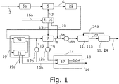
- the proposed method is for the production of ammonia 1, wherein this preparation is carried out by synthesis in a manner known per se from the prior art. Specifically, the proposed method by the in the Fig. 1 illustrated proposed plant for the production of ammonia 1 executed.
- the proposed plant has according to the representation of Fig. 1 an oxygen recovery arrangement 4 for providing an oxygen stream 3, a synthesis gas reactor arrangement 5 for obtaining a synthesis gas stream 6, which comprises hydrogen and carbon oxides, from a carbon-containing energy carrier stream 2 and the oxygen stream 3 and an adsorption device 7 for separating the synthesis gas stream 6 into a hydrogen stream 8 having hydrogen and into a purge stream 9.
- the proposed plant further comprises an ammonia reactor assembly 11 for converting the hydrogen stream 8 and a nitrogen stream 10 into ammonia 1.
- the proposed plant is characterized in that the plant has a recovery device 12 for recovering a hydrogen-containing recovery stream 13 and a waste gas stream 14 to be discharged from the purge stream 9.
- the hydrogen of the recovery stream 13 is at least partially supplied to the ammonia reactor assembly 11 for conversion into ammonia 1.
- the carbonaceous energy carrier stream 2 and the oxygen stream 3 from the oxygen recovery arrangement 4 are fed to the synthesis gas reactor arrangement 5 in the proposed process.
- the carbonaceous energy carrier stream 2 may be a natural gas stream comprising methane, water, hydrogen sulfide, ethane, propane and optionally lower levels of butane. Likewise, it may be a stream of associated gas or an oil stream.
- the oxygen stream 3 comprises oxygen, preferably at a molar fraction of at least 80%. Likewise, it may be that the oxygen stream 3 consists of oxygen and nitrogen or alternatively consists essentially of oxygen.
- a pretreatment of the energy carrier stream 2 can take place, for example by feeding to a - also in the Fig. 1 shown - Desulfurization 5a or to a - not shown here - Pre-reforming. These are preferably also included in the proposed plant.
- the synthesis gas reactor arrangement 5 is set up to recover the synthesis gas stream 6 with hydrogen and carbon oxides.
- a conversion of the hydrocarbons into hydrogen and carbon oxides-that is, into carbon monoxide and carbon dioxide-takes place in a manner known per se from the prior art.
- the synthesis gas stream 6 of the adsorption device 7 for separating the synthesis gas stream 6 in the hydrogen-containing hydrogen stream 8 and fed into the purge stream 9.
- the synthesis gas stream 6 can be treated in various ways, which will be described in more detail below. It may also be the case that the purge stream 9 consists essentially of the constituents of the synthesis gas stream 6 minus the hydrogen stream 8, except for a purge stream 15 which may be fed in, described in more detail below.
- the hydrogen stream 8 and a nitrogen stream 10 of the ammonia reactor assembly 11 is fed and converted there into ammonia 1.
- the nitrogen stream 10 it is preferable that it consists essentially of nitrogen.
- the hydrogen stream 8 is combined with the nitrogen stream 10 to form a feed stream 8a and this feed stream 8a is fed to a feed compressor 8b for compressing the feed stream 8a before the hydrogen stream 8 and the nitrogen stream 10 brought together with it are fed as feed stream 8a to the ammonia reactor arrangement 11 become.
- the proposed system includes the feed compressor 8b.
- the proposed method is characterized in that the purge stream 9 is fed to the recovery device 12, which extracts the hydrogenous recycle stream 13 from the purge stream 9 and removes the offgas stream 14 and the hydrogen of the recycle stream 13 at least partially the ammonia reactor assembly 11 for conversion into ammonia 1 is supplied.
- the hydrogen of the recovery stream 13 is substantially completely supplied to the ammonia reactor assembly 11 for conversion into ammonia 1.
- the recovery stream 13 from the recovery device 12 need not be supplied directly to the ammonia reactor assembly 11 or be merged directly with the hydrogen stream 8 or the feed stream 8a. Rather, the supply of the hydrogen of the recovery stream 13 to the ammonia reactor assembly 11 can also be effected indirectly, which will be described in more detail below.
- the recovery stream 13 may also have a molar hydrogen content corresponding to the syngas stream 6 or even a lower molar hydrogen content.
- the synthesis gas reactor arrangement 5 recover the synthesis gas stream 6 from the energy carrier stream 2 by an autothermal reforming with the oxygen stream 3 so that a catalytic partial oxidation provides the heat required for the endothermic reforming reactions. These are therefore the autothermal reforming known per se from the prior art, which is also referred to as catalytic partial oxidation.
- the synthesis gas stream 6 exits the synthesis gas reactor arrangement 5 with an outlet pressure of at least 70 bar, preferably from 75 bar to 80 bar. In the present exemplary embodiment, the synthesis gas stream 6 exits the synthesis gas reactor arrangement 5 at a pressure of 72 bar and at a temperature of 1025 ° C.
- the synthesis gas stream 6 has a total mass flow of 522,393 kg / h and respective molar proportions of substantially 6% carbon dioxide, 16% carbon monoxide, 44% hydrogen, 1% methane, 32% water and less than 1% nitrogen.
- This high outlet pressure is made possible by an original pressure of the energy carrier stream 2 of more than 78 bar and the lack of need for a - not required here - steam reforming to reduce the pressure.
- This autothermal reforming can thus - especially in contrast to conventional steam reforming - higher pressures of the synthesis gas stream 6 can be achieved, which not only leads to a lower or even completely unnecessary compressor power before the ammonia reactor assembly 11, but also - as will be described below - for the possibly necessary regeneration in the recovery device 12 is advantageous.
- a preferred embodiment of each of the proposed method and the proposed plant is characterized in that the adsorption device 7 comprises a plurality of containers with an adsorbent.
- the containers can each be operated alternately in one of several phases.
- the adsorption device 7 for Pressure swing adsorption is arranged and is alternately performed in at least one of the plurality of containers in a Adsorptionsphase at higher pressure of the synthesis gas stream 6 for recovering the hydrogen stream 8 and from at least one other of the plurality of containers in a purge phase at lower pressure of the purge stream 9 is omitted ,
- This is the principle known per se from the prior art of a PSA.
- some of the containers of the adsorption device 7 are operated in the adsorption phase in which the syngas stream 6 is subjected to adsorption while other containers of the adsorption device 7 in the rinsing phase are cleaned of the adsorbed substances.
- the adsorption device 7 By operating the containers of the adsorption device 7 in respectively different, alternating phases, both the adsorption and the rinsing can take place continuously as a whole.
- the adsorbent comprises a molecular sieve for separating hydrogen.
- the higher pressure of the adsorption phase is achieved by a compression of the synthesis gas stream 6 in the adsorption device 7.
- the synthesis gas stream 6 - including the recovery stream 13 - at a pressure of substantially 65.5 bar and at a temperature of 20 ° C to the adsorber 7 and has at a mass flow of 105.767 kg / h respective molar fractions of im Substantially 3% carbon dioxide, 1% carbon monoxide, 91% hydrogen, 4% methane and 1% nitrogen. It can be seen that the proportion of hydrogen is very high even before being fed to the adsorption device 7, which leads to its discharge.
- the hydrogen stream 8 from the adsorption device 7 then has a mass flow of 41,175 kg / h at 43 ° C and a pressure of 64.9 bar and consists essentially completely of hydrogen.
- a further preferred embodiment of each of the proposed method and the proposed plant is characterized in that the adsorption device 7 is adapted for temperature swing adsorption and alternately in at least one of the plurality of containers in a Adsorptionsphase at lower temperature of the synthesis gas stream 6 for obtaining the Hydrogen stream 8 is passed and is discharged from at least one other of the plurality of containers in a purge phase at a higher temperature of the purge stream 9.
- TSA temperature change adsorption
- This operation according to the temperature swing adsorption can also be combined with the pressure swing adsorption described above.
- the higher temperature is achieved by a heat exchange with a warmer fluid and / or the lower temperature by a heat exchange with a colder fluid.
- the recovery stream 13 of the adsorption device 7 is fed upstream of the synthesis gas stream 6 in terms of process technology. This fact is also in the Fig. 1 shown. In any case, a portion of the hydrogen in the recovery stream 13 then passes into the hydrogen stream 8 and with this on to the ammonia reactor assembly 11.
- This upstream supply makes it possible that no special demands on the purity of the recovery stream 13 must be made because impurities and inert in the repeated passage through the adsorption 7 are separated. This freedom in turn can be crucial for the selection and the economy of the recovery process used.
- the recovery stream 13 of the adsorption device 7 downstream of the process is fed to the hydrogen stream 8, optionally with the nitrogen stream 10. In other words, then neither the recovery stream 13 nor hydrogen from the recovery stream 13 passes through the adsorption device 7 before it is fed to the ammonia reactor assembly 11.
- the recovery stream 13 has in the present embodiment, a mass flow of a total of 20,800 kg / h at a temperature of 40 ° C and a pressure of 72 bar.
- the respective molar portions of the recovery stream 13 are essentially 10% carbon dioxide, 3% carbon monoxide, 66% hydrogen and 4% nitrogen.
- the purge stream 9 has a total mass flow of 63,592 kg / h at a temperature of 40 ° C and a pressure of 1.5 bar with a respective molar fraction of essentially 19% carbon dioxide, 7% carbon monoxide, 36% hydrogen, 28% methane and 10% nitrogen.
- the recovery device 12 not only can the recovery device 12 be supplied to the purge stream 9, but other gas streams can also be supplied to it.
- the recirculation of the recovery stream 13 upstream of the adsorption device 7 also passes through the adsorption device 7. It may also be the case that the recycle stream 13 is fed directly to the adsorption device 7 and recycled in this way. This also leads to a passage through the adsorption device 7 through the recovery stream 13 with the corresponding hydrogen, but without an intermediate step of supplying the synthesis gas stream 6.
- recovery stream 13 - that is, a plurality of recovery streams - is recovered from the recovery device 12, then for each of these recovery streams 13 independently one of the possibilities described above, the hydrogen of the respective recovery stream 13 at least partially the ammonia reactor assembly 11 for conversion into ammonia 1 supply.
- a preferred embodiment of each of the proposed method and the proposed plant is characterized in that for obtaining the purge stream 9, a nitrogen-containing, preferably consisting essentially of nitrogen, purge stream 15 of the adsorption 7 is supplied.
- a nitrogen-containing, preferably consisting essentially of nitrogen, purge stream 15 of the adsorption 7 is supplied.
- the purge stream 15 for purge of the purge stream 9 is fed to the at least one other of the plurality of containers in the rinsing phase. While the majority of the purge stream 15 used leaves the adsorption device 7 with the purge stream 9, a smaller part remains after the purge in the adsorption 7 and leaves it with the hydrogen stream 8.
- the hydrogen stream 8 contains a small amount of nitrogen, but for the downstream ammonia reactor assembly 11 is not disturbing and even desirable because it reduces the nitrogen stream 10 to be added.
- the hydrogen stream it is preferred that it has a molar fraction of at least 90% hydrogen and preferably at least 95% hydrogen. It can also have a molar fraction of at least 99% hydrogen.
- the hydrogen stream 8 essentially consists of hydrogen and of the purge stream 15 remaining in the adsorption device 7 nitrogen. Alternatively, it may also be that the hydrogen stream 8 consists essentially of hydrogen.
- the purge stream 9 corresponds in the case of a nitrogen-containing purge stream 15 in its composition to the amount of nitrogen remaining in the hydrogen stream 8 reduced purge stream 15 with the leached out of the adsorber 7 substance, which in turn the synthesis gas stream 6 minus the hydrogen stream 8 and optionally a directly Adsorption 7 supplied recovery stream 13 - as described above - corresponds.
- the nitrogen of this purge stream 15 can originate from any source. It is preferred that the purge stream 15 is recovered from an air separation unit 16 for recovering nitrogen and oxygen from an ambient air 16a and supplied to the adsorption device 7.
- the proposed plant preferably comprises this air separation unit 16.
- Such an air separation unit 16 can provide several material streams for the proposed method and for the proposed plant.
- the nitrogen stream 10 is provided by the air separation unit 16.
- the purge flow 15 has a lower pressure than the nitrogen flow 10.
- the oxygen recovery device 4 includes or consists of the air separation unit 16. In this case, the oxygen flow 3 is also provided by the air separation unit 16.
- a further preferred embodiment which in the Fig.1 is represented, is characterized in that the recovery device 12, a membrane device 17 for separating the recovery stream 13 from the purge gas 9, whereby the exhaust gas flow 14 remains.
- the separation of the recovery stream 13 through the membrane device 17 causes the remainder of the purge stream 9 to become the exhaust stream 14.
- part of the exhaust gas stream 14 is used as a membrane rinse stream 18 for rinsing out the recovery stream 13.
- a process technology of the recovery device 12 upstream purge gas compressor 12a which is preferably included in the proposed plant, for compressing the purge gas 9
- a process technology of the recovery device 12 downstream recovery compressor 12b which is preferably also included in the proposed plant, be used to compress the recovery stream 13.
- Such a membrane device 17 is particularly well suited to be combined with a purge stream 15 consisting essentially of nitrogen for the adsorption device 7, since such a membrane device 17 can be operated without problem in the purge stream 9 with high nitrogen contents.
- the recovery device 12 has a further adsorption device, which is arranged for separating the purge stream 9 in the recovery stream 13 and the exhaust gas stream 14. It is thus to a certain extent a sequential arrangement of adsorption devices and in particular PSAs. Accordingly, this further adsorption device is preferably set up for pressure swing adsorption and / or for temperature change adsorption.
- a plurality of containers of the further adsorption device are operated in the adsorption phase and in the purge phase at lower pressure than the plurality of containers of the adsorption device 7 respectively in the adsorption phase and in the purge phase.
- the synthesis gas stream 6 of a carbon dioxide scrubbing 19 is supplied to wash at least a portion of the carbon dioxide from the synthesis gas stream 6.
- this carbon dioxide scrubber 19, which may also be referred to as a carbon dioxide scrubber, is included in the proposed plant.
- at least part of the carbon dioxide can be washed out of the synthesis gas stream 6 in this carbon dioxide wash 19 in any desired manner.
- the carbon dioxide is washed out by a washing medium comprising methanol.
- the carbon dioxide is substantially completely washed out of the syngas stream 6 by the carbon dioxide scrubber 19.
- the carbon dioxide scrubber 19 discharges a carbon dioxide-containing stream 19a, which preferably substantially comprises the scrubbed carbon dioxide.
- the synthesis gas stream 6 is fed to an absorption stage 20 of the carbon dioxide scrubbing 19 for receiving the carbon dioxide in the scrubbing medium and that the scrubbing medium in the absorption stage 20 and in a regeneration stage 21 of the carbon dioxide scrubbing 19 for releasing carbon dioxide from the scrubbing medium in a Cycle is driven.
- the operation of such a laundry device is known per se from the prior art.
- the washing medium comprises cold methanol and in this way is conducted in a so-called cold methanol cycle, which is also referred to as "cold methanol loop". Accordingly, it is preferable that a temperature of the washing medium in the carbon dioxide scrubbing is continuously lower than -10 ° C. In the regeneration step 21, even lower temperatures are regularly reached, for example between -60 ° C and -80 ° C. It may also be that the temperature of the washing medium in the carbon dioxide scrubbing is consistently less than -20 ° C or even less than - 30 ° C. The corresponding pressure ratios of the washing medium will be described below.
- the carbon dioxide is released from the washing medium in the regeneration stage 21 substantially by pressure release of the washing medium.
- the carbon dioxide-containing stream 19a can be recovered.
- the carbon dioxide released from the washing medium in the regeneration stage 21 without heating becomes.
- the carbon dioxide can certainly be heated, for example to a temperature range between 0 ° C. and 20 ° C. by heat exchange with hot synthesis gas to be cooled.
- Fig. 1 the carbon dioxide scrubbing 19 is followed by an adsorption device 7 for pressure swing adsorption and thus the removal of carbon oxides, methane and other inert, so that the residual carbon dioxide remaining after the carbon dioxide scrubbing 19 in the synthesis gas stream 6 is effectively removed there.
- Such a regeneration essentially by pressure release, is particularly well possible, in particular, when the synthesis gas stream 6 is passed through the carbon dioxide scrubber 19 at as high a pressure as possible.
- the provision of autothermal reforming in the synthesis gas reactor arrangement 5 makes it possible to provide the synthesis gas stream 6 with an outlet pressure of at least 70 bar.
- washing medium is pumped in the circulation supply from the regeneration stage 21 to the absorption stage 20 to a higher pressure. This corresponds to the opposite process to the pressure relief described above.
- the drastic cooling of the washing medium taking place during the pressure release is a desired and characteristic effect of the cold methanol cycle. It causes the regenerated and recycled washing medium the carbon dioxide can resume extremely efficient, so that the total carbon dioxide scrubbing very compact and the required amount of washing medium can be very small.
- Fig. 1 has the carbon dioxide scrubbing 19 and especially the absorption stage 20 supplied synthesis gas stream 6 with a mass flow of 407.780 kg / h at a temperature of 40 ° C and a pressure of 67.5 bar a respective molar fraction of essentially 26% carbon dioxide, 1% carbon monoxide , 70% hydrogen, 2% methane and 1% nitrogen. Accordingly, it is preferred that the synthesis gas stream 6 of the carbon dioxide scrubbing 19 is supplied at a pressure of at least 30 bar, at least 40 bar, at least 50 bar, at least 60 bar or at least 65 bar.
- the pressure of the washing medium in the absorption stage 20 essentially corresponds to the above-described pressure of the synthesis gas stream 6 in the carbon dioxide scrubbing 19.
- the pressure of the scrubbing medium can substantially drop to atmospheric pressure or even to a vacuum.
- the release of the carbon dioxide in the regeneration stage 21 is multi-stage, so that the carbon dioxide scrubbing 19 - and especially the regeneration stage 21 - a carbon dioxide-containing stream 19a and a hydrogen-containing stream 19b emits, preferably the hydrogen-containing stream 19b has substantially washed out hydrogen.
- This fact can also be expressed by the fact that a molar carbon dioxide content of the carbon dioxide-containing stream 19a is greater than that of the hydrogenous stream 19b. It can also be stated that a molar hydrogen content of the hydrogen-containing stream 19b is greater than that of the carbon dioxide-containing stream 19a.
- the carbon dioxide scrubbing 19 the hydrogenous stream 19b by a first pressure release of the washing medium in the regeneration stage 21 and the carbon dioxide-containing stream 19a by a second pressure release of the washing medium in the regeneration stage 21 deliver.
- the carbon dioxide-containing stream 19a has a mass flow of 305,372 kg / h at a temperature of 40 ° C and a pressure of 1.5 bar and a molar fraction of 99% carbon dioxide.
- the hydrogen-containing stream 19b which is supplied to the recovery device 12 described above, has a mass flow of 14,654 kg / h at a temperature of 45 ° C and a pressure of 7 bar.
- the hydrogen-containing stream 19b also has a molar fraction of essentially 60% carbon dioxide, 1% carbon monoxide, 31% hydrogen, 6% methane and 2% argon. Recognizable, therefore, the proportion of hydrogen is not negligible, which can then be used by feeding to the recovery device 12.
- a preferred embodiment of each of the proposed method and the proposed plant is characterized in that the synthesis gas stream 6 a shift device 22 is supplied, that the shift device 22 supplied synthesis gas stream 6 has water and that in the shift device 22, a water gas shift reaction to implement at least a portion of the carbon monoxide of the synthesis gas stream 6 takes place with the water in carbon dioxide and hydrogen.
- the shift device 22 is included in the proposed plant. This feed to the shift device 22 of the carbon dioxide scrubbing 19 preferably takes place upstream of the process, which is also the case in the Fig. 1 is shown.
- the water in the synthesis gas stream 6 may on the one hand already be present in the energy carrier stream 2.
- the synthesis gas stream 6 can also be supplied to the synthesis gas stream 6 in a saturation (not shown here).
- a saturation for the synthesis of ammonia from the energy carrier stream 2 only hydrogen - in addition to the possibly existing nitrogen - interesting, so that the carbon oxides in the synthesis gas stream 6 advantageously as far as possible before being fed to the adsorber 7 can be removed from this.
- additionally valuable hydrogen is recovered by the water gas shift reaction carried out in the shift device 22 and on the other hand carbon dioxide is recovered at the expense of carbon monoxide.
- the synthesis gas stream 6 supplied to the adsorption device 7 only has a small proportion of carbon oxides, so that the load on the adsorption device 7 is low.
- the synthesis gas stream 6 between the synthesis gas reactor arrangement 5 and the adsorption 7 further, not separately shown or described process stages go through, in particular those for changing the temperature or the water or water vapor content.
- the synthesis gas stream 6 fed to the shift device 22 has a mass flow of 522,393 kg / h at a temperature of 320 ° C. and a pressure of 71.5 bar.
- the synthesis gas stream 6 has a molar fraction of essentially 6% carbon dioxide, 16% carbon monoxide, 44% hydrogen, 1% methane, 1% nitrogen and 32% water.
- the synthesis gas stream 6 obtained from the shift device 22 - which has already been subjected to the above water gas shift reaction - then has a mass flow of 522,397 kg / h at a temperature of 355 ° C. and a pressure of 69 bar.
- the ammonia reactor assembly 11 has a reactor stage 11a for ammonia synthesis and a process technology of the reactor stage 11a downstream condensation stage 24 for separating ammonia 1 from residual gas 24a. Then, the ammonia 1 synthesized in the reactor stage 11 is first passed out of the reactor stage 11a as crude ammonia stream 23 and fed to the condensation stage 24, from which the ammonia 1 is recovered by condensation. Remaining residual gas 24a is as shown in the Fig. 1 recycled from the condensation stage 24 to the reactor stage 11a.
- a cooling of the condensation stage 24 with the carbon dioxide scrubbing 19 for cooling the scrubbing medium to one in the Fig. 1 not shown manner is coupled.
Landscapes
- Chemical & Material Sciences (AREA)
- Organic Chemistry (AREA)
- Chemical Kinetics & Catalysis (AREA)
- Inorganic Chemistry (AREA)
- Engineering & Computer Science (AREA)
- Combustion & Propulsion (AREA)
- Health & Medical Sciences (AREA)
- General Health & Medical Sciences (AREA)
- Analytical Chemistry (AREA)
- Separation Of Gases By Adsorption (AREA)
- Hydrogen, Water And Hydrids (AREA)
Abstract
Description
- Die Erfindung betrifft ein Verfahren zur Herstellung von Ammoniak mit den Merkmalen des Oberbegriffs von Anspruch 1 sowie eine Anlage zur Herstellung von Ammoniak mit den Merkmalen des Oberbegriffs von Anspruch 15.
- Die Ammoniaksynthese geht von Wasserstoff sowie Stickstoff als Ausgangsstoffen aus, wobei speziell der Wasserstoff regelmäßig durch Synthesegas bereitgestellt wird, welches Synthesegas insbesondere durch Reformierung aus einem kohlenstoffhaltigen Energieträgerstrom wie z. B. Erdgas gewonnen wurde.
- Das Gewinnen des Wasserstoffs auf eine solche Art und Weise bringt es jedoch mit sich, dass das Synthesegas eine Vielzahl von anderen Stoffen aufweist, welche für die Ammoniaksynthese zunächst keine Rolle spielen bzw. sogar für den entsprechenden Katalysator schädlich sind. Zu diesen nicht erwünschten Stoffen zählen u.a. Methan aber auch Argon und Helium, wobei die Kohlenstoffoxide dem Katalysator sogar schaden. Da bei der Ammoniaksynthese das Gasgemisch mit dem Wasserstoff und dem Stickstoff regelmäßig in einem Kreislauf gefahren wird, aus welchem durch Kondensation flüssiger Ammoniak entnommen wird, erfolgt selbst bei einem vollständigen Entfernen der Kohlenstofloxide grundsätzlich eine Anreicherung der anderen Stoffe in dem Kreislauf, welche Anreicherung der Ammoniaksynthese abträglich ist und welche es erforderlich macht, diese unerwünschten Stoffe ebenfalls im Kreislauf zu fahren. Dies führt insbesondere durch die erforderliche größere Dimensionierung der relevanten Komponenten auch zu einer Erhöhung der mit der Ammoniaksynthese verbundenen Kosten.
- Ein Ansatz zur Begrenzung der oben beschriebenen Anreicherung und zur Verringerung der Konzentration der obigen Inertstoffe besteht darin, einen Teil des im Kreislauf gefahrenen Gases auszuschleusen. Sowohl für die Verringerung einer Konzentration der obigen Inertstoffe wie Methan im Kreislauf als auch zum Verhindern eines Verlustes des ausgeschleusten Wasserstoffs und Stickstoffs für die Ammoniaksynthese - was zu einem Sinken der Ammoniakproduktion führen würde - ist dann eine Rückgewinnung von Wasserstoff und/oder Stickstoff aus dem ausgeschleusten Gas erforderlich. Ein solches Ausschleusen und die Rückgewinnen von Wasserstoff und/oder Stickstoff erfordert aber regelmäßig eine Abtrennung und Rückverdichtung des rückgewonnenen Gases, wobei beide Prozessschritte hinsichtlich des apparativen Aufwands, der Energie und damit der Kosten aufwändig sind.
- Die
DE 10 2015 210 801 A1 wiederum schlägt einen Ansatz vor, welcher ganz ohne ein solches Ausschleusen aus dem Kreislauf der Ammoniaksynthese auskommen soll. Und zwar soll eine Abtrennung von Stoffen wie Methan, Wasser, Argon und/oder von Kohlenstoffoxiden aus dem Gasgemisch mit Wasserstoff und Stickstoff erfolgen, bevor dieses Gasgemisch der Ammoniaksynthese zugeführt wird. - An diesem Ansatz ist wiederum nachteilig, dass zwar entweder eine große Reinheit des Gasgemisches erreicht werden kann, etwa durch das Vorsehen einer Vorrichtung zur Druckwechsel-Adsorption (PSA) zur Reinigung, dies aber zu empfindlichen Verlusten an sich für die Synthese wertvollem Wasserstoff führt. Hinzu kommen Beschränkungen bei der Auslegung der PSA bezüglich der zugeführten Menge an zugeführtem Gas und des Drucks, bei dem sie betrieben wird. Wird andererseits eine Abtrennung eingesetzt, welche zu einer geringeren Reinheit führt, so wird das Problem der Inertstoffe nicht ausreichend abgemildert um eine Ausschleusung im Kreislauf der Ammoniaksynthese vollständig entbehrlich zu machen.
- Ausgehend von diesem Stand der Technik besteht daher die Aufgabe der Erfindung darin, auch bei der großvolumigen Herstellung von Ammoniak ein für die Ammoniaksynthese geeignetes Gas und insbesondere den Wasserstoff dieses Gases auf wirtschaftlichere Art und Weise bereitzustellen.
- Bezogen auf ein Verfahren zur Herstellung von Ammoniak gemäß dem Oberbegriff von Anspruch 1 wird diese Aufgabe durch die Merkmale des kennzeichnenden Teils von Anspruch 1 gelöst. Bezogen auf eine Anlage zur Synthese von Ammoniak gemäß dem Oberbegriff von Anspruch 15 wird diese Aufgabe durch die Merkmale des kennzeichnenden Teils von Anspruch 15 gelöst.
- Der Erfindung liegt die Erkenntnis zugrunde, dass bei Verwendung einer Adsorptionsvorrichtung - wie z. B. einer PSA - zum Gewinnen von weitgehend reinem Wasserstoff aus einem Synthesegasstrom der Verlust an Wasserstoff dadurch begrenzt werden kann, dass der Abgasstrom aus der Adsorptionsvorrichtung mit dem Wasserstoff im Abgasstrom einer Rückgewinnungsvorrichtung zugeführt werden kann, aus der der Wasserstoff zumindest teilweise zurückgewonnen wird. Zwar bedeutet dies prinzipiell das Vorsehen einer - gegenüber dem Ansatz aus dem Stand der Technik - zusätzlichen Vorrichtung, doch hat sich herausgestellt, dass dieser Mehraufwand durch den Vorteil der Begrenzung des Wasserstoffverlusts mehr als kompensiert wird.
- Die Unteransprüche 2 und 3 beschreiben bevorzugte Ausgestaltungen der Adsorptionsvorrichtung zum Abtrennen des Wasserstoffstroms aus dem Synthesegasstrom, wobei hier insbesondere eine Druckwechsel-Adsorption, aber auch eine Kombination von Druckwechsel- und Temperaturwechsel-Adsorption vorgesehen werden kann.
- Der aus der Rückgewinnungsvorrichtung gewonnene Rückgewinnungsstrom kann prozesstechnisch an unterschiedlichen Stellen in den Synthesegasstrom zurückgeführt werden, wobei der Unteranspruch 4 die besonders vorteilhafte Rückführung beschreibt, welche der Adsorptionsvorrichtung prozesstechnisch vorgelagert ist.
- Eine Ausgestaltung der Druckwechsel Adsorption, die eine besonders große Wasserstoffausbeute ermöglicht, bei der also eine besonders geringe Menge Wasserstoff mit dem Purgestrom ausgeschleust wird, ist dann möglich, wenn Stickstoff zum Spülen verwendet wird. Dies ist Gegenstand des Unteranspruchs 5. Wie von Unteranspruch 6 beschrieben, ist ggf. beim Spülen in der Adsorptionsvorrichtung verbleibender Stickstoff nicht nur kein Problem für die Ammoniaksynthese, sondern kann sogar als Ausgangsstoff dienen. Dieser Stickstoff kann gemäß dem Gegenstand des Unteranspruchs 7 von einer Luftzerlegungseinheit bereitgestellt werden.
- Bezüglich der Ausgestaltung der Rückgewinnungsvorrichtung werden in den Unteransprüchen 8 und 9 verschiedene bevorzugte Varianten beschrieben, wobei der Unteranspruchs 8 eine besonders interessante Lösung mit einer Membrananordnung beschreibt, da sie für die Rückgewinnung des Wasserstoffs auch mit einem stickstoffhaltigen Purgestrom besonders gut geeignet ist. Ein solcher ergibt sich, wenn man in der Adsorptionsvorrichtung mit Stickstoff spült. Folglich wird die besonders verlustarme Kombination von Stickstoffspülung und Wasserstoffrückgewinnung in besonders wirtschaftlicher Weise ermöglicht.
- Die Unteransprüche 10 bis 12 beschreiben eine der Adsorptionsvorrichtung vorgelagerte Kohlenstoffdioxidwäsche und deren weitere bevorzugte Ausgestaltung. Insbesondere die Möglichkeit, die Regeneration des in der Kohlenstoffdioxidwäsche verwendeten Absorptionsmediums ohne Erhitzung durchzuführen, bietet einen beachtlichen wirtschaftlichen Vorteil. Diese Erhitzung wird deshalb entbehrlich, weil durch das Vorsehen der nachgelagerten Adsorptionsvorrichtung keine übermäßige Reinheit bei der Kohlenstoffdioxidwäsche erreicht werden muss.
- Diese Kohlenstoffdioxidwäsche wird dadurch noch nützlicher, dass - wie im Unteranspruch 13 beschrieben - der Kohlenstoffdioxidwäsche ein Wassergas-Shift vorgelagert wird. Der für die oben beschriebene Regeneration des verwendeten Absorptionsmediums ohne Erhitzung nützliche hohe Druck des Synthesegases kann insbesondere dann gewährleistet werden, wenn das Synthesegas ohne eine herkömmliche Dampfreformierung sondern durch eine autotherme Reformierung hergestellt wird. Dies wird im Unteranspruch 14 beschrieben.
- Weitere Einzelheiten, Merkmale, Ausgestaltungen, Ziele und Vorteile der vorliegenden Erfindung werden nachfolgend anhand der lediglich ein Ausführungsbeispiel wiedergebenden Zeichnung erläutert. In der Zeichnung zeigt
- Fig. 1
- schematisch das Fließbild einer Anlage zur Ausführung eines Ausführungsbeispiels des vorschlagsgemäßen Verfahrens.
- Das vorschlagsgemäße Verfahren dient der Herstellung von Ammoniak 1, wobei diese Herstellung durch Synthese in an sich aus dem Stand der Technik bekannter Weise erfolgt. Speziell wird das vorschlagsgemäße Verfahren durch die in der
Fig. 1 dargestellte vorschlagsgemäße Anlage zur Herstellung von Ammoniak 1 ausgeführt. - Die vorschlagsgemäße Anlage weist gemäß der Darstellung der
Fig. 1 eine Sauerstoffgewinnungsanordnung 4 zum Bereitstellen eines Sauerstoffstroms 3, eine Synthesegasreaktoranordnung 5 zum Gewinnen eines Synthesegasstroms 6, welcher Wasserstoff und Kohlenstoffoxide aufweist, aus einem kohlenstoffhaltigen Energieträgerstrom 2 und dem Sauerstoffstrom 3 und eine Adsorptionsvorrichtung 7 zum Trennen des Synthesegasstroms 6 in einen Wasserstoff aufweisenden Wasserstoffstrom 8 und in einen Purgestrom 9 auf. Die vorschlagsgemäße Anlage weist ferner eine Ammoniak-Reaktoranordnung 11 zum Umwandeln des Wasserstoffstroms 8 und eines Stickstoffstroms 10 in Ammoniak 1 auf. - Die vorschlagsgemäße Anlage ist dadurch gekennzeichnet, dass die Anlage eine Rückgewinnungsvorrichtung 12 zum Gewinnen eines wasserstoffhaltigen Rückgewinnungsstroms 13 sowie eines abzuführenden Abgasstroms 14 aus dem Purgestrom 9 aufweist. Vorschlagsgemäß wird der Wasserstoff des Rückgewinnungsstroms 13 zumindest teilweise der Ammoniak-Reaktoranordnung 11 zur Umwandlung in Ammoniak 1 zugeführt.
- Entsprechend zu der vorschlagsgemäßen Anlage wird bei dem vorschlagsgemäßen Verfahren der kohlenstoffhaltige Energieträgerstrom 2 und der Sauerstoffstrom 3 aus der Sauerstoffgewinnungsanordnung 4 der Synthesegasreaktoranordnung 5 zugeführt. Bei dem kohlenstoffhaltigen Energieträgerstrom 2 kann es sich um einen Erdgasstrom umfassend Methan, Wasser, Schwefelwasserstoff, Ethan, Propan und ggf. geringere Anteile von Butan handeln. Ebenso kann es sich um einen Strom von Erdölbegleitgas oder auch um einen Erdölstrom handeln. Der Sauerstoffstrom 3 umfasst Sauerstoff, vorzugweise zu einem molaren Anteil von mindestens 80 %. Ebenso kann es sein, dass der Sauerstoffstrom 3 aus Sauerstoff und Stickstoff besteht oder alternativ im Wesentlichen aus Sauerstoff besteht. Vor der Zuführung zur Synthesegasreaktoranordnung 5 kann auch eine Vorbehandlung des Energieträgerstroms 2 stattfinden, beispielsweise durch Zuführung zu einer - ebenfalls in der
Fig. 1 dargestellten - Entschwefelungsvorrichtung 5a oder zu einem - hier nicht dargestellten - Pre-Reforming. Diese sind vorzugsweise ebenfalls von der vorschlagsgemäßen Anlage umfasst sind. - Bei dem vorschlagsgemäßen Verfahren ist die Synthesegasreaktoranordnung 5 zum Gewinnen des Synthesegasstroms 6 mit Wasserstoff und Kohlenstoffoxiden eingerichtet. Dabei findet in der Synthesegasreaktoranordnung 5 eine Umwandlung der Kohlenwasserstoffe in Wasserstoff und Kohlenstoffoxide - also in Kohlenstoffmonoxid und Kohlenstoffdioxid - in an sich aus dem Stand der Technik bekannter Weise statt.
- Weiter wird beim vorschlagsgemäßen Verfahren und entsprechend der Darstellung in der
Fig. 1 der Synthesegasstrom 6 der Adsorptionsvorrichtung 7 zum Trennen des Synthesegasstroms 6 in den Wasserstoff aufweisenden Wasserstoffstrom 8 und in den Purgestrom 9 zugeführt. Vor Zuführung zu der Adsorptionsvorrichtung 7 kann der Synthesegasstrom 6 auf verschiedene Art und Weise behandelt werden, was untenstehend ausführlicher beschrieben wird. Ebenso kann es sein, dass der Purgestrom 9 bis auf einen ggf. zugeführten, unten noch näher beschriebenen Spülstrom 15 im Wesentlichen aus den Bestandteilen des Synthesegasstroms 6 abzüglich des Wasserstoffstroms 8 besteht. - Beim vorschlagsgemäßen Verfahren wird der Wasserstoffstrom 8 sowie ein Stickstoffstrom 10 der Ammoniak-Reaktoranordnung 11 zugeführt und dort in Ammoniak 1 umgewandelt. Bezüglich des Stickstoffstroms 10 ist bevorzugt, dass dieser im Wesentlichen aus Stickstoff besteht. Bevorzugt ist weiter, dass gemäß der Darstellung in der
Fig. 1 der Wasserstoffstrom 8 mit dem Stickstoffstrom 10 zu einem Speisestrom 8a zusammengeführt wird und dieser Speisestrom 8a einem Speise-Kompressor 8b zum Verdichten des Speisestroms 8a zugeführt wird, bevor der Wasserstoffstrom 8 und der mit ihm zusammengeführte Stickstoffstrom 10 als Speisestrom 8a der Ammoniak-Reaktoranordnung 11 zugeführt werden. Vorzugsweise umfasst die vorschlagsgemäße Anlage den Speise-Kompressor 8b. - Das vorschlagsgemäße Verfahren ist dadurch gekennzeichnet, dass der Purgestrom 9 der Rückgewinnungsvorrichtung 12 zugeführt wird, welche aus dem Purgestrom 9 den wasserstoffhaltigen Rückgewinnungsstrom 13 gewinnt sowie den Abgasstrom 14 abführt und dass der Wasserstoff des Rückgewinnungsstroms 13 zumindest teilweise der Ammoniak-Reaktoranordnung 11 zur Umwandlung in Ammoniak 1 zugeführt wird. Bevorzugt wird der Wasserstoff des Rückgewinnungsstroms 13 im Wesentlichen vollständig der Ammoniak-Reaktoranordnung 11 zur Umwandlung in Ammoniak 1 zugeführt. Dabei muss der Rückgewinnungsstrom 13 aus der Rückgewinnungsvorrichtung 12 nicht unmittelbar der Ammoniak-Reaktoranordnung 11 zugeführt werden oder unmittelbar mit dem Wasserstoffstrom 8 oder dem Speisestrom 8a zusammengeführt werden. Vielmehr kann die Zuführung des Wasserstoffs des Rückgewinnungsstroms 13 zur Ammoniak-Reaktoranordnung 11 auch indirekt erfolgen, was untenstehend noch genauer beschrieben wird. Ebenso ist grundsätzlich kein erhöhter oder ausschließlicher Anteil an Wasserstoff im Rückgewinnungsstrom 13 gegenüber dem Synthesegasstrom 6 erforderlich, sodass der Rückgewinnungsstrom 13 auch einen molaren Wasserstoffanteil entsprechend dem Synthesegasstrom 6 oder sogar einen geringeren molaren Wasserstoffanteil aufweisen kann.
- Es ist bevorzugt, dass die Synthesegasreaktoranordnung 5 aus dem Energieträgerstrom 2 den Synthesegasstrom 6 durch eine autotherme Reformierung mit dem Sauerstoffstrom 3 gewinnt, sodass eine katalytische partielle Oxidation die für die endothermen Reformierungsreaktionen erforderliche Wärme bereitstellt. Es handelt sich dabei also um die an sich aus dem Stand der Technik bekannte autotherme Reformierung, welche auch als katalytische partielle Oxidation bezeichnet wird. Hier ist es weiter bevorzugt, dass der Synthesegasstrom 6 aus der Synthesegasreaktoranordnung 5 mit einem Austrittsdruck von mindestens 70 bar, vorzugsweise von 75 bar bis 80 bar austritt. Im vorliegenden Ausführungsbeispiel tritt der Synthesegasstrom 6 mit einem Druck von 72 bar und bei einer Temperatur von 1025° C aus der Synthesegasreaktoranordnung 5 aus. Dabei weist der Synthesegasstrom 6 einen Massenstrom von insgesamt 522.393 kg / h auf und jeweilige molare Anteile von im Wesentlichen 6 % Kohlenstoffdioxid, 16 % Kohlenstoffmonoxid, 44 % Wasserstoff, 1 % Methan, 32 % Wasser sowie weniger als 1 % Stickstoff auf. Dieser hohe Austrittsdruck wird durch einen ursprünglichen Druck des Energieträgerstroms 2 von mehr als 78 bar und der fehlenden Notwendigkeit ermöglicht, für eine - hier nicht erforderliche - Dampfreformierung den Druck zu verringern.
- Durch diese autotherme Reformierung können also - insbesondere im Gegensatz zur herkömmlichen Dampfreformierung - höhere Drücke des Synthesegasstroms 6 erreicht werden, was nicht nur zu einer geringeren oder sogar komplett entbehrlichen Kompressorleistung vor der Ammoniak-Reaktoranordnung 11 führt, sondern auch - wie untenstehend noch beschrieben wird - für die ggf. erforderliche Regeneration bei der Rückgewinnungsvorrichtung 12 von Vorteil ist.
- Eine bevorzugte Ausführungsform jeweils des vorschlagsgemäßen Verfahrens und der vorschlagsgemäßen Anlage ist dadurch gekennzeichnet, dass die Adsorptionsvorrichtung 7 eine Vielzahl von Behältern mit einem Adsorbens aufweist. Dabei können die Behälter jeweils abwechselnd in einem von mehreren Phasen betrieben werden. So ist es bevorzugt, dass die Adsorptionsvorrichtung 7 zur Druckwechsel-Adsorption eingerichtet ist und abwechselnd in mindestens einem der Vielzahl von Behältern in einer Adsorptionsphase bei höherem Druck der Synthesegasstrom 6 zum Gewinnen des Wasserstoffstroms 8 geführt wird und aus mindestens einem anderen der Vielzahl von Behältern in einer Spülphase bei niedrigerem Druck der Purgestrom 9 ausgelassen wird. Es handelt sich dabei um das an sich aus dem Stand der Technik bekannte Prinzip einer PSA. Mit anderen Worten werden zu einem beliebigen Zeitpunkt einige der Behälter der Adsorptionsvorrichtung 7 in der Adsorptionsphase betrieben, in welcher der Synthesegasstrom 6 der Adsorption unterzogen wird, während gleichzeitige andere Behälter der Adsorptionsvorrichtung 7 in der Spülphase von den adsorbierten Stoffen gereinigt werden. Indem die Behälter der Adsorptionsvorrichtung 7 in jeweils unterschiedlichen, abwechselnden Phasen betrieben werden, kann sowohl die Adsorption als auch das Spülen insgesamt kontinuierlich erfolgen. Dabei kann es auch weitere Phasen als die beschriebene Adsorptionsphase und Spülphase geben. Bevorzugt ist weiter, dass das Adsorbens einen Molekularsieb zum Trennen von Wasserstoff aufweist. Es kann weiter sein, dass der höhere Druck der Adsorptionsphase durch eine Komprimierung des Synthesegasstroms 6 in der Adsorptionsvorrichtung 7 erreicht wird. Im in der
Fig. 1 dargestellten Ausführungsbeispiel gelangt der Synthesegasstrom 6 - einschließlich des Rückgewinnungsstroms 13 - bei einem Druck von im Wesentlichen 65,5 bar und mit einer Temperatur von 20° C zu der Adsorptionsvorrichtung 7 und weist bei einem Massenstrom von insgesamt 105.767 kg / h jeweilige molare Anteile von im Wesentlichen 3 % Kohlenstoffdioxid, 1 % Kohlenstoffmonoxid, 91 % Wasserstoff, 4 % Methan und 1 % Stickstoff auf. Erkennbar ist der Anteil des Wasserstoffs bereits vor Zuführung zur Adsorptionsvorrichtung 7 sehr hoch, was zu deren Entlastung führt. Die für die Änderung der Zusammensetzung des Synthesegasstroms 6 wesentlichen Vorgänge werden untenstehend näher beschrieben. Der Wasserstoffstrom 8 aus der Adsorptionsvorrichtung 7 weist dann einen Massenstrom von insgesamt 41.175 kg / h bei 43° C auf und einem Druck von 64,9 bar und besteht im Wesentlichen vollständig aus Wasserstoff. - Eine weitere bevorzugte Ausführungsform jeweils des vorschlagsgemäßen Verfahrens und der vorschlagsgemäßen Anlage ist dadurch gekennzeichnet, dass die Adsorptionsvorrichtung 7 zur Temperaturwechsel-Adsorption eingerichtet ist und abwechselnd in mindestens einem der Vielzahl von Behältern in einer Adsorptionsphase bei niedrigerer Temperatur der Synthesegasstrom 6 zum Gewinnen des Wasserstoffstroms 8 geführt wird und aus mindestens einem anderen der Vielzahl von Behältern in einer Spülphase bei höherer Temperatur der Purgestrom 9 ausgelassen wird. Hier handelt es sich um das ebenfalls prinzipiell aus dem Stand der Technik bekannte Prinzip einer Temperaturwechsel-Adsorption (TSA). Diese Funktionsweise gemäß der Temperaturwechsel-Adsorption kann auch mit der oben beschriebenen Druckwechsel-Adsorption kombiniert werden. Hier kann es sein, dass die höhere Temperatur durch einen Wärmeaustausch mit einem wärmeren Fluid und/oder die niedrigere Temperatur durch einen Wärmeaustausch mit einen kälteren Fluid erreicht wird.
- Gemäß einer bevorzugten Ausführungsform jeweils des vorschlagsgemäßen Verfahrens und der vorschlagsgemäßen Vorrichtung ist vorgesehen, dass der Rückgewinnungsstrom 13 der Adsorptionsvorrichtung 7 prozesstechnisch vorgelagert dem Synthesegasstrom 6 zugeführt wird. Dieser Sachverhalt ist auch in der
Fig. 1 dargestellt. Jedenfalls ein Teil des Wasserstoffs im Rückgewinnungsstrom 13 gelangt dann in den Wasserstoffstrom 8 und mit diesem weiter zur Ammoniak-Reaktoranordnung 11. Diese vorgelagerte Zuführung ermöglicht es weiter, dass keine besonderen Anforderungen an die Reinheit des Rückgewinnungsstroms 13 gestellt werden müssen, da Verunreinigungen und Inerte beim abermaligen Durchlaufen der Adsorptionsvorrichtung 7 abgetrennt werden. Diese Freiheit wiederum kann entscheidend für die Auswahl und die Wirtschaftlichkeit des eingesetzten Rückgewinnungsverfahrens sein. Es kann aber auch sein, dass der Rückgewinnungsstrom 13 der Adsorptionsvorrichtung 7 prozesstechnisch nachgelagert dem Wasserstoffstrom 8, ggf. mit dem Stickstoffstrom 10, zugeführt wird. Mit anderen Worten durchläuft dann weder der Rückgewinnungsstrom 13 noch Wasserstoff aus dem Rückgewinnungsstrom 13 die Adsorptionsvorrichtung 7 bevor er der Ammoniak-Reaktoranordnung 11 zugeführt wird. - Der Rückgewinnungsstrom 13 weist im vorliegenden Ausführungsbeispiel einen Massenstrom von insgesamt 20.800 kg / h bei einer Temperatur von 40 ° C und einem Druck von 72 bar auf. Die jeweiligen molaren Anteile des Rückgewinnungsstroms 13 sind im Wesentlichen 10 % Kohlenstoffdioxid, 3 % Kohlenstoffmonoxid, 66 % Wasserstoff und 4 % Stickstoff. Im Vergleich dazu weist der Purgestrom 9 einen Massenstrom von insgesamt 63.592 kg / h bei einer Temperatur von 40 ° C und einem Druck von 1,5 bar mit einem jeweiligen molaren Anteil von im Wesentlichen 19 % Kohlenstoffdioxid, 7 % Kohlenstoffmonoxid, 36 % Wasserstoff, 28 % Methan sowie 10 % Stickstoff auf. Wie untenstehend noch beschrieben wird, kann der Rückgewinnungsvorrichtung 12 nicht nur der Purgestrom 9 zugeführt werden, sondern es können ihr auch andere Gasströme zugeführt werden.
- Wie bereits festgestellt, durchläuft in dem dargestellten Fall der der Adsorptionsvorrichtung 7 vorgelagerten Rückführung der Rückgewinnungsstrom 13 mit dem entsprechenden Wasserstoff auch wieder die Adsorptionsvorrichtung 7. Ebenso kann es sein, dass der Rückgewinnungsstrom 13 der Adsorptionsvorrichtung insbesondere direkt zugeführt 7 und auf diese Weise rezykliert wird. Auch dies führt zu einem Durchlaufen der Adsorptionsvorrichtung 7 durch den Rückgewinnungsstrom 13 mit dem entsprechenden Wasserstoff, jedoch ohne Zwischenschritt der Zuführung zum Synthesegasstrom 6.
- Schließlich kann es auch sein, dass aus der Rückgewinnungsvorrichtung 12 mehr als ein Rückgewinnungsstrom 13 - also eine Vielzahl von Rückgewinnungsströmen - gewonnen wird, wobei dann für jeden dieser Rückgewinnungsströme 13 unabhängig voneinander eine der oben beschriebenen Möglichkeiten besteht, den Wasserstoff des jeweiligen Rückgewinnungsstroms 13 zumindest teilweise der Ammoniak-Reaktoranordnung 11 zur Umwandlung in Ammoniak 1 zuzuführen.
- Eine bevorzugte Ausführungsform jeweils des vorschlagsgemäßen Verfahrens und der vorschlagsgemäßen Anlage ist dadurch gekennzeichnet, dass zum Gewinnen des Purgestroms 9 ein stickstoffhaltiger, vorzugsweise im Wesentlichen aus Stickstoff bestehender, Spülstrom 15 der Adsorptionsvorrichtung 7 zugeführt wird. Gegenüber einem herkömmlichen, im Wesentlichen aus Wasserstoff bestehenden Spülstrom hat dies den Vorteil, dass die Verluste an Wasserstoff durch den Spülvorgang deutlich verringert werden. Hier kann es insbesondere sein, dass dem mindestens einem anderen der Vielzahl von Behältern in der Spülphase der Spülstrom 15 zum Ausspülen des Purgestroms 9 zugeführt wird. Während der größte Teil des eingesetzten Spülstroms 15 die Adsorptionsvorrichtung 7 mit dem Purgestrom 9 verlässt, verbleibt ein geringerer Teil nach dem Spülvorgang in der Adsorptionsvorrichtung 7 und verlässt sie mit dem Wasserstoffstrom 8. Mithin enthält der Wasserstoffstrom 8 einen geringen Anteil an Stickstoff, der aber für die nachgeschaltete Ammoniak-Reaktoranordnung 11 nicht störend ist und sondern sogar wünschenswert ist, da er den zuzusetzenden Stickstoffstrom 10 verringert.
- Entsprechend ist es bezüglich des Wasserstoffstroms bevorzugt, dass er einen molaren Anteil von mindestens 90 % Wasserstoff und vorzugsweise von mindestens 95 % Wasserstoff aufweist. Er kann auch einen molaren Anteil von mindestens 99 % Wasserstoff aufweisen. Ebenso kann es sein, dass der Wasserstoffstrom 8 im Wesentlichen aus Wasserstoff und aus vom Spülstrom 15 in der Adsorptionsvorrichtung 7 verbliebenem Stickstoff besteht. Alternativ kann es aber auch sein, dass der Wasserstoffstrom 8 im Wesentlichen aus Wasserstoff besteht.
- Der Purgestrom 9 entspricht bei einem stickstoffhaltigen Spülstrom 15 in seiner Zusammensetzung dem um die Menge des im Wasserstoffstrom 8 verbleibenden Stickstoffs reduzierten Spülstrom 15 mit dem aus der Adsorptionsvorrichtung 7 ausgespülten Stoff, welcher Stoff wiederum dem Synthesegasstroms 6 abzüglich des Wasserstoffstroms 8 und ggf. einem direkt der Adsorptionsvorrichtung 7 zugeführten Rückgewinnungsstrom 13 - wie oben beschrieben - entspricht.
- Grundsätzlich kann der Stickstoff dieses Spülstroms 15 einer beliebigen Quelle entstammen. Bevorzugt ist, dass der Spülstrom 15 aus einer Luftzerlegungseinheit 16 zum Gewinnen von Stickstoff und Sauerstoff aus einer Umgebungsluft 16a gewonnen und der Adsorptionsvorrichtung 7 zugeführt wird. Vorzugsweise umfasst die vorschlagsgemäße Anlage diese Luftzerlegungseinheit 16. Eine solche Luftzerlegungseinheit 16 kann mehrere Stoffströme für das vorschlagsgemäße Verfahren und für die vorschlagsgemäße Anlage bereitstellen. So ist es weiter bevorzugt, dass der Stickstoffstrom 10 von der Luftzerlegungseinheit 16 bereitgestellt wird. In diesem Fall ist es bevorzugt, dass der Spülstrom 15 einen niedrigeren Druck als der Stickstoffstrom 10 aufweist. Ferner ist es bevorzugt, dass die Sauerstoffgewinnungsanordnung 4 die Luftzerlegungseinheit 16 umfasst oder aus ihr besteht. In diesem Fall wird auch der Sauerstoffstrom 3 von der Luftzerlegungseinheit 16 bereitgestellt.
- Eine weitere bevorzugte Ausführungsform, welche in der
Fig.1 dargestellt ist, ist dadurch gekennzeichnet, dass die Rückgewinnungsvorrichtung 12 eine Membranvorrichtung 17 zum Abtrennen des Rückgewinnungsstroms 13 aus dem Purgestrom 9 aufweist, wodurch der Abgasstrom 14 verbleibt. Mit anderen Worten führt das Abtrennen des Rückgewinnungsstroms 13 durch die Membranvorrichtung 17 dazu, dass der Rest des Purgestroms 9 zum Abgasstrom 14 wird. Wie ebenfalls in derFig. 1 dargestellt ist es hier weiter bevorzugt, dass ein Teil des Abgasstroms 14 als Membranspülstrom 18 zum Ausspülen des Rückgewinnungsstroms 13 verwendet wird. Wie ebenfalls in derFig. 1 dargestellt, kann ein prozesstechnisch der Rückgewinnungsvorrichtung 12 vorgelagerter Purgegas-Kompressor 12a, welcher vorzugsweise von der vorschlagsgemäßen Anlage umfasst ist, zum Komprimieren des Purgegases 9 sowie ein prozesstechnisch der Rückgewinnungsvorrichtung 12 nachgelagerter Rückgewinnungs-Kompressor 12b, weicher vorzugsweise ebenfalls von der vorschlagsgemäßen Anlage umfasst ist, zum Komprimieren des Rückgewinnungsstroms 13 verwendet werden. - Eine solche Membranvorrichtung 17 ist besonders gut dazu geeignet, mit einem im Wesentlichen aus Stickstoff bestehenden Spülstrom 15 für die Adsorptionsvorrichtung 7 kombiniert zu werden, da eine solche Membranvorrichtung 17 problemlos mit hohen Stickstoffanteilen im Purgestrom 9 betrieben werden kann.
- Es gibt auch Alternativen zu einer Rückgewinnungsvorrichtung 12 mit einer Membranvorrichtung 17. Gemäß einer bevorzugten, hier nicht dargestellten Ausführungsform ist vorgesehen, dass die Rückgewinnungsvorrichtung 12 eine weitere Adsorptionsvorrichtung aufweist, welche zum Trennen des Purgestroms 9 in den Rückgewinnungsstrom 13 und den Abgasstrom 14 eingerichtet ist. Es handelt sich also gewissermaßen um eine sequenzielle Anordnung von Adsorptionsvorrichtungen und insbesondere PSAs. Entsprechend ist vorzugsweise diese weitere Adsorptionsvorrichtung zur Druckwechsel-Adsorption und/oder zur Temperaturwechsel-Adsorption eingerichtet. Im Vergleich mit der Adsorptionsvorrichtung 7 kann es sein, dass eine Vielzahl von Behältern der weiteren Adsorptionsvorrichtung jeweils in der Adsorptionsphase und in der Spülphase bei niedrigerem Druck betrieben werden als die Vielzahl von Behältern der Adsorptionsvorrichtung 7 jeweils in der Adsorptionsphase und in der Spülphase.
- Gemäß einer bevorzugten Ausführungsform jeweils des vorschlagsgemäßen Verfahrens und der vorschlagsgemäßen Anlage ist vorgesehen, dass der Synthesegasstrom 6 einer Kohlenstoffdioxidwäsche 19 zum Auswaschen mindestens eines Teiles des Kohlenstoffdioxids aus dem Synthesegasstrom 6 zugeführt wird. Vorzugsweise ist diese Kohlenstoffdioxidwäsche 19, welche ebenso als Vorrichtung zur Kohlenstoffdioxidwäsche bezeichnet werden kann, von der vorschlagsgemäßen Anlage umfasst. Grundsätzlich kann in dieser Kohlenstoffdioxidwäsche 19 auf beliebige Art und Weise mindestens ein Teil des Kohlenstoffdioxids aus dem Synthesegasstrom 6 ausgewaschen werden. Bevorzugt ist jedoch, dass in der Kohlenstoffdioxidwäsche 19 das Kohlenstoffdioxid durch ein Methanol umfassendes Waschmedium ausgewaschen wird. Ebenso ist es bevorzugt, dass das Kohlenstoffdioxid im Wesentlichen vollständig durch die Kohlenstoffdioxidwäsche 19 aus dem Synthesegasstrom 6 ausgewaschen wird. Vorzugsweise gibt die Kohlenstoffdioxidwäsche 19 einen kohlenstoffdioxidhaltigen Strom 19a ab, welcher vorzugsweise im Wesentlichen das ausgewaschene Kohlenstoffdioxid aufweist.
- Hier ist es ebenso bevorzugt, dass der Synthesegasstrom 6 einer Absorptionsstufe 20 der Kohlenstoffdioxidwäsche 19 zur Aufnahme des Kohlenstoffdioxids in das Waschmedium zugeführt wird und dass das Waschmedium in der Absorptionsstufe 20 sowie in einer Regenerationsstufe 21 der Kohlenstoffdioxidwäsche 19 zum Freisetzen von Kohlenstoffdioxid aus dem Waschmedium in einem Kreislauf gefahren wird. Die Funktionsweise einer solchen Wäschervorrichtung ist an sich aus dem Stand der Technik bekannt.
- Besonders vorteilhaft ist es, wenn das Waschmedium kaltes Methanol umfasst und auf diese Weise in einem sogenannten Kaltmethanol-Kreislauf geführt wird, was auch als "cold methanol loop" bezeichnet wird. Entsprechend ist es bevorzugt, dass eine Temperatur des Waschmediums in der Kohlenstoffdioxidwäsche durchgehend weniger als -10 ° C beträgt. Dabei werden in der Regenerationsstufe 21 regelmäßig noch tiefere Temperaturen erreicht, so etwa zwischen -60° C und -80° C. Weiter kann es sein, dass die Temperatur des Waschmediums in der Kohlenstoffdioxidwäsche durchgehend weniger als -20° C oder sogar weniger als -30° C beträgt. Die entsprechenden Druckverhältnisse des Waschmediums werden untenstehend beschrieben.
- Bevorzugt ist hier vorgesehen, dass das Kohlenstoffdioxid aus dem Waschmedium in der Regenerationsstufe 21 im Wesentlichen durch Druckentspannung des Waschmediums freigesetzt wird. So kann der kohlenstoffdioxidhaltige Strom 19a gewonnen werden. Insbesondere ist es bevorzugt, dass das Kohlenstoffdioxid aus dem Waschmedium in der Regenerationsstufe 21 erhitzungsfrei freigesetzt wird. Auf diese Weise entfällt eine Erhitzung zwecks Regeneration, für welche Erhitzung üblicherweise ein aufwendiger separater Anlagenteil - als Heißregenerator bezeichnet - vorgesehen werden muss. Dies wiederum verringert den apparativen Aufwand und den Energiebedarf der Kohlenstoffdioxidwäsche 19, was kennzeichnend für den Ansatz des Kaltmethanol-Kreislaufs ist. Nach erfolgter erhitzungsfreier Freisetzung des Kohlenstoffdioxids aus dem Waschmedium kann demgegenüber durchaus eine Erwärmung des Kohlenstoffdioxids erfolgen, so etwa auf einen Temperaturbereich zwischen 0° C und 20° C durch einen Wärmeaustausch mit abzukühlendem heißen Synthesegas.
- Vorteilhaft für den Einsatz einer solchen Regeneration praktisch ausschließlich durch Druckentspannung sind geringe Anforderungen an den zu erzielenden Restgehalt - molarer Anteil - an Kohlenstoffdioxid im der Adsorptionsvorrichtung 7 zugeführten Synthesegasstrom 6, welcher molare Anteil im Bereich zwischen 0,2% und 3%, vorzugsweise zwischen 1% und 2% liegt. Vorliegend ist gemäß
Fig. 1 der Kohlenstoffdioxidwäsche 19 eine Adsorptionsvorrichtung 7 zur Druckwechsel-Adsorption und damit zur Entfernung von Kohlenstoffoxiden, Methan und anderen Inerten nachgeschaltet, sodass das nach der Kohlenstoffdioxidwäsche 19 im Synthesegasstrom 6 verbleibende, restliche Kohlenstoffdioxid dort effektiv entfernt wird. - Eine solche Regeneration im Wesentlichen durch Druckentspannung ist insbesondere dann besonders gut möglich, wenn der Synthesegasstrom 6 mit einem möglichst hohen Druck durch die Kohlenstoffdioxidwäsche 19 geführt wird. Wie oben bereits beschrieben wurde, erlaubt es das Vorsehen einer autothermen Reformierung in der Synthesegasreaktoranordnung 5, den Synthesegasstrom 6 mit einem Austrittdruck von mindestens 70 bar bereitzustellen.
- Weiter ist es in diesem Zusammenhang bevorzugt, dass das Waschmedium bei der Kreislaufzufuhr von der Regenerationsstufe 21 zur Absorptionsstufe 20 auf einen höheren Druck gepumpt wird. Dies entspricht dem zur oben beschriebenen Druckentspannung entgegengesetzten Vorgang.
- Die bei der Druckentspannung erfolgende drastische Abkühlung des Waschmediums ist ein gewünschter und kennzeichnender Effekt des Kaltmethanol-Kreislaufs. Sie führt dazu, dass das regenerierte und zurückgeführte Waschmedium das Kohlenstoffdioxid äußerst effizient wieder aufnehmen kann, so dass die Kohlendioxidwäsche insgesamt sehr kompakt ausfallen und die benötigte Menge an Waschmedium sehr klein sein kann.
- Im vorliegenden Ausführungsbeispiel der
Fig. 1 weist der der Kohlenstoffdioxidwäsche 19 und speziell der Absorptionsstufe 20 zugeführte Synthesegasstrom 6 mit einem Massenstrom von 407.780 kg / h bei einer Temperatur von 40° C und einem Druck von 67,5 bar einen jeweiligen molaren Anteil von im Wesentlichen 26 % Kohlenstoffdioxid, 1 % Kohlenstoffmonoxid, 70 % Wasserstoff, 2 % Methan und 1 % Stickstoff auf. Entsprechend ist es bevorzugt, dass der Synthesegasstrom 6 der Kohlenstoffdioxidwäsche 19 mit einem Druck von jeweils mindestens 30 bar, von mindestens 40 bar, von mindestens 50 bar, von mindestens 60 bar oder von mindestens 65 bar zugeführt wird. Dabei entspricht der Druck des Waschmediums in der Absorptionsstufe 20 im Wesentlichen dem oben beschriebenen Druck des Synthesegasstroms 6 in der Kohlenstoffdioxidwäsche 19. In der Regenerationsstufe 21 kann der Druck des Waschmediums im Wesentlichen bis auf Atmosphärendruck oder sogar bis auf ein Vakuum absinken. - Bevorzugt ist, dass in Übereinstimmung mit dem in der
Fig. 1 dargestellten Ausführungsbeispiel, dass die Abgabe des Kohlenstoffdioxids in der Regenerationsstufe 21 mehrstufig erfolgt, sodass die Kohlenstoffdioxidwäsche 19 - und speziell die Regenerationsstufe 21 - einen kohlenstoffdioxidhaltigen Strom 19a sowie einen wasserstoffhaltigen Strom 19b abgibt, wobei vorzugsweise der wasserstoffhaltige Strom 19b im Wesentlichen ausgewaschenen Wasserstoff aufweist. Dieser Sachverhalt lässt sich auch dadurch ausdrücken, dass ein molarer Kohlenstoffdioxidanteil des kohlenstoffdioxidhaltigen Stroms 19a größer ist als derjenige des wasserstoffhaltigen Stroms 19b. Ebenso lässt sich feststellen, dass ein molarer Wasserstoffanteil des wasserstoffhaltigen Stroms 19b größer ist als derjenige des kohlenstoffdioxidhaltigen Stroms 19a. - Bei einem Auswaschen von Kohlenstoffdioxid werden regelmäßig auch andere Bestandteile des gewaschenen Gasstroms, so etwa auch Wasserstoff, mit ausgewaschen. Die verschiedenen ausgewaschenen Gase werden aber bei der obigen Druckentspannung des Waschmediums hauptsächlich bei unterschiedlichen Druckentspannungsstufen freigesetzt. Folglich kann, wie im Ausführungsbeispiel gemäß der
Fig. 1 , die Kohlenstoffdioxidwäsche 19 den wasserstoffhaltigen Strom 19b durch eine erste Druckentspannung des Waschmediums in der Regenerationsstufe 21 und den kohlenstoffdioxidhaltigen Strom 19a durch eine zweite Druckentspannung des Waschmediums in der Regenerationsstufe 21 abgeben. Gemäß dem vorliegenden Ausführungsbeispiel weist der kohlenstoffdioxidhaltige Strom 19a einen Massenstrom von 305.372 kg / h bei einer Temperatur von 40 ° C und einem Druck von 1,5 bar sowie einen molaren Anteil von 99 % Kohlenstoffdioxid auf. Der wasserstoffhaltige Strom 19b hingegen, welcher der oben beschriebenen Rückgewinnungsvorrichtung 12 zugeführt wird, weist einen Massenstrom von 14.654 kg / h bei einer Temperatur von 45 ° C und einem Druck von 7 bar auf. Der wasserstoffhaltige Strom 19b weist ferner einen molaren Anteil von im Wesentlichen 60 % Kohlenstoffdioxid, 1 % Kohlenstoffmonoxid, 31 % Wasserstoff, 6 % Methan sowie 2 % Argon auf. Erkennbar ist also der Anteil an Wasserstoff nicht unerheblich, welcher dann also durch Zuführung zur Rückgewinnungsvorrichtung 12 genutzt werden kann. - Eine bevorzugte Ausführungsform jeweils des vorschlagsgemäßen Verfahrens und der vorschlagsgemäßen Anlage ist dadurch gekennzeichnet, dass der Synthesegasstrom 6 einer Shiftvorrichtung 22 zugeführt wird, dass der der Shiftvorrichtung 22 zugeführte Synthesegasstrom 6 Wasser aufweist und dass in der Shiftvorrichtung 22 eine Wassergas-Shift-Reaktion zur Umsetzung zumindest eines Teils des Kohlenstoffmonoxids des Synthesegasstroms 6 mit dem Wasser in Kohlenstoffdioxid und Wasserstoff stattfindet. Vorzugsweise ist die Shiftvorrichtung 22 von der vorschlagsgemäßen Anlage umfasst. Bevorzugt erfolgt diese Zuführung zur Shiftvorrichtung 22 der Kohlenstoffdioxidwäsche 19 prozesstechnisch vorgelagert, was so auch in der
Fig. 1 dargestellt ist. Das Wasser im Synthesegasstrom 6 kann einerseits bereits im Energieträgerstrom 2 vorhanden sein. Es kann andererseits auch in einer - hier nicht dargestellten - Sättigung dem Synthesegasstrom 6 zugeführt werden. Für die Ammoniaksynthese ist aus dem Energieträgerstrom 2 nur Wasserstoff - neben dem ggf. vorhandenen Stickstoff - interessant, sodass die Kohlenstoffoxide im Synthesegasstrom 6 vorteilhafterweise möglichst weitgehend bereits vor Zuführung zur Adsorptionsvorrichtung 7 aus diesem entfernt werden können. Durch die in der Shiftvorrichtung 22 durchgeführte Wassergas-Shift-Reaktion wird einerseits zusätzlich wertvoller Wasserstoff gewonnen und anderseits Kohlenstoffdioxid auf Kosten von Kohlenstoffmonoxid gewonnen. Durch die Kombination mit der obigen Kohlenstoffdioxidwäsche 19 wird also zuerst in der Shiftvorrichtung 22 - unter dem Gewinn von Wasserstoff - die Zusammensetzung der Kohlenstoffoxide im Synthesegasstrom 6 zugunsten des Kohlenstoffdioxids gegenüber dem Kohlenstoffmonoxid verschoben und dann das Kohlenstoffdioxid im Wesentlichen vollständig ausgewaschen. Im Ergebnis weist der der Adsorptionsvorrichtung 7 zugeführte Synthesegasstrom 6 nur noch einen geringen Anteil an Kohlenstoffoxiden auf, sodass die Belastung der Adsorptionsvorrichtung 7 gering ausfällt. Neben der in derFig. 1 dargestellten Shiftvorrichtung 22 und der Kohlenstoffdioxidwäsche 19 kann der Synthesegasstrom 6 zwischen der Synthesegasreaktoranordnung 5 und der Adsorptionsvorrichtung 7 weitere, hier nicht gesondert dargestellte oder beschriebene Prozessstufen durchlaufen, und zwar insbesondere solche zur Änderung der Temperatur oder des Wasser- bzw. Wasserdampfgehalts. - Im Ausführungsbeispiel der
Fig. 1 weist der der Shiftvorrichtung 22 zugeführte Synthesegasstrom 6 einen Massenstrom von 522.393 kg / h bei einer Temperatur von 320° Celsius und einem Druck von 71,5 bar auf. Der Synthesegasstrom 6 weist einen molaren Anteil von im Wesentlichen 6 % Kohlenstoffdioxid, 16 % Kohlenstoffmonoxid, 44 % Wasserstoff, 1 % Methan, 1 % Stickstoff und 32 % Wasser. Der aus der Shiftvorrichtung 22 gewonnene Synthesegasstrom 6 - welcher also der obigen Wassergas-Shift-Reaktion bereits unterzogen wurde - weist dann einen Massenstrom von 522.397 kg / h bei einer Temperatur von 355° C und einem Druck von 69 bar auf. Hinsichtlich seiner Zusammensetzung weist er einen molaren Anteil von nun im Wesentlichen 21 % Kohlenstoffdioxid, 1 % Kohlenstoffmonoxid, 58 % Wasserstoff, 2 % Methan, 1 % Stickstoff sowie 18 % Wasser auf. Der Anteil an Wasserstoff ist also erkennbar um 14 Prozentpunkt und damit mehr als 25 % Prozent angestiegen, wohingegen die Kohlenstoffoxide im Synthesegasstrom 6 nun fast ausschließlich aus Kohlenstoffdioxid bestehen. - Gemäß der Darstellung in der
Fig. 1 kann es gemäß einer bevorzugten Ausführungsform jeweils des vorschlagsgemäßen Verfahrens und der vorschlagsgemäßen Anlage sein, dass die Ammoniak-Reaktoranordnung 11 einen Reaktorstufe 11a für die Ammoniaksynthese sowie eine prozesstechnisch der Reaktorstufe 11a nachgelagerte Kondensationsstufe 24 zum Abtrennen von Ammoniak 1 aus Restgas 24a aufweist. Dann wird der in der Reaktorstufe 11 synthetisierte Ammoniak 1 zunächst als Rohammoniakstrom 23 aus der Reaktorstufe 11a geführt und der Kondensationsstufe 24 zugeführt, aus weicher das Ammoniak 1 durch Auskondensation gewonnen wird. Ein verbliebenes Restgas 24a wird gemäß der Darstellung in derFig. 1 aus der Kondensationsstufe 24 zu der Reaktorstufe 11a rezykliert. Hier ist es weiter bevorzugt, dass eine Kühlung der Kondensationsstufe 24 mit der Kohlenstoffdioxidwäsche 19 zur Kühlung des Waschmediums auf eine in derFig. 1 nicht dargestellte Art und Weise gekoppelt ist. - Vorstehend beschriebene bevorzugte Ausgestaltungen des vorschlagsgemäßen Verfahrens entsprechen bevorzugten Ausgestaltungen der vorschlagsgemäßen Anlage und umgekehrt.
Claims (15)
- Verfahren zur Herstellung von Ammoniak (1), wobei ein kohlenstoffhaltiger Energieträgerstrom (2) und ein Sauerstoffstrom (3) aus einer Sauerstoffgewinnungsanordnung (4) einer Synthesegasreaktoranordnung (5) zum Gewinnen eines Synthesegasstroms (6) mit Wasserstoff und Kohlenstoffoxiden zugeführt wird, wobei der Synthesegasstrom (6) einer Adsorptionsvorrichtung (7) zum Trennen des Synthesegasstroms (6) in einen Wasserstoff aufweisenden Wasserstoffstrom (8) und in einen Purgestrom (9) zugeführt wird und wobei der Wasserstoffstrom (8) sowie ein Stickstoffstrom (10) einer Ammoniak-Reaktoranordnung (11) zugeführt und dort in Ammoniak (1) umgewandelt wird, dadurch gekennzeichnet, dass der Purgestrom (9) einer Rückgewinnungsvorrichtung (12) zugeführt wird, welche aus dem Purgestrom (9) einen wasserstoffhaltigen Rückgewinnungsstrom (13) gewinnt sowie einen Abgasstrom (14) abführt und dass der Wasserstoff des Rückgewinnungsstroms (13) zumindest teilweise der Ammoniak-Reaktoranordnung (11) zur Umwandlung in Ammoniak (1) zugeführt wird.
- Verfahren nach Anspruch 1, dadurch gekennzeichnet, dass die Adsorptionsvorrichtung (7) eine Vielzahl von Behältern mit einem Adsorbens aufweist, vorzugsweise, dass die Adsorptionsvorrichtung zur Druckwechsel-Adsorption eingerichtet ist und abwechselnd in mindestens einem der Vielzahl von Behältern in einer Adsorptionsphase bei höherem Druck der Synthesegasstrom (6) zum Gewinnen des Wasserstoffstroms (8) geführt wird und aus mindestens einem anderen der Vielzahl von Behältern in einer Spülphase bei niedrigerem Druck der Purgestrom (9) ausgelassen wird, insbesondere, dass das Adsorbens einen Molekularsieb zum Trennen von Wasserstoff aufweist.
- Verfahren nach Anspruch 2, dadurch gekennzeichnet, dass die Adsorptionsvorrichtung (7) zur Temperaturwechsel-Adsorption eingerichtet ist und abwechselnd in mindestens einem der Vielzahl von Behältern in einer Adsorptionsphase bei niedrigerer Temperatur der Synthesegasstrom (6) zum Gewinnen des Wasserstoffstroms (8) geführt wird und aus mindestens einem anderen der Vielzahl von Behältern in einer Spülphase bei höherer Temperatur der Purgestrom (9) ausgelassen wird.
- Verfahren nach einem der Ansprüche 1 bis 3, dadurch gekennzeichnet, dass der Rückgewinnungsstrom (13) der Adsorptionsvorrichtung (7) prozesstechnisch vorgelagert dem Synthesegasstrom (6) zugeführt wird.
- Verfahren nach einem der Ansprüche 1 bis 4, dadurch gekennzeichnet, dass zum Gewinnen des Purgestroms (9) ein stickstoffhaltiger, vorzugsweise im Wesentlichen aus Stickstoff bestehender, Spülstrom (15) der Adsorptionsvorrichtung (7) zugeführt wird, insbesondere, dass dem mindestens einen anderen der Vielzahl von Behältern in der Spülphase der Spülstrom zum Ausspülen des Purgestroms (9) zugeführt wird.
- Verfahren nach einem der Ansprüche 1 bis 5, dadurch gekennzeichnet, dass der Wasserstoffstrom (8) einen molaren Anteil von mindestens 90 % Wasserstoff, vorzugsweise von mindestens 95 % Wasserstoff aufweist, insbesondere, dass der Wasserstoffstrom (8) im Wesentlichen aus Wasserstoff und aus vom Spülstrom (15) in der Adsorptionsvorrichtung (7) verbliebenem Stickstoff besteht.
- Verfahren nach Anspruch 5 oder 6, dadurch gekennzeichnet, dass der Spülstrom (15) aus einer Luftzerlegungseinheit (16) zum Gewinnen von Stickstoff und Sauerstoff aus einer Umgebungsluft (16a) gewonnen und der Adsorptionsvorrichtung (7) zugeführt wird, vorzugsweise, dass der Stickstoffstrom (10) von der Luftzerlegungseinheit (16) bereitgestellt wird, insbesondere, dass die Sauerstoffgewinnungsanordnung (4) die Luftzerlegungseinheit (16) umfasst.
- Verfahren nach einem der Ansprüche 1 bis 7, dadurch gekennzeichnet, dass die Rückgewinnungsvorrichtung (12) eine Membranvorrichtung (17) zum Abtrennen des Rückgewinnungsstroms (13) aus dem Purgestrom (9) aufweist, wodurch der Abgasstrom (14) verbleibt, vorzugsweise, dass ein Teil des Abgasstroms (14) als Membranspülstrom (18) zum Ausspülen des Rückgewinnungsstroms (13) verwendet wird.
- Verfahren nach einem der Ansprüche 1 bis 8, dadurch gekennzeichnet, die Rückgewinnungsvorrichtung (12) eine weitere Adsorptionsvorrichtung aufweist, welche zum Trennen des Purgestroms (9) in den Rückgewinnungsstrom (13) und den Abgasstrom (14) eingerichtet ist, vorzugsweise, dass die weitere Adsorptionsvorrichtung zur Druckwechsel-Adsorption und/oder zur Temperaturwechsel-Adsorption eingerichtet ist, insbesondere, dass eine Vielzahl von Behältern der weiteren Adsorptionsvorrichtung jeweils in der Adsorptionsphase und in der Spülphase bei niedrigerem Druck betrieben werden als die Vielzahl von Behältern der Adsorptionsvorrichtung jeweils in der Adsorptionsphase und in der Spülphase.
- Verfahren nach einem der Ansprüche 1 bis 9 dadurch gekennzeichnet, dass der Synthesegasstrom (6) einer Kohlenstoffdioxidwäsche (19) zum Auswaschen mindestens eines Teiles des Kohlenstoffdioxids aus dem Synthesegasstrom (6) zugeführt wird, vorzugsweise, dass in der Kohlenstoffdioxidwäsche (19) das Kohlenstoffdioxid durch ein Methanol umfassendes Waschmedium ausgewaschen wird.
- Verfahren nach Anspruch 10, dadurch gekennzeichnet, dass der Synthesegasstrom (6) einer Absorptionsstufe (20) der Kohlenstoffdioxidwäsche (19) zur Aufnahme des Kohlenstoffdioxids in das Waschmedium zugeführt wird und dass das Waschmedium in der Absorptionsstufe (20) sowie in einer Regenerationsstufe (21) der Kohlenstoffdioxidwäsche (19) zum Freisetzen von Kohlenstoffdioxid aus dem Waschmedium in einem Kreislauf gefahren wird.
- Verfahren nach Anspruch 11, dadurch gekennzeichnet, dass das Kohlenstoffdioxid aus dem Waschmedium in der Regenerationsstufe (21) im Wesentlichen durch Druckentspannung des Waschmediums freigesetzt wird, vorzugsweise, dass das Kohlenstoffdioxid aus dem Waschmedium in der Regenerationsstufe (21) erhitzungsfrei freigesetzt wird, insbesondere, dass das Waschmedium bei der Kreislaufzufuhr von der Regenerationsstufe (21) zur Absorptionsstufe (20) auf einen höheren Druck gepumpt wird.
- Verfahren nach einem der Ansprüche 1 bis 12, dadurch gekennzeichnet, dass der Synthesegasstrom (6), vorzugsweise der Kohlenstoffdioxidwäsche (19) prozesstechnisch vorgelagert, einer Shiftvorrichtung (22) zugeführt wird, dass der der Shiftvorrichtung (22) zugeführte Synthesegasstrom (6) Wasser aufweist und dass in der Shiftvorrichtung (22) eine Wassergas-Shift-Reaktion zur Umsetzung zumindest eines Teils des Kohlenstoffmonoxids des Synthesegasstroms (6) mit dem Wasser in Kohlenstoffdioxid und Wasserstoff stattfindet.
- Verfahren nach einem der Ansprüche 1 bis 13, dadurch gekennzeichnet, dass die Synthesegasreaktoranordnung (5) aus dem Energieträgerstrom (2) den Synthesegasstrom (6) durch eine autotherme Reformierung mit dem Sauerstoffstrom (3) gewinnt, sodass eine katalytische partielle Oxidation die für die endothermen Reformierungsreaktionen erforderliche Wärme bereitstellt, vorzugsweise dass der Synthesegasstrom (6) aus der Synthesegasreaktoranordnung (5) mit einem Austrittsdruck von mindestens 70 bar, vorzugsweise von 75 bar bis 80 bar austritt.
- Anlage zur Herstellung von Ammoniak (1) mit einer Sauerstoffgewinnungsanordnung (4) zum Bereitstellen eines Sauerstoffstroms (3), einer Synthesegasreaktoranordnung (5) zum Gewinnen eines Synthesegasstroms (6) mit Wasserstoff und Kohlenstoffoxiden aus einem kohlenstoffhaltigen Energieträgerstrom (2) und dem Sauerstoffstrom (3), einer Adsorptionsvorrichtung (7) zum Trennen des Synthesegasstroms (6) in einen Wasserstoff aufweisenden Wasserstoffstrom (8) und in einen Purgestrom (9) und einer Ammoniak-Reaktoranordnung (11) zum Umwandeln des Wasserstoffstroms (8) und eines Stickstoffstroms (10) in Ammoniak (1), dadurch gekennzeichnet, dass die Anlage eine Rückgewinnungsvorrichtung (12) zum Gewinnen eines wasserstoffhaltigen Rückgewinnungsstrom (13) sowie eines abzuführenden Abgasstroms (14) aus dem Purgestrom (9) und dass der Wasserstoff des Rückgewinnungsstroms (13) zumindest teilweise der Ammoniak-Reaktoranordnung (11) zum Umwandlung in Ammoniak (1) zugeführt wird.
Priority Applications (5)
| Application Number | Priority Date | Filing Date | Title |
|---|---|---|---|
| DK17170711.0T DK3401280T3 (da) | 2017-05-11 | 2017-05-11 | Fremgangsmåde til fremstilling af ammoniak |
| EP17170711.0A EP3401280B1 (de) | 2017-05-11 | 2017-05-11 | Verfahren zur herstellung von ammoniak |
| PCT/EP2018/062111 WO2018206705A1 (de) | 2017-05-11 | 2018-05-09 | Verfahren zur herstellung von ammoniak |
| US16/499,664 US11560306B2 (en) | 2017-05-11 | 2018-05-09 | Method for producing ammonia |
| CN201880031191.4A CN110914197A (zh) | 2017-05-11 | 2018-05-09 | 生产氨的方法 |
Applications Claiming Priority (1)
| Application Number | Priority Date | Filing Date | Title |
|---|---|---|---|
| EP17170711.0A EP3401280B1 (de) | 2017-05-11 | 2017-05-11 | Verfahren zur herstellung von ammoniak |
Publications (2)
| Publication Number | Publication Date |
|---|---|
| EP3401280A1 true EP3401280A1 (de) | 2018-11-14 |
| EP3401280B1 EP3401280B1 (de) | 2021-12-22 |
Family
ID=58745025
Family Applications (1)
| Application Number | Title | Priority Date | Filing Date |
|---|---|---|---|
| EP17170711.0A Active EP3401280B1 (de) | 2017-05-11 | 2017-05-11 | Verfahren zur herstellung von ammoniak |
Country Status (5)
| Country | Link |
|---|---|
| US (1) | US11560306B2 (de) |
| EP (1) | EP3401280B1 (de) |
| CN (1) | CN110914197A (de) |
| DK (1) | DK3401280T3 (de) |
| WO (1) | WO2018206705A1 (de) |
Cited By (1)
| Publication number | Priority date | Publication date | Assignee | Title |
|---|---|---|---|---|
| CN116639707A (zh) * | 2023-05-24 | 2023-08-25 | 山东福富新材料科技有限公司 | 无碳新能源生态系统 |
Families Citing this family (1)
| Publication number | Priority date | Publication date | Assignee | Title |
|---|---|---|---|---|
| EP4269332A1 (de) * | 2022-04-26 | 2023-11-01 | GasConTec GmbH | Verfahren und anlage zur herstellung von ammoniak |
Citations (6)
| Publication number | Priority date | Publication date | Assignee | Title |
|---|---|---|---|---|
| DE3308305A1 (de) * | 1983-03-09 | 1984-09-13 | Didier Engineering Gmbh, 4300 Essen | Verfahren zur erzeugung von wasserstoff |
| US4553981A (en) * | 1984-02-07 | 1985-11-19 | Union Carbide Corporation | Enhanced hydrogen recovery from effluent gas streams |
| DE4334257A1 (de) * | 1993-10-07 | 1995-04-13 | Linde Ag | Verfahren zum Gewinnen von Ammoniak |
| US20110210292A1 (en) * | 2010-05-18 | 2011-09-01 | Kellogg Brown & Root Llc | Gasification System And Process For Maximizing Production Of Syngas and Syngas-Derived Products |
| US20150191351A1 (en) * | 2012-06-25 | 2015-07-09 | L'Air Liquide, Société Anonyme pour I'Etude et I'Exploitation des Procédés Georges Glaude | Method and installation for the combined production of ammonia synthesis gas and carbon dioxide |
| DE102015210801A1 (de) | 2015-06-12 | 2016-12-15 | Thyssenkrupp Ag | Mehrdruckverfahren zur Herstellung von Ammoniak ohne Anreicherung von Inertgas |
Family Cites Families (7)
| Publication number | Priority date | Publication date | Assignee | Title |
|---|---|---|---|---|
| US4592860A (en) * | 1984-02-07 | 1986-06-03 | Union Carbide Corporation | Process and apparatus for ammonia synthesis gas production |
| EP0194765B1 (de) * | 1985-03-08 | 1991-05-08 | Imperial Chemical Industries Plc | Synthesegas |
| US6818198B2 (en) * | 2002-09-23 | 2004-11-16 | Kellogg Brown & Root, Inc. | Hydrogen enrichment scheme for autothermal reforming |
| US7419648B2 (en) * | 2004-07-16 | 2008-09-02 | Shell Oil Company | Process for the production of hydrogen and carbon dioxide |
| ES2440016T3 (es) * | 2009-08-20 | 2014-01-27 | Saudi Basic Industries Corporation | Procedimiento para la coproducción de metanol y amoníaco |
| DE102012013816A1 (de) * | 2012-07-12 | 2014-01-16 | Linde Aktiengesellschaft | Verfahren und Anlage zur Reinigung von Synthesegas, insbesondere für die Ammoniaksynthese |
| EP2801550A1 (de) * | 2013-05-10 | 2014-11-12 | Ammonia Casale S.A. | Verfahren zur Herstellung von Ammoniaksynthesegas mit Hochtemperaturkonvertierung und niedrigem Dampf-Kohlen-Verhältnis |
-
2017
- 2017-05-11 EP EP17170711.0A patent/EP3401280B1/de active Active
- 2017-05-11 DK DK17170711.0T patent/DK3401280T3/da active
-
2018
- 2018-05-09 CN CN201880031191.4A patent/CN110914197A/zh active Pending
- 2018-05-09 WO PCT/EP2018/062111 patent/WO2018206705A1/de not_active Ceased
- 2018-05-09 US US16/499,664 patent/US11560306B2/en active Active
Patent Citations (6)
| Publication number | Priority date | Publication date | Assignee | Title |
|---|---|---|---|---|
| DE3308305A1 (de) * | 1983-03-09 | 1984-09-13 | Didier Engineering Gmbh, 4300 Essen | Verfahren zur erzeugung von wasserstoff |
| US4553981A (en) * | 1984-02-07 | 1985-11-19 | Union Carbide Corporation | Enhanced hydrogen recovery from effluent gas streams |
| DE4334257A1 (de) * | 1993-10-07 | 1995-04-13 | Linde Ag | Verfahren zum Gewinnen von Ammoniak |
| US20110210292A1 (en) * | 2010-05-18 | 2011-09-01 | Kellogg Brown & Root Llc | Gasification System And Process For Maximizing Production Of Syngas and Syngas-Derived Products |
| US20150191351A1 (en) * | 2012-06-25 | 2015-07-09 | L'Air Liquide, Société Anonyme pour I'Etude et I'Exploitation des Procédés Georges Glaude | Method and installation for the combined production of ammonia synthesis gas and carbon dioxide |
| DE102015210801A1 (de) | 2015-06-12 | 2016-12-15 | Thyssenkrupp Ag | Mehrdruckverfahren zur Herstellung von Ammoniak ohne Anreicherung von Inertgas |
Cited By (1)
| Publication number | Priority date | Publication date | Assignee | Title |
|---|---|---|---|---|
| CN116639707A (zh) * | 2023-05-24 | 2023-08-25 | 山东福富新材料科技有限公司 | 无碳新能源生态系统 |
Also Published As
| Publication number | Publication date |
|---|---|
| EP3401280B1 (de) | 2021-12-22 |
| US20200216312A1 (en) | 2020-07-09 |
| US11560306B2 (en) | 2023-01-24 |
| WO2018206705A1 (de) | 2018-11-15 |
| CN110914197A (zh) | 2020-03-24 |
| DK3401280T3 (da) | 2022-03-21 |
Similar Documents
| Publication | Publication Date | Title |
|---|---|---|
| DE69308678T2 (de) | Herstellung von Wasserstoff und Kohlenoxyd durch partielle Oxydierung von Kohlenwasserstoff | |
| EP3205622B1 (de) | Verfahren zur synthese von methanol | |
| DE68912909T2 (de) | Verfahren zur Herstellung von Nitrilen und Oxiden. | |
| EP3307675B1 (de) | Mehrdruckverfahren zur herstellung von ammoniak | |
| EP3390354B1 (de) | Verfahren zur bereitstellung von kohlendioxid für die synthese von harnstoff | |
| WO2005095313A1 (de) | Koproduktion von methanol und ammoniak aus erdgas | |
| EP3323786B1 (de) | Verfahren zur kombinierten herstellung von methanol und ammoniak | |
| DE19625093A1 (de) | Verfahren zur Gewinnung von Kohlenmonoxid und Wasserstoff | |
| EP3720815B1 (de) | Verfahren zur bereitstellung von co2 für die harnstoffsynthese aus rauch- und synthesegas | |
| WO2023208926A1 (de) | Verfahren und anlage zur herstellung von ammoniak | |
| EP3102309B1 (de) | Verfahren zur herstellung höhermolekularer verbindungen aus synthesegas unter verwendung eines indirekt beheizten co2-tsa | |
| EP3969433A1 (de) | Verfahren und anlage zur synthese von methanol | |
| EP1698607B1 (de) | Verfahren zur Adsorberregenerierung | |
| EP3401280B1 (de) | Verfahren zur herstellung von ammoniak | |
| EP3744416B1 (de) | Verfahren und anlage zur synthese von methanol | |
| EP3466869B1 (de) | Verfahren zur kombinierten herstellung von methanol und von ammoniak | |
| DE4210638A1 (de) | Verfahren zur gewinnung von hochreinem wasserstoff und hochreinem kohlenmonoxid | |
| EP1975123A2 (de) | Verfahren und Vorrichtung zur Erzeugung von Synthesegas | |
| EP4066921A1 (de) | Verfahren und anlage zum herstellen von methanol und ammoniak | |
| DE2911669A1 (de) | Verfahren zur erzeugung von wasserstoff | |
| DE10229750B4 (de) | Anlageneinheit und Verfahren zur Desorption von Kohlendioxid aus Methanol | |
| EP4192804B1 (de) | Vorrichtung und verfahren zur herstellung von methanol aus kohlendioxid | |
| DE102019115388A1 (de) | Verfahren und Anlage zur Gewinnung eines Olefins | |
| EP3674261B1 (de) | Verfahren zur synthese einer wasserstoffhaltigen verbindung | |
| EP3333123B1 (de) | Verfahren und anlage zur erzeugung von synthesegas |
Legal Events
| Date | Code | Title | Description |
|---|---|---|---|
| PUAI | Public reference made under article 153(3) epc to a published international application that has entered the european phase |
Free format text: ORIGINAL CODE: 0009012 |
|
| STAA | Information on the status of an ep patent application or granted ep patent |
Free format text: STATUS: THE APPLICATION HAS BEEN PUBLISHED |
|
| AK | Designated contracting states |
Kind code of ref document: A1 Designated state(s): AL AT BE BG CH CY CZ DE DK EE ES FI FR GB GR HR HU IE IS IT LI LT LU LV MC MK MT NL NO PL PT RO RS SE SI SK SM TR |
|
| AX | Request for extension of the european patent |
Extension state: BA ME |
|
| STAA | Information on the status of an ep patent application or granted ep patent |
Free format text: STATUS: REQUEST FOR EXAMINATION WAS MADE |
|
| RAP1 | Party data changed (applicant data changed or rights of an application transferred) |
Owner name: GASCONTEC GMBH |
|
| RIN1 | Information on inventor provided before grant (corrected) |
Inventor name: WAGNER, ULRICH Inventor name: MUELLER, DIERK Inventor name: KOSS, ULRICH |
|
| 17P | Request for examination filed |
Effective date: 20190514 |
|
| RBV | Designated contracting states (corrected) |
Designated state(s): AL AT BE BG CH CY CZ DE DK EE ES FI FR GB GR HR HU IE IS IT LI LT LU LV MC MK MT NL NO PL PT RO RS SE SI SK SM TR |
|
| STAA | Information on the status of an ep patent application or granted ep patent |
Free format text: STATUS: EXAMINATION IS IN PROGRESS |
|
| 17Q | First examination report despatched |
Effective date: 20200113 |
|
| GRAP | Despatch of communication of intention to grant a patent |
Free format text: ORIGINAL CODE: EPIDOSNIGR1 |
|
| STAA | Information on the status of an ep patent application or granted ep patent |
Free format text: STATUS: GRANT OF PATENT IS INTENDED |
|
| INTG | Intention to grant announced |
Effective date: 20210729 |
|
| GRAS | Grant fee paid |
Free format text: ORIGINAL CODE: EPIDOSNIGR3 |
|
| GRAA | (expected) grant |
Free format text: ORIGINAL CODE: 0009210 |
|
| STAA | Information on the status of an ep patent application or granted ep patent |
Free format text: STATUS: THE PATENT HAS BEEN GRANTED |
|
| AK | Designated contracting states |
Kind code of ref document: B1 Designated state(s): AL AT BE BG CH CY CZ DE DK EE ES FI FR GB GR HR HU IE IS IT LI LT LU LV MC MK MT NL NO PL PT RO RS SE SI SK SM TR |
|
| REG | Reference to a national code |
Ref country code: GB Ref legal event code: FG4D Free format text: NOT ENGLISH |
|
| REG | Reference to a national code |
Ref country code: CH Ref legal event code: EP |
|
| REG | Reference to a national code |
Ref country code: DE Ref legal event code: R096 Ref document number: 502017012275 Country of ref document: DE |
|
| REG | Reference to a national code |
Ref country code: AT Ref legal event code: REF Ref document number: 1456959 Country of ref document: AT Kind code of ref document: T Effective date: 20220115 |
|
| REG | Reference to a national code |
Ref country code: IE Ref legal event code: FG4D Free format text: LANGUAGE OF EP DOCUMENT: GERMAN |
|
| REG | Reference to a national code |
Ref country code: DK Ref legal event code: T3 Effective date: 20220316 |
|
| REG | Reference to a national code |
Ref country code: LT Ref legal event code: MG9D |
|
| PG25 | Lapsed in a contracting state [announced via postgrant information from national office to epo] |
Ref country code: RS Free format text: LAPSE BECAUSE OF FAILURE TO SUBMIT A TRANSLATION OF THE DESCRIPTION OR TO PAY THE FEE WITHIN THE PRESCRIBED TIME-LIMIT Effective date: 20211222 Ref country code: LT Free format text: LAPSE BECAUSE OF FAILURE TO SUBMIT A TRANSLATION OF THE DESCRIPTION OR TO PAY THE FEE WITHIN THE PRESCRIBED TIME-LIMIT Effective date: 20211222 Ref country code: FI Free format text: LAPSE BECAUSE OF FAILURE TO SUBMIT A TRANSLATION OF THE DESCRIPTION OR TO PAY THE FEE WITHIN THE PRESCRIBED TIME-LIMIT Effective date: 20211222 Ref country code: BG Free format text: LAPSE BECAUSE OF FAILURE TO SUBMIT A TRANSLATION OF THE DESCRIPTION OR TO PAY THE FEE WITHIN THE PRESCRIBED TIME-LIMIT Effective date: 20220322 |
|
| REG | Reference to a national code |
Ref country code: NL Ref legal event code: MP Effective date: 20211222 |
|
| PG25 | Lapsed in a contracting state [announced via postgrant information from national office to epo] |
Ref country code: SE Free format text: LAPSE BECAUSE OF FAILURE TO SUBMIT A TRANSLATION OF THE DESCRIPTION OR TO PAY THE FEE WITHIN THE PRESCRIBED TIME-LIMIT Effective date: 20211222 Ref country code: NO Free format text: LAPSE BECAUSE OF FAILURE TO SUBMIT A TRANSLATION OF THE DESCRIPTION OR TO PAY THE FEE WITHIN THE PRESCRIBED TIME-LIMIT Effective date: 20220322 Ref country code: LV Free format text: LAPSE BECAUSE OF FAILURE TO SUBMIT A TRANSLATION OF THE DESCRIPTION OR TO PAY THE FEE WITHIN THE PRESCRIBED TIME-LIMIT Effective date: 20211222 Ref country code: HR Free format text: LAPSE BECAUSE OF FAILURE TO SUBMIT A TRANSLATION OF THE DESCRIPTION OR TO PAY THE FEE WITHIN THE PRESCRIBED TIME-LIMIT Effective date: 20211222 Ref country code: GR Free format text: LAPSE BECAUSE OF FAILURE TO SUBMIT A TRANSLATION OF THE DESCRIPTION OR TO PAY THE FEE WITHIN THE PRESCRIBED TIME-LIMIT Effective date: 20220323 |
|
| PG25 | Lapsed in a contracting state [announced via postgrant information from national office to epo] |
Ref country code: NL Free format text: LAPSE BECAUSE OF FAILURE TO SUBMIT A TRANSLATION OF THE DESCRIPTION OR TO PAY THE FEE WITHIN THE PRESCRIBED TIME-LIMIT Effective date: 20211222 |
|
| PG25 | Lapsed in a contracting state [announced via postgrant information from national office to epo] |
Ref country code: SM Free format text: LAPSE BECAUSE OF FAILURE TO SUBMIT A TRANSLATION OF THE DESCRIPTION OR TO PAY THE FEE WITHIN THE PRESCRIBED TIME-LIMIT Effective date: 20211222 Ref country code: SK Free format text: LAPSE BECAUSE OF FAILURE TO SUBMIT A TRANSLATION OF THE DESCRIPTION OR TO PAY THE FEE WITHIN THE PRESCRIBED TIME-LIMIT Effective date: 20211222 Ref country code: RO Free format text: LAPSE BECAUSE OF FAILURE TO SUBMIT A TRANSLATION OF THE DESCRIPTION OR TO PAY THE FEE WITHIN THE PRESCRIBED TIME-LIMIT Effective date: 20211222 Ref country code: PT Free format text: LAPSE BECAUSE OF FAILURE TO SUBMIT A TRANSLATION OF THE DESCRIPTION OR TO PAY THE FEE WITHIN THE PRESCRIBED TIME-LIMIT Effective date: 20220422 Ref country code: ES Free format text: LAPSE BECAUSE OF FAILURE TO SUBMIT A TRANSLATION OF THE DESCRIPTION OR TO PAY THE FEE WITHIN THE PRESCRIBED TIME-LIMIT Effective date: 20211222 Ref country code: EE Free format text: LAPSE BECAUSE OF FAILURE TO SUBMIT A TRANSLATION OF THE DESCRIPTION OR TO PAY THE FEE WITHIN THE PRESCRIBED TIME-LIMIT Effective date: 20211222 Ref country code: CZ Free format text: LAPSE BECAUSE OF FAILURE TO SUBMIT A TRANSLATION OF THE DESCRIPTION OR TO PAY THE FEE WITHIN THE PRESCRIBED TIME-LIMIT Effective date: 20211222 |
|
| PG25 | Lapsed in a contracting state [announced via postgrant information from national office to epo] |
Ref country code: PL Free format text: LAPSE BECAUSE OF FAILURE TO SUBMIT A TRANSLATION OF THE DESCRIPTION OR TO PAY THE FEE WITHIN THE PRESCRIBED TIME-LIMIT Effective date: 20211222 |
|
| REG | Reference to a national code |
Ref country code: DE Ref legal event code: R097 Ref document number: 502017012275 Country of ref document: DE |
|
| PG25 | Lapsed in a contracting state [announced via postgrant information from national office to epo] |
Ref country code: IS Free format text: LAPSE BECAUSE OF FAILURE TO SUBMIT A TRANSLATION OF THE DESCRIPTION OR TO PAY THE FEE WITHIN THE PRESCRIBED TIME-LIMIT Effective date: 20220422 |
|
| PLBE | No opposition filed within time limit |
Free format text: ORIGINAL CODE: 0009261 |
|
| STAA | Information on the status of an ep patent application or granted ep patent |
Free format text: STATUS: NO OPPOSITION FILED WITHIN TIME LIMIT |
|
| PG25 | Lapsed in a contracting state [announced via postgrant information from national office to epo] |
Ref country code: AL Free format text: LAPSE BECAUSE OF FAILURE TO SUBMIT A TRANSLATION OF THE DESCRIPTION OR TO PAY THE FEE WITHIN THE PRESCRIBED TIME-LIMIT Effective date: 20211222 |
|
| 26N | No opposition filed |
Effective date: 20220923 |
|
| REG | Reference to a national code |
Ref country code: BE Ref legal event code: MM Effective date: 20220531 |
|
| PG25 | Lapsed in a contracting state [announced via postgrant information from national office to epo] |
Ref country code: MC Free format text: LAPSE BECAUSE OF FAILURE TO SUBMIT A TRANSLATION OF THE DESCRIPTION OR TO PAY THE FEE WITHIN THE PRESCRIBED TIME-LIMIT Effective date: 20211222 Ref country code: LU Free format text: LAPSE BECAUSE OF NON-PAYMENT OF DUE FEES Effective date: 20220511 |
|
| PG25 | Lapsed in a contracting state [announced via postgrant information from national office to epo] |
Ref country code: SI Free format text: LAPSE BECAUSE OF FAILURE TO SUBMIT A TRANSLATION OF THE DESCRIPTION OR TO PAY THE FEE WITHIN THE PRESCRIBED TIME-LIMIT Effective date: 20211222 |
|
| PG25 | Lapsed in a contracting state [announced via postgrant information from national office to epo] |
Ref country code: IE Free format text: LAPSE BECAUSE OF NON-PAYMENT OF DUE FEES Effective date: 20220511 |
|
| PG25 | Lapsed in a contracting state [announced via postgrant information from national office to epo] |
Ref country code: IT Free format text: LAPSE BECAUSE OF FAILURE TO SUBMIT A TRANSLATION OF THE DESCRIPTION OR TO PAY THE FEE WITHIN THE PRESCRIBED TIME-LIMIT Effective date: 20211222 Ref country code: BE Free format text: LAPSE BECAUSE OF NON-PAYMENT OF DUE FEES Effective date: 20220531 |
|
| REG | Reference to a national code |
Ref country code: AT Ref legal event code: MM01 Ref document number: 1456959 Country of ref document: AT Kind code of ref document: T Effective date: 20220511 |
|
| PG25 | Lapsed in a contracting state [announced via postgrant information from national office to epo] |
Ref country code: AT Free format text: LAPSE BECAUSE OF NON-PAYMENT OF DUE FEES Effective date: 20220511 |
|
| PG25 | Lapsed in a contracting state [announced via postgrant information from national office to epo] |
Ref country code: HU Free format text: LAPSE BECAUSE OF FAILURE TO SUBMIT A TRANSLATION OF THE DESCRIPTION OR TO PAY THE FEE WITHIN THE PRESCRIBED TIME-LIMIT; INVALID AB INITIO Effective date: 20170511 |
|
| PG25 | Lapsed in a contracting state [announced via postgrant information from national office to epo] |
Ref country code: MK Free format text: LAPSE BECAUSE OF FAILURE TO SUBMIT A TRANSLATION OF THE DESCRIPTION OR TO PAY THE FEE WITHIN THE PRESCRIBED TIME-LIMIT Effective date: 20211222 Ref country code: CY Free format text: LAPSE BECAUSE OF FAILURE TO SUBMIT A TRANSLATION OF THE DESCRIPTION OR TO PAY THE FEE WITHIN THE PRESCRIBED TIME-LIMIT Effective date: 20211222 |
|
| PG25 | Lapsed in a contracting state [announced via postgrant information from national office to epo] |
Ref country code: TR Free format text: LAPSE BECAUSE OF FAILURE TO SUBMIT A TRANSLATION OF THE DESCRIPTION OR TO PAY THE FEE WITHIN THE PRESCRIBED TIME-LIMIT Effective date: 20211222 |
|
| PG25 | Lapsed in a contracting state [announced via postgrant information from national office to epo] |
Ref country code: MT Free format text: LAPSE BECAUSE OF FAILURE TO SUBMIT A TRANSLATION OF THE DESCRIPTION OR TO PAY THE FEE WITHIN THE PRESCRIBED TIME-LIMIT Effective date: 20211222 |
|
| PGFP | Annual fee paid to national office [announced via postgrant information from national office to epo] |
Ref country code: DE Payment date: 20250519 Year of fee payment: 9 |
|
| PGFP | Annual fee paid to national office [announced via postgrant information from national office to epo] |
Ref country code: GB Payment date: 20250522 Year of fee payment: 9 Ref country code: DK Payment date: 20250521 Year of fee payment: 9 |
|
| PGFP | Annual fee paid to national office [announced via postgrant information from national office to epo] |
Ref country code: FR Payment date: 20250523 Year of fee payment: 9 |
|
| PGFP | Annual fee paid to national office [announced via postgrant information from national office to epo] |
Ref country code: CH Payment date: 20250601 Year of fee payment: 9 |