EP3401441A1 - Plancher modulaire destiné à fournir un support à des véhicules et des foules sur une subsurface flexible ou irrégulière et planche, procédé d'installation et procédé de production associé - Google Patents
Plancher modulaire destiné à fournir un support à des véhicules et des foules sur une subsurface flexible ou irrégulière et planche, procédé d'installation et procédé de production associé Download PDFInfo
- Publication number
- EP3401441A1 EP3401441A1 EP17170002.4A EP17170002A EP3401441A1 EP 3401441 A1 EP3401441 A1 EP 3401441A1 EP 17170002 A EP17170002 A EP 17170002A EP 3401441 A1 EP3401441 A1 EP 3401441A1
- Authority
- EP
- European Patent Office
- Prior art keywords
- plank
- connection element
- hook
- recess
- wall
- Prior art date
- Legal status (The legal status is an assumption and is not a legal conclusion. Google has not performed a legal analysis and makes no representation as to the accuracy of the status listed.)
- Granted
Links
Images






Classifications
-
- E—FIXED CONSTRUCTIONS
- E01—CONSTRUCTION OF ROADS, RAILWAYS, OR BRIDGES
- E01C—CONSTRUCTION OF, OR SURFACES FOR, ROADS, SPORTS GROUNDS, OR THE LIKE; MACHINES OR AUXILIARY TOOLS FOR CONSTRUCTION OR REPAIR
- E01C9/00—Special pavings; Pavings for special parts of roads or airfields
- E01C9/08—Temporary pavings
- E01C9/083—Temporary pavings made of metal, e.g. plates, network
-
- E—FIXED CONSTRUCTIONS
- E01—CONSTRUCTION OF ROADS, RAILWAYS, OR BRIDGES
- E01C—CONSTRUCTION OF, OR SURFACES FOR, ROADS, SPORTS GROUNDS, OR THE LIKE; MACHINES OR AUXILIARY TOOLS FOR CONSTRUCTION OR REPAIR
- E01C9/00—Special pavings; Pavings for special parts of roads or airfields
- E01C9/08—Temporary pavings
-
- E—FIXED CONSTRUCTIONS
- E04—BUILDING
- E04C—STRUCTURAL ELEMENTS; BUILDING MATERIALS
- E04C2/00—Building elements of relatively thin form for the construction of parts of buildings, e.g. sheet materials, slabs, or panels
- E04C2/30—Building elements of relatively thin form for the construction of parts of buildings, e.g. sheet materials, slabs, or panels characterised by the shape or structure
- E04C2/34—Building elements of relatively thin form for the construction of parts of buildings, e.g. sheet materials, slabs, or panels characterised by the shape or structure composed of two or more spaced sheet-like parts
- E04C2/36—Building elements of relatively thin form for the construction of parts of buildings, e.g. sheet materials, slabs, or panels characterised by the shape or structure composed of two or more spaced sheet-like parts spaced apart by transversely-placed strip material, e.g. honeycomb panels
-
- E—FIXED CONSTRUCTIONS
- E04—BUILDING
- E04F—FINISHING WORK ON BUILDINGS, e.g. STAIRS, FLOORS
- E04F15/00—Flooring
- E04F15/02—Flooring or floor layers composed of a number of similar elements
- E04F15/02038—Flooring or floor layers composed of a number of similar elements characterised by tongue and groove connections between neighbouring flooring elements
-
- E—FIXED CONSTRUCTIONS
- E01—CONSTRUCTION OF ROADS, RAILWAYS, OR BRIDGES
- E01C—CONSTRUCTION OF, OR SURFACES FOR, ROADS, SPORTS GROUNDS, OR THE LIKE; MACHINES OR AUXILIARY TOOLS FOR CONSTRUCTION OR REPAIR
- E01C2201/00—Paving elements
- E01C2201/16—Elements joined together
-
- E—FIXED CONSTRUCTIONS
- E04—BUILDING
- E04F—FINISHING WORK ON BUILDINGS, e.g. STAIRS, FLOORS
- E04F15/00—Flooring
- E04F15/02—Flooring or floor layers composed of a number of similar elements
- E04F15/02177—Floor elements for use at a specific location
- E04F15/02183—Floor elements for use at a specific location for outdoor use, e.g. in decks, patios, terraces, verandas or the like
-
- E—FIXED CONSTRUCTIONS
- E04—BUILDING
- E04F—FINISHING WORK ON BUILDINGS, e.g. STAIRS, FLOORS
- E04F2201/00—Joining sheets or plates or panels
- E04F2201/02—Non-undercut connections, e.g. tongue and groove connections
- E04F2201/023—Non-undercut connections, e.g. tongue and groove connections with a continuous tongue or groove
-
- E—FIXED CONSTRUCTIONS
- E04—BUILDING
- E04F—FINISHING WORK ON BUILDINGS, e.g. STAIRS, FLOORS
- E04F2203/00—Specially structured or shaped covering, lining or flooring elements not otherwise provided for
- E04F2203/04—Specially structured or shaped covering, lining or flooring elements not otherwise provided for comprising a plurality of internal elongated cavities arranged in substantially parallel rows
Definitions
- a modular floor for providing support to a vehicle and/or a crowd on an uneven or soft subsurface of a supporting terrain comprises at least two planks, each plank comprising a top and a bottom plate separated by a plurality of spacing plates.
- a first plank comprises a male connection element and a second plank a female connection element to interconnect the first and second planks.
- the connection elements are configured to extend a modular floor of interlocked planks both at an edge comprising a male connection element as well as at an edge comprising a female connection element.
- a plank is a single-piece component, comprising aluminum alloy or plastic.
- the plank is an extruded element formed of a single body of material, preferably 6061 aluminum alloy that is heat-treated to the T-6 condition.
- the plank comprises a lower supporting plate and a flat topped upper deck plate joined by webs disposed at right angles to the two plates. The webs are disposed parallel with each other so as to extend coextensively with the extrusion.
- the cross-section of the plank is composed of a plurality of like box sections, adjacent box sections having a web in common.
- the lower support plate and webs are of a uniform and minimum thickness of 0.140 inch with filleted corners of joinder.
- the deck plate must remain flat topped and is strengthened intermediate the webs in order to ensure flatness and is therefore provided with a deepened cross-section where increased bending stresses occur.
- the plank of US 3,301,147 furthermore comprises a male and a female edge.
- the male edge comprises a modified marginal web comprising an upwardly opening channel at the deck plate and a downwardly faced shoulder recessed upwardly from the lower supporting plate.
- the channel has a bottom in a plane spaced below the deck plate, it has an inner wall joined to the deck plate at a rounded corner, and it has an outer wall parallel to the inner wall and terminating in a plane below the plate.
- the shoulder is a flat recess that is formed by an inwardly offset marginal section of the lower supporting plate and it joins integrally with the marginal web.
- the male edge of the plank presents a male element configuration in cross section.
- the lower supporting plate and flat topped upper deck plate are extended to form parts to mate with the male edge.
- the upper deck plate extension has a turned down flange, with rounded corners, that is adapted to depend into the channel for hooked engagement of adjacent planks.
- the male and female edges are further configured to have locked engagement of the extension of the lower support plate of the female edge in the recess and against the shoulder of the male edge.
- the planks are made to fit loosely and permit movement, such that it will conform to the contours of the supporting terrain, whether concaved or convexed.
- US 3,301,147 is directed specifically towards landing installations for aircrafts, and requires a flat topped deck plate, devoid of openings and/or protuberances.
- the planks are therefore not provided with means to prevent slipping of vehicles and/or personnel on the flat topped deck plate. This is especially dangerous when the deck plate become wet due to, for example, rain.
- the planks are furthermore not provided with means to prevent movement of a plank with respect to a supporting surface.
- the extension of the lower supporting plate at the female edge protrudes further from the female edge web than the downturned flange of the female edge. This limits the placement of the planks, as clearly indicated by the edge numbering (10, 11) in Figure 2 of US 3,301,147 , to the placement of a male edge in the female edge of an already positioned plank. A partially laid out landing installation can therefore only be extended at the side comprising the female edges of the planks.
- the extension of the lower supporting plate at the female edge comprises a small bevel at its lower surface, the bevel does not extend sufficiently as to allow for placement of a female edge around a male edge of an already positioned plank.
- US 3,301,147 furthermore does not provide means to prevent bending of the protruding elements at the male and female edges due to, for example, large impacts.
- the present invention aims to resolve at least some of the problems mentioned above.
- the present invention concerns a modular floor for providing support to a vehicle and/or a crowd on an uneven or soft subsurface of a supporting terrain, as described in claim 1.
- the present invention concerns a plank for providing support to a vehicle and/or a crowd on an uneven or soft subsurface of a supporting terrain, as described in claim 12.
- the present invention concerns a method for installing a modular floor for providing support to a vehicle and/or a crowd on an uneven or soft subsurface of a supporting terrain, as described in claim 13.
- the present invention concerns a method for manufacturing a plank according to the second aspect, as described in claim 15.
- the present invention is advantageous for a plurality of reasons.
- the slanted outer surface portion of the lower recess wall of the female connection element of a plank is configured for placing the recess of the female connection element over the hook of a male connection element of another plank which is already positioned on a subsurface, without being hindered by the subsurface.
- the hook of the male connection element of a plank can also be engaged in the recess of the female connection element of an already positioned plank, without being hindered by said subsurface.
- a road mat comprising interconnected planks and comprising an edge comprising a male connection element and an edge comprising a female connection element, can then be extended at both edges, which allows for a quicker and more flexible way to extend the road mat.
- the present invention concerns in a first aspect a modular floor for providing support to a vehicle and/or a crowd on an uneven or soft subsurface of a supporting terrain.
- the present invention concerns a plank for the modular floor.
- the present invention provides a method for installing the modular floor.
- the present invention pertains to a method for manufacturing a plank of the modular floor.
- the value to which the modifier "about” refers is itself also specifically disclosed.
- % by weight refers to the relative weight of the respective component based on the overall weight of the formulation.
- Vehicle as used herein comprises any motorized or unmotorized rollable device.
- a non-limiting list of vehicles comprises a car, an SUV, a truck, a crane, a forklift, a bus, a van, a tractor, an ambulance, a firetruck, a motorcycle, a bicycle, a wheelbarrow, and the like.
- a rollable device can comprise any means for rolling.
- a crane for example, can be provided with wheels and/or caterpillar tracks.
- the modular floor can also be used for supporting other equipment. It may, for example, be used as a landing platform for helicopters.
- a non-limiting list of "uneven or soft subsurfaces” comprises a meadow, a construction site, a beach, a dune, a desert, a dust road, a slope, and the like.
- Heavy equipment and/or people can at least partially sink in soft subsurfaces, especially after rainfall or heavy prior use. It may in addition be difficult to obtain grip on soft and/or uneven surfaces such as wet meadows, dunes, and the like.
- the present invention provides a covering means to provide support and to provide grip.
- the modular floor of the first aspect can comprise a plurality of planks according to the second aspect, which can be interlocked according to the third aspect and manufactured according to the fourth aspect.
- the modular floor comprises at least two, and more preferably a plurality of, in essence identical planks according to the second aspect.
- the planks are preferably manufactured by extrusion. Therefore they comprise a length or extrusion direction and an in essence uniform cross section perpendicular to the length direction.
- an extrusion die and extrusion material are provided to manufacture a plank.
- the extrusion material is pushed through the extrusion die for manufacturing the plank.
- the extrusion material is preferably one of a metal alloy and a plastic.
- a non-limiting list of metals comprises aluminum, brass, copper, lead, magnesium, nickel, steel, plain carbon steel, alloy steel, stainless steel, tin, titanium, and zinc.
- a non-limiting list of plastics comprises acetal, acrylic, acrylonitrile butadiene styrene, nylon, polycarbonate, polyethylene, polypropylene, polystyrene, and polyvinyl chloride.
- the extrusion material is one of an aluminum alloy and a plastic, to provide an optimal tradeoff between weight and strength.
- Aluminum or an aluminum alloy can be hot or cold extruded. If it is hot extruded, it is typically heated to 300 to 600°C.
- Extrusion is advantageous because (1) it is able to manufacture extrudates comprising very complex cross sections; (2) the extrusion material only encounters compressive and shear stresses; (3) it forms parts with an excellent surface finish; and (4) in metals such as, for example, aluminum or aluminum alloy, the extrusion process may also increase the strength of the material. Due to the extrusion process, each plank is a single-piece component. Alternatively to extrusion, a plank may also be manufactured by molding a metal or a plastic, for example, by injection molding. For metals, injection molding is also called die-casting.
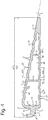
- FIG. 1 A cross section of an embodiment of a plank is shown in Figure 1 .
- the plank comprises a width direction (x) and a height direction (z).
- the length, width, and height direction are mutually orthogonal.
- the plank comprises a top side and a bottom side spaced in the height direction (z).
- the plank further comprises a top plate (1) near the top side and a bottom plate (2) near the bottom side.
- the top and bottom plates (1, 2) extend in the width direction (x) and are mutually separated by a plurality of spacing plates (3) in essence parallel to the height direction (z).
- the plank further comprises a male connection element (4, 5, 8, 9, 18) and a female connection element (11, 12, 13, 16, 19) separated in the width direction (x) by the top and bottom plates (1, 2) and connected to the top and bottom plates (1, 2).
- the male and female connection elements are hereby connected to opposite edges of the top and bottom plates (1 , 2), whereby the opposite edges are spaced in the width direction (x).
- the male connection element comprises a hook connection wall (8, 9) extending from the bottom plate (2) to the top plate (1) and a hook comprising a first hook portion (5) extending outwardly at least substantially in the width direction (x) from the hook connection wall (8, 9) to a corner hook portion (18) and a second hook portion (4) extending at least substantially in the height direction (z) from the corner hook portion (18) and towards the top side.
- the female connection element comprises a recess (29) formed by a lower recess wall (12) extending outwardly at least substantially in the width direction (x) from the bottom plate (2) to a lower recess wall end, a hind recess wall (13) extending from the bottom plate (2) to the top plate (1), and an upper recess wall comprising a first recess portion (16) extending outwardly at least substantially in the width direction (x) from the top plate (1) to a corner recess portion (19) and a second recess portion (11) extending at least substantially in the height direction (z) from the corner recess portion (19) and towards the lower recess wall (12).
- the recess (29) of the female connection element and the hook (4, 5, 18) of the male connection element are configured for loosely interlocking adjacent planks, allowing a modular floor built up of interlocked adjacent planks to conform to the contours of the supporting terrain, whether concaved or convexed.
- the modular floor may comprise a plank comprising two female connection elements spaced in the width direction of the plank and/or a plank comprising two male connection elements spaced in the width direction of the plank.
- the modular floor may consist solely of planks comprising two female or two male connection elements. In the latter case, male-type planks have to be alternated with female-type planks. This however requires a proper alternating stacking of the planks to properly lay out the modular floor.
- the lower recess wall (12) comprises an outer surface (14, 15) comprising a slanted portion (15) extending from a deflection line (17) towards said lower recess wall end and at least partially in the height direction (z) towards said top side.
- the slanted outer surface portion (15) comprises a slant size in the width direction equal to at least 50% of the female connection element size in the width direction, for enabling engagement of the recess (29) over the hook of the male connection element of another plank positioned on a subsurface.
- the slant size in the width direction is equal to at least 50% of the female connection element size in the width direction, such as 50%, 51%, 52%, 53%, 54%, 55%, 56%, 57%, 58%, 59%, 60%, 61%, 62%, 63%, 64%, 65%, 67.5%, 70%, 72.5%, 75%, 77.5%, 80%, 85%, 90%, 95%, or any percentage above or in between, of the female connection element size in the width direction.
- the slant size in the width direction is equal to at least 62.5% of said female connection element size in the width direction.
- FIGS. 5a to 5g show a schematic representation of a cross section of the engagement of the recess of the female connection element of a first plank (51) over the hook of the male connection element of a second plank (50), whereby the second plank (50) is positioned on a subsurface (52).
- Figures 6a to 6e show a schematic representation of a cross section of the engagement of the hook of the male connection element of a second plank (50) in the recess of the female connection element of a first plank (51), whereby the first plank (51) is positioned on a subsurface (52).
- Figure 5g illustrates that the first plank (51) and the second plank (50) are loosely interlocked, allowing a modular floor built up of interlocked adjacent planks to conform to the contours of the supporting terrain, whether concaved or convexed.
- placement of the recess (29) of the first plank (51) over the hook of the second plank (50) involves placement of the second recess portion (11) of the first plank (51) behind the second hook portion (4) of the second plank (50), thereby creating a loose hinge-type engagement between the second recess portion (11) of the first plank (51) and the second hook portion (4) of the second plank (50), around which the first plank (51) can be rotatively interlocked with the second plank (50), as shown in Figure sequence 5a to 5g, whereby the lower recess wall (12) of the first plank (51) is placed underneath the first hook portion (5) of the second plank (50) while maintaining said loose hinge-type engagement.
- the applicant has found that when the slanted outer surface portion (15) does not extend sufficiently far over the width of the lower recess wall (12), the lower recess wall (12) of the first plank (51) substantially scrapes against and/or protrudes in the subsurface (52) on which the second plank (50) rests upon rotatively engaging the recess (29) of the first plank (51) over the hook of the second plank (50).
- a slant size equal to at least 50% of the female connection element size in the width direction is sufficient to prevent said scraping against and/or protruding in the subsurface.
- said slanted outer surface portion (15) of said lower recess wall (12) comprises an angle ( ⁇ 1 ) with respect to the width direction (x) of at least 5 degrees, preferably at least 7 degrees, such as 7 degrees, 8 degrees, 9 degrees, 10 degrees, 11 degrees, or any value above or in between.
- an increasing angle between the slanted outer surface portion (15) and the width direction (x) also helps in preventing said scraping against and/or protruding in the subsurface of said lower recess wall (12).
- said angle cannot become too large, as the lower recess wall should maintain sufficient strength near its lower recess wall end. The maximum angle depends on material characteristics, the thickness of the lower recess wall near the deflection line (17), and the desired strength near the lower recess wall end.
- the upper recess wall of the female connection element (comprising the first recess portion (16), the corner recess portion (19), and the second recess portion (11)) extends outwardly in the width direction at least as far as the lower recess wall end of the female connection element.
- the upper recess wall and the lower recess wall extend outwardly in the width direction in essence equally far, thereby comprising a common tangent plane parallel to the height direction.
- the male connection wall comprises an outer surface in essence parallel to the height direction (z), and the male connection element further comprises an upper filleted connection corner (6) and a lower filleted connection corner (7) at the attachment of the first hook portion (5) to the outer surface of the hook connection wall, whereby the hook connection wall comprises for each of said upper and lower filleted connection corners (6, 7) an adjacently faced inwardly extending thickening (8, 9).
- the thickenings hereby merge in a confluence portion (10) of the hook connection wall comprising a thickness less than each of the maximum thicknesses in the width direction of said thickenings of the hook connection wall.
- the male and female connection elements are often subject to substantial stresses.
- the hook protrudes in the width direction away from the hook connection wall.
- the upper and lower recess walls protrude in the width direction away from the hind recess wall.
- These elements therefore often bump against other objects during transportation, for example, when a plank falls and hits the ground.
- they when interlocked, they also experience substantial forces in use, for example, when a vehicle drives over a modular floor of interlocked planks.
- These elements should therefore comprise sufficient strength so as to not plie themselves, for example at the corner hook portion or the corner recess portion, nor at the connection with the remainder of the plank, for example, where the first hook portion is attached to the hook connection wall.
- These elements are therefore manufactured at least partially thicker than the plank plates.
- the top plate (1) and the bottom plate (2) comprise a plurality of ribs extending in the length direction and interspersed with channels (20, 21).
- a schematic representation of a cross section of a plank comprising top and bottom plates comprising ribs and channels is provided in Figure 2 .
- the channels are advantageous for several reasons. They allow, for example, for partial drainage of rain water and other fluids, which would otherwise remain on the top plate and cause the top plate to be slippery.
- the channels provide grip, both for persons and vehicles moving on the top plate and for the plank with respect to the subsurface. Protrusions of the subsurface, soles of shoes, and wheels of vehicles may at least partially enter a channel, thereby providing a hook-type grip in the channel and preventing unwanted movement perpendicular to the length direction.
- each rib comprises an outer rib surface and each of the top and bottom plates comprises a channel bottom wall and two channel side walls.
- the channel bottom wall comprises a channel bottom surface (20) in essence parallel with the outer rib surfaces of the two adjacent ribs.
- Each of said two channel side walls comprises a channel side surface (21) extending from the channel bottom surface to the outer rib surface of one of said adjacent ribs.
- the channel bottom surface (20), the two side surfaces (21), and an open top face in essence coplanar with the outer rib surfaces of said two adjacent ribs delimit a channel.
- each of the top and bottom plates comprises a plurality of channel bottom walls and corresponding pairs of channel side walls, defining a plurality of channels.
- the two channel side surfaces (21) of a channel thereby comprise an angle of at least 120 degrees with the channel bottom surface (20), such as an angle of 120 degrees, 125 degrees, 130 degrees, 135 degrees, 140 degrees, 145 degrees, 150 degrees, or any value in between.
- each of said two channel side surfaces (21) comprises an angle of in essence 135 degrees with the channel bottom surface (20).
- said two channel side surfaces are in essence mutually perpendicular. This is advantageous as skew channel side walls (21) with respect to the channel bottom surface (20), as described above, limit the amount of dirt which can be accumulated in the corners in between channel side walls and the channel bottom wall. Furthermore, it also allows for accumulated dirt to be more easily removed from the channels.
- a washing process for removing accumulated dirt may involve the collection of rain water in a basin comprising a driving ramp, driving one or more plates into the basin, washing the plates, and removing the one or more plates from the basin.
- An outer rib surface comprises a rib width in the width direction.
- An open top face of a channel comprises a channel top width in the width direction.
- the channel top width is equal to at most 100% of said rib width, preferably at most 80% of said rib width, most preferably at most 60% of said rib width.
- each of the top and bottom plates comprises a plurality of channel bottom walls, whereby each spacing plate (3) of said plurality of spacing plates is connected (23) to a channel bottom wall of the top plate and a channel bottom wall of the bottom plate. Because a bottom wall is connected via skew channel side walls to the ribs and therefore the remainder of the top or bottom plate, shear and compression forces (in the width and/or height direction of the plank) are mediated to said remainder under two consecutive skew angles, thereby providing a more gradual transmission of said forces causing less stress on the interconnections between a spacing plate and the top and/or bottom plate.
- the modular floor also comprises at least one male ramp, in addition to said planks.
- a schematic representation of a male ramp is provided in Figure 4 .
- a male ramp also comprises a length direction, a width direction, and a height direction which are mutually orthogonal, and an in essence uniform cross section perpendicular to the length direction, as it is preferably manufactured by extrusion, and preferably in the same material as said planks.
- the male ramp further comprises a bottom plate (31) extending in the width direction, a ramp plate (30) comprising a nonzero angle ( ⁇ 2 ) with the bottom plate (31), and a male connection element (4, 5, 8, 9, 18) connected to said bottom and ramp plates and configured for interlocking said male ramp with a plank of the modular floor via the female connection element of said plank.
- a male connection element of a plank such as, for example, the filleted connection corners (6, 7) and the corresponding thickenings (8, 9) which merge in a narrower confluence portion (10) of the hook connection wall, can also pertain to said male ramp.
- specific features of preferred embodiments of the top and bottom plates of a plank such as, for example, the ribs interspersed with channels (20, 21) can also pertain to said male ramp.
- the modular floor also comprises at least one female ramp, in addition to said planks.
- a schematic representation of a female ramp is provided in Figure 3 .
- a female ramp also comprises a length direction, a width direction, and a height direction which are mutually orthogonal, and an in essence uniform cross section perpendicular to the length direction, as it is preferably manufactured by extrusion, and preferably in the same material as said planks.
- the female ramp further comprises a bottom plate (31) extending in the width direction, a ramp plate (30) comprising a nonzero angle ( ⁇ 2 ) with the bottom plate (31), and a female connection element (11, 12, 16, 19) connected to said bottom and ramp plates and configured for interlocking said female ramp with a plank of the modular floor via the male connection element of said plank.
- a female connection element of a plank such as, for example, the features related to the slanted outer surface portion (15) of the lower recess wall (12) can also pertain to said female ramp.
- specific features of preferred embodiments of the top and bottom plates of a plank such as, for example, the ribs interspersed with channels (20, 21) can also pertain to said female ramp.
- the male and female ramps are advantageous as they facilitate access to a modular floor of interlocked planks, for example, for driving on and/or off the modular floor with a vehicle.
- the method comprises the steps of:
- the method according to this preferred embodiment is advantageous as it allows to interlock a plank to an already positioned plank on a subsurface, with either one of the male and female connection element of said plank.
- a modular floor can be extended at both sides simultaneously, allowing for expeditious and flexible lay-out of the modular floor.
- said at least three planks comprise a fourth plank in essence identical to each of said at least three planks, and the method comprises at least one of the following steps:
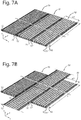
- the modular floor can hence be laid out in a straight configuration, as illustrated in Figure 7a , where a hook of a male connection element in essence completely interlocks in the recess of a female connection element, or alternatively in a staggered configuration, as illustrated in Figure 7b , where a connection element of a plank can partially interlock with the dual connection element of each of two other planks.
- the staggered configuration is advantageous for modular floors extending substantially in essence in the length direction (y) of the interlocked planks as to provide more interlocking stability as well as to prevent substantial height changes in between neighboring planks in the length direction (y).
- the modular floor can comprise a plurality of planks comprising a first length in the length direction and a plurality of planks comprising a second length in the length direction, whereby the second length is equal to in essence half of the first length.
- the example pertains to a modular floor comprising:
- the plurality of planks, the at least one female ramp, and the at least one male ramp are single-piece components, manufactured by extruding aluminum alloy 6005A which is heat-treated to the T-6 condition (aluminum alloy EN AW-6005A T6).
- Figures 5a to 5g show a cross section of the engagement of the recess of the female connection element of a first plank (51) of the modular system of this example over the hook of the male connection element of a second plank (50) of the modular system of this example, whereby the second plank (50) is positioned on a subsurface (52).
- Figures 6a to 6e show a cross section of the engagement of the hook of the male connection element of a second plank (50) of the modular system of this example in the recess of the female connection element of a first plank (51) of the modular system of this example, whereby the first plank (51) is positioned on a subsurface.
- planks of the modular floor of this example can be interlocked in regular configuration ( Figure 7a ) or in staggered configuration ( Figure 7b ).
- Figures 8 and 9 show a detailed cross section of the male connection element and the female connection element, respectively, of a plank of the modular system of this example.
- a plank comprises a length (l) of about 3000 mm in the length or extrusion direction (y), a total width (w3) of about 621.8 mm in the width direction (x), and a total height (h1) of about 45 mm in the height direction (z).
- the total height (h1) can also be smaller or larger.
- the plank may comprise a total height (h1) of 20 mm, 25 mm, 30 mm, 35 mm, 40 mm, 45 mm, 50 mm, 55 mm, 60 mm, 65 mm, 70 mm, 75 mm, 80 mm, 85 mm, 90 mm, 95 mm, 100 mm, or any value above or in between.
- the plank is typically better able to withstand bending stresses as the total height (h1) increases.
- the total height (h1) is 45 mm.
- the total width (w3) consists of the plank connection width (w1) of about 600 mm in between and including the hook connection wall and the female connection element and the protrusion length (w9) of about 21.8 mm of the hook in the width direction.
- the distance (w2) in between two neighboring and in essence parallel spacing plates is about 69 mm.
- the thickness of the top plate ribs (d2), top plate channel bottom walls (d1), and top plate channel side walls (d3) is about 4 mm.
- the thickness of the bottom plate ribs (d5), bottom plate channel bottom walls (d4), and bottom plate channel side walls (d6) is about 3 mm.
- the thickness of the spacing plates is about 3 mm.
- the top plate therefore comprises a thickness which is larger than the thicknesses of the spacing plates and the bottom plate.
- the channels comprise a depth (h2, h3) in the height direction (z) of about 2 mm.
- the channel top width (w4) is about 9 mm and the rib width (w5) is about 15 mm. Therefore, the channel top width is equal to about 60% of the channel top width.
- the channel side walls comprise an angle with the corresponding channel bottom wall of about 135 degrees. Therefore, the channel bottom surface comprises a channel bottom width (w13) of about 5 mm.
- the inwardly directed face of the channel bottom wall at the top plate comprises a width (w6) of about 8.3 mm, which is larger than the width (w7) of about 7.5 mm of the inwardly directed face of the channel bottom wall at the bottom plate.
- the female connection element comprises a wall thickness at the lower recess wall (h9), the hind recess wall (w18) and the upper recess wall (w6, h7) of at least about 7 mm.
- the thickenings of the hook connection wall comprise a width (w11) of about 8 mm, which is significantly more than the width (w12) of about 5 mm of the confluence portion of the hook connection wall.
- the first hook portion comprises a width in the height direction of about 12 mm.
- the female connection element comprises a female connection element size in the width direction (w17 + w18) of about 30.3 mm.
- the slanted size in the width direction (w20) is about 18.94 mm. Therefore, the slanted size is equal to about 62.51 % of the female connection element size.
- the slanted outer surface portion comprises an angle ( ⁇ 1 ) with respect to the width direction of 9 degrees.
- the plank comprises eight box-like sections formed by the seven spacing plates.
- the female and male ramps comprise a ramp connection width (w22) of about 220 mm.
- the total width of a male ramp (w23) is about 241.8 mm due to the protrusion length (w9) of the hook of about 21.8 mm.
- the ramp plate (30) and the bottom plate (31) comprise an angle in between ( ⁇ 2) of about 10.78 degrees.
- the ramp plate (30) comprises a thickness (d1, d2, d3) of about 4 mm, while the bottom plate (31) and the spacing plates comprise a thickness (d4, d5, d6, d7) of about 3 mm.
Landscapes
- Engineering & Computer Science (AREA)
- Architecture (AREA)
- Civil Engineering (AREA)
- Structural Engineering (AREA)
- Floor Finish (AREA)
- Body Structure For Vehicles (AREA)
- Bridges Or Land Bridges (AREA)
- Road Paving Structures (AREA)
Priority Applications (9)
| Application Number | Priority Date | Filing Date | Title |
|---|---|---|---|
| EP17170002.4A EP3401441B1 (fr) | 2017-05-08 | 2017-05-08 | Plancher modulaire destiné à fournir un support à des véhicules et des foules sur une subsurface souple ou irrégulière et planche, procédé d'installation et procédé de production associé |
| ES17170002T ES2816052T3 (es) | 2017-05-08 | 2017-05-08 | Suelo modular para proporcionar soporte a vehículos y multitudes sobre una subsuperficie blanda o desigual, y tabla, método de instalación y método de producción para el mismo |
| PT171700024T PT3401441T (pt) | 2017-05-08 | 2017-05-08 | Pavimento modular concebido para suportar veículos e multidões numa subsuperfície irregular ou mole, e prancha, método de instalação e método de produção associados |
| BE2017/5808A BE1025716B1 (nl) | 2017-05-08 | 2017-11-08 | Modulaire vloer voor het bieden van ondersteuning aan voertuigen en mensen op een oneffen of zachte ondergrond, en plank, installatiewerkwijze, en productiewerkwijze daarvoor |
| CA3061561A CA3061561C (fr) | 2017-05-08 | 2018-05-08 | Plancher modulaire pour fournir un support a des vehicules et des personnes sur une sous-surface irreguliere ou molle, et planche, procede d'installation et procede de production associe |
| PCT/EP2018/061909 WO2018206597A2 (fr) | 2017-05-08 | 2018-05-08 | Plancher modulaire pour fournir un support à des véhicules et des personnes sur une sous-surface irrégulière ou molle, et planche, procédé d'installation et procédé de production associé |
| US16/611,560 US11198976B2 (en) | 2017-05-08 | 2018-05-08 | Modular floor for providing support to vehicles and crowds on an uneven or soft subsurface, and plank, installation method, and production method therefor |
| AU2018264962A AU2018264962B2 (en) | 2017-05-08 | 2018-05-08 | Modular floor for providing support to vehicles and crowds on an uneven or soft subsurface, and plank, installation method, and production method therefor |
| IL270430A IL270430B2 (en) | 2017-05-08 | 2018-05-08 | Modular floor for providing support to vehicles and crowds on an uneven or soft subsurface, and plank, installation method, and production method therefor |
Applications Claiming Priority (1)
| Application Number | Priority Date | Filing Date | Title |
|---|---|---|---|
| EP17170002.4A EP3401441B1 (fr) | 2017-05-08 | 2017-05-08 | Plancher modulaire destiné à fournir un support à des véhicules et des foules sur une subsurface souple ou irrégulière et planche, procédé d'installation et procédé de production associé |
Publications (2)
| Publication Number | Publication Date |
|---|---|
| EP3401441A1 true EP3401441A1 (fr) | 2018-11-14 |
| EP3401441B1 EP3401441B1 (fr) | 2020-07-01 |
Family
ID=58692420
Family Applications (1)
| Application Number | Title | Priority Date | Filing Date |
|---|---|---|---|
| EP17170002.4A Active EP3401441B1 (fr) | 2017-05-08 | 2017-05-08 | Plancher modulaire destiné à fournir un support à des véhicules et des foules sur une subsurface souple ou irrégulière et planche, procédé d'installation et procédé de production associé |
Country Status (9)
| Country | Link |
|---|---|
| US (1) | US11198976B2 (fr) |
| EP (1) | EP3401441B1 (fr) |
| AU (1) | AU2018264962B2 (fr) |
| BE (1) | BE1025716B1 (fr) |
| CA (1) | CA3061561C (fr) |
| ES (1) | ES2816052T3 (fr) |
| IL (1) | IL270430B2 (fr) |
| PT (1) | PT3401441T (fr) |
| WO (1) | WO2018206597A2 (fr) |
Cited By (2)
| Publication number | Priority date | Publication date | Assignee | Title |
|---|---|---|---|---|
| CN111874792A (zh) * | 2020-07-31 | 2020-11-03 | 中国十九冶集团有限公司 | 吊装路基箱装置 |
| CN111959457A (zh) * | 2020-08-26 | 2020-11-20 | 中国十九冶集团有限公司 | 重型装载车辆防陷支撑装置 |
Families Citing this family (3)
| Publication number | Priority date | Publication date | Assignee | Title |
|---|---|---|---|---|
| BE1027024B1 (nl) * | 2019-02-04 | 2020-09-02 | Flooring Ind Ltd Sarl | Vloerpaneel en werkwijze voor het vervaardigen ervan |
| DE102021117145A1 (de) | 2021-07-02 | 2023-01-05 | Cteam Consulting & Anlagenbau Gmbh | Modularer Bodenbelag |
| CN119553564B (zh) * | 2024-12-30 | 2025-09-23 | 武汉科技大学 | 一种临时路面装置以及临时道路 |
Citations (4)
| Publication number | Priority date | Publication date | Assignee | Title |
|---|---|---|---|---|
| US3301147A (en) | 1963-07-22 | 1967-01-31 | Harvey Aluminum Inc | Vehicle-supporting matting and plank therefor |
| US3557670A (en) * | 1968-05-27 | 1971-01-26 | Paul Thomas Sutton | Patch assembly for rapid repair of bomb-damaged runways and pavements |
| US3614915A (en) * | 1969-01-21 | 1971-10-26 | Kaiser Aluminium Chem Corp | Panel assembly and method |
| EP1950349A2 (fr) * | 2007-01-25 | 2008-07-30 | EPS GmbH | Revêtement de sol |
Family Cites Families (17)
| Publication number | Priority date | Publication date | Assignee | Title |
|---|---|---|---|---|
| US3385182A (en) * | 1965-09-27 | 1968-05-28 | Harvey Aluminum Inc | Interlocking device for load bearing surfaces such as aircraft landing mats |
| US3385183A (en) * | 1965-10-22 | 1968-05-28 | Harvey Aluminum Inc | Keylock-typical section |
| US3348459A (en) * | 1967-01-03 | 1967-10-24 | Harvey Aluminum Inc | Interlocking matting and coupling bar therefor |
| US3377931A (en) * | 1967-05-26 | 1968-04-16 | Ralph W. Hilton | Plank for modular load bearing surfaces such as aircraft landing mats |
| US3450010A (en) * | 1968-03-08 | 1969-06-17 | Harvey Aluminum Inc | Landing mat |
| US3572224A (en) * | 1968-10-14 | 1971-03-23 | Kaiser Aluminium Chem Corp | Load supporting plank system |
| USRE27147E (en) * | 1969-11-04 | 1971-06-22 | Landing mat | |
| US3784312A (en) * | 1972-06-12 | 1974-01-08 | Us Navy | Flotation beam for matting construction |
| IL129834A (en) * | 1999-05-06 | 2001-09-13 | Ackerstein Ind Ltd | Ground surface cover system with flexible interlocking joint for erosion control |
| DE60037661T2 (de) * | 1999-07-02 | 2009-01-08 | Excellent Systems A/S | Vorrichtung zur einfachen Überwindung von Höhendifferenzen, insbesondere bei Türschwellen, durch Rollstuhlfahrer |
| US6526614B2 (en) * | 2001-04-09 | 2003-03-04 | The United States Of America As Represented By The Secretary Of The Navy | Portable and lightweight ramp structure |
| US7370452B2 (en) * | 2002-09-16 | 2008-05-13 | Rogers Melissa B | Mat assembly for heavy equipment transit and support |
| US7090430B1 (en) * | 2003-06-23 | 2006-08-15 | Ground Floor Systems, Llc | Roll-up surface, system and method |
| US7364383B2 (en) * | 2004-06-23 | 2008-04-29 | Ground Floor Systems, Llc | Roll-up surface, system and method |
| US8336146B1 (en) * | 2011-06-13 | 2012-12-25 | Berbash Khaled M | Forced air heated mat |
| US10907348B2 (en) * | 2013-11-07 | 2021-02-02 | Csr Building Products Limited | Building component |
| CN111576724B (zh) * | 2013-11-07 | 2022-06-07 | Csr建筑产品有限公司 | 建筑部件 |
-
2017
- 2017-05-08 ES ES17170002T patent/ES2816052T3/es active Active
- 2017-05-08 EP EP17170002.4A patent/EP3401441B1/fr active Active
- 2017-05-08 PT PT171700024T patent/PT3401441T/pt unknown
- 2017-11-08 BE BE2017/5808A patent/BE1025716B1/nl not_active IP Right Cessation
-
2018
- 2018-05-08 CA CA3061561A patent/CA3061561C/fr active Active
- 2018-05-08 US US16/611,560 patent/US11198976B2/en active Active
- 2018-05-08 WO PCT/EP2018/061909 patent/WO2018206597A2/fr not_active Ceased
- 2018-05-08 AU AU2018264962A patent/AU2018264962B2/en active Active
- 2018-05-08 IL IL270430A patent/IL270430B2/en unknown
Patent Citations (4)
| Publication number | Priority date | Publication date | Assignee | Title |
|---|---|---|---|---|
| US3301147A (en) | 1963-07-22 | 1967-01-31 | Harvey Aluminum Inc | Vehicle-supporting matting and plank therefor |
| US3557670A (en) * | 1968-05-27 | 1971-01-26 | Paul Thomas Sutton | Patch assembly for rapid repair of bomb-damaged runways and pavements |
| US3614915A (en) * | 1969-01-21 | 1971-10-26 | Kaiser Aluminium Chem Corp | Panel assembly and method |
| EP1950349A2 (fr) * | 2007-01-25 | 2008-07-30 | EPS GmbH | Revêtement de sol |
Cited By (2)
| Publication number | Priority date | Publication date | Assignee | Title |
|---|---|---|---|---|
| CN111874792A (zh) * | 2020-07-31 | 2020-11-03 | 中国十九冶集团有限公司 | 吊装路基箱装置 |
| CN111959457A (zh) * | 2020-08-26 | 2020-11-20 | 中国十九冶集团有限公司 | 重型装载车辆防陷支撑装置 |
Also Published As
| Publication number | Publication date |
|---|---|
| AU2018264962A1 (en) | 2019-11-28 |
| PT3401441T (pt) | 2020-09-04 |
| ES2816052T3 (es) | 2021-03-31 |
| IL270430B2 (en) | 2024-08-01 |
| EP3401441B1 (fr) | 2020-07-01 |
| IL270430B1 (en) | 2024-04-01 |
| US11198976B2 (en) | 2021-12-14 |
| AU2018264962B2 (en) | 2023-08-03 |
| WO2018206597A3 (fr) | 2018-12-20 |
| IL270430A (fr) | 2020-01-30 |
| BE1025716A1 (nl) | 2019-06-12 |
| CA3061561C (fr) | 2023-11-28 |
| CA3061561A1 (fr) | 2018-11-15 |
| WO2018206597A2 (fr) | 2018-11-15 |
| BE1025716B1 (nl) | 2019-06-20 |
| US20210148060A1 (en) | 2021-05-20 |
Similar Documents
| Publication | Publication Date | Title |
|---|---|---|
| EP3401441B1 (fr) | Plancher modulaire destiné à fournir un support à des véhicules et des foules sur une subsurface souple ou irrégulière et planche, procédé d'installation et procédé de production associé | |
| EP3365494B1 (fr) | Tapis de sol modulaire | |
| US3836075A (en) | Cleated emergency track | |
| US6740380B2 (en) | Floor mat system | |
| US4087948A (en) | Flooring elements | |
| US20190284818A1 (en) | Segmented panel mat | |
| US20050117969A1 (en) | Anti-slip step for a motor vehicle and a method of forming the same | |
| CA2498575A1 (fr) | Panneaux entrelaces pour surfaces de support | |
| US9163365B2 (en) | Anti-icing system | |
| US20250179805A1 (en) | Modular ramp | |
| EP0887466B1 (fr) | Cylindre compresseur a pneumatiques | |
| GB2527676A (en) | Floor covering panel system | |
| CA2890811C (fr) | Dispositif a traction | |
| KR200364765Y1 (ko) | 철도 차량용 논슬립 매트 | |
| US11160407B2 (en) | Garage floor protection mat for snowmobiles and the like | |
| DE102013103339A1 (de) | Boden für ein Nutzfahrzeug und mit einem solchen Boden ausgestattetes Nutzfahrzeug | |
| JPH0620641Y2 (ja) | 悪路脱出用具 | |
| CN121915858A (zh) | 一种升降横移立库的带有踏板构造的底层横移载车板 | |
| JP4020671B2 (ja) | タイヤローラ | |
| US20060087094A1 (en) | Anti-slip step for a motor vehicle and a method of forming the same | |
| CA2416045C (fr) | Tapis de plancher en sections | |
| JPH0513601Y2 (fr) | ||
| DE9102141U1 (de) | Bodenbelag | |
| JP2004250878A (ja) | 道路マット | |
| GB1573303A (en) | Flooring elements |
Legal Events
| Date | Code | Title | Description |
|---|---|---|---|
| PUAI | Public reference made under article 153(3) epc to a published international application that has entered the european phase |
Free format text: ORIGINAL CODE: 0009012 |
|
| STAA | Information on the status of an ep patent application or granted ep patent |
Free format text: STATUS: THE APPLICATION HAS BEEN PUBLISHED |
|
| AK | Designated contracting states |
Kind code of ref document: A1 Designated state(s): AL AT BE BG CH CY CZ DE DK EE ES FI FR GB GR HR HU IE IS IT LI LT LU LV MC MK MT NL NO PL PT RO RS SE SI SK SM TR |
|
| AX | Request for extension of the european patent |
Extension state: BA ME |
|
| STAA | Information on the status of an ep patent application or granted ep patent |
Free format text: STATUS: REQUEST FOR EXAMINATION WAS MADE |
|
| 17P | Request for examination filed |
Effective date: 20190509 |
|
| RBV | Designated contracting states (corrected) |
Designated state(s): AL AT BE BG CH CY CZ DE DK EE ES FI FR GB GR HR HU IE IS IT LI LT LU LV MC MK MT NL NO PL PT RO RS SE SI SK SM TR |
|
| GRAP | Despatch of communication of intention to grant a patent |
Free format text: ORIGINAL CODE: EPIDOSNIGR1 |
|
| STAA | Information on the status of an ep patent application or granted ep patent |
Free format text: STATUS: GRANT OF PATENT IS INTENDED |
|
| INTG | Intention to grant announced |
Effective date: 20191203 |
|
| GRAS | Grant fee paid |
Free format text: ORIGINAL CODE: EPIDOSNIGR3 |
|
| GRAA | (expected) grant |
Free format text: ORIGINAL CODE: 0009210 |
|
| STAA | Information on the status of an ep patent application or granted ep patent |
Free format text: STATUS: THE PATENT HAS BEEN GRANTED |
|
| AK | Designated contracting states |
Kind code of ref document: B1 Designated state(s): AL AT BE BG CH CY CZ DE DK EE ES FI FR GB GR HR HU IE IS IT LI LT LU LV MC MK MT NL NO PL PT RO RS SE SI SK SM TR |
|
| REG | Reference to a national code |
Ref country code: CH Ref legal event code: EP Ref country code: AT Ref legal event code: REF Ref document number: 1286288 Country of ref document: AT Kind code of ref document: T Effective date: 20200715 |
|
| REG | Reference to a national code |
Ref country code: IE Ref legal event code: FG4D |
|
| REG | Reference to a national code |
Ref country code: DE Ref legal event code: R096 Ref document number: 602017018894 Country of ref document: DE |
|
| REG | Reference to a national code |
Ref country code: PT Ref legal event code: SC4A Ref document number: 3401441 Country of ref document: PT Date of ref document: 20200904 Kind code of ref document: T Free format text: AVAILABILITY OF NATIONAL TRANSLATION Effective date: 20200831 |
|
| REG | Reference to a national code |
Ref country code: NL Ref legal event code: FP |
|
| REG | Reference to a national code |
Ref country code: LT Ref legal event code: MG4D |
|
| PG25 | Lapsed in a contracting state [announced via postgrant information from national office to epo] |
Ref country code: BG Free format text: LAPSE BECAUSE OF FAILURE TO SUBMIT A TRANSLATION OF THE DESCRIPTION OR TO PAY THE FEE WITHIN THE PRESCRIBED TIME-LIMIT Effective date: 20201001 |
|
| REG | Reference to a national code |
Ref country code: AT Ref legal event code: MK05 Ref document number: 1286288 Country of ref document: AT Kind code of ref document: T Effective date: 20200701 |
|
| PG25 | Lapsed in a contracting state [announced via postgrant information from national office to epo] |
Ref country code: FI Free format text: LAPSE BECAUSE OF FAILURE TO SUBMIT A TRANSLATION OF THE DESCRIPTION OR TO PAY THE FEE WITHIN THE PRESCRIBED TIME-LIMIT Effective date: 20200701 Ref country code: CZ Free format text: LAPSE BECAUSE OF FAILURE TO SUBMIT A TRANSLATION OF THE DESCRIPTION OR TO PAY THE FEE WITHIN THE PRESCRIBED TIME-LIMIT Effective date: 20200701 Ref country code: AT Free format text: LAPSE BECAUSE OF FAILURE TO SUBMIT A TRANSLATION OF THE DESCRIPTION OR TO PAY THE FEE WITHIN THE PRESCRIBED TIME-LIMIT Effective date: 20200701 Ref country code: NO Free format text: LAPSE BECAUSE OF FAILURE TO SUBMIT A TRANSLATION OF THE DESCRIPTION OR TO PAY THE FEE WITHIN THE PRESCRIBED TIME-LIMIT Effective date: 20201001 Ref country code: GR Free format text: LAPSE BECAUSE OF FAILURE TO SUBMIT A TRANSLATION OF THE DESCRIPTION OR TO PAY THE FEE WITHIN THE PRESCRIBED TIME-LIMIT Effective date: 20201002 Ref country code: SE Free format text: LAPSE BECAUSE OF FAILURE TO SUBMIT A TRANSLATION OF THE DESCRIPTION OR TO PAY THE FEE WITHIN THE PRESCRIBED TIME-LIMIT Effective date: 20200701 Ref country code: HR Free format text: LAPSE BECAUSE OF FAILURE TO SUBMIT A TRANSLATION OF THE DESCRIPTION OR TO PAY THE FEE WITHIN THE PRESCRIBED TIME-LIMIT Effective date: 20200701 Ref country code: LT Free format text: LAPSE BECAUSE OF FAILURE TO SUBMIT A TRANSLATION OF THE DESCRIPTION OR TO PAY THE FEE WITHIN THE PRESCRIBED TIME-LIMIT Effective date: 20200701 |
|
| PG25 | Lapsed in a contracting state [announced via postgrant information from national office to epo] |
Ref country code: PL Free format text: LAPSE BECAUSE OF FAILURE TO SUBMIT A TRANSLATION OF THE DESCRIPTION OR TO PAY THE FEE WITHIN THE PRESCRIBED TIME-LIMIT Effective date: 20200701 Ref country code: RS Free format text: LAPSE BECAUSE OF FAILURE TO SUBMIT A TRANSLATION OF THE DESCRIPTION OR TO PAY THE FEE WITHIN THE PRESCRIBED TIME-LIMIT Effective date: 20200701 Ref country code: LV Free format text: LAPSE BECAUSE OF FAILURE TO SUBMIT A TRANSLATION OF THE DESCRIPTION OR TO PAY THE FEE WITHIN THE PRESCRIBED TIME-LIMIT Effective date: 20200701 Ref country code: IS Free format text: LAPSE BECAUSE OF FAILURE TO SUBMIT A TRANSLATION OF THE DESCRIPTION OR TO PAY THE FEE WITHIN THE PRESCRIBED TIME-LIMIT Effective date: 20201101 |
|
| REG | Reference to a national code |
Ref country code: ES Ref legal event code: FG2A Ref document number: 2816052 Country of ref document: ES Kind code of ref document: T3 Effective date: 20210331 |
|
| REG | Reference to a national code |
Ref country code: DE Ref legal event code: R097 Ref document number: 602017018894 Country of ref document: DE |
|
| PG25 | Lapsed in a contracting state [announced via postgrant information from national office to epo] |
Ref country code: RO Free format text: LAPSE BECAUSE OF FAILURE TO SUBMIT A TRANSLATION OF THE DESCRIPTION OR TO PAY THE FEE WITHIN THE PRESCRIBED TIME-LIMIT Effective date: 20200701 Ref country code: DK Free format text: LAPSE BECAUSE OF FAILURE TO SUBMIT A TRANSLATION OF THE DESCRIPTION OR TO PAY THE FEE WITHIN THE PRESCRIBED TIME-LIMIT Effective date: 20200701 Ref country code: EE Free format text: LAPSE BECAUSE OF FAILURE TO SUBMIT A TRANSLATION OF THE DESCRIPTION OR TO PAY THE FEE WITHIN THE PRESCRIBED TIME-LIMIT Effective date: 20200701 Ref country code: SM Free format text: LAPSE BECAUSE OF FAILURE TO SUBMIT A TRANSLATION OF THE DESCRIPTION OR TO PAY THE FEE WITHIN THE PRESCRIBED TIME-LIMIT Effective date: 20200701 |
|
| PLBE | No opposition filed within time limit |
Free format text: ORIGINAL CODE: 0009261 |
|
| STAA | Information on the status of an ep patent application or granted ep patent |
Free format text: STATUS: NO OPPOSITION FILED WITHIN TIME LIMIT |
|
| PG25 | Lapsed in a contracting state [announced via postgrant information from national office to epo] |
Ref country code: AL Free format text: LAPSE BECAUSE OF FAILURE TO SUBMIT A TRANSLATION OF THE DESCRIPTION OR TO PAY THE FEE WITHIN THE PRESCRIBED TIME-LIMIT Effective date: 20200701 |
|
| 26N | No opposition filed |
Effective date: 20210406 |
|
| PG25 | Lapsed in a contracting state [announced via postgrant information from national office to epo] |
Ref country code: SK Free format text: LAPSE BECAUSE OF FAILURE TO SUBMIT A TRANSLATION OF THE DESCRIPTION OR TO PAY THE FEE WITHIN THE PRESCRIBED TIME-LIMIT Effective date: 20200701 |
|
| PG25 | Lapsed in a contracting state [announced via postgrant information from national office to epo] |
Ref country code: SI Free format text: LAPSE BECAUSE OF FAILURE TO SUBMIT A TRANSLATION OF THE DESCRIPTION OR TO PAY THE FEE WITHIN THE PRESCRIBED TIME-LIMIT Effective date: 20200701 |
|
| PG25 | Lapsed in a contracting state [announced via postgrant information from national office to epo] |
Ref country code: CY Free format text: LAPSE BECAUSE OF FAILURE TO SUBMIT A TRANSLATION OF THE DESCRIPTION OR TO PAY THE FEE WITHIN THE PRESCRIBED TIME-LIMIT Effective date: 20200701 |
|
| PG25 | Lapsed in a contracting state [announced via postgrant information from national office to epo] |
Ref country code: HU Free format text: LAPSE BECAUSE OF FAILURE TO SUBMIT A TRANSLATION OF THE DESCRIPTION OR TO PAY THE FEE WITHIN THE PRESCRIBED TIME-LIMIT; INVALID AB INITIO Effective date: 20170508 |
|
| PG25 | Lapsed in a contracting state [announced via postgrant information from national office to epo] |
Ref country code: MK Free format text: LAPSE BECAUSE OF FAILURE TO SUBMIT A TRANSLATION OF THE DESCRIPTION OR TO PAY THE FEE WITHIN THE PRESCRIBED TIME-LIMIT Effective date: 20200701 |
|
| PG25 | Lapsed in a contracting state [announced via postgrant information from national office to epo] |
Ref country code: MT Free format text: LAPSE BECAUSE OF FAILURE TO SUBMIT A TRANSLATION OF THE DESCRIPTION OR TO PAY THE FEE WITHIN THE PRESCRIBED TIME-LIMIT Effective date: 20200701 |
|
| PGFP | Annual fee paid to national office [announced via postgrant information from national office to epo] |
Ref country code: NL Payment date: 20250521 Year of fee payment: 9 |
|
| PGFP | Annual fee paid to national office [announced via postgrant information from national office to epo] |
Ref country code: MC Payment date: 20250527 Year of fee payment: 9 |
|
| PGFP | Annual fee paid to national office [announced via postgrant information from national office to epo] |
Ref country code: DE Payment date: 20250521 Year of fee payment: 9 |
|
| PGFP | Annual fee paid to national office [announced via postgrant information from national office to epo] |
Ref country code: GB Payment date: 20250527 Year of fee payment: 9 |
|
| PGFP | Annual fee paid to national office [announced via postgrant information from national office to epo] |
Ref country code: LU Payment date: 20250521 Year of fee payment: 9 Ref country code: BE Payment date: 20250521 Year of fee payment: 9 Ref country code: IT Payment date: 20250527 Year of fee payment: 9 |
|
| PGFP | Annual fee paid to national office [announced via postgrant information from national office to epo] |
Ref country code: PT Payment date: 20250429 Year of fee payment: 9 |
|
| PGFP | Annual fee paid to national office [announced via postgrant information from national office to epo] |
Ref country code: FR Payment date: 20250528 Year of fee payment: 9 |
|
| PGFP | Annual fee paid to national office [announced via postgrant information from national office to epo] |
Ref country code: CH Payment date: 20250601 Year of fee payment: 9 |
|
| PGFP | Annual fee paid to national office [announced via postgrant information from national office to epo] |
Ref country code: IE Payment date: 20250521 Year of fee payment: 9 |
|
| PGFP | Annual fee paid to national office [announced via postgrant information from national office to epo] |
Ref country code: ES Payment date: 20250630 Year of fee payment: 9 |
|
| PG25 | Lapsed in a contracting state [announced via postgrant information from national office to epo] |
Ref country code: TR Free format text: LAPSE BECAUSE OF FAILURE TO SUBMIT A TRANSLATION OF THE DESCRIPTION OR TO PAY THE FEE WITHIN THE PRESCRIBED TIME-LIMIT Effective date: 20200701 |