EP3401453B1 - Siphon hydraulique - Google Patents
Siphon hydraulique Download PDFInfo
- Publication number
- EP3401453B1 EP3401453B1 EP18170303.4A EP18170303A EP3401453B1 EP 3401453 B1 EP3401453 B1 EP 3401453B1 EP 18170303 A EP18170303 A EP 18170303A EP 3401453 B1 EP3401453 B1 EP 3401453B1
- Authority
- EP
- European Patent Office
- Prior art keywords
- trap
- external
- wall
- flange
- internal
- Prior art date
- Legal status (The legal status is an assumption and is not a legal conclusion. Google has not performed a legal analysis and makes no representation as to the accuracy of the status listed.)
- Active
Links
Images




Classifications
-
- E—FIXED CONSTRUCTIONS
- E03—WATER SUPPLY; SEWERAGE
- E03F—SEWERS; CESSPOOLS
- E03F5/00—Sewerage structures
- E03F5/04—Gullies inlets, road sinks, floor drains with or without odour seals or sediment traps
- E03F5/0407—Floor drains for indoor use
- E03F5/0408—Floor drains for indoor use specially adapted for showers
-
- E—FIXED CONSTRUCTIONS
- E03—WATER SUPPLY; SEWERAGE
- E03F—SEWERS; CESSPOOLS
- E03F5/00—Sewerage structures
- E03F5/04—Gullies inlets, road sinks, floor drains with or without odour seals or sediment traps
- E03F5/0407—Floor drains for indoor use
-
- E—FIXED CONSTRUCTIONS
- E03—WATER SUPPLY; SEWERAGE
- E03F—SEWERS; CESSPOOLS
- E03F5/00—Sewerage structures
- E03F5/04—Gullies inlets, road sinks, floor drains with or without odour seals or sediment traps
- E03F5/06—Gully gratings
-
- E—FIXED CONSTRUCTIONS
- E03—WATER SUPPLY; SEWERAGE
- E03F—SEWERS; CESSPOOLS
- E03F5/00—Sewerage structures
- E03F5/04—Gullies inlets, road sinks, floor drains with or without odour seals or sediment traps
- E03F5/06—Gully gratings
- E03F2005/065—Gully gratings with elastic locking elements
Definitions
- the present invention relates to a trap according to the preamble of claim 1.
- Such traps to which the invention relates have the major advantage that they are located in the space delimited by the tank, such that they are easily accessible, contrary to traps provided externally to such tanks and which are imbedded in screed, are located under a floor, and the like.
- such tank will be installed in a floor, but according to the invention this is not necessarily the case.
- a grille intended to be mounted in the opening on the internal part in order to prevent oversized elements in the discharge water or the discharge fluid from flowing through to the internal part or to prevent insects and vermin coming from the sewer system.
- the known traps of the aforementioned type are designed in such a way that the grille is difficult to access or the grille can easily be installed wrongly.
- the purpose of the present invention is therefore to provide a solution for one or several of the aforementioned or possible other disadvantages.
- a purpose of the present invention is to provide an improved trap of the type that can be installed in a tank and whereby the risk of leakage is limited as much as possible.
- Another purpose of the invention is to make improvements to a trap of the aforementioned type which ensure that a grille can be fitted without any problem and faultlessly over a discharge opening.
- Another purpose of the invention is to improve the efficiency when using a trap of the described type and to limit the costs related with both the manufacture and the installation of such trap as much as possible.
- WO2016071318 discloses a trap, which comprises a first drainage channel situated between an inlet and an outlet, comprising, viewed in the flow direction, a first closing wall for the closing off of an uppermost part of the drainage channel and a second closing wall for the closing off of a lowermost part of the first drainage channel.
- the first and second closing walls viewed in a horizontal direction, overlap.
- the odor trap comprises an elongated main body.
- the inlet substantially extends over the length of a first planar surface of the main body, which first planar surface is determined by the first closing wall.
- the second closing wall is situated in the main body.
- the outlet is situated in a second planar surface, situated opposite the first planar surface.
- WO2014209107 discloses a siphon assembly comprising a transit tube part and a siphon unit.
- the siphon unit comprises a siphon container with a bottom and side walls; a passage in front wall; and around the passage a collar of rubber or silicone extending out of the front wall.
- the siphon unit further comprises a siphon cap with an upper side and side walls, and a passage in a front wall.
- the siphon container is arranged within the siphon cap, with the collar extending outwards through the passage of the siphon cap.
- the invention relates to a trap that is suitable for use in a water discharge tank, whereby the trap is intended to be installed in the tank and connected to an opening in a wall of the tank that leads to a drain pipe of the sewer or an end of such drain pipe that extends against the wall of the tank or through the wall of the tank into the tank, whereby the trap, moreover, is at least provided with the following elements:
- An advantage of a trap according to the invention is that the grille is very easily accessible.
- Another preferred characteristic of a trap according to the invention consists in connecting the external wall of the external part and the internal wall of the internal part of the trap in a fixed way.
- An advantage of such embodiment of a trap according to the invention is that the trap can be installed as one unit, whereby the internal part and practically the entire external part of the trap no longer have to be disassembled for maintenance, etc. later.
- the external wall and the internal wall come together on the level of a common wall part, whereby in this common wall part a transit opening is provided for connection to the aforementioned drain pipe of the tank.
- the internal wall of the internal part and the external wall of the external part are each provided with a transit opening intended for connection to the aforementioned drain pipe of the tank.
- Such embodiment of a trap according to the invention does not have the advantage that only one transit opening is applied to connect to a drain pipe.
- Another preferred aspect of a trap according to the invention consists in designing the trap in such a way with a view to an assembly whereby the opening in the wall of the tank, the opening in the external wall and the opening in the internal wall extend in line with each other.
- An advantage of such embodiment of a trap according to the invention is that all parts of the trap are well aligned to each other for an efficient installation of the trap and the connection thereof to a drain pipe.
- the trap is also provided with a separate connecting piece to connect the trap to the drain pipe on the aforementioned tank, whereby the connecting piece is essentially formed by a pipe section that is provided with a flange on one end.
- the connecting piece is preferably designed with a view to an assembly whereby the pipe section is centred over the transit opening in the common wall part of the external wall and the internal wall of the trap.
- the external wall of the external part of the trap and the connecting piece are preferably provided with complementary connecting parts in order to be able to attach the flange of the connecting piece in a detachable way to the external part of the trap and this in such a way that the flange is pressed against the external part of the trap.
- Such embodiment of a trap according to the invention ensures the correct connection and minimises the risk of leaks.
- Such embodiment of a trap according to the invention offers a very efficient solution to connect the trap to a drain pipe of a tank.
- the flange is provided with parts raised from the plane of the flange and this in the positions of the flange that are caught between the hooks on the external wall of the trap, when the flange has been installed in the correct location for the alignment of the pipe section of the connecting piece with the transit opening in the trap.
- Such embodiment of a trap according to the invention ensures an easy connection of the connecting piece with the remaining part of the trap, whereby by pressing the flange against the external wall of the trap a watertight connection is ensured.
- the invention also relates to a trap with all the characteristics of the preamble of the main claim of this application and whereby the trap is also provided with a separate connecting piece for connecting the trap to the drain pipe on the tank, whereby the connecting piece is essentially formed by a pipe section provided on one end with a flange, whereby the external wall of the external part of the trap and the connecting piece are provided with complementary connecting parts intended to be able to attach the flange of the connecting piece in a detachable way to the external part of the trap and this in such a way that the flange is pressed against the external part of the trap.
- such embodiment of a trap according to the invention can also be provided with a connecting piece as described above and it can be arranged that the connecting piece and the remaining part of the trap can be connected in such a way that there is a certain tension between both parts to ensure a good connection, for example according to the ideas described above.
- Figure 1 is a trap 1 as known according to the state of the art.
- This trap 1 is suitable to be installed on the inside 2 of a water discharge tank 3.
- Such tank 3 is typically imbedded in a floor, e.g. in a floor of a shower or the like, but other applications are not excluded according to the invention.
- the trap 1 is connected to an opening 4 in a sidewall 5 of the tank 3 that leads to a drain pipe 6 of the sewer or to an end 7 of such drain pipe 6 that extends against the sidewall 5 of the tank or possibly extends through the sidewall 5 of the tank 3 to the inside 2 of the tank 3.
- the trap 1 has an internal, box-shaped part 8 and an external, hood-shaped part 9, as well as a grille 10 which needs to be affixed between these two parts 8 and 9 over an opening 11 on the internal part 8 such that the discharge water or the discharge fluid is led to the drain pipe 6.
- openings 14 and 15 are provided, to which a connecting piece 16 is connected to make the connection between the space in the internal part 8 and the drain pipe 6.
- the sealing rings 17 and 18 between the different parts will also have to be removed each time and put back afterwards.
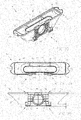
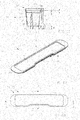
- Figures 2 to 17 show a trap 19 according to the invention which is suitable for the same purpose, more specifically for an assembly on the inside 2 of a water discharge tank 3 in a floor.
- the trap has an internal part 20 with a bottom 21 and an upstanding, internal wall 22.
- the internal part 20 is provided with an opening 23 for the supply of discharge water or discharge fluid.
- the trap 19 also contains a grille 24 intended to be mounted in the opening 23 on the internal part 20 in order to prevent oversized elements in the discharge water or discharge fluid from flowing through to the internal part 20.
- the trap 19 has an external part 25 in the form of a hood that serves as conductive element for the supply of discharge water or discharge fluid to the opening 23 on the internal part 20.
- the external part 25 contains a covering part 26 intended to extend over the internal part 20 after assembly.
- the covering part 26 extends after assembly over the opening 23 on the internal part 20 and this at a certain distance D thereof, which is shown in the cross-section of figure 6 .
- the discharge water or discharge fluid can flow under the covering part 26 to the grille 24 and the opening 23.
- the external part 25 also contains an external wall 27 which after assembly extends from the covering part 26 to a bottom edge 28.
- the bottom edge 28 is located at a certain height H above the bottom of the internal part 20, which is clearly illustrated in figure 5 , such that the discharge water or the discharge fluid can flow along this bottom edge 28 in the space 30 between the inside 31 of the external wall 27 and the outside 32 of the internal wall 22 to the opening 23 and the grille 24, which is made clear by means of figure 4 for example.
- the trap 19 according to the invention is special primarily because the covering part 26 of the external part 25 is made as a separate lid 33 that can be installed on the external wall 27 of the external part 25 in a removable way.
- the external part 25 of the trap 19 according to the invention is made in two parts, whereas the external part 9 in known traps 1 is a one-piece unit.
- the internal part 8 and the external part 9 are made as two separate elements, whereas in the embodiment of a trap 19 according to the invention 19, as is shown in figure 2 , the external wall 27 of the external part 25 and the internal wall 22 of the internal part 20 of the trap 19 are connected with each other in a fixed way.
- a special characteristic of the invention consists in that the trap 19 according to the invention contains a double-walled element 34 that is formed by the internal part 20 with the bottom 21 and the upstanding, internal wall 22 and whereby this internal part 20 is provided at the top with an opening 23 for a grille 24, whereby this internal part 20 is connected in a fixed way to an external wall 27 and whereby between the internal wall 22 and the external wall 27 there is a space 31 for the supply of discharge water or discharge fluid to the opening 23.
- This double-walled element 34 is sealable at the top with the lid 33.
- the lid 33 of the external part 25 is an essentially flat lid 33 and it has a shape that is complementary to the opening 35 formed by an edge 36 at the top 37 of the external wall 27.
- the lid 33 is provided on the bottom 38 with an edge 39 that can be fittingly affixed in the edge 36.
- lid 33 of the trap 19 is provided with retaining means 40 with which the grille 24 can be held in place in a detachable way.
- These retaining means 40 are such that by affixing the lid 33 on the external wall 27 the grille 24 is fittingly affixed in the opening 23 of the internal part 20.
- the grille 24 is in this case more or less oval-shaped according to the contours formed by an upstanding edge 41 on the internal part 20 which delimits the opening 23.
- the grille 24 is hereby formed by an oval-shaped outer edge 42 between which ribs 43 are provided.
- the grille has a thickness T corresponding to the height T' of the aforementioned upstanding edge 41.
- the retaining means 40 on the lid 33 of the external part 25 are also formed by upstanding protrusions 44 which are affixed centrally in the plane of the lid 33 on the bottom 38 thereof.
- these protrusions 44 are provided with slots 46 in which ribs 43 of the grille 24 can be clicked tight in a detachable way.
- protrusions 44 are made with a length D' which corresponds with the distance D that needs to be bridged between the covering part 26 or therefore the lid 33 and the opening 23 in which the grille 24 needs to be placed.
- connection between the external wall 27 and the internal part of the double-walled element 34 is on the one hand realised by connecting pieces 47.
- the trap 19 on the other hand is also provided with an interesting characteristic, whereby more specifically the external wall 27 and the internal wall 22 come together on the level of a common wall part 48.
- a transit opening 49 is provided intended to realise the connection between the space 50 in the internal part 20 and said drain pipe 6 of the tank 3.
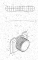
- the trap 19 is also provided with a separate connecting piece 51.
- This connecting piece 51 is essentially formed by a pipe section 52 which on one end 53 is provided with a flange 54.
- the pipe section 52 is provided with exterior screw thread 55 which can co-operate with the internal screw thread provided in the drain pipe 6.
- the flange 54 has more or less rectangular contours and at the back 56 is practically flat.
- connection piece 51 is mounted against the common wall part 48, whereby the pipe section 52 is centred over the transit opening 49 in the common wall part 48 of the external wall 27 and the internal wall 22 of the trap 19.
- the external wall 27 of the external part 25 of the trap 19 or more exactly the common wall part 48 and the connecting piece 51 are provided with complementary connecting parts 57 which are intended to attach the flange 54 of the connecting piece 51 in a detachable way to the external part 25 of the trap 19 and this in a way that the flange 54 is pressed against the external part 25 of the trap 19.
- These complementary connecting parts 57 are formed on the one hand by a pair of oblong openings 58 provided in an edge 59 protruding from the plane of the external part 25 of the trap 19.
- This protruding edge 59 extends over the width of the common wall part 48 to the top 37 thereof.
- two protrusions 60 on the flange 54 of the connecting piece 51 form parts 57 that are complementary to these oblong openings 58.
- the two protrusions 60 on the flange 54 are provided on the top corners 61 of the flange 54 and they extend in the extension of the plane of the flange 54.
- protrusions 60 can be fittingly inserted in the oblong openings 58 by an upward shift of the flange 54 over the common wall part 48.
- the two opposite side edges 64 of the rectangular contours of the flange 54 can be fittingly inserted between these hooks 63 for a movement of the flange 54 over the external wall 27 or the common wall part 48.
- the flange 54 is provided with raised parts 66 from the plane of the flange 54 which form complementary parts 57 on the hooks 63.
- these raised parts 66 are provided on the positions of the flange 54 that are caught between the hooks 63 on the external wall 27 of the trap 19, when the flange 54 is installed in the correct location for the alignment of the pipe section 52 of the connecting piece 51 with the transit opening 49 in the trap 19.
- This embodiment offers the major advantage that the connecting piece 51 can be detached many times and reconnected to the trap 19 without significant wear and tear occurring, as the connecting piece 51 is only tightened to the trap 19 during the assembly at the very last moment on the level of the hooks 63 and the raised parts 65.
- a seal on the connecting piece is shifted over the whole length until the connecting piece is in the right position, which obviously puts a great burden on the seal, resulting in premature damage to the seal.
- the raised parts 66 in the embodiment of the figures are realised by making the corners 65 kinked.
- sealing rings 67 and 68 to ensure a watertight sealing of the parts.
- the present invention is by no means limited to the embodiments described as an example of a trap 19 according to the invention, but such trap 19, can be realised in all kinds of other forms and dimensions without departing from the scope of the appended claims.
Landscapes
- Health & Medical Sciences (AREA)
- Life Sciences & Earth Sciences (AREA)
- Engineering & Computer Science (AREA)
- Hydrology & Water Resources (AREA)
- Public Health (AREA)
- Water Supply & Treatment (AREA)
- Sink And Installation For Waste Water (AREA)
Claims (11)
- Piège (19) qui est approprié pour son utilisation dans un réservoir d'écoulement d'eau (3) ; dans lequel le piège (19) est destiné à être monté dans le réservoir (3) et à être relié à une ouverture (4) pratiquée dans une paroi (5) du réservoir (3) ; dans lequel, en outre, le piège (19) est au moins muni des éléments repris ci-après :- une partie interne (20) comprenant une base (21) et une paroi interne verticale (22) ; dans lequel la partie interne (20) opposée à la base (21) est munie d'une ouverture (23) pour l'acheminement d'eau d'évacuation ou d'un fluide d'évacuation ;- une partie externe (25) sous la forme d'un capot qui fait office d'élément conducteur pour l'acheminement de l'eau d'évacuation ou du fluide d'évacuation dans la direction de l'ouverture (23) sur la partie interne (20) ;- un élément (26) de la partie externe (25) faisant office de recouvrement, destiné à s'étendre par-dessus la partie interne (20) après le montage et par-dessus l'ouverture (23) sur la partie interne (20) et ceci à une certaine distance (D) de ladite ouverture ;- une paroi externe (27) de la partie externe (25) qui s'étend à partir de l'élément (26) faisant office de recouvrement jusqu'à un bord (28), et de manière telle que cette paroi externe (27) après le montage, entoure une partie (29) de la paroi interne (20) ;- une grille (24) destinée à être montée dans l'ouverture (23) sur la partie interne (20) dans le but d'empêcher des éléments surdimensionnés dans l'eau d'évacuation ou dans le fluide d'évacuation de s'écouler à travers elle en direction de la partie interne (20) ;caractérisé
en ce que l'élément (26) de la partie externe, faisant office de recouvrement est réalisé sous la forme d'un couvercle séparé (33) qui peut être fixé d'une manière amovible sur la paroi externe (27) de la partie externe (25) ; et
en ce que ledit couvercle (33) est muni de moyens de retenue (40) avec lesquels la grille (24) peut être maintenue en place d'une manière amovible ; dans lequel, en fixant le couvercle (33) sur la paroi externe (27), la grille (24) est fixée de manière appropriée dans l'ouverture (23) de la partie interne (20). - Piège (19) selon la revendication 1, caractérisé en ce que le couvercle (33) de la partie externe (25) représente un couvercle essentiellement plat (33) qui possède une configuration dont la forme est complémentaire à celle de l'ouverture (35) réalisée à l'intervention d'un bord (36) au sommet (37) de la paroi externe (27).
- Piège (19) selon l'une quelconque des revendications précédentes, caractérisé en ce que les moyens de retenue (40) sur le couvercle (33) de la partie externe (25) sont réalisés à l'intervention de protrusions (44) sur le couvercle (33), qui sont munies de fentes (46) dans lesquelles des nervures (43) de la grille (24) peuvent être fermement insérées par encliquetage d'une manière amovible.
- Piège (19) selon l'une quelconque des revendications précédentes, caractérisé en ce que la paroi externe (27) de la partie externe (25) et la paroi interne (22) de la partie interne (20) du piège (19) sont reliées l'une à l'autre de manière inamovible.
- Piège (19) selon l'une quelconque des revendications précédentes, caractérisé en ce que la paroi externe (27) et la paroi interne (22) se rencontrent au niveau d'une partie de paroi commune (48) ; dans lequel, dans cette partie de paroi commune (48), une ouverture de transit (49) est prévue, destinée à la liaison audit tuyau d'évacuation (6) du réservoir (3).
- Piège (19) selon l'une quelconque des revendications précédentes, caractérisé en ce que la paroi interne (22) de la partie interne (20) et la paroi externe (25) de la partie externe (27) sont chacune munies d'une ouverture de transit destinée à la liaison audit tuyau d'évacuation (6) du réservoir (3).
- Piège (19) selon l'une quelconque des revendications précédentes, caractérisé en ce que le piège (19) est également muni d'une pièce de liaison séparée (51) destinée à relier le piège (19) à un tuyau d'évacuation (6) du réservoir (3) ; dans lequel la pièce de liaison est essentiellement réalisée à l'intervention d'un tronçon de tuyau (52) qui, à une extrémité (53), est muni d'une bride (54).
- Piège (19) selon les revendications 5 et 7, caractérisé en ce que la pièce de liaison (51) est conçue à des fins de montage ; dans lequel le tronçon de tuyau (52) est centré sur l'ouverture de transit (49) dans la partie de paroi commune (48) de la paroi externe (27) et de la paroi interne (22) du piège (19).
- Piège (19) selon la revendication 7 ou 8, caractérisé en ce que la paroi externe (27) de la partie externe (25) du piège (19) et la pièce de liaison (51) sont munies de pièces de liaison complémentaires (57) destinées à permettre la fixation de la bride (54) de la pièce de liaison (51) d'une manière amovible à la partie externe (25) du piège (19) et ceci d'une manière telle que la bride (54) est pressée contre la partie externe (25) du piège (19).
- Piège (19) selon la revendication 9, caractérisé en ce que la bride (54) représente une bride (54) essentiellement plate comprenant des contours rectangulaires et en ce que les pièces de liaison complémentaires (57) contiennent les éléments suivants :- une paire d'ouvertures oblongues (58) prévues dans un bord (59) faisant saillie par rapport au plan de la partie externe (25) du piège (19), dans lesquelles deux protrusions (60) sur la bride (54) de la pièce de liaison (51), qui s'étendent sur l'étendue du plan de la bride (54), peuvent être insérées d'une manière appropriée ;- deux crochets (63) prévus sur la paroi externe (27) du piège (19), qui se font mutuellement face et entre lesquels les deux bords latéraux (64) des contours rectangulaires de la bride (54) peuvent être fixés d'une manière appropriée pour un mouvement de la bride (54) par-dessus la paroi externe (27).
- Piège (19) selon la revendication 10, caractérisé en ce que la bride (54) est munie d'éléments surélevés (66) par rapport à la bride (54) et ceci aux endroits de la bride (54) qui sont saisis entre les crochets (63) sur la paroi externe (27) du piège (19) lorsque la bride (54) est montée à l'endroit correct pour l'alignement du tronçon de tuyau (52) de la pièce de liaison (51) avec l'ouverture de transit (49) dans le piège (19).
Priority Applications (1)
| Application Number | Priority Date | Filing Date | Title |
|---|---|---|---|
| PL18170303T PL3401453T3 (pl) | 2017-05-08 | 2018-05-02 | Syfon |
Applications Claiming Priority (1)
| Application Number | Priority Date | Filing Date | Title |
|---|---|---|---|
| BE2017/5329A BE1025200B1 (nl) | 2017-05-08 | 2017-05-08 | Sifon |
Publications (2)
| Publication Number | Publication Date |
|---|---|
| EP3401453A1 EP3401453A1 (fr) | 2018-11-14 |
| EP3401453B1 true EP3401453B1 (fr) | 2020-06-10 |
Family
ID=58992546
Family Applications (1)
| Application Number | Title | Priority Date | Filing Date |
|---|---|---|---|
| EP18170303.4A Active EP3401453B1 (fr) | 2017-05-08 | 2018-05-02 | Siphon hydraulique |
Country Status (3)
| Country | Link |
|---|---|
| EP (1) | EP3401453B1 (fr) |
| BE (1) | BE1025200B1 (fr) |
| PL (1) | PL3401453T3 (fr) |
Families Citing this family (1)
| Publication number | Priority date | Publication date | Assignee | Title |
|---|---|---|---|---|
| BE1032022B1 (nl) * | 2023-10-02 | 2025-04-28 | Carrodrain | Afvoergootsamenstel, afvoerlichaam voor gebruik in een dergelijk samenstel en reukslot voor gebruik in een dergelijk samenstel |
Family Cites Families (4)
| Publication number | Priority date | Publication date | Assignee | Title |
|---|---|---|---|---|
| DE502004000983D1 (de) * | 2004-03-04 | 2006-08-31 | Kessel Gmbh | Abwasserablauf |
| WO2014121465A1 (fr) * | 2013-02-06 | 2014-08-14 | 开平市新明光五金制品有限公司 | Récipient à déchets pour siphon de sol |
| NL1040270C2 (nl) * | 2013-06-25 | 2015-01-05 | R In T Groen Holding B V | Sifonstelsel. |
| BE1022376B1 (nl) * | 2014-11-03 | 2016-03-18 | De Denkfabriek Bvba | Afvoergootsamenstel, afvoerlichaam voor gebruik in een dergelijk samenstel en reukslot voor gebruik in een dergelijk samenstel |
-
2017
- 2017-05-08 BE BE2017/5329A patent/BE1025200B1/nl active IP Right Grant
-
2018
- 2018-05-02 EP EP18170303.4A patent/EP3401453B1/fr active Active
- 2018-05-02 PL PL18170303T patent/PL3401453T3/pl unknown
Non-Patent Citations (1)
| Title |
|---|
| None * |
Also Published As
| Publication number | Publication date |
|---|---|
| PL3401453T3 (pl) | 2021-05-04 |
| EP3401453A1 (fr) | 2018-11-14 |
| BE1025200A1 (nl) | 2018-12-04 |
| BE1025200B1 (nl) | 2018-12-12 |
Similar Documents
| Publication | Publication Date | Title |
|---|---|---|
| KR102059569B1 (ko) | 배수관 연결구 및 이를 포함하는 배수트랩 | |
| EP3215684B1 (fr) | Ensemble de vidange, corps de vidange pour une utilisation dans un tel ensemble et piège à odeurs pour une utilisation dans un tel ensemble | |
| KR101493605B1 (ko) | 배수체 | |
| CN107119767A (zh) | 一种里外防臭下水管 | |
| EP3401453B1 (fr) | Siphon hydraulique | |
| EP3931403B1 (fr) | Siphon anti-odeur avec clapet flexible | |
| JP4066011B2 (ja) | 床排水トラップ | |
| EP2754764B1 (fr) | Siphon avec joint flexible | |
| EP2674537B1 (fr) | Bouche d'égout à siphon | |
| KR101935790B1 (ko) | 싱크대용 배수장치 | |
| US20170051482A1 (en) | Trap integrated drain device for washbasin | |
| KR102007220B1 (ko) | 기밀성 및 내구성을 높인 배수유입관의 구조와 탈 부착형 악취차단 구조를 갖는 배수조 | |
| JP3911588B2 (ja) | 吸気弁付き排水トラップ | |
| EP2884016B1 (fr) | Drain à siphon | |
| JP5901594B2 (ja) | 排水トラップ | |
| KR20170003867U (ko) | 트랩형 멀티연결기구 | |
| KR20160003178U (ko) | 싱크대 배수호스 연결장치 | |
| AU2007200569A1 (en) | Device for a sliding door frame | |
| KR200333411Y1 (ko) | 악취역류방지장치 | |
| JP6060327B2 (ja) | 排水トラップ | |
| KR20210131203A (ko) | 배수관 연결장치 및 이를 포함하는 배수관 조립체 | |
| KR200446680Y1 (ko) | 냄새역류방지를 위한 배수관 연결장치 | |
| SU1153838A3 (ru) | Водоспускной бак | |
| CN222435476U (zh) | 一种适用于空调冷凝水排放的地漏 | |
| EP4343069A1 (fr) | Piège à odeurs |
Legal Events
| Date | Code | Title | Description |
|---|---|---|---|
| PUAI | Public reference made under article 153(3) epc to a published international application that has entered the european phase |
Free format text: ORIGINAL CODE: 0009012 |
|
| STAA | Information on the status of an ep patent application or granted ep patent |
Free format text: STATUS: THE APPLICATION HAS BEEN PUBLISHED |
|
| AK | Designated contracting states |
Kind code of ref document: A1 Designated state(s): AL AT BE BG CH CY CZ DE DK EE ES FI FR GB GR HR HU IE IS IT LI LT LU LV MC MK MT NL NO PL PT RO RS SE SI SK SM TR |
|
| AX | Request for extension of the european patent |
Extension state: BA ME |
|
| STAA | Information on the status of an ep patent application or granted ep patent |
Free format text: STATUS: REQUEST FOR EXAMINATION WAS MADE |
|
| 17P | Request for examination filed |
Effective date: 20190514 |
|
| RBV | Designated contracting states (corrected) |
Designated state(s): AL AT BE BG CH CY CZ DE DK EE ES FI FR GB GR HR HU IE IS IT LI LT LU LV MC MK MT NL NO PL PT RO RS SE SI SK SM TR |
|
| GRAP | Despatch of communication of intention to grant a patent |
Free format text: ORIGINAL CODE: EPIDOSNIGR1 |
|
| STAA | Information on the status of an ep patent application or granted ep patent |
Free format text: STATUS: GRANT OF PATENT IS INTENDED |
|
| INTG | Intention to grant announced |
Effective date: 20200115 |
|
| GRAS | Grant fee paid |
Free format text: ORIGINAL CODE: EPIDOSNIGR3 |
|
| GRAA | (expected) grant |
Free format text: ORIGINAL CODE: 0009210 |
|
| STAA | Information on the status of an ep patent application or granted ep patent |
Free format text: STATUS: THE PATENT HAS BEEN GRANTED |
|
| AK | Designated contracting states |
Kind code of ref document: B1 Designated state(s): AL AT BE BG CH CY CZ DE DK EE ES FI FR GB GR HR HU IE IS IT LI LT LU LV MC MK MT NL NO PL PT RO RS SE SI SK SM TR |
|
| REG | Reference to a national code |
Ref country code: GB Ref legal event code: FG4D |
|
| REG | Reference to a national code |
Ref country code: CH Ref legal event code: EP Ref country code: AT Ref legal event code: REF Ref document number: 1279312 Country of ref document: AT Kind code of ref document: T Effective date: 20200615 |
|
| REG | Reference to a national code |
Ref country code: DE Ref legal event code: R096 Ref document number: 602018005147 Country of ref document: DE |
|
| REG | Reference to a national code |
Ref country code: IE Ref legal event code: FG4D |
|
| REG | Reference to a national code |
Ref country code: CH Ref legal event code: NV Representative=s name: ORITI PATENTS - FRANCO ORITI, CH |
|
| REG | Reference to a national code |
Ref country code: NL Ref legal event code: FP |
|
| REG | Reference to a national code |
Ref country code: SE Ref legal event code: TRGR |
|
| REG | Reference to a national code |
Ref country code: LT Ref legal event code: MG4D |
|
| PG25 | Lapsed in a contracting state [announced via postgrant information from national office to epo] |
Ref country code: LT Free format text: LAPSE BECAUSE OF FAILURE TO SUBMIT A TRANSLATION OF THE DESCRIPTION OR TO PAY THE FEE WITHIN THE PRESCRIBED TIME-LIMIT Effective date: 20200610 Ref country code: NO Free format text: LAPSE BECAUSE OF FAILURE TO SUBMIT A TRANSLATION OF THE DESCRIPTION OR TO PAY THE FEE WITHIN THE PRESCRIBED TIME-LIMIT Effective date: 20200910 Ref country code: GR Free format text: LAPSE BECAUSE OF FAILURE TO SUBMIT A TRANSLATION OF THE DESCRIPTION OR TO PAY THE FEE WITHIN THE PRESCRIBED TIME-LIMIT Effective date: 20200911 Ref country code: FI Free format text: LAPSE BECAUSE OF FAILURE TO SUBMIT A TRANSLATION OF THE DESCRIPTION OR TO PAY THE FEE WITHIN THE PRESCRIBED TIME-LIMIT Effective date: 20200610 |
|
| PG25 | Lapsed in a contracting state [announced via postgrant information from national office to epo] |
Ref country code: LV Free format text: LAPSE BECAUSE OF FAILURE TO SUBMIT A TRANSLATION OF THE DESCRIPTION OR TO PAY THE FEE WITHIN THE PRESCRIBED TIME-LIMIT Effective date: 20200610 Ref country code: HR Free format text: LAPSE BECAUSE OF FAILURE TO SUBMIT A TRANSLATION OF THE DESCRIPTION OR TO PAY THE FEE WITHIN THE PRESCRIBED TIME-LIMIT Effective date: 20200610 Ref country code: RS Free format text: LAPSE BECAUSE OF FAILURE TO SUBMIT A TRANSLATION OF THE DESCRIPTION OR TO PAY THE FEE WITHIN THE PRESCRIBED TIME-LIMIT Effective date: 20200610 Ref country code: BG Free format text: LAPSE BECAUSE OF FAILURE TO SUBMIT A TRANSLATION OF THE DESCRIPTION OR TO PAY THE FEE WITHIN THE PRESCRIBED TIME-LIMIT Effective date: 20200910 |
|
| REG | Reference to a national code |
Ref country code: AT Ref legal event code: MK05 Ref document number: 1279312 Country of ref document: AT Kind code of ref document: T Effective date: 20200610 |
|
| PG25 | Lapsed in a contracting state [announced via postgrant information from national office to epo] |
Ref country code: AL Free format text: LAPSE BECAUSE OF FAILURE TO SUBMIT A TRANSLATION OF THE DESCRIPTION OR TO PAY THE FEE WITHIN THE PRESCRIBED TIME-LIMIT Effective date: 20200610 |
|
| PG25 | Lapsed in a contracting state [announced via postgrant information from national office to epo] |
Ref country code: RO Free format text: LAPSE BECAUSE OF FAILURE TO SUBMIT A TRANSLATION OF THE DESCRIPTION OR TO PAY THE FEE WITHIN THE PRESCRIBED TIME-LIMIT Effective date: 20200610 Ref country code: CZ Free format text: LAPSE BECAUSE OF FAILURE TO SUBMIT A TRANSLATION OF THE DESCRIPTION OR TO PAY THE FEE WITHIN THE PRESCRIBED TIME-LIMIT Effective date: 20200610 Ref country code: PT Free format text: LAPSE BECAUSE OF FAILURE TO SUBMIT A TRANSLATION OF THE DESCRIPTION OR TO PAY THE FEE WITHIN THE PRESCRIBED TIME-LIMIT Effective date: 20201012 Ref country code: ES Free format text: LAPSE BECAUSE OF FAILURE TO SUBMIT A TRANSLATION OF THE DESCRIPTION OR TO PAY THE FEE WITHIN THE PRESCRIBED TIME-LIMIT Effective date: 20200610 Ref country code: IT Free format text: LAPSE BECAUSE OF FAILURE TO SUBMIT A TRANSLATION OF THE DESCRIPTION OR TO PAY THE FEE WITHIN THE PRESCRIBED TIME-LIMIT Effective date: 20200610 Ref country code: AT Free format text: LAPSE BECAUSE OF FAILURE TO SUBMIT A TRANSLATION OF THE DESCRIPTION OR TO PAY THE FEE WITHIN THE PRESCRIBED TIME-LIMIT Effective date: 20200610 Ref country code: EE Free format text: LAPSE BECAUSE OF FAILURE TO SUBMIT A TRANSLATION OF THE DESCRIPTION OR TO PAY THE FEE WITHIN THE PRESCRIBED TIME-LIMIT Effective date: 20200610 Ref country code: SM Free format text: LAPSE BECAUSE OF FAILURE TO SUBMIT A TRANSLATION OF THE DESCRIPTION OR TO PAY THE FEE WITHIN THE PRESCRIBED TIME-LIMIT Effective date: 20200610 |
|
| PG25 | Lapsed in a contracting state [announced via postgrant information from national office to epo] |
Ref country code: SK Free format text: LAPSE BECAUSE OF FAILURE TO SUBMIT A TRANSLATION OF THE DESCRIPTION OR TO PAY THE FEE WITHIN THE PRESCRIBED TIME-LIMIT Effective date: 20200610 Ref country code: IS Free format text: LAPSE BECAUSE OF FAILURE TO SUBMIT A TRANSLATION OF THE DESCRIPTION OR TO PAY THE FEE WITHIN THE PRESCRIBED TIME-LIMIT Effective date: 20201010 |
|
| REG | Reference to a national code |
Ref country code: DE Ref legal event code: R097 Ref document number: 602018005147 Country of ref document: DE |
|
| PLBE | No opposition filed within time limit |
Free format text: ORIGINAL CODE: 0009261 |
|
| STAA | Information on the status of an ep patent application or granted ep patent |
Free format text: STATUS: NO OPPOSITION FILED WITHIN TIME LIMIT |
|
| PG25 | Lapsed in a contracting state [announced via postgrant information from national office to epo] |
Ref country code: DK Free format text: LAPSE BECAUSE OF FAILURE TO SUBMIT A TRANSLATION OF THE DESCRIPTION OR TO PAY THE FEE WITHIN THE PRESCRIBED TIME-LIMIT Effective date: 20200610 |
|
| 26N | No opposition filed |
Effective date: 20210311 |
|
| PG25 | Lapsed in a contracting state [announced via postgrant information from national office to epo] |
Ref country code: SI Free format text: LAPSE BECAUSE OF FAILURE TO SUBMIT A TRANSLATION OF THE DESCRIPTION OR TO PAY THE FEE WITHIN THE PRESCRIBED TIME-LIMIT Effective date: 20200610 |
|
| PG25 | Lapsed in a contracting state [announced via postgrant information from national office to epo] |
Ref country code: MC Free format text: LAPSE BECAUSE OF FAILURE TO SUBMIT A TRANSLATION OF THE DESCRIPTION OR TO PAY THE FEE WITHIN THE PRESCRIBED TIME-LIMIT Effective date: 20200610 |
|
| PGFP | Annual fee paid to national office [announced via postgrant information from national office to epo] |
Ref country code: SE Payment date: 20230321 Year of fee payment: 6 |
|
| P01 | Opt-out of the competence of the unified patent court (upc) registered |
Effective date: 20230331 |
|
| PG25 | Lapsed in a contracting state [announced via postgrant information from national office to epo] |
Ref country code: CY Free format text: LAPSE BECAUSE OF FAILURE TO SUBMIT A TRANSLATION OF THE DESCRIPTION OR TO PAY THE FEE WITHIN THE PRESCRIBED TIME-LIMIT Effective date: 20200610 |
|
| PG25 | Lapsed in a contracting state [announced via postgrant information from national office to epo] |
Ref country code: HU Free format text: LAPSE BECAUSE OF FAILURE TO SUBMIT A TRANSLATION OF THE DESCRIPTION OR TO PAY THE FEE WITHIN THE PRESCRIBED TIME-LIMIT; INVALID AB INITIO Effective date: 20180502 |
|
| PGFP | Annual fee paid to national office [announced via postgrant information from national office to epo] |
Ref country code: CH Payment date: 20230602 Year of fee payment: 6 |
|
| PG25 | Lapsed in a contracting state [announced via postgrant information from national office to epo] |
Ref country code: MK Free format text: LAPSE BECAUSE OF FAILURE TO SUBMIT A TRANSLATION OF THE DESCRIPTION OR TO PAY THE FEE WITHIN THE PRESCRIBED TIME-LIMIT Effective date: 20200610 |
|
| PG25 | Lapsed in a contracting state [announced via postgrant information from national office to epo] |
Ref country code: TR Free format text: LAPSE BECAUSE OF FAILURE TO SUBMIT A TRANSLATION OF THE DESCRIPTION OR TO PAY THE FEE WITHIN THE PRESCRIBED TIME-LIMIT Effective date: 20200610 |
|
| PG25 | Lapsed in a contracting state [announced via postgrant information from national office to epo] |
Ref country code: MT Free format text: LAPSE BECAUSE OF FAILURE TO SUBMIT A TRANSLATION OF THE DESCRIPTION OR TO PAY THE FEE WITHIN THE PRESCRIBED TIME-LIMIT Effective date: 20200610 |
|
| REG | Reference to a national code |
Ref country code: CH Ref legal event code: PL |
|
| REG | Reference to a national code |
Ref country code: SE Ref legal event code: EUG |
|
| PG25 | Lapsed in a contracting state [announced via postgrant information from national office to epo] |
Ref country code: CH Free format text: LAPSE BECAUSE OF NON-PAYMENT OF DUE FEES Effective date: 20240531 |
|
| PGFP | Annual fee paid to national office [announced via postgrant information from national office to epo] |
Ref country code: NL Payment date: 20250522 Year of fee payment: 8 |
|
| PGFP | Annual fee paid to national office [announced via postgrant information from national office to epo] |
Ref country code: PL Payment date: 20250422 Year of fee payment: 8 Ref country code: DE Payment date: 20250519 Year of fee payment: 8 |
|
| PGFP | Annual fee paid to national office [announced via postgrant information from national office to epo] |
Ref country code: LU Payment date: 20250520 Year of fee payment: 8 Ref country code: BE Payment date: 20250520 Year of fee payment: 8 |
|
| PGFP | Annual fee paid to national office [announced via postgrant information from national office to epo] |
Ref country code: FR Payment date: 20250521 Year of fee payment: 8 |
|
| PGFP | Annual fee paid to national office [announced via postgrant information from national office to epo] |
Ref country code: IE Payment date: 20250522 Year of fee payment: 8 |
|
| PG25 | Lapsed in a contracting state [announced via postgrant information from national office to epo] |
Ref country code: SE Free format text: LAPSE BECAUSE OF NON-PAYMENT OF DUE FEES Effective date: 20240503 |
|
| PGFP | Annual fee paid to national office [announced via postgrant information from national office to epo] |
Ref country code: GB Payment date: 20260327 Year of fee payment: 9 |