EP3401479A1 - Dispositif de déplacement d'une partie de meuble logée sur un corps d'un meuble - Google Patents
Dispositif de déplacement d'une partie de meuble logée sur un corps d'un meuble Download PDFInfo
- Publication number
- EP3401479A1 EP3401479A1 EP18171513.7A EP18171513A EP3401479A1 EP 3401479 A1 EP3401479 A1 EP 3401479A1 EP 18171513 A EP18171513 A EP 18171513A EP 3401479 A1 EP3401479 A1 EP 3401479A1
- Authority
- EP
- European Patent Office
- Prior art keywords
- furniture
- bearing
- furniture part
- movable
- fitting
- Prior art date
- Legal status (The legal status is an assumption and is not a legal conclusion. Google has not performed a legal analysis and makes no representation as to the accuracy of the status listed.)
- Granted
Links
Images


Classifications
-
- E—FIXED CONSTRUCTIONS
- E05—LOCKS; KEYS; WINDOW OR DOOR FITTINGS; SAFES
- E05F—DEVICES FOR MOVING WINGS INTO OPEN OR CLOSED POSITION; CHECKS FOR WINGS; WING FITTINGS NOT OTHERWISE PROVIDED FOR, CONCERNED WITH THE FUNCTIONING OF THE WING
- E05F1/00—Closers or openers for wings, not otherwise provided for in this subclass
- E05F1/08—Closers or openers for wings, not otherwise provided for in this subclass spring-actuated, e.g. for horizontally sliding wings
- E05F1/10—Closers or openers for wings, not otherwise provided for in this subclass spring-actuated, e.g. for horizontally sliding wings for swinging wings, e.g. counterbalance
- E05F1/1041—Closers or openers for wings, not otherwise provided for in this subclass spring-actuated, e.g. for horizontally sliding wings for swinging wings, e.g. counterbalance with a coil spring perpendicular to the pivot axis
- E05F1/105—Closers or openers for wings, not otherwise provided for in this subclass spring-actuated, e.g. for horizontally sliding wings for swinging wings, e.g. counterbalance with a coil spring perpendicular to the pivot axis with a compression spring
- E05F1/1058—Closers or openers for wings, not otherwise provided for in this subclass spring-actuated, e.g. for horizontally sliding wings for swinging wings, e.g. counterbalance with a coil spring perpendicular to the pivot axis with a compression spring for counterbalancing
-
- E—FIXED CONSTRUCTIONS
- E05—LOCKS; KEYS; WINDOW OR DOOR FITTINGS; SAFES
- E05D—HINGES OR SUSPENSION DEVICES FOR DOORS, WINDOWS OR WINGS
- E05D15/00—Suspension arrangements for wings
- E05D15/40—Suspension arrangements for wings supported on arms movable in vertical planes
- E05D15/46—Suspension arrangements for wings supported on arms movable in vertical planes with two pairs of pivoted arms
- E05D15/463—Suspension arrangements for wings supported on arms movable in vertical planes with two pairs of pivoted arms specially adapted for overhead wings
-
- E—FIXED CONSTRUCTIONS
- E05—LOCKS; KEYS; WINDOW OR DOOR FITTINGS; SAFES
- E05Y—INDEXING SCHEME ASSOCIATED WITH SUBCLASSES E05D AND E05F, RELATING TO CONSTRUCTION ELEMENTS, ELECTRIC CONTROL, POWER SUPPLY, POWER SIGNAL OR TRANSMISSION, USER INTERFACES, MOUNTING OR COUPLING, DETAILS, ACCESSORIES, AUXILIARY OPERATIONS NOT OTHERWISE PROVIDED FOR, APPLICATION THEREOF
- E05Y2600/00—Mounting or coupling arrangements for elements provided for in this subclass
- E05Y2600/50—Mounting methods; Positioning
- E05Y2600/56—Positioning, e.g. re-positioning, or pre-mounting
-
- E—FIXED CONSTRUCTIONS
- E05—LOCKS; KEYS; WINDOW OR DOOR FITTINGS; SAFES
- E05Y—INDEXING SCHEME ASSOCIATED WITH SUBCLASSES E05D AND E05F, RELATING TO CONSTRUCTION ELEMENTS, ELECTRIC CONTROL, POWER SUPPLY, POWER SIGNAL OR TRANSMISSION, USER INTERFACES, MOUNTING OR COUPLING, DETAILS, ACCESSORIES, AUXILIARY OPERATIONS NOT OTHERWISE PROVIDED FOR, APPLICATION THEREOF
- E05Y2900/00—Application of doors, windows, wings or fittings thereof
- E05Y2900/20—Application of doors, windows, wings or fittings thereof for furniture, e.g. cabinets
Definitions
- furniture sector guide means such as furniture hinges or flap fittings are known to move a furniture part relative to a furniture body can.
- the guide means must meet different requirements, in particular should be made accessible to the movement guide an interior of the furniture body or the movable furniture part to accommodate items in it or to be able to remove it.
- Known guide means are comparatively space-consuming, high or wide building, mounted on an inner surface of a side wall.
- the object of the present invention is to improve a device for moving a furniture part accommodated on a furniture carcass of a piece of furniture, in particular with regard to a compact, comparatively less bulky housing of the device on the furniture or to a material and / or assembly effort of the device to reduce.
- the invention is based on a device for moving a furniture part accommodated on a furniture carcass of a piece of furniture, in particular for moving a flap or furniture flap, wherein the device has guide means with which the furniture part is moved from a closed position to an open position relative to the furniture when the device is mounted on the furniture Furniture body and back is movable, wherein the guide means comprise a first and a second fitting, wherein arranged in the arranged state of the furniture, the first and the second fitting spaced from each other on the furniture body, wherein the device mounting means for attaching the first and the second fitting to the having movable furniture part, wherein the mounting means are mounted on the movable furniture part.
- the device is, for example, as a pivot fitting or flap fitting for e.g. formed an upper flap of a piece of furniture.
- the furniture is for example available as a hanging cabinet.
- the furniture part in the closed position occupies a maximally zoomed to a front side of the furniture body position.
- an opening of the furniture body in the closed position is at least partially closed.
- the first fitting can be arranged, for example, on a right side of the furniture body and the second fitting on a left side of the furniture body, for example, or vice versa.
- the first and / or the second fitting formed in a side wall of the furniture body, in particular in a recess of the side wall of the furniture body, used.
- the mounting means comprise a first mounting unit with a movable bearing and a second mounting unit with a fixed bearing, wherein in the assembled state on the furniture part, the two mounting units spaced from each other are mounted on the furniture part, and wherein arranged in the first fitting is coupled to the first mounting unit and the second fitting is coupled to the second mounting unit, so that in the mounted state of the device on furniture a position of the furniture part relative to the furniture body by adjustment means on the fixed bearing is tension-free adjustable by a positional displacement of the furniture part can be compensated by the floating bearing ,
- the floating bearing and / or the first fitting in an adjustment of the fixed bearing in the same direction, for. + x or -x moves, like the second fitting and / or the fixed bearing.
- the closing position of the furniture part relative to the furniture body is adjustable by the adjusting means.
- a tilting or distortion of a fitting or both fittings in a position adjustment of the furniture part is avoided by the advantageous embodiment of the invention.
- the fixed bearing is self-locking. As a result, an unintentional positional adjustment of the furniture part is avoided.
- the movable bearing is self-locking.
- the movable bearing is self-locking in an open position of the furniture part.
- the movable bearing is designed such that a self-locking of the movable bearing during an opening and / or closing movement of the furniture part, at least along a partial movement path, for example, in a range of movement about the closed position of the furniture part, is repealed.
- a self-locking of the movable bearing during an opening and / or closing movement of the furniture part at least along a partial movement path, for example, in a range of movement about the closed position of the furniture part, is repealed.
- a partial movement path for example, in a range of movement about the closed position of the furniture part
- the adjustment means are self-locking. As a result, an unintentional adjustment of the adjustment is avoided.
- the fitting and the mounting means are designed such that the fitting can be suspended from the mounting unit.
- the first fitting can be suspended from the first assembly unit and / or the second fitting can be suspended from the second assembly unit.
- the first and / or the second fitting is detachably connectable to the first and / or the second mounting unit.
- the fitting has a hook-shaped coupling element, which can be suspended from a corresponding counterpart of the mounting means. It is also conceivable that the fitting with the mounting means via a clamping and / or latching, e.g. can be connected via a clip-on connection.
- the movable bearing is formed in such a way that a game, in particular a game of motion, is present in two directions, in particular parallel to each other.
- the floating bearing is for example designed such that the first fitting arranged on the first fitting a game in the direction of the second fitting and / or opposite thereto.
- the movable bearing is present such that in the arranged state of the mounting means on the furniture part, the game direction is parallel to the furniture part.
- the movable bearing is designed such that a movement clearance or a freedom of movement of a arranged on the mounting unit of the floating bearing fitting is present perpendicular to a plane of movement of the fitting.
- the floating bearing has a degree of freedom of movement.
- the play of the movable bearing in particular the play of the floating bearing in a lateral direction relative to the furniture body, in a range between + 5mm and -5mm, between + 4mm and -4mm or between + 3mm and -3mm, in particular is the game of floating bearing in a range between + 2.5mm and -2.5mm.
- the floating bearing is designed as a slotted guide.
- the first fitting which is connectable to the first mounting unit, movably guided in the slotted guide.
- the floating bearing has a carriage bearing. It is also preferred that the movable bearing has a self-aligning bearing. As a result, the first fitting in the mounted state is movably coupled to the first mounting unit.
- Another advantage is also that the self-aligning bearing is designed as a multipend bearing.
- the self-aligning bearing is designed, for example, as a 2-point self-aligning bearing, a double-action pendulum bearing, a 3-point self-aligning bearing or a multiple-action pendulum bearing, in particular as a multipend bearing.
- a multi-or multipoint bearing is understood in particular a self-aligning bearing, which two or has more pendulum elements.
- a first pendulum element is for example movably mounted on a fixed component and another, eg second pendulum element is in particular each movably mounted on a preceding, eg the first pendulum element, etc.
- the first pendulum element with a particular single movably connected further pendulum element.
- each further pendulum is coupled in particular with exactly two further pendulum elements movable.
- a self-aligning bearing can be used both vertically hanging, using natural gravity, and / or lying horizontally.
- Pendulum elements of the pendulum bearing can thus e.g. be present hanging vertically and / or also e.g. lying horizontally.
- the pendulum bearing in particular has exactly two pendulum elements.
- the pendulum elements are designed for example as pendulum arms.
- a self-aligning bearing with two pendulum elements is e.g. 2-fold pendulum bearing called.
- the pendulum bearing in particular comprises exactly two pivot axes.
- the two pendulum elements connects a second pivot axis, the two pendulum elements movable, in particular pivotally with each other.
- the two pendulum elements are e.g. movable, e.g. pivotable, in particular to each other rotatable.
- a pendulum element is movable on a first pivot axis, in particular pivotally mounted on the mounting unit, e.g. arranged.
- the self-aligning bearing has a guide member with which a pendulum element is movably guided.
- the floating bearing comprises a slotted guide.
- the self-aligning bearing comprises two guide members.
- a first pendulum element is movably guided by a first guide member and / or by a second guide member.
- a second pendulum element is movably guided by the first guide member and / or by the second guide member.
- the self-aligning bearing comprises a plurality of guide elements, for example, the first guide element is designed to movably guide two or more pendulum elements, and a second guide element is adapted to guide a particular single pendulum element, in particular directly or directly movably.
- the movable bearing is designed such that a lateral and / or height adjustment of the fixed bearing by the movable bearing, in particular by the self-aligning bearing is compensated.
- the self-aligning bearing is present such that an adjustment of the fixed bearing in a direction parallel to a front side of the furniture body and / or a main plane of the movable furniture part can be compensated by the self-aligning bearing.
- a main plane of the movable furniture part is meant for example a rear side of the movable furniture part, which in the closed position is opposite a front side of the furniture body, e.g. Pending to the front of the furniture body, is present.
- the non-locating bearing, in particular the self-aligning bearing is designed such that an adjustment of the fixed bearing by the movable bearing, in particular by the self-aligning bearing, in two mutually perpendicular in particular spatial directions can be compensated.
- the self-aligning bearing of the floating bearing is independent of a height and / or depth adjustment of the movable bearing is present.
- the self-aligning bearing is present in such a way that the self-aligning bearing in particular allows only a lateral adjustment of the movable furniture part. Under a lateral adjustment is in particular a lateral change in position of the movable To understand furniture part in the closed position in a horizontal direction relative to the furniture body.
- the first pivot axis of the pendulum bearing is stationary relative to remaining parts of the movable bearing and a second pivot axis of the pendulum bearing movable relative to the remaining parts of the floating bearing.
- the first and the second pivot axis is formed on the first pendulum element.
- the first and the second pivot axis are spaced from one another on the first pendulum element.
- the first pivot axis connects e.g. the first pendulum element movable with remaining parts of the floating bearing.
- the second pivot axis connects, for example, the first and the second pendulum movable with each other.
- the non-locating bearing in particular the self-aligning bearing, is designed such that the first pivot axis in the arranged state of the device on the movable furniture part in an open position of the movable furniture part is further away from a front side of the furniture body, as the second pivot axis.
- the second pivot axis in the assembled state of the device on the furniture, is formed in the closed position in a vertical direction seen above the first pivot axis.
- the floating bearing is designed in such a way that a game exists in two directions.
- a game of the floating bearing in a game level exists.
- the game level is aligned at least approximately parallel to a front side of the furniture, in particular of the furniture part.
- the game level in the closed position of the movable furniture part is aligned at least approximately parallel to the front side of the furniture body and / or to the front side of the furniture part and / or to the back of the furniture part.
- the game plane aligned transversely, in particular perpendicular to a plane of movement of the guide means of the device.
- the fixed bearing is adjustably present in an open position of the furniture part, wherein a position of the furniture part relative to the second fitting is changed by an adjustment of the fixed bearing
- the floating bearing is designed such that in a closing movement of the furniture part from the open position in the closed position, a change in position of the furniture part relative to the first fitting is made possible, so that the furniture part coupled tension-free in a setting direction of the fixed bearing with the first and the second fitting.
- the floating bearing is present such that in the closed position, a change in position of the furniture part relative to the first fitting can be done so that the furniture part coupled tension-free in a setting direction of the fixed bearing with the first and the second fitting.
- an adjusting means is designed as an eccentric. It is also conceivable that an adjustment as a simple screw, as a screw adjustment and / or a slot is present.
- Fig. 1 shows in perspective an inventive furniture or a wall unit 1 with a box-shaped furniture body 2 and a furniture part received thereon, which is designed as a plate-like upper flap 3, which is shown in an open position relative to the furniture body 2.
- the furniture body 2 comprises two opposite, upright side walls 4 and 5, which are connected at the bottom with an underbody 6 and at the top with a topsoil 7.
- the back of the furniture body 2 is closed by a rear wall 8.
- a movement device designed as Oberklappenbeschlag 9.
- the upper flap fitting 9 has on the side wall 4, a first fitting unit 10 and on the side wall 5, a second fitting unit 11, which are similar but constructed side-related to the functionally correct arrangement on the respective side wall 4 and 5 respectively.
- Each fitting unit 10 and 11 comprises a base unit 12, guide means 13 with articulated levers and a mounting unit in the form of a mounting plate 15a, 15b.
- a swivel arm assembly 14 is the Base unit 12 with the mounting plate 15a, 15b, which is fixedly secured to an inner side of the upper flap 3, for example, sunk in a material recess 36.
- the guide means 13 an adjustable with an adjusting 17 energy storage 16 to support the opening movement of the upper flap 3 in the open position or open position and a damper device 18 for a damped closing movement of the upper flap 3 in the closed position or closed position.
- the base unit 12 is preferably formed from a sheet metal component and comprises a flat, flat or thin base plate 19 and a flat thin cover plate 20 opposite the base plate 19, which are only in the Fig. 1 and 2 is shown.
- an end portion 21 is present at the front side of the base unit 12, whose outer side is aligned transversely to the plane of the base plate 19.
- a rectangular recess 22 in the end portion 21 engage the respective pivot arms of the pivot arm assembly 14th
- the square in the base for example, or rectangular base plate 12 accordingly has four straight base plates edges 23 to 26, wherein in the embodiment shown at the two adjacent base plate edges 25 and 26 respectively to the plane of the base plate 19, for example, vertically upstanding rectangle - or strip-shaped wall portion 27, 28 is present.
- the wall sections 27, 28 are, for example, identical in their height, which is preferably smaller by a predeterminable measure than, for example, the thickness of the wall element of the furniture or of the side wall 4 of the upper cabinet 1, to which the base unit 12 of the fitting unit 10 is attached. If the side wall 4 has a usual thickness a of 16 millimeters (s. Fig. 2 For example, a height of the base unit 12 is preferably 12 millimeters or less, for example.
- the base unit 12 in a prepared material recess 31 are inserted flush or flush when the material recess 31 has a depth of 12 millimeters.
- the residual floor thickness of the material recess 31 is then 4 millimeters accordingly.
- the height of the base unit is in addition to the height of the wall portion 27, 28, for example, in addition to the thickness of the base plate 19 and the thickness of the abutment flange 29, 30 together. With an assumed sheet thickness of, for example, one millimeter and a height of the base unit 12 of 12 millimeters, the height of the wall section 27 or 28 is, for example, ten millimeters.
- investment flanges 29, 30 are present.
- the fitting unit 10 or the base unit 12 can be firmly attached to the side wall 4, in particular fixed in a fixed position and without play.
- the base unit 12 also contributes.
- surface contact via the surface contact of the outer side of the base unit 12 with the wall of the material recess 31 advantageously acts, which has a stabilizing effect.
- the adhesion may be enhanced by adhesives, e.g. an adhesive layer between the base unit 12 and the material recess 31 can be improved or increased.
- each wall portion 27 and 28 includes a right angle angled thereto abutment flange, ie on the wall portion 27 of the abutment flange 29 and the wall portion 28 of the abutment 30.
- the abutment flanges 29, 30 are also rectangular or strip-shaped, for example between 5 and 25 millimeters wide, preferably about 15 millimeters wide.
- the fastening means such as e.g. the screw means 40 engage by e.g. prepared through holes in the abutment flanges 29, 30th
- the rectangular flat end section 21 is flush-mounted to a front, narrow end face 4b of the side wall 4.
- a plane perpendicular to the plane of the base plate 19 is e.g. provided at right angles projecting wall portion 32, but without abutment flange, since the base plate edge 24 connects to the bottom bottom 7 on the underside.
- a screw 33 engages through an obliquely oriented passage opening in an angle element 34 and through an opening 35 in the wall section 32, so that the screw 33 can be screwed obliquely into the top floor 7, whereby the base unit 12 upwards and is attracted to the side wall 4.
- the mounting plate 15a, 15b is advantageously recessed in a corresponding material recess 36 in the upper flap 3, preferably housed flush with the inside of the upper flap 3.
- the fitting unit 10 or the base unit 12 can be attached to the furniture body 2 without a material recess (s. Fig. 8 ).
- a mounting unit 15a or 15b present, which, for example, to the special mounting position of Fitting unit 10 is adapted to the furniture body 2.
- FIG. 10 shows the upper portion of the upper cabinet 1 with the upper flap 3 open, the upper flap 3 is shown partially and the mounting plate 15a is shown completely cut. Accordingly, the mounting plate 15a is received in the matching material recess 36 almost completely sunk.
- the mounting plate 15a is comparable in basic form, for example, with the basic shape of the base unit 12 and has a flat base plate 42, a wall portion 43 projecting therefrom and an abutment flange 44 projecting at an angle to the outside on the wall portion 43.
- the material recess 36 comprises a deeper main pocket 36a and a flatter side pocket 36b in which the abutment flange 44 of the mounting plate 15a is received.
- adjusting means 45 are accommodated for adjusting the relative position between the pivot arm assembly 14 and the mounting plate 15a. From the swivel arm arrangement 14, a swivel arm 14.1 extends into the region of the mounting plate 15a.
- the adjustment means 45 of the mounting plate 15a include, for example, depth adjustment means 46 with e.g. a set screw 47, side adjustment means 48 with e.g. an eccentric 49 and / or height adjustment means 50 with e.g. an adjusting screw 51.
- FIGS. 14a-14c the mounting unit 15a is shown in different lateral adjustment position.
- Figure 14a is a maximally outwardly, in the direction of furniture cabinet side wall 4 adjusted mounting unit 15a shown in FIG FIG. 14b a middle position in which the mounting unit 15a is not subject to lateral adjustment and in FIG. 14c a maximally inward, in the direction of furniture body side wall 5 and in the direction of mounting unit 15b adjusted mounting unit 15a shown.
- the mounting unit 15a is equally adjustable in both directions by the soverstellstoff 48 from the center position, for example by a distance ⁇ x.
- the lateral adjustment of the mounting unit is done for example by turning the eccentric 49 by a user.
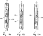
- the FIGS. 15a to 15c the mounting unit 15b is shown, which has a movable bearing 58.
- the movable bearing 58 of the mounting unit 15b is corresponding to the fixed bearing of the mounting unit 15a from a central position, shown in FIG. 15b adjustable in the lateral direction, advantageously in both lateral directions the same distance (shown in the FIGS. 15a and 15c ).
- the movable bearing 58 has the same lateral movement range ⁇ x, as the fixed bearing.
- a position of the second pivot arm assembly 14 provided on the furniture body 2 opposite the first pivot arm assembly 14 is simultaneously adjusted relative to the mounting unit 15b by moving the second swivel arm assembly 14 undergoes a change in position by the floating bearing 58. It is also conceivable that the floating bearing 58 is present as a self-aligning bearing.
- FIGS. 17a-17c is a further variant of a mounting unit 15a with a fixed bearing and the FIGS. 18a-18c is a further variant of a mounting unit 15b to remove with a floating bearing.
- the mounting units 15a and 15b of Figures 17 and 18 differ from the mounting units 15a and 15b of FIGS. 15 and 16 in that the assembly units 15a, 15b are formed on the one hand in a manner such that the assembly units can be mounted on the inner side 3a of the upper flap 3 and are not inserted or inserted in the upper flap 3.
- FIG. 16 can be seen that the base unit 12 are mounted on the side walls 4, 5 of the furniture body 2 and thus the pivot arm assembly 14 in comparison to the pivot arm assembly 14 of FIG.
- quick-connecting means 52 which comprises a pivotable locking lever 53 and a pin 54 close to the detent lever 53 and a further detent 53 spaced pin 55 on the pivot arm assembly 14, wherein the longitudinal axes of the pins 54, 55 parallel to the pivot axis of the Locking lever 53 run.
- the quick-connection means 52 comprise a latching nose 56 and a latching hook 57, which are designed to match the locking lever 53, the pin 54 and the pin 55.
- Dismantling is done by reversing the sequence of steps required for installation.
- FIG. 20 a further variant of a floating bearing 38 is shown, which has a self-aligning bearing 59.
- the self-aligning bearing 59 can advantageously be arranged on a base plate 39 of the floating bearing 38.
- the base plate 39 for example, the height adjustment means 50 and / or the Tiefenverstellstoff 46 can be arranged.
- the base plate 39 comprises parts of the height adjustment means 50 and / or the Tiefenverstellstoff 46th
- the pendulum bearing 59 includes, for example, two pendulum elements in the form of a first pendulum arm 60 and a second pendulum 61.
- the first pendulum 60 is pivotally mounted by means of a first pivot axis 62 to a base plate 39 of the floating bearing 38.
- the first pendulum arm 60 is pivotally coupled via a second pivot axis 63 to the second pendulum arm 61.
- a coupling member 66 can be arranged, which is adapted to be connectable to a coupling element of the swivel arm arrangement of the fitting.
- the two pendulum arms 60, 61 of the pendulum bearing 59 are advantageously arranged one above the other. As a result, a space requirement is advantageous reduced.
- the self-aligning bearing 59 comprises e.g. a first guide member 64 and / or a second guide member 65.
- the guide members 64, 65 spaced from each other and formed opposite to the pendulum bearing 59.
- the second guide member 65 of the pendulum bearing 59 is advantageously present such that it movably guides the first pendulum arm 60, so that the first pendulum arm 60 is mounted movably in a pendulum arm movement plane, in particular parallel to the inside 3a of the top flap 3, and a particularly comparatively large movement transversely is prevented to this Pendelarmbewegsebene. As a result, the first pendulum arm 60 is secured against tilting.
- the first guide member 64 of the pendulum bearing 59 is advantageously provided so that it movably guides the second pendulum arm 61, so that the second pendulum arm 61 in a further Pendelarmsammlungsebene longitudinally, in particular parallel to the inside 3a of the upper flap 3 is movably mounted and a particular comparatively large movement is prevented transversely to the Pendelarmbewegsebene.
- the first and / or the second pendulum arm 60, 61 are secured against tilting.
- a carriage-like mounting in particular a carriage mounting of the first and / or the second pendulum arm 60, 61 by the first and / or second guide member 64, 65 realized thereby.
- the second guide member 65 is advantageously in one piece on the floating bearing 38 available.
- the first guide member 64 is formed for example as a separate component.
- the first guide member 64 for example, by means of a connecting element 67, for example in the form of a screw, a rivet or a bolt on the floating bearing 38 can be attached.
- the connecting element 67 can, for example, simultaneously form a pivot axis 62, 63, in particular the first pivot axis 62 of the self-aligning bearing 59.
Landscapes
- Engineering & Computer Science (AREA)
- Mechanical Engineering (AREA)
- Hinges (AREA)
- Cabinets, Racks, Or The Like Of Rigid Construction (AREA)
Applications Claiming Priority (2)
| Application Number | Priority Date | Filing Date | Title |
|---|---|---|---|
| DE202017102808.9U DE202017102808U1 (de) | 2017-05-10 | 2017-05-10 | Vorrichtung zur Bewegung eines an einem Möbelkorpus eines Möbels aufgenommenen Möbelteils |
| DE102018109056.0A DE102018109056A1 (de) | 2017-05-10 | 2018-04-17 | Vorrichtung zur Bewegung eines an einem Möbelkorpus eines Möbels aufgenommenen Möbelteils |
Publications (2)
| Publication Number | Publication Date |
|---|---|
| EP3401479A1 true EP3401479A1 (fr) | 2018-11-14 |
| EP3401479B1 EP3401479B1 (fr) | 2023-09-06 |
Family
ID=62134136
Family Applications (1)
| Application Number | Title | Priority Date | Filing Date |
|---|---|---|---|
| EP18171513.7A Active EP3401479B1 (fr) | 2017-05-10 | 2018-05-09 | Ferrure d'abattant superieure pour un meuble |
Country Status (2)
| Country | Link |
|---|---|
| EP (1) | EP3401479B1 (fr) |
| ES (1) | ES2965238T3 (fr) |
Cited By (4)
| Publication number | Priority date | Publication date | Assignee | Title |
|---|---|---|---|---|
| WO2020232482A1 (fr) * | 2019-05-17 | 2020-11-26 | Julius Blum Gmbh | Ferrure pour meuble |
| WO2021001390A1 (fr) * | 2019-07-04 | 2021-01-07 | Paul Hettich Gmbh & Co. Kg | Plaque de meuble et meuble |
| RU2811094C2 (ru) * | 2019-07-04 | 2024-01-11 | Пауль Хеттих Гмбх Унд Ко. Кг | Мебельная панель и предмет мебели |
| WO2024050583A1 (fr) * | 2022-09-09 | 2024-03-14 | Julius Blum Gmbh | Dispositif d'entraînement pour meuble |
Citations (4)
| Publication number | Priority date | Publication date | Assignee | Title |
|---|---|---|---|---|
| JP2005105678A (ja) * | 2003-09-30 | 2005-04-21 | Bunka Shutter Co Ltd | 抜き差し型蝶番及びドアの蝶番構造 |
| DE102006060463B3 (de) * | 2006-12-19 | 2008-04-03 | Bartels Systembeschläge GmbH | Bandaufnahme mit integrierter Höhenverstellung für Türzargen zur Aufnahme von Rahmenteilen |
| WO2014161024A1 (fr) * | 2013-04-04 | 2014-10-09 | Rmd Industries Pty Ltd | Charnière réglable |
| JP2016044427A (ja) * | 2014-08-21 | 2016-04-04 | スガツネ工業株式会社 | ヒンジ |
-
2018
- 2018-05-09 ES ES18171513T patent/ES2965238T3/es active Active
- 2018-05-09 EP EP18171513.7A patent/EP3401479B1/fr active Active
Patent Citations (4)
| Publication number | Priority date | Publication date | Assignee | Title |
|---|---|---|---|---|
| JP2005105678A (ja) * | 2003-09-30 | 2005-04-21 | Bunka Shutter Co Ltd | 抜き差し型蝶番及びドアの蝶番構造 |
| DE102006060463B3 (de) * | 2006-12-19 | 2008-04-03 | Bartels Systembeschläge GmbH | Bandaufnahme mit integrierter Höhenverstellung für Türzargen zur Aufnahme von Rahmenteilen |
| WO2014161024A1 (fr) * | 2013-04-04 | 2014-10-09 | Rmd Industries Pty Ltd | Charnière réglable |
| JP2016044427A (ja) * | 2014-08-21 | 2016-04-04 | スガツネ工業株式会社 | ヒンジ |
Cited By (8)
| Publication number | Priority date | Publication date | Assignee | Title |
|---|---|---|---|---|
| WO2020232482A1 (fr) * | 2019-05-17 | 2020-11-26 | Julius Blum Gmbh | Ferrure pour meuble |
| US11970893B2 (en) | 2019-05-17 | 2024-04-30 | Julius Blum Gmbh | Furniture fitting |
| EP4365397A3 (fr) * | 2019-05-17 | 2024-08-07 | Julius Blum GmbH | Ferrure pour meuble |
| WO2021001390A1 (fr) * | 2019-07-04 | 2021-01-07 | Paul Hettich Gmbh & Co. Kg | Plaque de meuble et meuble |
| CN114096180A (zh) * | 2019-07-04 | 2022-02-25 | 保罗海蒂诗有限及两合公司 | 家具板和家具 |
| RU2811094C2 (ru) * | 2019-07-04 | 2024-01-11 | Пауль Хеттих Гмбх Унд Ко. Кг | Мебельная панель и предмет мебели |
| WO2024050583A1 (fr) * | 2022-09-09 | 2024-03-14 | Julius Blum Gmbh | Dispositif d'entraînement pour meuble |
| JP2025528530A (ja) * | 2022-09-09 | 2025-08-28 | ユリウス ブルーム ゲー・エム・ベー・ハー | 家具駆動装置 |
Also Published As
| Publication number | Publication date |
|---|---|
| EP3401479B1 (fr) | 2023-09-06 |
| ES2965238T3 (es) | 2024-04-11 |
Similar Documents
| Publication | Publication Date | Title |
|---|---|---|
| EP3401477B1 (fr) | Meuble | |
| EP3401476B1 (fr) | Dispositif de déplacement d'une partie de meuble logé sur un corps du meuble d'un meuble | |
| EP3561207B1 (fr) | Moyen de raccordement et partie de meuble | |
| EP3556978A1 (fr) | Dispositif de déplacement d'une partie de meuble logée sur une partie d'un meuble | |
| EP3561209A1 (fr) | Dispositif de déplacement d'une partie de meuble et meuble | |
| EP3401481B1 (fr) | Dispositif de déplacement d'une partie de meuble logée sur un corps de meuble et meuble | |
| DE102011056463B4 (de) | Gehäuse zum Aufnehmen von Bauteilen, insbesondere von elektronischen Baugruppen, Bauelementen und dergleichen | |
| EP3401479A1 (fr) | Dispositif de déplacement d'une partie de meuble logée sur un corps d'un meuble | |
| EP3401478A1 (fr) | Dispositif de déplacement d'une partie de meuble logée sur un corps d'un meuble | |
| EP3103948A1 (fr) | Penture pour une porte ou une fenêtre | |
| DE202011104559U1 (de) | Vorrichtung mit einer Anbringeinrichtung zur lösbaren Verbindung eines Frontteils einer Schublade mit einer Profilleiste sowie Möbel | |
| EP0096898B1 (fr) | Tiroir pour armoires | |
| DE202015102912U1 (de) | Wandelement für eine Schublade, Schublade und Möbel mit einer Schublade | |
| AT520767B1 (de) | Anordnung aus einem Auflagesteg für einen Schubladenboden und einer Haltevorrichtung | |
| DE202014104928U1 (de) | Vorrichtung zur Befestigung eines Frontbauteils an einem Anbringabschnitt eines Möbelteils, Möbelteil und Möbel | |
| EP3622143A1 (fr) | Charnière de meuble | |
| EP0262427A2 (fr) | Coffret de table pour dispositifs électrotechniques | |
| WO2020001841A1 (fr) | Ensemble d'une bande pour une liaison articulée avec charnière autour d'un axe de charnière d'un battant sur un cadre ainsi que bande pourvue de cet ensemble | |
| DE102018130012A1 (de) | Schubkasten und Möbel | |
| EP3704337B1 (fr) | Pièce de bande | |
| DE112021003269T5 (de) | Gestänge- und Scharnieranordnung mit mehreren hochbelastbaren Verstrebungen für schwenkbar gelagerte Ausstellfenster | |
| AT527477B1 (de) | Vorrichtung zum Halten einer Abtrennung | |
| DE20120238U1 (de) | Montageplatte zur verstellbaren Halterung von Möbelscharnieren am Korpus von Möbelstücken | |
| EP3556977B1 (fr) | Élément de cadre pour un cadre de meuble et meuble | |
| DE202012012133U1 (de) | Möbel und Anbringvorrichtung für eine Möbelfront an einem Möbel |
Legal Events
| Date | Code | Title | Description |
|---|---|---|---|
| PUAI | Public reference made under article 153(3) epc to a published international application that has entered the european phase |
Free format text: ORIGINAL CODE: 0009012 |
|
| STAA | Information on the status of an ep patent application or granted ep patent |
Free format text: STATUS: THE APPLICATION HAS BEEN PUBLISHED |
|
| AK | Designated contracting states |
Kind code of ref document: A1 Designated state(s): AL AT BE BG CH CY CZ DE DK EE ES FI FR GB GR HR HU IE IS IT LI LT LU LV MC MK MT NL NO PL PT RO RS SE SI SK SM TR |
|
| AX | Request for extension of the european patent |
Extension state: BA ME |
|
| STAA | Information on the status of an ep patent application or granted ep patent |
Free format text: STATUS: REQUEST FOR EXAMINATION WAS MADE |
|
| 17P | Request for examination filed |
Effective date: 20190325 |
|
| RAP1 | Party data changed (applicant data changed or rights of an application transferred) |
Owner name: GRASS GMBH |
|
| RBV | Designated contracting states (corrected) |
Designated state(s): AL AT BE BG CH CY CZ DE DK EE ES FI FR GB GR HR HU IE IS IT LI LT LU LV MC MK MT NL NO PL PT RO RS SE SI SK SM TR |
|
| STAA | Information on the status of an ep patent application or granted ep patent |
Free format text: STATUS: EXAMINATION IS IN PROGRESS |
|
| 17Q | First examination report despatched |
Effective date: 20210315 |
|
| GRAP | Despatch of communication of intention to grant a patent |
Free format text: ORIGINAL CODE: EPIDOSNIGR1 |
|
| STAA | Information on the status of an ep patent application or granted ep patent |
Free format text: STATUS: GRANT OF PATENT IS INTENDED |
|
| INTG | Intention to grant announced |
Effective date: 20230418 |
|
| GRAS | Grant fee paid |
Free format text: ORIGINAL CODE: EPIDOSNIGR3 |
|
| GRAA | (expected) grant |
Free format text: ORIGINAL CODE: 0009210 |
|
| STAA | Information on the status of an ep patent application or granted ep patent |
Free format text: STATUS: THE PATENT HAS BEEN GRANTED |
|
| AK | Designated contracting states |
Kind code of ref document: B1 Designated state(s): AL AT BE BG CH CY CZ DE DK EE ES FI FR GB GR HR HU IE IS IT LI LT LU LV MC MK MT NL NO PL PT RO RS SE SI SK SM TR |
|
| REG | Reference to a national code |
Ref country code: GB Ref legal event code: FG4D Free format text: NOT ENGLISH |
|
| REG | Reference to a national code |
Ref country code: CH Ref legal event code: EP |
|
| REG | Reference to a national code |
Ref country code: DE Ref legal event code: R096 Ref document number: 502018013163 Country of ref document: DE |
|
| REG | Reference to a national code |
Ref country code: IE Ref legal event code: FG4D Free format text: LANGUAGE OF EP DOCUMENT: GERMAN |
|
| REG | Reference to a national code |
Ref country code: LT Ref legal event code: MG9D |
|
| REG | Reference to a national code |
Ref country code: NL Ref legal event code: MP Effective date: 20230906 |
|
| PG25 | Lapsed in a contracting state [announced via postgrant information from national office to epo] |
Ref country code: GR Free format text: LAPSE BECAUSE OF FAILURE TO SUBMIT A TRANSLATION OF THE DESCRIPTION OR TO PAY THE FEE WITHIN THE PRESCRIBED TIME-LIMIT Effective date: 20231207 |
|
| PG25 | Lapsed in a contracting state [announced via postgrant information from national office to epo] |
Ref country code: SE Free format text: LAPSE BECAUSE OF FAILURE TO SUBMIT A TRANSLATION OF THE DESCRIPTION OR TO PAY THE FEE WITHIN THE PRESCRIBED TIME-LIMIT Effective date: 20230906 Ref country code: RS Free format text: LAPSE BECAUSE OF FAILURE TO SUBMIT A TRANSLATION OF THE DESCRIPTION OR TO PAY THE FEE WITHIN THE PRESCRIBED TIME-LIMIT Effective date: 20230906 Ref country code: NO Free format text: LAPSE BECAUSE OF FAILURE TO SUBMIT A TRANSLATION OF THE DESCRIPTION OR TO PAY THE FEE WITHIN THE PRESCRIBED TIME-LIMIT Effective date: 20231206 Ref country code: LV Free format text: LAPSE BECAUSE OF FAILURE TO SUBMIT A TRANSLATION OF THE DESCRIPTION OR TO PAY THE FEE WITHIN THE PRESCRIBED TIME-LIMIT Effective date: 20230906 Ref country code: LT Free format text: LAPSE BECAUSE OF FAILURE TO SUBMIT A TRANSLATION OF THE DESCRIPTION OR TO PAY THE FEE WITHIN THE PRESCRIBED TIME-LIMIT Effective date: 20230906 Ref country code: HR Free format text: LAPSE BECAUSE OF FAILURE TO SUBMIT A TRANSLATION OF THE DESCRIPTION OR TO PAY THE FEE WITHIN THE PRESCRIBED TIME-LIMIT Effective date: 20230906 Ref country code: GR Free format text: LAPSE BECAUSE OF FAILURE TO SUBMIT A TRANSLATION OF THE DESCRIPTION OR TO PAY THE FEE WITHIN THE PRESCRIBED TIME-LIMIT Effective date: 20231207 Ref country code: FI Free format text: LAPSE BECAUSE OF FAILURE TO SUBMIT A TRANSLATION OF THE DESCRIPTION OR TO PAY THE FEE WITHIN THE PRESCRIBED TIME-LIMIT Effective date: 20230906 |
|
| PG25 | Lapsed in a contracting state [announced via postgrant information from national office to epo] |
Ref country code: NL Free format text: LAPSE BECAUSE OF FAILURE TO SUBMIT A TRANSLATION OF THE DESCRIPTION OR TO PAY THE FEE WITHIN THE PRESCRIBED TIME-LIMIT Effective date: 20230906 |
|
| PG25 | Lapsed in a contracting state [announced via postgrant information from national office to epo] |
Ref country code: IS Free format text: LAPSE BECAUSE OF FAILURE TO SUBMIT A TRANSLATION OF THE DESCRIPTION OR TO PAY THE FEE WITHIN THE PRESCRIBED TIME-LIMIT Effective date: 20240106 |
|
| REG | Reference to a national code |
Ref country code: ES Ref legal event code: FG2A Ref document number: 2965238 Country of ref document: ES Kind code of ref document: T3 Effective date: 20240411 |
|
| PG25 | Lapsed in a contracting state [announced via postgrant information from national office to epo] |
Ref country code: SM Free format text: LAPSE BECAUSE OF FAILURE TO SUBMIT A TRANSLATION OF THE DESCRIPTION OR TO PAY THE FEE WITHIN THE PRESCRIBED TIME-LIMIT Effective date: 20230906 Ref country code: RO Free format text: LAPSE BECAUSE OF FAILURE TO SUBMIT A TRANSLATION OF THE DESCRIPTION OR TO PAY THE FEE WITHIN THE PRESCRIBED TIME-LIMIT Effective date: 20230906 Ref country code: IS Free format text: LAPSE BECAUSE OF FAILURE TO SUBMIT A TRANSLATION OF THE DESCRIPTION OR TO PAY THE FEE WITHIN THE PRESCRIBED TIME-LIMIT Effective date: 20240106 Ref country code: EE Free format text: LAPSE BECAUSE OF FAILURE TO SUBMIT A TRANSLATION OF THE DESCRIPTION OR TO PAY THE FEE WITHIN THE PRESCRIBED TIME-LIMIT Effective date: 20230906 Ref country code: CZ Free format text: LAPSE BECAUSE OF FAILURE TO SUBMIT A TRANSLATION OF THE DESCRIPTION OR TO PAY THE FEE WITHIN THE PRESCRIBED TIME-LIMIT Effective date: 20230906 Ref country code: PT Free format text: LAPSE BECAUSE OF FAILURE TO SUBMIT A TRANSLATION OF THE DESCRIPTION OR TO PAY THE FEE WITHIN THE PRESCRIBED TIME-LIMIT Effective date: 20240108 Ref country code: SK Free format text: LAPSE BECAUSE OF FAILURE TO SUBMIT A TRANSLATION OF THE DESCRIPTION OR TO PAY THE FEE WITHIN THE PRESCRIBED TIME-LIMIT Effective date: 20230906 |
|
| PG25 | Lapsed in a contracting state [announced via postgrant information from national office to epo] |
Ref country code: PL Free format text: LAPSE BECAUSE OF FAILURE TO SUBMIT A TRANSLATION OF THE DESCRIPTION OR TO PAY THE FEE WITHIN THE PRESCRIBED TIME-LIMIT Effective date: 20230906 |
|
| REG | Reference to a national code |
Ref country code: DE Ref legal event code: R097 Ref document number: 502018013163 Country of ref document: DE |
|
| PG25 | Lapsed in a contracting state [announced via postgrant information from national office to epo] |
Ref country code: DK Free format text: LAPSE BECAUSE OF FAILURE TO SUBMIT A TRANSLATION OF THE DESCRIPTION OR TO PAY THE FEE WITHIN THE PRESCRIBED TIME-LIMIT Effective date: 20230906 |
|
| PLBE | No opposition filed within time limit |
Free format text: ORIGINAL CODE: 0009261 |
|
| STAA | Information on the status of an ep patent application or granted ep patent |
Free format text: STATUS: NO OPPOSITION FILED WITHIN TIME LIMIT |
|
| PG25 | Lapsed in a contracting state [announced via postgrant information from national office to epo] |
Ref country code: DK Free format text: LAPSE BECAUSE OF FAILURE TO SUBMIT A TRANSLATION OF THE DESCRIPTION OR TO PAY THE FEE WITHIN THE PRESCRIBED TIME-LIMIT Effective date: 20230906 Ref country code: SI Free format text: LAPSE BECAUSE OF FAILURE TO SUBMIT A TRANSLATION OF THE DESCRIPTION OR TO PAY THE FEE WITHIN THE PRESCRIBED TIME-LIMIT Effective date: 20230906 |
|
| 26N | No opposition filed |
Effective date: 20240607 |
|
| PG25 | Lapsed in a contracting state [announced via postgrant information from national office to epo] |
Ref country code: BG Free format text: LAPSE BECAUSE OF FAILURE TO SUBMIT A TRANSLATION OF THE DESCRIPTION OR TO PAY THE FEE WITHIN THE PRESCRIBED TIME-LIMIT Effective date: 20230906 |
|
| PG25 | Lapsed in a contracting state [announced via postgrant information from national office to epo] |
Ref country code: BG Free format text: LAPSE BECAUSE OF FAILURE TO SUBMIT A TRANSLATION OF THE DESCRIPTION OR TO PAY THE FEE WITHIN THE PRESCRIBED TIME-LIMIT Effective date: 20230906 |
|
| REG | Reference to a national code |
Ref country code: CH Ref legal event code: PL |
|
| PG25 | Lapsed in a contracting state [announced via postgrant information from national office to epo] |
Ref country code: MC Free format text: LAPSE BECAUSE OF FAILURE TO SUBMIT A TRANSLATION OF THE DESCRIPTION OR TO PAY THE FEE WITHIN THE PRESCRIBED TIME-LIMIT Effective date: 20230906 |
|
| PG25 | Lapsed in a contracting state [announced via postgrant information from national office to epo] |
Ref country code: LU Free format text: LAPSE BECAUSE OF NON-PAYMENT OF DUE FEES Effective date: 20240509 |
|
| GBPC | Gb: european patent ceased through non-payment of renewal fee |
Effective date: 20240509 |
|
| PG25 | Lapsed in a contracting state [announced via postgrant information from national office to epo] |
Ref country code: MC Free format text: LAPSE BECAUSE OF FAILURE TO SUBMIT A TRANSLATION OF THE DESCRIPTION OR TO PAY THE FEE WITHIN THE PRESCRIBED TIME-LIMIT Effective date: 20230906 Ref country code: LU Free format text: LAPSE BECAUSE OF NON-PAYMENT OF DUE FEES Effective date: 20240509 Ref country code: CH Free format text: LAPSE BECAUSE OF NON-PAYMENT OF DUE FEES Effective date: 20240531 |
|
| REG | Reference to a national code |
Ref country code: BE Ref legal event code: MM Effective date: 20240531 |
|
| REG | Reference to a national code |
Ref country code: DE Ref legal event code: R082 Ref document number: 502018013163 Country of ref document: DE Representative=s name: RAVENSPAT PATENTANWAELTE PARTNERSCHAFT MBB, DE |
|
| PG25 | Lapsed in a contracting state [announced via postgrant information from national office to epo] |
Ref country code: IE Free format text: LAPSE BECAUSE OF NON-PAYMENT OF DUE FEES Effective date: 20240509 |
|
| PG25 | Lapsed in a contracting state [announced via postgrant information from national office to epo] |
Ref country code: BE Free format text: LAPSE BECAUSE OF NON-PAYMENT OF DUE FEES Effective date: 20240531 |
|
| PG25 | Lapsed in a contracting state [announced via postgrant information from national office to epo] |
Ref country code: FR Free format text: LAPSE BECAUSE OF NON-PAYMENT OF DUE FEES Effective date: 20240531 |
|
| PG25 | Lapsed in a contracting state [announced via postgrant information from national office to epo] |
Ref country code: GB Free format text: LAPSE BECAUSE OF NON-PAYMENT OF DUE FEES Effective date: 20240509 |
|
| PGFP | Annual fee paid to national office [announced via postgrant information from national office to epo] |
Ref country code: DE Payment date: 20250523 Year of fee payment: 8 |
|
| PGFP | Annual fee paid to national office [announced via postgrant information from national office to epo] |
Ref country code: ES Payment date: 20250606 Year of fee payment: 8 |
|
| PGFP | Annual fee paid to national office [announced via postgrant information from national office to epo] |
Ref country code: IT Payment date: 20250404 Year of fee payment: 8 |
|
| PGFP | Annual fee paid to national office [announced via postgrant information from national office to epo] |
Ref country code: AT Payment date: 20250526 Year of fee payment: 8 |
|
| PGFP | Annual fee paid to national office [announced via postgrant information from national office to epo] |
Ref country code: TR Payment date: 20250417 Year of fee payment: 8 |
|
| PG25 | Lapsed in a contracting state [announced via postgrant information from national office to epo] |
Ref country code: CY Free format text: LAPSE BECAUSE OF FAILURE TO SUBMIT A TRANSLATION OF THE DESCRIPTION OR TO PAY THE FEE WITHIN THE PRESCRIBED TIME-LIMIT; INVALID AB INITIO Effective date: 20180509 |
|
| PG25 | Lapsed in a contracting state [announced via postgrant information from national office to epo] |
Ref country code: HU Free format text: LAPSE BECAUSE OF FAILURE TO SUBMIT A TRANSLATION OF THE DESCRIPTION OR TO PAY THE FEE WITHIN THE PRESCRIBED TIME-LIMIT; INVALID AB INITIO Effective date: 20180509 |