EP3401492B1 - Automatische wassersperrvorrichtung - Google Patents
Automatische wassersperrvorrichtung Download PDFInfo
- Publication number
- EP3401492B1 EP3401492B1 EP17747000.2A EP17747000A EP3401492B1 EP 3401492 B1 EP3401492 B1 EP 3401492B1 EP 17747000 A EP17747000 A EP 17747000A EP 3401492 B1 EP3401492 B1 EP 3401492B1
- Authority
- EP
- European Patent Office
- Prior art keywords
- panel
- base
- water retaining
- retaining device
- automatic water
- Prior art date
- Legal status (The legal status is an assumption and is not a legal conclusion. Google has not performed a legal analysis and makes no representation as to the accuracy of the status listed.)
- Active
Links
Images









Classifications
-
- E—FIXED CONSTRUCTIONS
- E04—BUILDING
- E04H—BUILDINGS OR LIKE STRUCTURES FOR PARTICULAR PURPOSES; SWIMMING OR SPLASH BATHS OR POOLS; MASTS; FENCING; TENTS OR CANOPIES, IN GENERAL
- E04H9/00—Buildings, groups of buildings or shelters adapted to withstand or provide protection against abnormal external influences, e.g. war-like action, earthquake or extreme climate
- E04H9/14—Buildings, groups of buildings or shelters adapted to withstand or provide protection against abnormal external influences, e.g. war-like action, earthquake or extreme climate against other dangerous influences, e.g. tornadoes, floods
- E04H9/145—Floods
-
- E—FIXED CONSTRUCTIONS
- E02—HYDRAULIC ENGINEERING; FOUNDATIONS; SOIL SHIFTING
- E02B—HYDRAULIC ENGINEERING
- E02B3/00—Engineering works in connection with control or use of streams, rivers, coasts, or other marine sites; Sealings or joints for engineering works in general
- E02B3/04—Structures or apparatus for, or methods of, protecting banks, coasts, or harbours
- E02B3/10—Dams; Dykes; Sluice ways or other structures for dykes, dams, or the like
- E02B3/102—Permanently installed raisable dykes
- E02B3/104—Permanently installed raisable dykes with self-activating means
-
- E—FIXED CONSTRUCTIONS
- E02—HYDRAULIC ENGINEERING; FOUNDATIONS; SOIL SHIFTING
- E02B—HYDRAULIC ENGINEERING
- E02B3/00—Engineering works in connection with control or use of streams, rivers, coasts, or other marine sites; Sealings or joints for engineering works in general
- E02B3/04—Structures or apparatus for, or methods of, protecting banks, coasts, or harbours
- E02B3/10—Dams; Dykes; Sluice ways or other structures for dykes, dams, or the like
-
- E—FIXED CONSTRUCTIONS
- E04—BUILDING
- E04H—BUILDINGS OR LIKE STRUCTURES FOR PARTICULAR PURPOSES; SWIMMING OR SPLASH BATHS OR POOLS; MASTS; FENCING; TENTS OR CANOPIES, IN GENERAL
- E04H6/00—Buildings for parking cars, rolling-stock, aircraft, vessels or like vehicles, e.g. garages
- E04H6/42—Devices or arrangements peculiar to garages, not covered elsewhere, e.g. securing devices, safety devices, monitoring and operating schemes; centering devices
-
- E—FIXED CONSTRUCTIONS
- E06—DOORS, WINDOWS, SHUTTERS, OR ROLLER BLINDS IN GENERAL; LADDERS
- E06B—FIXED OR MOVABLE CLOSURES FOR OPENINGS IN BUILDINGS, VEHICLES, FENCES OR LIKE ENCLOSURES IN GENERAL, e.g. DOORS, WINDOWS, BLINDS, GATES
- E06B9/00—Screening or protective devices for wall or similar openings, with or without operating or securing mechanisms; Closures of similar construction
-
- E—FIXED CONSTRUCTIONS
- E06—DOORS, WINDOWS, SHUTTERS, OR ROLLER BLINDS IN GENERAL; LADDERS
- E06B—FIXED OR MOVABLE CLOSURES FOR OPENINGS IN BUILDINGS, VEHICLES, FENCES OR LIKE ENCLOSURES IN GENERAL, e.g. DOORS, WINDOWS, BLINDS, GATES
- E06B9/00—Screening or protective devices for wall or similar openings, with or without operating or securing mechanisms; Closures of similar construction
- E06B9/02—Shutters, movable grilles, or other safety closing devices, e.g. against burglary
- E06B9/06—Shutters, movable grilles, or other safety closing devices, e.g. against burglary collapsible or foldable, e.g. of the bellows or lazy-tongs type
- E06B9/0607—Shutters, movable grilles, or other safety closing devices, e.g. against burglary collapsible or foldable, e.g. of the bellows or lazy-tongs type comprising a plurality of similar rigid closing elements movable to a storage position
- E06B9/0615—Shutters, movable grilles, or other safety closing devices, e.g. against burglary collapsible or foldable, e.g. of the bellows or lazy-tongs type comprising a plurality of similar rigid closing elements movable to a storage position characterised by the closing elements
- E06B9/0638—Slats or panels
-
- E—FIXED CONSTRUCTIONS
- E06—DOORS, WINDOWS, SHUTTERS, OR ROLLER BLINDS IN GENERAL; LADDERS
- E06B—FIXED OR MOVABLE CLOSURES FOR OPENINGS IN BUILDINGS, VEHICLES, FENCES OR LIKE ENCLOSURES IN GENERAL, e.g. DOORS, WINDOWS, BLINDS, GATES
- E06B9/00—Screening or protective devices for wall or similar openings, with or without operating or securing mechanisms; Closures of similar construction
- E06B9/02—Shutters, movable grilles, or other safety closing devices, e.g. against burglary
- E06B9/06—Shutters, movable grilles, or other safety closing devices, e.g. against burglary collapsible or foldable, e.g. of the bellows or lazy-tongs type
- E06B9/0607—Shutters, movable grilles, or other safety closing devices, e.g. against burglary collapsible or foldable, e.g. of the bellows or lazy-tongs type comprising a plurality of similar rigid closing elements movable to a storage position
- E06B9/0646—Shutters, movable grilles, or other safety closing devices, e.g. against burglary collapsible or foldable, e.g. of the bellows or lazy-tongs type comprising a plurality of similar rigid closing elements movable to a storage position characterised by the relative arrangement of the closing elements in the stored position
- E06B9/0653—Shutters, movable grilles, or other safety closing devices, e.g. against burglary collapsible or foldable, e.g. of the bellows or lazy-tongs type comprising a plurality of similar rigid closing elements movable to a storage position characterised by the relative arrangement of the closing elements in the stored position stored side by side in the closing plane
-
- E—FIXED CONSTRUCTIONS
- E06—DOORS, WINDOWS, SHUTTERS, OR ROLLER BLINDS IN GENERAL; LADDERS
- E06B—FIXED OR MOVABLE CLOSURES FOR OPENINGS IN BUILDINGS, VEHICLES, FENCES OR LIKE ENCLOSURES IN GENERAL, e.g. DOORS, WINDOWS, BLINDS, GATES
- E06B9/00—Screening or protective devices for wall or similar openings, with or without operating or securing mechanisms; Closures of similar construction
- E06B2009/002—Safety guards or gates
-
- E—FIXED CONSTRUCTIONS
- E06—DOORS, WINDOWS, SHUTTERS, OR ROLLER BLINDS IN GENERAL; LADDERS
- E06B—FIXED OR MOVABLE CLOSURES FOR OPENINGS IN BUILDINGS, VEHICLES, FENCES OR LIKE ENCLOSURES IN GENERAL, e.g. DOORS, WINDOWS, BLINDS, GATES
- E06B9/00—Screening or protective devices for wall or similar openings, with or without operating or securing mechanisms; Closures of similar construction
- E06B2009/007—Flood panels
Definitions
- the present application relates to the technical field of water retaining equipment, and in particular to an automatic water retaining device.
- US Patent specification no. US2003190193A1 discloses an automatic water retaining device for blocking the passage of water according to the preamble of claim 1, and in particular discloses a method and apparatus for regulating the flow of water, including water gates where the water gate turns about a pivot axis which is generally parallel to the horizon.
- the invention is defined by independent claim 1.
- the embodiments of the present application disclose an automatic water retaining device to reduce the mounting and transportation costs while realizing a water retaining function.
- an automatic water retaining device for blocking the passage of water on the ground between two side walls, comprising two or more automatic water retaining units disposed in parallel, the automatic water retaining unit comprises a panel and a base, wherein the base is provided with a water storage cavity, the panel is rotatably disposed on the base, the water storage cavity is opened and closed through the rotation of the panel, a surface of the panel for covering the base is provided with a floating plate, one end of the base different from the end of the base connected with the panel is provided with a first water inlet communicated with the water storage cavity, and when water enters the water storage cavity from the first water inlet and contacts the floating plate, buoyancy is generated to the floating plate and the floating plate drives the panel to rotate and open under the action of buoyancy, thereby implementing a water retaining function.
- water retaining device In the water retaining device provided by the present application, water enters the water storage cavity from the first water inlet, and when the amount of water is large, the water contacts the floating plate to generate buoyancy to the floating plate and push the panel to rotate, thereby implementing a water retaining function.
- Each water retaining unit has smaller structural size, thereby facilitating transportation and saving the transportation cost.
- the proper number of water retaining units can be selected according to the size and length of a construction site, thereby saving the processing and construction cycle of the automatic water retaining device.
- the water retaining unit is used for a long time, if damage of the water retaining unit is detected, the damaged water retaining unit can be directly replaced, thereby saving the maintenance cost and maintenance cycle in the later period.
- the two adjacent bases are detachably connected, so the whole water retaining device base is not of a rigid structure, and is applicable to mounting on the uneven ground.
- the embodiment of the present application provides an automatic water retaining device.
- the automatic water retaining device is composed of two or a plurality of automatic water retaining units disposed in parallel, the plurality of water retaining units can be respectively transported to a construction site and spliced on the construction site, thereby implementing the mounting of the whole water retaining device.
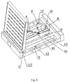
- one end of the panel 11 is rotatably arranged on the base 5 through a hinge 3, a surface of the panel 11 for covering the base 5 is provided with a plurality of floating plates 2, one end of the base 5 different from the end of the base 5 rotatably connected with the panel 11 (one end of the base 5 different from the end of the base 5 rotatably connected with the panel 11 refers to one end of the base 5 opposite to the end of the base 5 rotatably connected with the panel 11, i.e., one end of the base that is not rotatably connected with the panel 11) is provided with a first water inlet.
- the base 5 is provided with four water storage cavities. It should be noted that the embodiment of the present application has no limitation on the number of water storage cavities, and one or multiple water storage cavities can be provided. When multiple water storage cavities are disposed in parallel, the water storage cavities may be separated by beams 22, as shown in FIG. 2 .
- the first water inlet 10 may be disposed on the side surface of the base 5, as shown in FIG. 3 to FIG. 5 .
- water can enter the water storage cavity from the first water inlet 10; and when the amount of water is relatively large, water can enter the water storage cavity of the base 5 from the first water inlet 10 and an upper space of the base 5 adjacent to the side of the first water inlet 10, and the floating plates 2 can drive the panel 1 to rotate upward around the hinge 3 under the action of buoyancy of water.
- each automatic water retaining unit is provided with two connecting plates 9, the upper part of the connecting plate 9 is fixed (for example, welded) to the base 5, and in use, the connecting plates 9 are detachably mounted to the ground through fasteners 12 (for example, bolts), thereby fixing the automatic water retaining units.
- the width of each base unit and panel unit 11 is 200 mm to 1000 mm, and the transportability can be good.
- the base 5 is provided with through holes parallel to a rotating shaft of the panel 11, and the two adjacent bases 5 are detachably connected together through bolts disposed in the through holes.
- a connecting surface of each base 5 with the other base 5 is provided with connecting holes 113, and in some embodiments, the connecting holes 113 are bolt connecting holes.
- the two sides of the water retaining unit can be respectively provided with a buffer slope 17 detachably mounted on the ground through bolts.
- the inclination of the buffer slope 17 can be 5 degrees to 45 degrees.
- the buffer slope 17 adjacent to the side of the first water inlet 10 is provided with a second water inlet 30, and the first water inlet 10 is communicated with the second water inlet 30, as shown in FIG. 3 and FIG. 28 .
- the buffer slopes 17 may not be disposed on the two sides of the base 5, for example, when the height of the automatic water retaining device in the present application is less than four to five centimeters, the buffer slopes 17 may not be disposed.
- the two sides of the base 5 are not provided with the buffer slopes 17, and the structure of the other components is similar to that when the buffer slopes are disposed in FIG. 3 .
- the buffer slopes 17 and the base 5 may also be set as an integral mechanism, and are not provided with the second water inlet, but only provided with the first water inlet, and the first water inlet pass through the buffer slope on the side where the first water inlet is located.
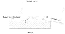
- one end of the base 5 rotatably connected with the panel 11 may be further provided with a drainage device, as shown in FIG. 6 to FIG. 9 .
- the drainage device can drain water accumulated in the water retaining device, thereby avoiding corroding the water retaining device. For example, after the water retaining device is mounted, especially mounted to a slope, when the panel is flattened, there will be water accumulated inside. The water accumulated inside can be drained through the drainage device, thereby avoiding corroding metal components in the device, such as metal bases.
- the drainage device comprises a first water outlet 20 disposed on the base 5.
- the drainage device may further comprise a drainage switch 21 disposed at the first water outlet 20 and linked with the panel 11; when the panel 11 covers the base 5, the drainage switch 21 is opened; and when the panel 11 rotates to open beyond a set angle, the drainage switch 21 is closed.
- the set angle can be 3 degrees to 15 degrees.
- the buffer slopes 17 and the base 5 are an integral mechanism, there is no second water outlet, but only the first water outlet, and the first water outlet passes through the buffer slope on the side where it is located.
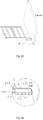
- the drainage switch device 21 comprises a baffle plate 211, a homocentric-square-shaped fixing plate 212, a movable door 213 and a switch spring 214, the fixing plate 212 is fixed to a position of the base 5 adjacent to the first water outlet 20, and a middle opening of the fixing plate 212 is communicated with the first water outlet 20; the movable door 213 is connected to the fixing plate 212 through a guide rod 215 over which the switch spring 214 is sleeved, one end of the switch spring 214 is fixed to the fixing plate 212, the movable door 213 and the switch spring 214 are sequentially sleeved over the guide rod 215 from outside to inside, and one end of the guide rod 215 away from the end fixed to the fixing plate 212 is fixed to one end of the switch spring 214 away from the movable door 213 through a pin (now shown); one side of the movable door 213 opposite to the switch spring is fixedly provided with an ejector rod 216, the eject
- the ejector rod 216 is provided with a thread
- the movable door 213 is provided with a threaded hole
- the ejector rod 216 is fixed to the movable door 213 through the thread; and in use, the ejector rod 216 can be manually screwed in and out of the threaded hole of the movable door 213 to adjust the opening of the movable door 213, thereby implementing the adjustment of the drainage capacity.
- the baffle plate 211 When the drainage switch 21 is used for flattening the panel 11, the baffle plate 211 abuts against the ejector rod 216 so as to drive the movable door 213 to compress the switch spring 214, the movable door 213 leaves the fixing plate 212, the first water outlet 20 is opened and is in the drainage state to discharge the residual water, thereby avoiding corroding the metal base; and when the panel 11 floats up, the switch spring 214 compresses the movable door 213, the movable door 213 is closely attached to the fixing plate 212, and the first water outlet 20 is closed to avoid water drainage.
- the ejector rod 216 is a flat-nosed screw, so that the baffle plate 211 has a larger contact area with the ejector rod, and the ejection effect is better.
- the drainage device can also prevent the water retaining device from prematurely blocking the inlet passage and affecting the passage of vehicles.
- the water inlet capacity of the first water inlet 10 is greater than the drainage capacity of the first water outlet 20.
- the switch spring 214 in the drainage switch 21 compresses the movable door 213, the movable door 213 is closely attached to the fixing plate 212, and the first water outlet 20 is closed to avoid drainage.
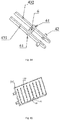
- the two adjacent panels 11 are connected through a sealing device formed by two hold-down strips 18 compacting one flexible sealing strip 19, each flexible sealing strip 19 is overlapped on the two adjacent panels 11, and the two hold-down strips 18 are respectively fixed to the two panels 11 through bolts and press the two sides of the flexible sealing strip 19, as shown in FIG. 10 .
- the flexible sealing strip 19 may be made of silicone rubber or a flexible metal sheet; and in some embodiments, the material of the flexible sealing strip 19 is in a two-layer structure, the bottom layer is 4mm-thick silicone rubber, and the surface layer is a 0.3mm stainless steel sheet.
- the panel 11 and the base 5 are sealed through a rear sealing device composed of two rear hold-down strips 181 and a rear flexible sealing strip 7, two sides of the rear flexible sealing strip 7 are respectively overlapped on the panel 11 and the base 5, the two rear hold-down strips 181 are respectively fixed to the panel 11 and the base 5 through bolts, and the two rear hold-down strips 181 respectively compact the two sides of the rear flexible sealing strip 7 to be attached to the panel 11 and the base 5, thereby implementing the sealing between the panel 11 and the base 5.
- the material for manufacturing the rear flexible sealing strip 7 is 4mm-thick silicone rubber, so the sealing effect is better and the service time is longer.
- second grooves 111 recessed toward the base 5 are respectively disposed on three edge positions of each panel 11 adjacent to the hinge 3, as shown in FIG. 11 , and the flexible sealing strip 19 and the rear flexible sealing strip 7 are disposed in the second grooves 111; and the hold-down strip 18 and one of the rear hold-down strips 181 are also fixed to the panel 11 through bolts, so that when the panel 11 covers the base 5, the tops of the hold-down strip 18 and the rear hold-down strip 181 are located on the same plane as the top of the panel.
- a gap 52 is disposed between the bottom of each beam 22 and the ground, the gap can well ensure that the beam 22 and the floating plates 2 do not contact the ground so that water can enter the bottom, and the water storage cavities are communicated with each other so as to generate uniform buoyancy on the panel 11.
- One end of each base 5 adjacent to the first water inlet 10 is provided with an oblique nail 53 for fixing the end of the base 5 to the ground, the oblique nail 53 is inclined toward the other end of the base 5 to prevent the base from turnover, and the number of oblique nails 53 on each base 5 may be one or multiple.
- the water storage cavity there are many ways for the water storage cavity to be communicated with the first water inlet 10, in addition to the above-mentioned way that the bottom of the beam 22 is provided with a gap and one of the water storage cavities is communicated with the first water inlet, it is also possible that the number of the first water inlets is set to be the same as the number of the water storage cavities, each water storage cavity is communicated with one first water inlet and the number of the first water inlets is the same as the number of the second water inlets.
- one end of the base 5 adjacent to the first water inlet 10 is provided with an elastic device 54 capable of contacting the panel, so that after the panel 11 covers the base, the panel 11 presses the spring and the spring generates an upward force, thereby facilitating the floating of the panel.
- the above elastic device 54 is a spring, and is disposed in a groove 421; and the spring is mounted in the groove 421 and produces a moderate elasticity within the retractable range, so that the panel and the base can not automatically bounce off in normal use.
- the number of the springs in the present application may also be two or more, and a proper number of springs can be set according to actual demands.
- each panel 11 is provided with a connecting device 4 which is respectively connected with the base 5 and used for pulling the panel 11 when the panel 11 floats up; and thus, the panel 11 can be supported when completely floating up, and can fall down only by manual intervention when not used for water retaining, thereby preventing the sudden closing from hurting people around.
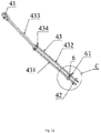
- each connecting device 4 comprises an upper fixing portion 41 disposed on the panel 11 and a lower fixing portion 42 disposed on the base 5, a connecting rod 43 is further disposed between the upper fixing portion 41 and the lower fixing portion 42, and the connecting rod 43 is foldable.
- the top of the beam 22 rotatably connected with the lower connecting rod is provided with a groove 421 disposed along the longitudinal direction of the beam, and the groove 421 constitutes the lower fixing portion 42;
- the connecting rod 43 comprises a left lower connecting rod 431, a right lower connecting rod 432, an upper connecting rod 433, a hinge 434, a left lower connecting rod 431, a right lower connecting rod 432 and an upper connecting rod 433 which are respectively rotatably connected through the hinge 434 and fold or unfold by using the hinge 434 as a pivot, and the left lower connecting rod 431 and the right lower connecting rod 432 are respectively located on two sides of the upper connecting rod 433; and the left lower connecting rod 431 and the right lower connecting rod 432 are respectively connected with the inside of the groove 421 rotatably disposed on the lower fixing portion 42 through an axis pin 42, a position between the left lower connecting rod 431 and the right lower connecting rod 432 adjacent to the base 5 is also connected with a transverse spring 6, one side of a position where the left
- the number of water storage cavities is one more than the number of the beams. If the number of the beams is multiple, one of the beams may be optionally provided with a groove 421 for rotatably connecting with the left lower connecting rod 431 and the right lower connecting rod 432.
- the cup-headed flange 61 on the outer sides of the left lower connecting rod 431 and the right lower connecting rod 432 expand outward under the action of the springs 6, the cup-headed flange 61 is exposed out of the groove 421 inside the beam, and the cup-headed flange 61 abuts against the top edge of the groove 421, thereby limiting the left lower connecting rod 431 and the right lower connecting rod 432 from rotating downward; thus, after water retreats, the floating plates 11 cannot cover down due to the dead weight, and it is necessary to manually push the panel 11 downward such that the cup-headed flange 61 can contract inward to enter the groove 421, and the left lower connecting rod 431 and the right lower connecting rod 432 rotate downward; and at this time, the upper connecting rod and the lower connecting rod are folded together and received in the groove 421, so that the panel 11 can be closed, thereby preventing the sudden closing of the panel 11 from hurting people around.
- the panel 11 in the present application comprises an upper panel 101 on the upper layer and a lower panel 102 on the lower layer, the lower panel 102 is rotatably disposed on the base through a hinge 3, the upper panel 101 is detachably mounted on the lower panel 102 through rivets, the floating plates 2 are fixed to the lower panel 102 and the lower panel 102 is also provided with a plurality of lightening holes 112, and the floating plates 2 and the lightening holes 112 are respectively located on the surface of the lower panel 102 covering the base.
- the panel 11 is made of aluminum, and is light in weight.
- the lightening holes 112 are filled with a buoyancy material (a material being light in weight, being more buoyant in water and floating on water) capable of generating buoyancy of water, and in some embodiments, the buoyancy material may be foam made of polyurethane.
- the upper surface of the upper panel 101 is also provided with concave grains 133 or convex grains, thereby enhancing a certain friction force for the passing vehicles, preventing the vehicles passing over the water retaining device from slipping in rainy or snowy weather, and having favorable antiskid effects.
- one side of the floating plate 2 facing the base 5 is also provided with a water level warning mark 15.
- the water level warning mark 15 is a scale display or a warning color display. When the panel 11 floats up, working personnel or other people around can be reminded to raise the water retaining device or properly drain the water. It can also play a better warning role for the entering vehicles.
- the floating plates 2 in the present application may be made of water-resistant foam, and thus, has longer service life.
- the two sides of the automatic water retaining device are wall surfaces
- the automatic water retaining device may further comprise flexible sealing plates respectively disposed between both sides of the automatic water retaining device and both side walls, wherein the flexible sealing plates are respectively fixedly connected to the side walls and the panel 11 of the automatic water retaining unit adjacent to the side walls in the automatic water retaining device, and after the panel 11 floats up, the flexible sealing plates are driven to bend therewith to implement a water retaining function between the two sides of the automatic water retaining device and the two side walls, thereby preventing the clearance leakage between the water retaining device and the side walls.
- a triangular flexible sealing plate 1 may be disposed between the automatic water retaining unit at the end of the automatic water retaining device and the wall 16, the flexible sealing plate 1 may be made of silicone rubber, the bottom side thereof is detachably mounted to the wall 16 through the sealing plate wall surface hold-down strip 161, and a waist side is detachably mounted to the panel 11 adjacent to the wall surface through a sealing plate panel hold-down strip 162, thereby implementing the favorable sealing effect between the panels 11 on the two ends and the wall 16.
- the sealing plate wall surface hold-down strip 161 on the wall 16 and the base form a 45-degree angle, and the bottom end of the sealing plate wall surface hold-down strip 161 is close to the end of the outermost rear hold-down strip 181; the sealing plate wall surface hold-down strip 161, the wall surface anti-leakage flexible sealing plate 1, the sealing plate panel hold-down strip 162 and the panel 11 form a complete wall surface anti-leakage flexible sealing cavity; and after the panel 11 floats up, the flexible sealing plate 1 is driven to bend therewith, thereby avoiding affecting the anti-leakage sealing effect of the wall surface.
- the flexible sealing plate 1 is in a shape of a right-angled triangle, one leg of the right-angle triangle is fixed to an upper edge of the panel, and the hypotenuse is fixed to the wall surface 16.
- a right-angled trapezoidal flexible sealing plate 13 may be disposed between the automatic water retaining unit at the end of the automatic water retaining device and the wall 16, as shown in FIG. 21 to FIG.
- the water retaining device of the present embodiment further comprises two right-angled trapezoidal flexible sealing plates 13 respectively disposed on two sides of the water retaining device, the beveled sides of the sealing plates 13 are fixedly connected to the side wall, a right-angle side is fixedly connected to one end of the panel 11 adjacent to the side wall, and the top side is flush with the rear edge of the base 5 and is hermetically connected with the ground.
- the water retaining device further comprises a wall surface hold-down strip 161 and a panel hold-down strip 162, the base angle of the beveled side of the sealing plate 13 is 45 degrees, the wall surface hold-down strip 161 fixes the beveled side of the sealing plate 13 to the side wall 16 along the side wall surface by 45 degrees, and the panel hold-down strip 162 is parallel to the side wall surface and fixes the right-angle side of the sealing plate 13 to the upper surface of the panel 11.
- the sealing plate 13 is a flexible material, and can be cut by a constructor on a construction site to adjust the width of the top side, so that the width of the top side of the sealing plate 13 is equal to the sum of the distance between the outermost side of the base and the side wall and the width of the panel hold-down strip, thereby greatly facilitating the site mounting construction and enhancing the adaptability of the product.
- the number of the water retaining units is not less than two, and the panels 11 fixedly connected to the right-angle sides of the sealing plates 13 are panels of the two water retaining units of the water retaining device respectively adjacent to the two side walls.
- the two ends of the unit are hermetically connected with the two side walls through the sealing plates 13.
- the outer sides of the panels of the two water retaining units respectively adjacent to the two side walls are hermetically connected with the two side walls through the sealing plates 13.
- a gap filler 6 having the same height as the base 5 is further disposed between the base 5 adjacent to the side wall 16 and the side wall, as shown in FIG. 24 .
- One end of the gap filler 6 abuts against the side wall 16, the other end is hermetically fixedly connected to the base 5, the lower surface is hermetically fixedly connected to the ground, and the top side of the sealing plate 13 is disposed on the upper surface of the gap filler 6 and fixes the top side of the sealing plate 13 to the gap filler 6 through a gap filler hold-down strip 163.
- the gap between the base 5 and the side wall 16 is filled with the gap filler 6, and the gap between the panel 11 and the side wall 16 is filled with the sealing plate 13, thereby ensuring the completeness and effectiveness of the whole water retaining scheme, lowering the construction difficulty of the top side of the sealing plate 13 and prolonging the service life of the sealing plate 13. Since the sealing plate 13 is the most vulnerable part in the whole water retaining device, the prolonging of the service life of the sealing plate 13 can prolong the service life of the whole water retaining device.
- the gap filler 6 is a strip having a Z-shaped cross section, the length thereof is greater than the distance between the outermost side of the base 5 and the side wall 16, a gap filler wall surface fixing plate 64 on the top end is fixed to the side wall 16, a gap filler upper surface 61 on the other end is attached to an upper surface 151 of the rear edge of the base 5, a gap filler middle vertical surface 62 is attached to a rear end surface 152 of the rear edge of the base, and a lower surface 63 of the gap filler 6 is attached to the ground.
- the inner vertical height thereof is the same as the height of the rear edge of the base 5, thereby ensuring the sealing of the lower gap between the base 5 and the side wall 16, and the upper gap is sealed by the sealing plate 13.
- FIG. 24 is a structure schematic view when the gap filler is a Z-shaped strip, in which a fixing plate 64 with the wall surface 16 is added.
- FIG. 25 is a mounting schematic view when the gap filler is a Z-shaped strip, in which the panel 11 and the front and rear slopes 7 of the base are not shown.
- FIG. 26 is a mounting schematic partial enlarged view when the gap filler is a Z-shaped strip in FIG. 25 , in which the panel and the front and rear slopes 17 of the base are not shown.
- the length of the strip having a Z-shaped cross section may be the distance between the outermost side of the base 5 and the side wall plus 5 centimeters. Therefore, when mounting on side, the gap filler 6 of the strip having a Z-shaped cross section can satisfy the gap filling length between the outermost side of the base 5 and the side wall 16 without cutting, thereby ensuring the sealability and facilitating construction.
- the gap filler 6 may be a square tube having one end against the side wall 16 and the other end against the side of the base 5, and the square tube has the same height as the base 5.
- the acting range of the gap filler can be quickly adjusted by a constructor on the construction site according to the distance between the base and the side wall, thereby ensuring the sealability and facilitating construction.
- the width of the top side of the sealing plate 13 is not less than the sum of the distance between the outermost side of the base 5 and the side wall and the width of the panel hold-down strip 162.
- the sealing plate 13 can be cut by a constructor on the construction side to adjust the width of the top side, so that the width of the top side of the sealing plate 13 mounted to the proper position is equal to the sum of the distance between the outermost side of the base and the side wall and the width of the panel hold-down strip. Therefore, the overall width of the water retaining device does not need to be strictly matched to the distance between the two side walls, and the overall width of the water retaining device can be adjusted within a wide range, thereby facilitating the prior measurement and on-site mounting construction.
- the automatic water retaining device may further comprise a bulge 24 for limiting the floating angle of the panel 11, and the bulge 24 is disposed on the wall surface 16 on two sides of the automatic water retaining device.
- the automatic water retaining device may further comprise a fixing rod 23 for preventing the base from turnover, wherein the fixing rod 23 is fixed to the wall surfaces on the two sides of the automatic water retaining device, and the bottom end thereof is fixed with one end of the outermost base with the first water inlet.
- a base anti-leakage flexible sealing strip 50 is disposed between the base 5 and the ground, the base anti-leakage flexible sealing strip 50 is deposed on one end of the base different from the first water inlet 10 (i.e., one end of the base away from the first water inlet 10), one end of the base anti-leakage flexible sealing strip 50 is detachably mounted to the base through the sealing strip hold-down strip 501, and the other end is detachably mounted to the ground through the sealing strip hold-down strip 501.
- the base anti-leakage water flexible sealing strip 50 in the present application is not limited to the above mounting manner, and may also be disposed horizontally, wherein one end is mounted to the bottom of the base, and the other end is mounted to the ground, as shown in FIG. 28 .
- the base of the water retaining device may be disposed as low as possible to reduce the height of the whole device.
- the front end of the panel 11 is triggered to open upward along the hinge 3 to enter the water retaining state, and meanwhile, the normal passage of the vehicles is also stopped.
- the height of the lower edge of the first water inlet 10 from the ground can be raised.
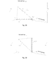
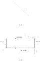
- the distance between the lower edge of the first water inlet 10 and the ground may be [3, 6] centimeters, for example, 4.5 centimeters, as shown in FIG. 29 .
- the first water inlet may be set as a grid structure and disposed on the upper surface of the base 5.
- the first water inlet may be set as a grid structure disposed on the upper surface of the base 5.
- the water can flow over the base 5 and enter the water storage cavity through the first water inlet 51 to open the panel 11, thereby performing the function that the panel 11 can be opened upward only when the water quantity at the front end of the base 5 reaches the water retaining threshold.
- the water retaining threshold at this time is the water level having an equal height as the base 5.
- the water retaining threshold depends on the drainage capacity of each application scenario and can be determined according to field experiments.
- the water retaining plate formed by the panel 11 is in the closed state, so that the vehicles can pass normally. Only when the water quantity at the inlet is large and the depth of the accumulated water is large, the front end of the panel 11 is opened upward along the hinge 3 to sufficiently block the water out of a garage.
- the water inlet grid can ensure the opening sensitivity of the device by increasing the water inlet amount, and can also ensure the structural strength, thereby preventing the device from being crushed by the vehicles.
- the time for opening the panel 11 can be further delayed to facilitate the passage of vehicles.
Landscapes
- Engineering & Computer Science (AREA)
- Structural Engineering (AREA)
- Architecture (AREA)
- General Engineering & Computer Science (AREA)
- Civil Engineering (AREA)
- Environmental & Geological Engineering (AREA)
- Ocean & Marine Engineering (AREA)
- Mechanical Engineering (AREA)
- Business, Economics & Management (AREA)
- Emergency Management (AREA)
- Special Wing (AREA)
- Buildings Adapted To Withstand Abnormal External Influences (AREA)
- Sewage (AREA)
Claims (18)
- Automatische Wasserrückhaltevorrichtung zum Sperren des Durchfließen von Wasser auf dem Boden zwischen zwei Seitenwänden, umfassend zwei oder mehr parallel angeordnete automatische Wasserrückhalteeinheiten, die automatische Wasserrückhalteeinheit umfasst eine Platte (11) und ein Unterteil (5), wobei das Unterteil (5) mit einem Wasserspeicherhohlraum versehen ist, die Platte (11) drehbar auf dem Unterteil (5) angeordnet ist, der Wasserspeicherhohlraum durch das Drehen der Platte (11) geöffnet und geschlossen wird, eine Oberfläche der Platte (11) zum Abdecken des Unterteils (5) mit einer schwimmenden Platte (2) versehen ist, ein Ende des Unterteils (5), das von dem mit der Platte (11) verbundenen Ende des Unterteils (5), verschieden ist, mit einem ersten Wassereinlass (10, 51) versehen ist, der mit dem Wasserspeicherhohlraum in Verbindung steht, und, wenn Wasser vom ersten Einlass (10, 51) in den Wasserspeicherhohlraum tritt und mit der schwimmenden Platte (2) in Kontakt kommt, Auftrieb an der schwimmenden Platte (2) erzeugt wird und die schwimmende Platte (2) die Platte (11) unter der Wirkung des Auftriebs zum Drehen und Öffnen treibt, wodurch eine Wasserrückhaltefunktion eingerichtet wird, dadurch gekennzeichnet, dass ein Ende des Unterteils (5), das mit der Platte (11) verbunden ist, mit einer Drainagevorrichtung versehen ist, die Drainagevorrichtung einen ersten Wasserauslass (20), der am Unterteil (5) angeordnet ist und mit dem Wasserspeicherhohlraum in Verbindung steht, und einen Drainageschalter (21) umfasst, der am ersten Wasserauslass (20) angeordnet und mit der Platte (11) verbunden ist, und wenn die Platte (11) das Unterteil (5) bedeckt, der Drainageschalter (21) geöffnet ist; und, wenn sich die Platte (11) dreht, um sich über einen festgelegten Winkel hinaus zu öffnen, der Drainageschalter (21) geschlossen ist, und wobei der Drainageschalter (21) eine bewegliche Tür (213), einen Führungsstab (215), eine Schalterfeder (214) und eine Prallplatte (211) umfasst, die an der Platte (11) befestigt ist, ein Ende des Führungsstabs (215) am Unterteils (5) befestigt ist, die Schalterfeder (214) und die bewegliche Tür (213) über den Führungsstab (215) geschoben sind, ein Ende des Führungsstabs (215), der von dem fest mit dem Unterteil (5) verbundenen Ende entfernt ist, an der Schalterfeder (214) befestigt ist, eine Seite der beweglichen Tür (213), die der Schalterfeder (214) entgegengesetzt ist, fest mit einem Auswerferstab (216) versehen ist, und die Prallplatte (211) den Auswerferstab (216) drückt, wenn sich die Platte (11) dreht, sodass die bewegliche Tür (213) entlang dem Führungsstab (215) vor und zurück gleitet, um den ersten Wasserauslass (20) zu öffnen und zu schließen.
- Automatische Wasserrückhaltevorrichtung nach Anspruch 1, dadurch gekennzeichnet, dass die Wassereinlasskapazität des ersten Wassereinlasses (10, 51) größer als die Drainagekapazität des ersten Wasserauslasses (20) ist.
- Automatische Wasserrückhaltevorrichtung nach Anspruch 1, dadurch gekennzeichnet, dass das Unterteil (5) fest im Boden verankert ist, und die automatische Wasserrückhaltevorrichtung ferner Pufferschrägen (17) umfasst, die auf beiden Seiten des Unterteils (5) angeordnet sind.
- Automatische Wasserrückhaltevorrichtung nach Anspruch 3, dadurch gekennzeichnet, dass die an die Seite des ersten Wasserauslasses (20) angrenzende Pufferschräge (17) mit einem zweiten Wasserauslass (31) versehen ist, der mit dem ersten Wasserauslass (20) in Verbindung steht.
- Automatische Wasserrückhaltevorrichtung nach Anspruch 1, dadurch gekennzeichnet, dass der erste Wassereinlass (51) eine Gitterstruktur aufweist und auf einer oberen Oberfläche des Unterteils (5) angeordnet ist.
- Automatische Wasserrückhaltevorrichtung nach Anspruch 1, dadurch gekennzeichnet, dass der Abstand zwischen der Unterkante des ersten Wassereinlasses (10) und dem Boden [3, 6] Zentimeter beträgt.
- Automatische Wasserrückhaltevorrichtung nach Anspruch 1, dadurch gekennzeichnet, dass sie ferner umfasst: flexible Abdichtplatten (1, 13), die jeweils zwischen beiden Seiten der automatischen Wasserrückhaltevorrichtung und beiden Seitenwänden angeordnet sind, wobei die flexiblen Abdichtplatten (1, 13) jeweils fest mit den Seitenwänden und der Platte (11) der automatischen Wasserrückhalteeinheit verbunden sind, die an die Seitenwand in der automatischen Wasserrückhaltevorrichtung angrenzt, und die flexiblen Abdichtplatten (1, 13), nachdem die Platte (11) nach oben schwimmt, zum Biegen mit derselben getrieben werden, um ein Wasserrückhalten zwischen den beiden Seiten der automatischen Wasserrückhaltevorrichtung und den beiden Seitenwänden einzurichten.
- Automatische Wasserrückhaltevorrichtung nach Anspruch 7, dadurch gekennzeichnet, dass die flexible Abdichtplatte (13) eine rechtwinklige trapezförmige Struktur aufweist, die abgeschrägte Seite der Abdichtplatte (13) fest mit der Seitenwand verbunden ist, die rechtwinklige Seite fest mit einem Ende der Platte (11) verbunden ist, die an die Seitenwand in der Wasserrückhalteeinheit angrenzt, die an die Seitenwand angrenzt, und die Oberseite mit der Hinterkante des Unterteils (5) bündig ist.
- Automatische Wasserrückhaltevorrichtung nach Anspruch 8, dadurch gekennzeichnet, dass sie ferner umfasst: Spaltfüller (6), der jeweils zwischen den beiden Seitenwänden und dem Unterteil (5) angrenzend an die beiden Seitenwände angeordnet ist, wobei der Spaltfüller (6) die gleiche Höhe wie das Unterteil (5) aufweist, ein Ende gegen die Seitenwand stößt, das andere Ende hermetisch fest mit dem Unterteil (5) verbunden ist, die Unterfläche hermetisch fest mit dem Boden verbunden ist, und die Oberseite der Abdichtplatte (13) auf der oberen Oberfläche des Spaltfüllers (6) angeordnet und fest mit dem Spaltenfüller (6) verbunden ist.
- Automatische Wasserrückhaltevorrichtung nach Anspruch 7, dadurch gekennzeichnet, dass sie ferner umfasst:
einen Wandoberflächen-Fixierstreifen (161), einen Platten-Fixierstreifen (162) und einen Spaltfüller-Fixierstreifen (163), wobei der Unterteilwinkel der abgeschrägten Seite der Abdichtplatte (13) 45 Grad beträgt, der Wandoberflächen-Fixierstreifen (161) die abgeschrägte Seite der Abdichtplatte (13) an der Seitenwand mit 45 Grad entlang der Seitenwandoberfläche befestigt, der Platten-Fixierstreifen (162) parallel zur Seitenwandoberfläche verläuft, die rechtwinklige Seite der Abdichtplatte (13) auf der oberen Oberfläche der Platte (11) befestigt ist, der Spaltfüller-Fixierstreifen (163) die Oberseite der Abdichtplatte (13) an der oberen Oberfläche des Spaltfüllers (6) befestigt. - Automatische Wasserrückhaltevorrichtung nach Anspruch 10, dadurch gekennzeichnet, dass Breite der Oberseite der Abdichtplatte nicht kleiner als die Summe des Abstands zwischen der äußersten Seite des Unterteils (5) und der Seitenwand und der Breite des Platten-Fixierstreifens (162) ist.
- Automatische Wasserrückhaltevorrichtung nach Anspruch 7, dadurch gekennzeichnet, dass die flexible Abdichtplatte (1) eine dreieckige Struktur aufweist, die Unterseite derselben fest mit einem Ende der Platte (11) verbunden ist, die an die Seitenwand in der automatischen Wasserrückhalteeinheit angrenzt, die an die Seitenwand angrenzt, und eine Taillenseite fest mit der Seitenwand verbunden ist.
- Automatische Wasserrückhaltevorrichtung nach Anspruch 1, dadurch gekennzeichnet, dass das Unterteil (5) mit zwei oder mehr parallelen Wasserspeicherhohlräumen versehen ist und die Vorrichtung ferner umfasst:einen Balken (22) zum Trennen der Wasserspeicherhohlräume;einen oberen Verbindungsstab (433), von dem ein Ende drehbar mit der Platte (11) verbunden ist; undeinen unteren Verbindungsstab, von dem ein Ende drehbar mit dem Balken (22) am Unterteil (5) verbunden ist, wobei das andere Ende des oberen Verbindungsstabs (433) gelenkig mit dem anderen Ende des unteren Verbindungsstabs verbunden ist.
- Automatische Wasserrückhaltevorrichtung nach Anspruch 13, dadurch gekennzeichnet, dass die Oberseite des Balkens (22), der drehbar mit dem unteren Verbindungsstab verbunden ist, in Längsrichtung mit einer Rille (421) versehen ist, um den oberen Verbindungsstab (433) und den unteren Verbindungsstab unterzubringen, der untere Verbindungsstab einen linken unteren Verbindungsstab (431) und einen rechten unteren Verbindungsstab (432) umfasst, die sich jeweils auf zwei Seiten des oberen Verbindungstabs (433) befinden, ein Ende von jedem der beiden gelenkig mit dem oberen Verbindungstab (433) verbunden ist, und das andere Ende von jedem der beiden drehbar mit den Innenwänden der beiden Seiten der Rille (421) verbunden ist.
- Automatische Wasserrückhaltevorrichtung nach Anspruch 1, dadurch gekennzeichnet, dass sie ferner umfasst eine elastische Vorrichtung (54), die an einem Ende des Unterteils (5), das an den ersten Wassereinlass (10, 51) angrenzt, angeordnet und dazu in der Lage ist, mit der Platte (11) in Kontakt zu kommen, wobei die Platte (11) gegen die elastische Vorrichtung (54) drückt, wenn sich die Platte (11) im geschlossenen Zustand befindet.
- Automatische Wasserrückhaltevorrichtung nach Anspruch 1, dadurch gekennzeichnet, dass sie ferner einen Befestigungsstab (23) umfasst, um zu verhindern, dass das Unterteil umkippt, wobei der Befestigungsstab (23) an den beiden Seitenwänden der automatischen Wasserrückhaltevorrichtung befestigt ist und das Unterende desselben an einem Ende des Unterteils (5) der automatischen Wasserrückhalteeinheit befestigt ist, die an die Seitenwand mit dem ersten Wassereinlass (10, 51) angrenzt.
- Automatische Wasserrückhaltevorrichtung nach Anspruch 1, dadurch gekennzeichnet, dass die Platte (11) eine obere Platte (101) auf der oberen Schicht und einer unteren Platte (102) auf der unteren Schicht umfasst, wobei die untere Platte (102) drehbar auf dem Unterteil (5) angeordnet ist, die obere Platte (101) lösbar an der unteren Platte (102) befestigt ist, und die schwimmende Platte (2) an der unteren Platte (102) befestigt ist.
- Automatische Wasserrückhaltevorrichtung nach Anspruch 1, dadurch gekennzeichnet, dass die Oberfläche der Platte (11), die den Wasserspeicherhohlraum abdeckt, ferner mit einem Erleichterungsloch (112) vorgesehen ist, und das Erleichterungsloch (112) mit einem Auftriebsmaterial gefüllt ist.
Applications Claiming Priority (4)
| Application Number | Priority Date | Filing Date | Title |
|---|---|---|---|
| CN201610078353.2A CN105545190B (zh) | 2015-10-31 | 2016-02-04 | 模块化自动挡水装置 |
| CN201610980464.2A CN106437462B (zh) | 2016-11-08 | 2016-11-08 | 地下车库延时挡水装置 |
| CN201610996954.1A CN106400741B (zh) | 2016-11-14 | 2016-11-14 | 一种挡水装置 |
| PCT/CN2017/072874 WO2017133680A1 (zh) | 2016-02-04 | 2017-02-04 | 自动挡水装置 |
Publications (3)
| Publication Number | Publication Date |
|---|---|
| EP3401492A1 EP3401492A1 (de) | 2018-11-14 |
| EP3401492A4 EP3401492A4 (de) | 2019-01-09 |
| EP3401492B1 true EP3401492B1 (de) | 2019-10-23 |
Family
ID=59500091
Family Applications (1)
| Application Number | Title | Priority Date | Filing Date |
|---|---|---|---|
| EP17747000.2A Active EP3401492B1 (de) | 2016-02-04 | 2017-02-04 | Automatische wassersperrvorrichtung |
Country Status (8)
| Country | Link |
|---|---|
| US (1) | US10422095B2 (de) |
| EP (1) | EP3401492B1 (de) |
| JP (1) | JP6666472B2 (de) |
| KR (1) | KR102126952B1 (de) |
| AU (1) | AU2017215797B2 (de) |
| CA (1) | CA3013517C (de) |
| GB (1) | GB2561798B8 (de) |
| WO (1) | WO2017133680A1 (de) |
Families Citing this family (27)
| Publication number | Priority date | Publication date | Assignee | Title |
|---|---|---|---|---|
| CN107975282B (zh) * | 2017-12-06 | 2023-05-30 | 贵州工程应用技术学院 | 一种汽车防水淹装置 |
| GB2569370A (en) * | 2017-12-15 | 2019-06-19 | Haawal Eng As | Portable water barrier |
| US10619318B1 (en) * | 2019-05-24 | 2020-04-14 | Floodbreak, L.L.C. | Flood barrier |
| CN111139833A (zh) * | 2020-01-31 | 2020-05-12 | 魏嘉轩 | 一种水利防洪墙修建设备 |
| CN112095545A (zh) * | 2020-08-25 | 2020-12-18 | 童宗明 | 一种基于非牛顿流体的缓冲防护型防汛板 |
| CN112049214B (zh) * | 2020-09-14 | 2021-12-17 | 淮北市荣恋科技有限公司 | 地下车库进口泄水结构 |
| CN112647750A (zh) * | 2020-12-24 | 2021-04-13 | 南京信息职业技术学院 | 一种拼接水池及使用方法 |
| CN112982284B (zh) * | 2021-02-25 | 2023-02-10 | 青岛理工大学 | 一种地下车库水动力阻水装置及方法 |
| CN113071608B (zh) * | 2021-04-01 | 2022-05-10 | 山东韵丰环保科技有限公司 | 一种自动定时浮标检测装置 |
| JP7354177B2 (ja) * | 2021-04-07 | 2023-10-02 | 古河電気工業株式会社 | 止水装置 |
| CN113175065B (zh) * | 2021-04-17 | 2022-03-08 | 江阴澄云达建设工程有限公司 | 地下车库雨水分区排水系统 |
| CN113585172B (zh) * | 2021-08-11 | 2022-10-11 | 南京市水利规划设计院股份有限公司 | 一种市政用地铁口挡水坝 |
| CN113512917A (zh) * | 2021-08-13 | 2021-10-19 | 吴天伦 | 一种地下设施防进水装置及使用方法 |
| CN113802520A (zh) * | 2021-09-18 | 2021-12-17 | 安徽科技学院 | 一种用于地下设施入口处的自动截水装置 |
| CN113775285B (zh) * | 2021-09-27 | 2025-04-18 | 浙江绿城利普建筑设计有限公司 | 一种地下出入口多级挡水板结构及其使用方法 |
| JP7444828B2 (ja) * | 2021-09-28 | 2024-03-06 | 古河電気工業株式会社 | 止水装置、止水構造 |
| JP7444829B2 (ja) * | 2021-09-28 | 2024-03-06 | 古河電気工業株式会社 | 止水装置、止水構造 |
| CN114108553A (zh) * | 2021-12-06 | 2022-03-01 | 周立武 | 一种水利工程用防洪堤 |
| CN114481949B (zh) * | 2022-02-26 | 2023-06-13 | 中国长江电力股份有限公司 | 防止水电站泄洪道检修时渗水的挡排水系统及方法 |
| CN114775641B (zh) * | 2022-05-30 | 2023-08-29 | 南京旭浦建材科技有限公司 | 一种预制密肋空腔墙板 |
| CN115354953B (zh) * | 2022-09-08 | 2024-03-19 | 安阳建工(集团)有限责任公司 | 一种翻转式钢筋混凝土挡水墙构造 |
| CN115807439B (zh) * | 2022-12-28 | 2023-08-22 | 连云港市金河水利工程建设监理有限公司 | 一种水利工程施工止水装置 |
| CN116927122B (zh) * | 2023-07-27 | 2025-12-02 | 湖南汉坤实业有限公司 | 一种便于排水的水马围挡 |
| CN116770769B (zh) * | 2023-08-01 | 2024-01-09 | 威海水利工程集团有限公司 | 一种地埋翻板式止水闸门 |
| CN116988425B (zh) * | 2023-08-09 | 2024-07-23 | 周口市水利勘测设计院 | 一种水利工程施工用挡水装置 |
| CN118360901B (zh) * | 2024-06-19 | 2024-08-30 | 山东省煤田地质局第一勘探队 | 一种海岸带泥沙侵蚀防护结构 |
| CN118757068B (zh) * | 2024-09-05 | 2024-12-17 | 中铁建工集团第二建设有限公司 | 一种地下车库挡水结构 |
Family Cites Families (24)
| Publication number | Priority date | Publication date | Assignee | Title |
|---|---|---|---|---|
| JPS5951826U (ja) * | 1982-09-27 | 1984-04-05 | 株式会社栗本鉄工所 | 転倒ゲ−トの水密保持装置 |
| DE19509970C2 (de) * | 1995-03-18 | 1997-06-05 | Herbert Riedmayer | Klappe zum Absperren eines oben offenen Gerinnes |
| JP3605739B2 (ja) * | 1995-11-15 | 2004-12-22 | 豊国工業株式会社 | 防水扉の起立装置 |
| DE10162568A1 (de) * | 2001-12-19 | 2003-07-17 | Seidl & Partner Gmbh Gesamtpla | Bauwerksegment für ein Hochwasserschutzbauwerk, Bauwerk und Verfahren zur Errichtung des Bauwerks |
| JP2003227125A (ja) * | 2002-02-04 | 2003-08-15 | Hitachi Zosen Corp | 起伏ゲート |
| JP2003253912A (ja) * | 2002-03-01 | 2003-09-10 | Kumagai Gumi Co Ltd | 水位追従式起伏ゲート装置 |
| US6623209B1 (en) * | 2002-04-04 | 2003-09-23 | Floodbreak Llc | Automatic flood gate |
| JP2005344486A (ja) * | 2004-05-31 | 2005-12-15 | Koichi Mochizuki | 起伏ゲート装置 |
| GB2465005B (en) * | 2008-11-04 | 2012-04-11 | John Charles Macintosh Forrest | An apparatus and method for flood defence |
| CN201448029U (zh) * | 2009-08-04 | 2010-05-05 | 陈铭铸 | 一种防汛挡水装置 |
| US8246272B1 (en) * | 2010-01-19 | 2012-08-21 | Denios, Inc. | Actuated spill barrier |
| US20120034032A1 (en) * | 2010-08-05 | 2012-02-09 | Waters Jr Louis A | Self-Actuating Flood Guard |
| US8511939B2 (en) * | 2010-12-27 | 2013-08-20 | Floodbreak, L.L.C. | Self-actuating storm surge barrier |
| JP5845025B2 (ja) * | 2011-08-24 | 2016-01-20 | 日立造船株式会社 | 浮体式フラップゲートの扉体構造 |
| KR101115582B1 (ko) * | 2011-11-04 | 2012-02-22 | 주식회사 이건 | 자동개폐가 가능한 가동보 |
| KR200467597Y1 (ko) * | 2013-04-19 | 2013-06-21 | 권대운 | 자석을 이용하여 신속설치가 가능한 우수유입 방지 물막이 장치 |
| CN103306247B (zh) * | 2013-06-09 | 2015-10-14 | 王辉 | 水利景观活动挡水坝 |
| JP6176534B2 (ja) * | 2014-02-24 | 2017-08-09 | 株式会社 ▲高▼▲橋▼監理 | 洪水用止水装置 |
| GB2514879B (en) * | 2014-03-06 | 2015-05-06 | Antonios Toumazis | Self-operated barrier for flood, spill and other protection |
| CN104120907A (zh) * | 2014-08-13 | 2014-10-29 | 南京军理智能科技股份有限公司 | 一种自动挡水装置 |
| CN204456011U (zh) * | 2015-01-09 | 2015-07-08 | 上海市水利工程设计研究院有限公司 | 自浮式上翻闸门挡水装置 |
| CN105133552A (zh) * | 2015-08-24 | 2015-12-09 | 湖南力威液压设备有限公司 | 平衡式液压拦河坝 |
| CN105545190B (zh) * | 2015-10-31 | 2017-02-22 | 南京军理科技股份有限公司 | 模块化自动挡水装置 |
| CN205387898U (zh) * | 2015-10-31 | 2016-07-20 | 南京军理科技股份有限公司 | 模块化自动挡水装置 |
-
2017
- 2017-02-04 AU AU2017215797A patent/AU2017215797B2/en active Active
- 2017-02-04 EP EP17747000.2A patent/EP3401492B1/de active Active
- 2017-02-04 CA CA3013517A patent/CA3013517C/en active Active
- 2017-02-04 WO PCT/CN2017/072874 patent/WO2017133680A1/zh not_active Ceased
- 2017-02-04 KR KR1020187022866A patent/KR102126952B1/ko active Active
- 2017-02-04 US US16/073,530 patent/US10422095B2/en active Active
- 2017-02-04 JP JP2018560706A patent/JP6666472B2/ja active Active
- 2017-02-04 GB GB1812923.9A patent/GB2561798B8/en active Active
Non-Patent Citations (1)
| Title |
|---|
| None * |
Also Published As
| Publication number | Publication date |
|---|---|
| JP2019504954A (ja) | 2019-02-21 |
| US10422095B2 (en) | 2019-09-24 |
| EP3401492A1 (de) | 2018-11-14 |
| KR20180100657A (ko) | 2018-09-11 |
| CA3013517C (en) | 2019-12-03 |
| WO2017133680A1 (zh) | 2017-08-10 |
| JP6666472B2 (ja) | 2020-03-13 |
| KR102126952B1 (ko) | 2020-06-26 |
| US20190032293A1 (en) | 2019-01-31 |
| GB2561798B8 (en) | 2019-07-24 |
| AU2017215797A1 (en) | 2018-08-16 |
| EP3401492A4 (de) | 2019-01-09 |
| GB201812923D0 (en) | 2018-09-19 |
| AU2017215797B2 (en) | 2019-07-11 |
| GB2561798A8 (en) | 2018-10-31 |
| GB2561798B (en) | 2019-06-26 |
| CA3013517A1 (en) | 2017-08-10 |
| GB2561798A (en) | 2018-10-24 |
Similar Documents
| Publication | Publication Date | Title |
|---|---|---|
| US10422095B2 (en) | Automatic water barrier device | |
| EP3105376B1 (de) | Selbstaktivierende hochwasserschutzbarriere | |
| CN105545190B (zh) | 模块化自动挡水装置 | |
| US20030190193A1 (en) | Automatic flood gate | |
| EP2915923A1 (de) | Selbstbetriebene barriere für flut, ausläufe und anderen schutz | |
| CN107476247B (zh) | 滑轮牵引的埋入式防洪墙 | |
| CN211819117U (zh) | 一种用于作战洞库口部具有伪装功能的防洪装置 | |
| CN205387898U (zh) | 模块化自动挡水装置 | |
| CN107620288B (zh) | 百叶式防洪墙 | |
| KR20160013364A (ko) | 인양식 수문장치 | |
| CN116163265B (zh) | 一种隐藏式防洪墙用的升降排水一体化装置 | |
| CN107476248B (zh) | 浮球摆杆驱动的埋入式防洪墙 | |
| CN115075187B (zh) | 一种模块化地库入口挡水系统 | |
| CN105672212B (zh) | 免电力掀起式防洪闸门 | |
| CN115807406A (zh) | 一种具有自应急感应功能的小型城市防汛墙 | |
| CN216156488U (zh) | 一种城市地库水力防洪闸 | |
| GB2371324A (en) | Pivotable flood barrier | |
| CN223593289U (zh) | 一种具有侧装式密封条的防洪闸 | |
| CN211228275U (zh) | 一种高速公路防护栏缓冲装置 | |
| CN120425676A (zh) | 一种具有侧装式密封条的防洪闸 | |
| CN218711921U (zh) | 一种道路路面用排水装置 | |
| CN111364820A (zh) | 一种设于汽车停车位的阻水保护装置 | |
| CN218150702U (zh) | 一种智能多防型平移门 | |
| KR102599629B1 (ko) | 지하 출입구 차수 장치 | |
| ES1268886U (es) | Dispositivo anti inundaciones |
Legal Events
| Date | Code | Title | Description |
|---|---|---|---|
| STAA | Information on the status of an ep patent application or granted ep patent |
Free format text: STATUS: THE INTERNATIONAL PUBLICATION HAS BEEN MADE |
|
| PUAI | Public reference made under article 153(3) epc to a published international application that has entered the european phase |
Free format text: ORIGINAL CODE: 0009012 |
|
| STAA | Information on the status of an ep patent application or granted ep patent |
Free format text: STATUS: REQUEST FOR EXAMINATION WAS MADE |
|
| 17P | Request for examination filed |
Effective date: 20180809 |
|
| AK | Designated contracting states |
Kind code of ref document: A1 Designated state(s): AL AT BE BG CH CY CZ DE DK EE ES FI FR GB GR HR HU IE IS IT LI LT LU LV MC MK MT NL NO PL PT RO RS SE SI SK SM TR |
|
| AX | Request for extension of the european patent |
Extension state: BA ME |
|
| A4 | Supplementary search report drawn up and despatched |
Effective date: 20181206 |
|
| RIC1 | Information provided on ipc code assigned before grant |
Ipc: E02B 3/10 20060101ALI20181130BHEP Ipc: E06B 9/00 20060101AFI20181130BHEP Ipc: E04H 6/42 20060101ALI20181130BHEP |
|
| DAV | Request for validation of the european patent (deleted) | ||
| DAX | Request for extension of the european patent (deleted) | ||
| RAP1 | Party data changed (applicant data changed or rights of an application transferred) |
Owner name: NANJING JUNLI TECH. CO. LTD. |
|
| GRAP | Despatch of communication of intention to grant a patent |
Free format text: ORIGINAL CODE: EPIDOSNIGR1 |
|
| STAA | Information on the status of an ep patent application or granted ep patent |
Free format text: STATUS: GRANT OF PATENT IS INTENDED |
|
| INTG | Intention to grant announced |
Effective date: 20190731 |
|
| GRAS | Grant fee paid |
Free format text: ORIGINAL CODE: EPIDOSNIGR3 |
|
| GRAA | (expected) grant |
Free format text: ORIGINAL CODE: 0009210 |
|
| STAA | Information on the status of an ep patent application or granted ep patent |
Free format text: STATUS: THE PATENT HAS BEEN GRANTED |
|
| AK | Designated contracting states |
Kind code of ref document: B1 Designated state(s): AL AT BE BG CH CY CZ DE DK EE ES FI FR GB GR HR HU IE IS IT LI LT LU LV MC MK MT NL NO PL PT RO RS SE SI SK SM TR |
|
| REG | Reference to a national code |
Ref country code: GB Ref legal event code: FG4D |
|
| REG | Reference to a national code |
Ref country code: CH Ref legal event code: EP |
|
| REG | Reference to a national code |
Ref country code: IE Ref legal event code: FG4D |
|
| REG | Reference to a national code |
Ref country code: AT Ref legal event code: REF Ref document number: 1193823 Country of ref document: AT Kind code of ref document: T Effective date: 20191115 |
|
| REG | Reference to a national code |
Ref country code: DE Ref legal event code: R096 Ref document number: 602017008093 Country of ref document: DE |
|
| REG | Reference to a national code |
Ref country code: NL Ref legal event code: MP Effective date: 20191023 |
|
| REG | Reference to a national code |
Ref country code: LT Ref legal event code: MG4D |
|
| PG25 | Lapsed in a contracting state [announced via postgrant information from national office to epo] |
Ref country code: GR Free format text: LAPSE BECAUSE OF FAILURE TO SUBMIT A TRANSLATION OF THE DESCRIPTION OR TO PAY THE FEE WITHIN THE PRESCRIBED TIME-LIMIT Effective date: 20200124 Ref country code: PL Free format text: LAPSE BECAUSE OF FAILURE TO SUBMIT A TRANSLATION OF THE DESCRIPTION OR TO PAY THE FEE WITHIN THE PRESCRIBED TIME-LIMIT Effective date: 20191023 Ref country code: LT Free format text: LAPSE BECAUSE OF FAILURE TO SUBMIT A TRANSLATION OF THE DESCRIPTION OR TO PAY THE FEE WITHIN THE PRESCRIBED TIME-LIMIT Effective date: 20191023 Ref country code: NO Free format text: LAPSE BECAUSE OF FAILURE TO SUBMIT A TRANSLATION OF THE DESCRIPTION OR TO PAY THE FEE WITHIN THE PRESCRIBED TIME-LIMIT Effective date: 20200123 Ref country code: NL Free format text: LAPSE BECAUSE OF FAILURE TO SUBMIT A TRANSLATION OF THE DESCRIPTION OR TO PAY THE FEE WITHIN THE PRESCRIBED TIME-LIMIT Effective date: 20191023 Ref country code: SE Free format text: LAPSE BECAUSE OF FAILURE TO SUBMIT A TRANSLATION OF THE DESCRIPTION OR TO PAY THE FEE WITHIN THE PRESCRIBED TIME-LIMIT Effective date: 20191023 Ref country code: LV Free format text: LAPSE BECAUSE OF FAILURE TO SUBMIT A TRANSLATION OF THE DESCRIPTION OR TO PAY THE FEE WITHIN THE PRESCRIBED TIME-LIMIT Effective date: 20191023 Ref country code: PT Free format text: LAPSE BECAUSE OF FAILURE TO SUBMIT A TRANSLATION OF THE DESCRIPTION OR TO PAY THE FEE WITHIN THE PRESCRIBED TIME-LIMIT Effective date: 20200224 Ref country code: FI Free format text: LAPSE BECAUSE OF FAILURE TO SUBMIT A TRANSLATION OF THE DESCRIPTION OR TO PAY THE FEE WITHIN THE PRESCRIBED TIME-LIMIT Effective date: 20191023 Ref country code: BG Free format text: LAPSE BECAUSE OF FAILURE TO SUBMIT A TRANSLATION OF THE DESCRIPTION OR TO PAY THE FEE WITHIN THE PRESCRIBED TIME-LIMIT Effective date: 20200123 |
|
| PG25 | Lapsed in a contracting state [announced via postgrant information from national office to epo] |
Ref country code: RS Free format text: LAPSE BECAUSE OF FAILURE TO SUBMIT A TRANSLATION OF THE DESCRIPTION OR TO PAY THE FEE WITHIN THE PRESCRIBED TIME-LIMIT Effective date: 20191023 Ref country code: IS Free format text: LAPSE BECAUSE OF FAILURE TO SUBMIT A TRANSLATION OF THE DESCRIPTION OR TO PAY THE FEE WITHIN THE PRESCRIBED TIME-LIMIT Effective date: 20200224 Ref country code: HR Free format text: LAPSE BECAUSE OF FAILURE TO SUBMIT A TRANSLATION OF THE DESCRIPTION OR TO PAY THE FEE WITHIN THE PRESCRIBED TIME-LIMIT Effective date: 20191023 |
|
| PG25 | Lapsed in a contracting state [announced via postgrant information from national office to epo] |
Ref country code: AL Free format text: LAPSE BECAUSE OF FAILURE TO SUBMIT A TRANSLATION OF THE DESCRIPTION OR TO PAY THE FEE WITHIN THE PRESCRIBED TIME-LIMIT Effective date: 20191023 |
|
| REG | Reference to a national code |
Ref country code: DE Ref legal event code: R097 Ref document number: 602017008093 Country of ref document: DE |
|
| PG2D | Information on lapse in contracting state deleted |
Ref country code: IS |
|
| PG25 | Lapsed in a contracting state [announced via postgrant information from national office to epo] |
Ref country code: EE Free format text: LAPSE BECAUSE OF FAILURE TO SUBMIT A TRANSLATION OF THE DESCRIPTION OR TO PAY THE FEE WITHIN THE PRESCRIBED TIME-LIMIT Effective date: 20191023 Ref country code: DK Free format text: LAPSE BECAUSE OF FAILURE TO SUBMIT A TRANSLATION OF THE DESCRIPTION OR TO PAY THE FEE WITHIN THE PRESCRIBED TIME-LIMIT Effective date: 20191023 Ref country code: RO Free format text: LAPSE BECAUSE OF FAILURE TO SUBMIT A TRANSLATION OF THE DESCRIPTION OR TO PAY THE FEE WITHIN THE PRESCRIBED TIME-LIMIT Effective date: 20191023 Ref country code: ES Free format text: LAPSE BECAUSE OF FAILURE TO SUBMIT A TRANSLATION OF THE DESCRIPTION OR TO PAY THE FEE WITHIN THE PRESCRIBED TIME-LIMIT Effective date: 20191023 Ref country code: CZ Free format text: LAPSE BECAUSE OF FAILURE TO SUBMIT A TRANSLATION OF THE DESCRIPTION OR TO PAY THE FEE WITHIN THE PRESCRIBED TIME-LIMIT Effective date: 20191023 Ref country code: IS Free format text: LAPSE BECAUSE OF FAILURE TO SUBMIT A TRANSLATION OF THE DESCRIPTION OR TO PAY THE FEE WITHIN THE PRESCRIBED TIME-LIMIT Effective date: 20200223 |
|
| REG | Reference to a national code |
Ref country code: AT Ref legal event code: MK05 Ref document number: 1193823 Country of ref document: AT Kind code of ref document: T Effective date: 20191023 |
|
| PLBE | No opposition filed within time limit |
Free format text: ORIGINAL CODE: 0009261 |
|
| STAA | Information on the status of an ep patent application or granted ep patent |
Free format text: STATUS: NO OPPOSITION FILED WITHIN TIME LIMIT |
|
| PG25 | Lapsed in a contracting state [announced via postgrant information from national office to epo] |
Ref country code: SM Free format text: LAPSE BECAUSE OF FAILURE TO SUBMIT A TRANSLATION OF THE DESCRIPTION OR TO PAY THE FEE WITHIN THE PRESCRIBED TIME-LIMIT Effective date: 20191023 Ref country code: SK Free format text: LAPSE BECAUSE OF FAILURE TO SUBMIT A TRANSLATION OF THE DESCRIPTION OR TO PAY THE FEE WITHIN THE PRESCRIBED TIME-LIMIT Effective date: 20191023 Ref country code: IT Free format text: LAPSE BECAUSE OF FAILURE TO SUBMIT A TRANSLATION OF THE DESCRIPTION OR TO PAY THE FEE WITHIN THE PRESCRIBED TIME-LIMIT Effective date: 20191023 |
|
| 26N | No opposition filed |
Effective date: 20200724 |
|
| REG | Reference to a national code |
Ref country code: CH Ref legal event code: PL |
|
| REG | Reference to a national code |
Ref country code: BE Ref legal event code: MM Effective date: 20200229 |
|
| PG25 | Lapsed in a contracting state [announced via postgrant information from national office to epo] |
Ref country code: LU Free format text: LAPSE BECAUSE OF NON-PAYMENT OF DUE FEES Effective date: 20200204 Ref country code: MC Free format text: LAPSE BECAUSE OF FAILURE TO SUBMIT A TRANSLATION OF THE DESCRIPTION OR TO PAY THE FEE WITHIN THE PRESCRIBED TIME-LIMIT Effective date: 20191023 |
|
| PG25 | Lapsed in a contracting state [announced via postgrant information from national office to epo] |
Ref country code: CH Free format text: LAPSE BECAUSE OF NON-PAYMENT OF DUE FEES Effective date: 20200229 Ref country code: SI Free format text: LAPSE BECAUSE OF FAILURE TO SUBMIT A TRANSLATION OF THE DESCRIPTION OR TO PAY THE FEE WITHIN THE PRESCRIBED TIME-LIMIT Effective date: 20191023 Ref country code: AT Free format text: LAPSE BECAUSE OF FAILURE TO SUBMIT A TRANSLATION OF THE DESCRIPTION OR TO PAY THE FEE WITHIN THE PRESCRIBED TIME-LIMIT Effective date: 20191023 Ref country code: LI Free format text: LAPSE BECAUSE OF NON-PAYMENT OF DUE FEES Effective date: 20200229 |
|
| PG25 | Lapsed in a contracting state [announced via postgrant information from national office to epo] |
Ref country code: IE Free format text: LAPSE BECAUSE OF NON-PAYMENT OF DUE FEES Effective date: 20200204 |
|
| PG25 | Lapsed in a contracting state [announced via postgrant information from national office to epo] |
Ref country code: BE Free format text: LAPSE BECAUSE OF NON-PAYMENT OF DUE FEES Effective date: 20200229 |
|
| GBPC | Gb: european patent ceased through non-payment of renewal fee |
Effective date: 20210204 |
|
| PG25 | Lapsed in a contracting state [announced via postgrant information from national office to epo] |
Ref country code: GB Free format text: LAPSE BECAUSE OF NON-PAYMENT OF DUE FEES Effective date: 20210204 |
|
| PG25 | Lapsed in a contracting state [announced via postgrant information from national office to epo] |
Ref country code: TR Free format text: LAPSE BECAUSE OF FAILURE TO SUBMIT A TRANSLATION OF THE DESCRIPTION OR TO PAY THE FEE WITHIN THE PRESCRIBED TIME-LIMIT Effective date: 20191023 Ref country code: MT Free format text: LAPSE BECAUSE OF FAILURE TO SUBMIT A TRANSLATION OF THE DESCRIPTION OR TO PAY THE FEE WITHIN THE PRESCRIBED TIME-LIMIT Effective date: 20191023 Ref country code: CY Free format text: LAPSE BECAUSE OF FAILURE TO SUBMIT A TRANSLATION OF THE DESCRIPTION OR TO PAY THE FEE WITHIN THE PRESCRIBED TIME-LIMIT Effective date: 20191023 |
|
| PG25 | Lapsed in a contracting state [announced via postgrant information from national office to epo] |
Ref country code: MK Free format text: LAPSE BECAUSE OF FAILURE TO SUBMIT A TRANSLATION OF THE DESCRIPTION OR TO PAY THE FEE WITHIN THE PRESCRIBED TIME-LIMIT Effective date: 20191023 |
|
| PGFP | Annual fee paid to national office [announced via postgrant information from national office to epo] |
Ref country code: DE Payment date: 20260206 Year of fee payment: 10 |
|
| PGFP | Annual fee paid to national office [announced via postgrant information from national office to epo] |
Ref country code: FR Payment date: 20260227 Year of fee payment: 10 |