EP3401584A1 - Tuyau, en particulier tuyau de gaz d'échappement - Google Patents
Tuyau, en particulier tuyau de gaz d'échappement Download PDFInfo
- Publication number
- EP3401584A1 EP3401584A1 EP18170354.7A EP18170354A EP3401584A1 EP 3401584 A1 EP3401584 A1 EP 3401584A1 EP 18170354 A EP18170354 A EP 18170354A EP 3401584 A1 EP3401584 A1 EP 3401584A1
- Authority
- EP
- European Patent Office
- Prior art keywords
- slot
- pipe
- edge
- slots
- transition
- Prior art date
- Legal status (The legal status is an assumption and is not a legal conclusion. Google has not performed a legal analysis and makes no representation as to the accuracy of the status listed.)
- Granted
Links
Images


Classifications
-
- F—MECHANICAL ENGINEERING; LIGHTING; HEATING; WEAPONS; BLASTING
- F01—MACHINES OR ENGINES IN GENERAL; ENGINE PLANTS IN GENERAL; STEAM ENGINES
- F01N—GAS-FLOW SILENCERS OR EXHAUST APPARATUS FOR MACHINES OR ENGINES IN GENERAL; GAS-FLOW SILENCERS OR EXHAUST APPARATUS FOR INTERNAL-COMBUSTION ENGINES
- F01N13/00—Exhaust or silencing apparatus characterised by constructional features
- F01N13/18—Construction facilitating manufacture, assembly, or disassembly
- F01N13/1805—Fixing exhaust manifolds, exhaust pipes or pipe sections to each other, to engine or to vehicle body
-
- F—MECHANICAL ENGINEERING; LIGHTING; HEATING; WEAPONS; BLASTING
- F01—MACHINES OR ENGINES IN GENERAL; ENGINE PLANTS IN GENERAL; STEAM ENGINES
- F01N—GAS-FLOW SILENCERS OR EXHAUST APPARATUS FOR MACHINES OR ENGINES IN GENERAL; GAS-FLOW SILENCERS OR EXHAUST APPARATUS FOR INTERNAL-COMBUSTION ENGINES
- F01N13/00—Exhaust or silencing apparatus characterised by constructional features
- F01N13/08—Other arrangements or adaptations of exhaust conduits
-
- F—MECHANICAL ENGINEERING; LIGHTING; HEATING; WEAPONS; BLASTING
- F01—MACHINES OR ENGINES IN GENERAL; ENGINE PLANTS IN GENERAL; STEAM ENGINES
- F01N—GAS-FLOW SILENCERS OR EXHAUST APPARATUS FOR MACHINES OR ENGINES IN GENERAL; GAS-FLOW SILENCERS OR EXHAUST APPARATUS FOR INTERNAL-COMBUSTION ENGINES
- F01N13/00—Exhaust or silencing apparatus characterised by constructional features
- F01N13/18—Construction facilitating manufacture, assembly, or disassembly
- F01N13/1838—Construction facilitating manufacture, assembly, or disassembly characterised by the type of connection between parts of exhaust or silencing apparatus, e.g. between housing and tubes, between tubes and baffles
- F01N13/1844—Mechanical joints
-
- F—MECHANICAL ENGINEERING; LIGHTING; HEATING; WEAPONS; BLASTING
- F16—ENGINEERING ELEMENTS AND UNITS; GENERAL MEASURES FOR PRODUCING AND MAINTAINING EFFECTIVE FUNCTIONING OF MACHINES OR INSTALLATIONS; THERMAL INSULATION IN GENERAL
- F16L—PIPES; JOINTS OR FITTINGS FOR PIPES; SUPPORTS FOR PIPES, CABLES OR PROTECTIVE TUBING; MEANS FOR THERMAL INSULATION IN GENERAL
- F16L21/00—Joints with sleeve or socket
- F16L21/06—Joints with sleeve or socket with a divided sleeve or ring clamping around the pipe ends
- F16L21/065—Joints with sleeve or socket with a divided sleeve or ring clamping around the pipe ends tightened by tangentially-arranged threaded pins
-
- F—MECHANICAL ENGINEERING; LIGHTING; HEATING; WEAPONS; BLASTING
- F01—MACHINES OR ENGINES IN GENERAL; ENGINE PLANTS IN GENERAL; STEAM ENGINES
- F01N—GAS-FLOW SILENCERS OR EXHAUST APPARATUS FOR MACHINES OR ENGINES IN GENERAL; GAS-FLOW SILENCERS OR EXHAUST APPARATUS FOR INTERNAL-COMBUSTION ENGINES
- F01N2450/00—Methods or apparatus for fitting, inserting or repairing different elements
- F01N2450/24—Methods or apparatus for fitting, inserting or repairing different elements by bolts, screws, rivets or the like
Definitions
- the present invention relates to a pipe, in particular exhaust pipe for an exhaust system of an internal combustion engine, wherein at least one axial pipe end, a connection region for connecting the pipe extending in the direction of a pipe axis is provided with a further inserted into the connecting region further tube, wherein the connecting portion at least one slot wherein the slot has a first slot area closer to the tube end and a second slot area axially further away from the tube end and offset in the circumferential direction with respect to the first slot area.
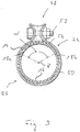
- a clamp 24 surrounds the connection region 26 of the first tube such that the slit 18 substantially circumferentially spans the connection region 26 in the entire axial extension region and thus radially against the second Tube 16 pressing pipe clamp 24 is covered.
- this object is achieved by a pipe, in particular exhaust pipe for an exhaust system of an internal combustion engine, wherein at least one axial pipe end a connection region for connecting the tube extending in the direction of a pipe axis with a in the Connection area to be inserted further tube is provided, wherein the connecting portion comprises at least one slot, wherein the slot has a tube end closer to the first slot portion and a further axially from the tube end and circumferentially offset relative to the first slot portion second slot region.
- This tube is characterized in that the connecting portion comprises two slots, wherein the second slot portions of the two slots in the circumferential direction with respect to the first slot portions are offset from each other or away from each other.
- the inventive design of a connecting region of a tube with a plurality, in particular two slots an improved deformability of the tube is ensured in its connection region.
- the first slit regions, when the second slit regions are offset from each other have a larger mutual distance than the second slit regions, or, when the second slit regions are offset from each other, a smaller mutual one Distance than the second slot areas, in conjunction with the better deformability of the tube and the distortion occurring in the circumferential direction during reduction of the respective slot width ensures an improved sealing effect.
- the first slot regions and the second slot regions are bounded in the circumferential direction by an inner slot edge facing the respective other slot and an outer slot edge facing away from the respective other slot. and that an angular distance of the inner slot edges of the first slot regions is less than 180 ° in their region adjoining the tube end, preferably in the range of 110 ° to 130 °, preferably approximately 120 °.
- the pipe constructed according to the invention it can be provided that, in at least one slot area, preferably the first slot area and the second slot area, of at least one slot, preferably two slots, the outer slot edge and / or the inner slot edge extend substantially in the direction the pipe longitudinal axis extends and / or the outer slot edge and the inner slot edge extending substantially parallel to each other.
- At least one slot area preferably the first slot area and the second slot area of at least one slot, preferably both slots, the outer slot edge and the inner slot edge have a circumferential distance in the range of 3 mm to 5 mm, preferably about 4 mm.
- the first slot regions of the two slots may have substantially the same extension length in the direction of the tube longitudinal axis. Furthermore, the second slot regions of the two slots in the direction of the tube longitudinal axis can have substantially the same extension length.
- the two slots are of essentially mirror-symmetrical design with respect to an axis of symmetry which is essentially parallel to the tube longitudinal axis.
- the inner slot edges of the first and second slot portions of the two slots may be interconnected by inner transition edges and the outer slot edges of the first and second slot portions of the two slots may be interconnected by outer transition edges. It is advantageous to obtain a sealing effect supporting mutual investment of inner and outer transition edges, the inner transition edge and / or the outer transition edge of at least one, preferably both slots angled relative to a circumferentially extending reference line.
- the design may be such that in at least one, preferably two, slots, the inner transition edge and the outer transition edge are angled in the same direction with respect to the reference line and one of the transition edges, preferably the inner transition edge, is more angled relative to the reference line than the other Transition edges, preferably the outer transition edge, wherein one of the more angled transition edge, preferably the inner transition edge, closer end of the less angled transition edge, preferably the outer transition edge, axially between the two ends of the more angled transition edge, preferably the inner transition edge lies.
- the inner transition edge and the outer transition edge may be angled in opposite directions relative to the reference line such that one of the transition edges, preferably the outer transition edge forms an undercut with the adjoining slot edge of the first slot region. wherein one of the other transition edge, preferably the inner transition edge, closer end of a transition edge, preferably the outer transition edge, axially between the two ends of the other transition edge, preferably the inner transition edge lies.
- the outer transition edges of the two slots are angled in opposite directions and / or to the same extent with respect to the reference line, and / or that the inner transition edges of the two slots in opposite directions or and angled to the same extent with respect to the reference line.
- the invention further relates to a tube assembly comprising a first tube constructed in accordance with the principles of the present invention and a second tube inserted into a connection region of the first tube, further comprising a first tube surrounding the connection region and the first tube radially pressing against the second tube pipe clamp.
- the pipe clamp substantially completely covers the slots provided in the connection region in the axial direction, preferably such that a slot bottom of the slots removed from the pipe end overlaps the pipe clamp is or / and lying between the respective slot bottom and the transition edges of a respective slot slot area is completely covered by the pipe clamp.
- the sealing effect to be generated in connection with the pipe clamp can be optimized in that a clamp lock region of the pipe clamp in the connection region of the first pipe in a peripheral region with a smaller angular extent between the two slots, preferably in the circumferential direction in Essentially centered between the two slots, is arranged.
- two slots 18a, 18b are provided in the connecting region 26 of the tube 14, in which the other tube 16 is to be inserted.
- Each of the two slots 18a, 18b has two slot areas 20a, 22a and 20b, 22b, which are preferably open to each other.
- the two first slot regions 20a, 20b of the two slots 18a, 18b are open in the direction of a tube longitudinal axis A.
- the two slot regions 22a, 22b adjoining the first slot regions 20a, 20b each provide a slot bottom 28a, 28b, that is to say the respective axial end of a slot 18a or 18b.
- Each of the first slot portions 20a, 20b of the two slots 18a, 18b is bounded in the direction away from the other slot by an outer slot edge 30a, 30b and in the direction of the other slot by an inner slot edge 32a, 32b in the circumferential direction.
- each of the Both slots 18a, 18b, the outer and inner slot edges 30a, 30b and 32a, 32b parallel to each other and substantially parallel to the tube longitudinal axis A, so that each first slot portion 20a, 20b has a substantially constant circumferential width B 1, for example, about 4 mm ,
- Each of the second slot regions 22a, 22b of the two slots 18a, 18b is delimited by an outer slot edge 34a, 34b on its peripheral side facing away from each other slot and by an inner slot edge 36a, 36b on its peripheral side facing the respective other slot.
- the outer and inner slot edges 34a, 34b and 36a, 36b of the two second slot portions 22a, 22b extend to each other and to the tube longitudinal axis A preferably substantially parallel, so that the second slot portions 22a, 22b a substantially constant slot width B 2nd for example, of about 4 mm.
- the respective first slot area 20a, 20b and second slot area 22a, 22b have the same circumferential width.
- the Fig. 4 clearly shows that in each of the two slots 18a, 18b, the second slot portion 22a, 22b is circumferentially offset with respect to the first slot portion 20a, 20b.
- the two second slot regions 22a, 22b are mutually opposite in relation to the respectively assigned first slot region 20a, 20b, in particular offset from one another.
- the second slot regions 22a, 22b thus have a smaller mutual distance, for example relative to their respective outer slot edges 34a, 34b or inner slot edges 36a, 36b, than the two first slot regions 20a, 20b.
- an offset V thus present in each of the two slots 18a, 18b between the respective first slot area 20a, 20b and second slot area 22a, 22b can be substantially the circumferential width B 1 or B 2 of a respective slot 18a, 18b in its two slot areas 20a , 20b and 22a, 22b, respectively.
- the inner peripheral edge 32a of the first slot portion 20a substantially axially continues the outer peripheral edge 34a of the second slot portion 22a in the direction of the tube longitudinal axis A, or has substantially no circumferential offset thereto.
- the angular distance of the respective inner peripheral edges 32a, 32b of the two first slot portions 20a may be about 120 °.
- the corresponding angular distance of the inner slot edges 36a, 36b of the second slot areas 22a, 22b is then correspondingly smaller.
- the design is preferably such that the two slots 18a, 18b are designed to be essentially mirror-symmetrical to each other with respect to an axis of symmetry S parallel to the pipe longitudinal axis A.
- the offset V of the two slot portions 20a, 22a and 20b, 22b provided in each of the slots 18a, 18b is substantially introduced by interconnecting the respective outer slot edges 30a, 34a of the slot 18a by an outer transition edge 38a inner slot edges 32a, 36a of this slot 18a are interconnected by an inner transition edge 40a.
- the outer slot edges 30b, 34b of the slot 18b are interconnected by an outer transition edge 38b, while the inner slot edges 32b, 36b of the slot 18b are interconnected by an inner transition edge 40b.
- the inner and outer transition edges 38a, 40a and 38b, 40b are angled with respect to a substantially circumferentially extending reference line R, so do not extend parallel and not orthogonal thereto.
- the transition edges 38a, 40a of the slot 18a and the transition edges 38b, 40b of the slot 18b are mutually angled relative to the reference line R, while each of the slots 18a, 18b in each case present transitional edges 38a, 40a and 38b, 40b to each other are angled in the same direction, but to a different extent with respect to the reference line R.
- the respective inner transition edges 40a, 40b are more angled with respect to the reference line R than the respective outer transition edges 38a, 38b.
- a similar configuration is also present at the inner transition edge 40b nearer end 42b of the outer transition edge 38b of the slot 18b with respect to the ends 44b, 46b of the inner transition edge 40b.
- the tube 16 is inserted into the connecting portion 26 of the tube 14, to an extent which is greater than the axial extension length of the two slots 18 a, 18 b, so that the tube 16 with its in the connecting region 26th pushed in area completely covers the two slots 18a, 18b in the direction of the tube longitudinal axis A.
- the clamp 24 is applied or the possibly already applied clamp 24 is positioned such that a clamp lock 48 thereof, in which Missionsend Schemee a surrounding the connecting portion 26, band-like clamp body 50, for example by means of a bolt 52 are braced against each other, positioned so that he is centrally positioned between the two slots 18a, 18b and that in the peripheral region 54 of the tube 14 with a smaller angular extent.
- the circumferential width of the two slots 18a, 18b also decreases since the respective outer slot edges 30a, 34a and 30b, 34b move circumferentially toward the respective inner slot edges 32a, 36a, 32b, 36b.
- the ends 42a, 42b of the respective outer transition edges 38, 38b approach and intersect, respectively, the respective inner transition edges 40a, 40b.
- the clamp body 50 of the pipe clamp 48 is further dimensioned so that in the direction of the tube longitudinal axis R, the slots 18a, 18b substantially completely covers, in particular the respective second slot portion 22a, 22b between the slot bottom 28a, 28b and in mutual contact or intersecting transition edges 38a, 40a and 38b, 40b completely covered.
- the slots 18a, 18b in particular in their respective second slot regions 22a, 22b not only in the direction of the tube longitudinal axis A, but also closed radially outward, so that an outlet of the guided in the tubes 14, 16 medium, for example, that of an internal combustion engine Exhaust gas emitted by a vehicle is excluded.
- the principles of the present invention can also be implemented in a structurally different embodiment of the two slots.
- the opposing offset of the respective second slot regions with respect to the first slot regions can also be realized by an offset of the second slot regions from each other or the symmetry axis, so that the two second slot regions have a greater circumferential distance or angular distance from one another than the two first slot regions .
- the Anwinkelung of the transition edges are also chosen so that the respective outer transition edge is more inclined with respect to the reference line, as the inner transition edge, so that the outer transition edge nearer end of the inner transition edge at decrease the circumferential width of a respective slot cuts into the outer transition edge.
- the undercut formed by angling the transition edge may also be provided in the region of the inner transition edge.
- the or at least some of the slot regions may also run at an angle with respect to the tube longitudinal axis or a line parallel thereto, for example in such a sense that the slots or
- Slit areas starting from the pipe end, approach each other or away from each other.
- the in Fig. 4 recognizable essentially mirror-symmetrical design with respect to a uniform sealing effect in all peripheral areas is particularly advantageous.
- the two slots may be designed differently from each other, in particular be different dimensions or in the transition region between the respective first and second slot areas have a mutually different extent of each existing offset.
Landscapes
- Engineering & Computer Science (AREA)
- General Engineering & Computer Science (AREA)
- Mechanical Engineering (AREA)
- Chemical & Material Sciences (AREA)
- Combustion & Propulsion (AREA)
- Rigid Pipes And Flexible Pipes (AREA)
Applications Claiming Priority (1)
| Application Number | Priority Date | Filing Date | Title |
|---|---|---|---|
| DE102017110217.5A DE102017110217A1 (de) | 2017-05-11 | 2017-05-11 | Rohr, insbesondere Abgasführungsrohr |
Publications (2)
| Publication Number | Publication Date |
|---|---|
| EP3401584A1 true EP3401584A1 (fr) | 2018-11-14 |
| EP3401584B1 EP3401584B1 (fr) | 2020-07-08 |
Family
ID=62104190
Family Applications (1)
| Application Number | Title | Priority Date | Filing Date |
|---|---|---|---|
| EP18170354.7A Active EP3401584B1 (fr) | 2017-05-11 | 2018-05-02 | Tuyau, en particulier tuyau de gaz d'échappement |
Country Status (4)
| Country | Link |
|---|---|
| US (1) | US11125138B2 (fr) |
| EP (1) | EP3401584B1 (fr) |
| CN (1) | CN108868987B (fr) |
| DE (1) | DE102017110217A1 (fr) |
Families Citing this family (1)
| Publication number | Priority date | Publication date | Assignee | Title |
|---|---|---|---|---|
| ES2972373T3 (es) * | 2020-03-23 | 2024-06-12 | Orthofix Srl | Puntal de fijación externa mejorado |
Citations (8)
| Publication number | Priority date | Publication date | Assignee | Title |
|---|---|---|---|---|
| US1661674A (en) * | 1925-07-10 | 1928-03-06 | Osborn Milton | Stovepipe attachment |
| US4113289A (en) * | 1977-03-03 | 1978-09-12 | Donaldson Company, Inc. | Exhaust system and muffler lap joint |
| US4629226A (en) * | 1985-04-16 | 1986-12-16 | Bks Company | Pipe lap joint with collapsible sealing zone and band clamp |
| US5588680A (en) * | 1994-12-20 | 1996-12-31 | Bks Company | Pipe lap joint with improved collapsible sealing zone |
| US20060071471A1 (en) * | 2004-10-04 | 2006-04-06 | Breeze-Torca Products, Llc | Pipe lap joint with improved sealing slot for increased circumferential closure |
| DE102006057881C5 (de) * | 2006-12-08 | 2010-07-22 | Norma Germany Gmbh | Spannbare Schelle |
| CN202612913U (zh) * | 2012-04-09 | 2012-12-19 | 天纳克同泰(大连)排气系统有限公司 | 一种可定位的管件 |
| DE102015201489A1 (de) * | 2014-03-20 | 2015-09-24 | Harley-Davidson Motor Company Group, LLC | Mehrteilige Auspufftopfumhausung |
Family Cites Families (8)
| Publication number | Priority date | Publication date | Assignee | Title |
|---|---|---|---|---|
| JP2599144B2 (ja) | 1987-09-26 | 1997-04-09 | ヤマハ発動機株式会社 | 自動二輪車等の車両における排気装置 |
| DE19639324C2 (de) * | 1996-09-25 | 1998-12-03 | Daimler Benz Ag | Rohrschelle mit einer zum Anziehen dienenden Kopfschraube |
| US6089624A (en) * | 1998-05-12 | 2000-07-18 | Bks Company | Pipe lap joint with improved collapsible slot |
| US7775561B2 (en) * | 2006-02-01 | 2010-08-17 | Tru-Flex Metal Hose Corp. | Exhaust pipe joint with insert |
| JP2012171596A (ja) | 2011-02-24 | 2012-09-10 | Hitachi Constr Mach Co Ltd | 建設機械 |
| CN203856558U (zh) | 2014-04-03 | 2014-10-01 | 郑州精益达汽车零部件有限公司 | 一种新型排气管 |
| CN204175408U (zh) | 2014-10-28 | 2015-02-25 | 瑞安市鸿源汽车部件有限公司 | 便于拆装清洗的汽车排气管 |
| WO2018058120A1 (fr) * | 2016-09-26 | 2018-03-29 | Norma U.S. Holding Llc | Collier de serrage pour extrémités de tuyau se chevauchant |
-
2017
- 2017-05-11 DE DE102017110217.5A patent/DE102017110217A1/de not_active Withdrawn
-
2018
- 2018-05-02 EP EP18170354.7A patent/EP3401584B1/fr active Active
- 2018-05-10 US US15/975,991 patent/US11125138B2/en active Active
- 2018-05-10 CN CN201810440030.2A patent/CN108868987B/zh active Active
Patent Citations (8)
| Publication number | Priority date | Publication date | Assignee | Title |
|---|---|---|---|---|
| US1661674A (en) * | 1925-07-10 | 1928-03-06 | Osborn Milton | Stovepipe attachment |
| US4113289A (en) * | 1977-03-03 | 1978-09-12 | Donaldson Company, Inc. | Exhaust system and muffler lap joint |
| US4629226A (en) * | 1985-04-16 | 1986-12-16 | Bks Company | Pipe lap joint with collapsible sealing zone and band clamp |
| US5588680A (en) * | 1994-12-20 | 1996-12-31 | Bks Company | Pipe lap joint with improved collapsible sealing zone |
| US20060071471A1 (en) * | 2004-10-04 | 2006-04-06 | Breeze-Torca Products, Llc | Pipe lap joint with improved sealing slot for increased circumferential closure |
| DE102006057881C5 (de) * | 2006-12-08 | 2010-07-22 | Norma Germany Gmbh | Spannbare Schelle |
| CN202612913U (zh) * | 2012-04-09 | 2012-12-19 | 天纳克同泰(大连)排气系统有限公司 | 一种可定位的管件 |
| DE102015201489A1 (de) * | 2014-03-20 | 2015-09-24 | Harley-Davidson Motor Company Group, LLC | Mehrteilige Auspufftopfumhausung |
Also Published As
| Publication number | Publication date |
|---|---|
| DE102017110217A1 (de) | 2018-11-29 |
| US20180328256A1 (en) | 2018-11-15 |
| EP3401584B1 (fr) | 2020-07-08 |
| CN108868987A (zh) | 2018-11-23 |
| US11125138B2 (en) | 2021-09-21 |
| CN108868987B (zh) | 2021-10-15 |
Similar Documents
| Publication | Publication Date | Title |
|---|---|---|
| DE3149833C2 (de) | Vorrichtung zum Verbinden von Bundrohren | |
| DE102004050300B4 (de) | Profilschelle | |
| DE69430403T2 (de) | Selbstspannende Klemmschellenstruktur | |
| DE102015100552B3 (de) | Stützring für ein Abgasführungssystem | |
| EP1526317A2 (fr) | Tuyau flexible avec un bord sur l'extrémité | |
| DE3347503A1 (de) | Selbstsichernder sperrbolzen | |
| EP3401584B1 (fr) | Tuyau, en particulier tuyau de gaz d'échappement | |
| EP0959288B1 (fr) | Collier de serrage | |
| DE3104518A1 (de) | Anschlussarmatur | |
| DE29723073U1 (de) | Dichtungsvorrichtung zum abdichtenden Durchführen mindestens einer Leitung | |
| EP0288993B2 (fr) | Dispositif pour assemblage des extrémités coaxiales de deux tuyaux sans manchons | |
| EP0717204A1 (fr) | Goujon de sécurité, qui peut être inséré dans des trous passant dans des pièces jusqu'à une butée | |
| DE102021115962A1 (de) | Schalldämpfer und Verfahren zur Herstellung eines Schalldämpfers | |
| DE3029771A1 (de) | Schubsicherung fuer muffenverbindungen von kunststoffrohren | |
| EP3828397B1 (fr) | Unité de raccordement | |
| EP1611387B1 (fr) | Raccord de tuyaux | |
| EP3734037B1 (fr) | Boîtier pour une installation d'échappement d'un moteur à combustion interne d'un véhicule | |
| CH677817A5 (en) | U=bolt pipe clamp | |
| DE10024894C1 (de) | Mehrreihiges Wälzlager | |
| EP3460306A1 (fr) | Tuyau doté d'une bride de connexion | |
| DE102007013560B4 (de) | Einstellbarer Segmentbogen | |
| DE202016105158U1 (de) | Bauteil mit einer Befestigungsöffnung sowie Befestigungsbaugruppe | |
| EP1251304A1 (fr) | Tuyau, notamment en matière plastique ou composite | |
| DE10349145A1 (de) | Regenrinnenablaufbogen | |
| CH693542A5 (de) | Abgedichteter Rohrbogen. |
Legal Events
| Date | Code | Title | Description |
|---|---|---|---|
| PUAI | Public reference made under article 153(3) epc to a published international application that has entered the european phase |
Free format text: ORIGINAL CODE: 0009012 |
|
| STAA | Information on the status of an ep patent application or granted ep patent |
Free format text: STATUS: THE APPLICATION HAS BEEN PUBLISHED |
|
| AK | Designated contracting states |
Kind code of ref document: A1 Designated state(s): AL AT BE BG CH CY CZ DE DK EE ES FI FR GB GR HR HU IE IS IT LI LT LU LV MC MK MT NL NO PL PT RO RS SE SI SK SM TR |
|
| AX | Request for extension of the european patent |
Extension state: BA ME |
|
| STAA | Information on the status of an ep patent application or granted ep patent |
Free format text: STATUS: REQUEST FOR EXAMINATION WAS MADE |
|
| 17P | Request for examination filed |
Effective date: 20190212 |
|
| RBV | Designated contracting states (corrected) |
Designated state(s): AL AT BE BG CH CY CZ DE DK EE ES FI FR GB GR HR HU IE IS IT LI LT LU LV MC MK MT NL NO PL PT RO RS SE SI SK SM TR |
|
| STAA | Information on the status of an ep patent application or granted ep patent |
Free format text: STATUS: EXAMINATION IS IN PROGRESS |
|
| 17Q | First examination report despatched |
Effective date: 20190411 |
|
| GRAP | Despatch of communication of intention to grant a patent |
Free format text: ORIGINAL CODE: EPIDOSNIGR1 |
|
| STAA | Information on the status of an ep patent application or granted ep patent |
Free format text: STATUS: GRANT OF PATENT IS INTENDED |
|
| GRAJ | Information related to disapproval of communication of intention to grant by the applicant or resumption of examination proceedings by the epo deleted |
Free format text: ORIGINAL CODE: EPIDOSDIGR1 |
|
| STAA | Information on the status of an ep patent application or granted ep patent |
Free format text: STATUS: EXAMINATION IS IN PROGRESS |
|
| GRAP | Despatch of communication of intention to grant a patent |
Free format text: ORIGINAL CODE: EPIDOSNIGR1 |
|
| INTG | Intention to grant announced |
Effective date: 20200120 |
|
| STAA | Information on the status of an ep patent application or granted ep patent |
Free format text: STATUS: GRANT OF PATENT IS INTENDED |
|
| INTC | Intention to grant announced (deleted) | ||
| INTG | Intention to grant announced |
Effective date: 20200220 |
|
| GRAS | Grant fee paid |
Free format text: ORIGINAL CODE: EPIDOSNIGR3 |
|
| GRAA | (expected) grant |
Free format text: ORIGINAL CODE: 0009210 |
|
| STAA | Information on the status of an ep patent application or granted ep patent |
Free format text: STATUS: THE PATENT HAS BEEN GRANTED |
|
| AK | Designated contracting states |
Kind code of ref document: B1 Designated state(s): AL AT BE BG CH CY CZ DE DK EE ES FI FR GB GR HR HU IE IS IT LI LT LU LV MC MK MT NL NO PL PT RO RS SE SI SK SM TR |
|
| REG | Reference to a national code |
Ref country code: AT Ref legal event code: REF Ref document number: 1288832 Country of ref document: AT Kind code of ref document: T Effective date: 20200715 Ref country code: CH Ref legal event code: EP |
|
| REG | Reference to a national code |
Ref country code: DE Ref legal event code: R096 Ref document number: 502018001822 Country of ref document: DE |
|
| REG | Reference to a national code |
Ref country code: SE Ref legal event code: TRGR |
|
| REG | Reference to a national code |
Ref country code: IE Ref legal event code: FG4D Free format text: LANGUAGE OF EP DOCUMENT: GERMAN |
|
| REG | Reference to a national code |
Ref country code: LT Ref legal event code: MG4D |
|
| REG | Reference to a national code |
Ref country code: NL Ref legal event code: MP Effective date: 20200708 |
|
| PG25 | Lapsed in a contracting state [announced via postgrant information from national office to epo] |
Ref country code: BG Free format text: LAPSE BECAUSE OF FAILURE TO SUBMIT A TRANSLATION OF THE DESCRIPTION OR TO PAY THE FEE WITHIN THE PRESCRIBED TIME-LIMIT Effective date: 20201008 Ref country code: ES Free format text: LAPSE BECAUSE OF FAILURE TO SUBMIT A TRANSLATION OF THE DESCRIPTION OR TO PAY THE FEE WITHIN THE PRESCRIBED TIME-LIMIT Effective date: 20200708 Ref country code: NO Free format text: LAPSE BECAUSE OF FAILURE TO SUBMIT A TRANSLATION OF THE DESCRIPTION OR TO PAY THE FEE WITHIN THE PRESCRIBED TIME-LIMIT Effective date: 20201008 Ref country code: GR Free format text: LAPSE BECAUSE OF FAILURE TO SUBMIT A TRANSLATION OF THE DESCRIPTION OR TO PAY THE FEE WITHIN THE PRESCRIBED TIME-LIMIT Effective date: 20201009 Ref country code: HR Free format text: LAPSE BECAUSE OF FAILURE TO SUBMIT A TRANSLATION OF THE DESCRIPTION OR TO PAY THE FEE WITHIN THE PRESCRIBED TIME-LIMIT Effective date: 20200708 Ref country code: PT Free format text: LAPSE BECAUSE OF FAILURE TO SUBMIT A TRANSLATION OF THE DESCRIPTION OR TO PAY THE FEE WITHIN THE PRESCRIBED TIME-LIMIT Effective date: 20201109 Ref country code: LT Free format text: LAPSE BECAUSE OF FAILURE TO SUBMIT A TRANSLATION OF THE DESCRIPTION OR TO PAY THE FEE WITHIN THE PRESCRIBED TIME-LIMIT Effective date: 20200708 Ref country code: FI Free format text: LAPSE BECAUSE OF FAILURE TO SUBMIT A TRANSLATION OF THE DESCRIPTION OR TO PAY THE FEE WITHIN THE PRESCRIBED TIME-LIMIT Effective date: 20200708 |
|
| PG25 | Lapsed in a contracting state [announced via postgrant information from national office to epo] |
Ref country code: IS Free format text: LAPSE BECAUSE OF FAILURE TO SUBMIT A TRANSLATION OF THE DESCRIPTION OR TO PAY THE FEE WITHIN THE PRESCRIBED TIME-LIMIT Effective date: 20201108 Ref country code: PL Free format text: LAPSE BECAUSE OF FAILURE TO SUBMIT A TRANSLATION OF THE DESCRIPTION OR TO PAY THE FEE WITHIN THE PRESCRIBED TIME-LIMIT Effective date: 20200708 Ref country code: LV Free format text: LAPSE BECAUSE OF FAILURE TO SUBMIT A TRANSLATION OF THE DESCRIPTION OR TO PAY THE FEE WITHIN THE PRESCRIBED TIME-LIMIT Effective date: 20200708 Ref country code: RS Free format text: LAPSE BECAUSE OF FAILURE TO SUBMIT A TRANSLATION OF THE DESCRIPTION OR TO PAY THE FEE WITHIN THE PRESCRIBED TIME-LIMIT Effective date: 20200708 |
|
| PG25 | Lapsed in a contracting state [announced via postgrant information from national office to epo] |
Ref country code: NL Free format text: LAPSE BECAUSE OF FAILURE TO SUBMIT A TRANSLATION OF THE DESCRIPTION OR TO PAY THE FEE WITHIN THE PRESCRIBED TIME-LIMIT Effective date: 20200708 |
|
| REG | Reference to a national code |
Ref country code: DE Ref legal event code: R097 Ref document number: 502018001822 Country of ref document: DE |
|
| PG25 | Lapsed in a contracting state [announced via postgrant information from national office to epo] |
Ref country code: SM Free format text: LAPSE BECAUSE OF FAILURE TO SUBMIT A TRANSLATION OF THE DESCRIPTION OR TO PAY THE FEE WITHIN THE PRESCRIBED TIME-LIMIT Effective date: 20200708 Ref country code: IT Free format text: LAPSE BECAUSE OF FAILURE TO SUBMIT A TRANSLATION OF THE DESCRIPTION OR TO PAY THE FEE WITHIN THE PRESCRIBED TIME-LIMIT Effective date: 20200708 Ref country code: EE Free format text: LAPSE BECAUSE OF FAILURE TO SUBMIT A TRANSLATION OF THE DESCRIPTION OR TO PAY THE FEE WITHIN THE PRESCRIBED TIME-LIMIT Effective date: 20200708 Ref country code: CZ Free format text: LAPSE BECAUSE OF FAILURE TO SUBMIT A TRANSLATION OF THE DESCRIPTION OR TO PAY THE FEE WITHIN THE PRESCRIBED TIME-LIMIT Effective date: 20200708 Ref country code: DK Free format text: LAPSE BECAUSE OF FAILURE TO SUBMIT A TRANSLATION OF THE DESCRIPTION OR TO PAY THE FEE WITHIN THE PRESCRIBED TIME-LIMIT Effective date: 20200708 Ref country code: RO Free format text: LAPSE BECAUSE OF FAILURE TO SUBMIT A TRANSLATION OF THE DESCRIPTION OR TO PAY THE FEE WITHIN THE PRESCRIBED TIME-LIMIT Effective date: 20200708 |
|
| PLBE | No opposition filed within time limit |
Free format text: ORIGINAL CODE: 0009261 |
|
| STAA | Information on the status of an ep patent application or granted ep patent |
Free format text: STATUS: NO OPPOSITION FILED WITHIN TIME LIMIT |
|
| PG25 | Lapsed in a contracting state [announced via postgrant information from national office to epo] |
Ref country code: AL Free format text: LAPSE BECAUSE OF FAILURE TO SUBMIT A TRANSLATION OF THE DESCRIPTION OR TO PAY THE FEE WITHIN THE PRESCRIBED TIME-LIMIT Effective date: 20200708 |
|
| 26N | No opposition filed |
Effective date: 20210409 |
|
| PG25 | Lapsed in a contracting state [announced via postgrant information from national office to epo] |
Ref country code: SK Free format text: LAPSE BECAUSE OF FAILURE TO SUBMIT A TRANSLATION OF THE DESCRIPTION OR TO PAY THE FEE WITHIN THE PRESCRIBED TIME-LIMIT Effective date: 20200708 |
|
| REG | Reference to a national code |
Ref country code: DE Ref legal event code: R082 Ref document number: 502018001822 Country of ref document: DE Representative=s name: RUTTENSPERGER LACHNIT TROSSIN GOMOLL, PATENT- , DE Ref country code: DE Ref legal event code: R081 Ref document number: 502018001822 Country of ref document: DE Owner name: PUREM GMBH, DE Free format text: FORMER OWNER: EBERSPAECHER EXHAUST TECHNOLOGY GMBH & CO. KG, 66539 NEUNKIRCHEN, DE |
|
| PG25 | Lapsed in a contracting state [announced via postgrant information from national office to epo] |
Ref country code: SI Free format text: LAPSE BECAUSE OF FAILURE TO SUBMIT A TRANSLATION OF THE DESCRIPTION OR TO PAY THE FEE WITHIN THE PRESCRIBED TIME-LIMIT Effective date: 20200708 |
|
| REG | Reference to a national code |
Ref country code: GB Ref legal event code: 732E Free format text: REGISTERED BETWEEN 20210902 AND 20210908 |
|
| REG | Reference to a national code |
Ref country code: CH Ref legal event code: PL |
|
| PG25 | Lapsed in a contracting state [announced via postgrant information from national office to epo] |
Ref country code: CH Free format text: LAPSE BECAUSE OF NON-PAYMENT OF DUE FEES Effective date: 20210531 Ref country code: MC Free format text: LAPSE BECAUSE OF FAILURE TO SUBMIT A TRANSLATION OF THE DESCRIPTION OR TO PAY THE FEE WITHIN THE PRESCRIBED TIME-LIMIT Effective date: 20200708 Ref country code: LI Free format text: LAPSE BECAUSE OF NON-PAYMENT OF DUE FEES Effective date: 20210531 Ref country code: LU Free format text: LAPSE BECAUSE OF NON-PAYMENT OF DUE FEES Effective date: 20210502 |
|
| REG | Reference to a national code |
Ref country code: BE Ref legal event code: MM Effective date: 20210531 |
|
| PG25 | Lapsed in a contracting state [announced via postgrant information from national office to epo] |
Ref country code: IE Free format text: LAPSE BECAUSE OF NON-PAYMENT OF DUE FEES Effective date: 20210502 |
|
| PG25 | Lapsed in a contracting state [announced via postgrant information from national office to epo] |
Ref country code: BE Free format text: LAPSE BECAUSE OF NON-PAYMENT OF DUE FEES Effective date: 20210531 |
|
| PGFP | Annual fee paid to national office [announced via postgrant information from national office to epo] |
Ref country code: SE Payment date: 20220523 Year of fee payment: 5 |
|
| PG25 | Lapsed in a contracting state [announced via postgrant information from national office to epo] |
Ref country code: CY Free format text: LAPSE BECAUSE OF FAILURE TO SUBMIT A TRANSLATION OF THE DESCRIPTION OR TO PAY THE FEE WITHIN THE PRESCRIBED TIME-LIMIT Effective date: 20200708 |
|
| PG25 | Lapsed in a contracting state [announced via postgrant information from national office to epo] |
Ref country code: HU Free format text: LAPSE BECAUSE OF FAILURE TO SUBMIT A TRANSLATION OF THE DESCRIPTION OR TO PAY THE FEE WITHIN THE PRESCRIBED TIME-LIMIT; INVALID AB INITIO Effective date: 20180502 |
|
| REG | Reference to a national code |
Ref country code: SE Ref legal event code: EUG |
|
| PG25 | Lapsed in a contracting state [announced via postgrant information from national office to epo] |
Ref country code: SE Free format text: LAPSE BECAUSE OF NON-PAYMENT OF DUE FEES Effective date: 20230503 |
|
| PG25 | Lapsed in a contracting state [announced via postgrant information from national office to epo] |
Ref country code: MK Free format text: LAPSE BECAUSE OF FAILURE TO SUBMIT A TRANSLATION OF THE DESCRIPTION OR TO PAY THE FEE WITHIN THE PRESCRIBED TIME-LIMIT Effective date: 20200708 |
|
| REG | Reference to a national code |
Ref country code: AT Ref legal event code: MM01 Ref document number: 1288832 Country of ref document: AT Kind code of ref document: T Effective date: 20230502 |
|
| PG25 | Lapsed in a contracting state [announced via postgrant information from national office to epo] |
Ref country code: AT Free format text: LAPSE BECAUSE OF NON-PAYMENT OF DUE FEES Effective date: 20230502 |
|
| PG25 | Lapsed in a contracting state [announced via postgrant information from national office to epo] |
Ref country code: AT Free format text: LAPSE BECAUSE OF NON-PAYMENT OF DUE FEES Effective date: 20230502 |
|
| PG25 | Lapsed in a contracting state [announced via postgrant information from national office to epo] |
Ref country code: MT Free format text: LAPSE BECAUSE OF FAILURE TO SUBMIT A TRANSLATION OF THE DESCRIPTION OR TO PAY THE FEE WITHIN THE PRESCRIBED TIME-LIMIT Effective date: 20200708 |
|
| PGFP | Annual fee paid to national office [announced via postgrant information from national office to epo] |
Ref country code: DE Payment date: 20250519 Year of fee payment: 8 |
|
| PGFP | Annual fee paid to national office [announced via postgrant information from national office to epo] |
Ref country code: GB Payment date: 20250522 Year of fee payment: 8 |
|
| PGFP | Annual fee paid to national office [announced via postgrant information from national office to epo] |
Ref country code: FR Payment date: 20250521 Year of fee payment: 8 |
|
| PG25 | Lapsed in a contracting state [announced via postgrant information from national office to epo] |
Ref country code: TR Free format text: LAPSE BECAUSE OF FAILURE TO SUBMIT A TRANSLATION OF THE DESCRIPTION OR TO PAY THE FEE WITHIN THE PRESCRIBED TIME-LIMIT Effective date: 20200708 |
|
| PGFP | Annual fee paid to national office [announced via postgrant information from national office to epo] |
Ref country code: AT Payment date: 20260410 Year of fee payment: 5 |