EP3401635A1 - Sonde de déclenchement par contact - Google Patents
Sonde de déclenchement par contact Download PDFInfo
- Publication number
- EP3401635A1 EP3401635A1 EP18168130.5A EP18168130A EP3401635A1 EP 3401635 A1 EP3401635 A1 EP 3401635A1 EP 18168130 A EP18168130 A EP 18168130A EP 3401635 A1 EP3401635 A1 EP 3401635A1
- Authority
- EP
- European Patent Office
- Prior art keywords
- displacement
- probe
- touch probe
- stylus
- trigger
- Prior art date
- Legal status (The legal status is an assumption and is not a legal conclusion. Google has not performed a legal analysis and makes no representation as to the accuracy of the status listed.)
- Granted
Links
Images



Classifications
-
- G—PHYSICS
- G01—MEASURING; TESTING
- G01B—MEASURING LENGTH, THICKNESS OR SIMILAR LINEAR DIMENSIONS; MEASURING ANGLES; MEASURING AREAS; MEASURING IRREGULARITIES OF SURFACES OR CONTOURS
- G01B5/00—Measuring arrangements characterised by the use of mechanical techniques
- G01B5/004—Measuring arrangements characterised by the use of mechanical techniques for measuring coordinates of points
- G01B5/008—Measuring arrangements characterised by the use of mechanical techniques for measuring coordinates of points using coordinate measuring machines
- G01B5/012—Contact-making feeler heads therefor
-
- G—PHYSICS
- G01—MEASURING; TESTING
- G01B—MEASURING LENGTH, THICKNESS OR SIMILAR LINEAR DIMENSIONS; MEASURING ANGLES; MEASURING AREAS; MEASURING IRREGULARITIES OF SURFACES OR CONTOURS
- G01B21/00—Measuring arrangements or details thereof, where the measuring technique is not covered by the other groups of this subclass, unspecified or not relevant
-
- G—PHYSICS
- G01—MEASURING; TESTING
- G01B—MEASURING LENGTH, THICKNESS OR SIMILAR LINEAR DIMENSIONS; MEASURING ANGLES; MEASURING AREAS; MEASURING IRREGULARITIES OF SURFACES OR CONTOURS
- G01B11/00—Measuring arrangements characterised by the use of optical techniques
- G01B11/002—Measuring arrangements characterised by the use of optical techniques for measuring two or more coordinates
- G01B11/005—Measuring arrangements characterised by the use of optical techniques for measuring two or more coordinates coordinate measuring machines
- G01B11/007—Measuring arrangements characterised by the use of optical techniques for measuring two or more coordinates coordinate measuring machines feeler heads therefor
-
- G—PHYSICS
- G01—MEASURING; TESTING
- G01B—MEASURING LENGTH, THICKNESS OR SIMILAR LINEAR DIMENSIONS; MEASURING ANGLES; MEASURING AREAS; MEASURING IRREGULARITIES OF SURFACES OR CONTOURS
- G01B7/00—Measuring arrangements characterised by the use of electric or magnetic techniques
- G01B7/004—Measuring arrangements characterised by the use of electric or magnetic techniques for measuring coordinates of points
- G01B7/008—Measuring arrangements characterised by the use of electric or magnetic techniques for measuring coordinates of points using coordinate measuring machines
- G01B7/012—Contact-making feeler heads therefor
Definitions
- the present invention concerns, in embodiments, a touch probe for measuring coordinate of points on workpieces, to be used in combination with a coordinate measuring machine (CMM), or another precise coordinate positioning system.
- CCM coordinate measuring machine
- Touch probes are well known in the field of dimensional metrology.
- a contact probe is releasably mounted on the mobile platform of a coordinate machine, and the machine is programmed to bring the touch probe in contact, by a feeler provided for this task, with the workpiece.
- the feeler typically consists of a precise ruby sphere at the tip of an elongated stylus and, when it touches the workpiece, the probe triggers an electric signal indicating that a contact has occurred. This signal is transmitted to a control unit that records the instantaneous position of the mobile platform and calculates the coordinates of the contact point on the workpiece.
- Scanning probes are used for acquiring a plurality of coordinate points along a path on a surface, on which the probe slides without losing contact. These are mounted on the coordinate measure machine similarly to the trigger ones but generate, in lieu of a digital trigger, a deflection signal that is a measure of the deflection of the feeler from its rest position.
- the probes can record the deflection in one, two, or three coordinates.
- trigger probes for example as in EP0764827 , US4270275 or US6760977 , the stylus is fastened onto a support with three radial pins arranged symmetrically, each resting on two spheres integrally united with the probe's body.
- This arrangement constitutes an isostatic connection with six independent contact points; the relative position of the stylus in relation to the probe's body is thus accurately defined.
- the trigger signal is generated when one of the pins lifts off the two spheres on which it normally rests, thus interrupting the electric contact between the two spheres.
- the sensitivity of the probe to an external force is not constant but varies according to its direction, exhibiting three lobes in the transverse plane corresponding to the directions of the three pins, and a different sensitivity to axial movement than to transverse ones.
- This variation of the sensitivity is detrimental to the repeatability of the touch triggering and thus to the quality of the measurement.
- Altering the arrangement of the pins, as described for example in EP1610087 or DE3713415 can reduce this anisotropy, without eliminating it completely, however.
- EP0360853 teaches a sensor in which the electric circuit is replaced by strain gauges that are directly sensitive to the force applied.
- Patent US8140287 describes a manner of correcting the anisotropy in the response of probes of this construction by a suitable correction matrix.
- the contact between the stylus and the part to be measured is detected by a vibration sensor or by an optical sensor.
- EP2629048 proposes a different kind of touch probe, utilisable both as a trigger and as a scanning probe, in which the contact and the deflection are deduced by changes in the distribution of light projected by a point source on an image sensor.
- US9157722 describes a touch probe whose trigger threshold is modified in response to the output of an embedded accelerometer.
- US7124514 and US9618312 disclose touch probes with multiple detectors. These devices are scanning probes and do not generate a trigger signal.
- the present invention proposes a touch probe that is free from the above shortcomings and exhibits low or no anisotropy, thanks to the features of the independent claim, namely a touch probe for dimensional measurements of coordinates of points on the surface of an object, comprising: a fixed member with a connection element for mounting the fixed member on a positioning platform of a coordinate-measuring machine; a stylus holder, elastically connected to the fixed member and comprising a reference element; a stylus on the stylus holder; one or more sensors, arranged to generate a displacement signal or several displacement signals in response to a motion of the reference element relative to the fixed member caused by a contact between the stylus and the object; a digital processor receiving the displacement signal or the displacement signals generated by the one or more sensors, the processor being programmed to generate a plurality of directional displacement signals representing the motion of the stylus holder in different directions, and to generate a plurality of trigger signals when an amplitude of any one of said directional displacement signals exceeds a corresponding threshold.
- Another, possibly independent, variant concerns a touch probe for dimensional measurements of coordinates of points on the surface of an object with a microcontroller arranged to generate a delayed trigger signal, retarded by a predetermined amount by the instant of contact between a feeler and a workpiece.
- this probe may comprise: a fixed member with a connection element for mounting the fixed member on a positioning platform of a coordinate-measuring machine; a stylus holder, elastically connected to the fixed member and comprising a reference element; a stylus on the stylus holder; one or more sensors, arranged to generate a displacement signal or several displacement signals in response to a motion of the reference element relative to the fixed member caused by a contact between the stylus and the object; a digital processor receiving the displacement signal or the displacement signals generated by the one or more sensors, the processor being programmed to generate a trigger signal signalling a contact between the stylus and the object, based upon a plurality of samples of the displacement signal or the displacement signals taken at a plurality of instants in time.
- the touch probe could in this case comprise a memory or a buffer to store the plurality of samples.
- the displacement signal or the displacement signals that the processor is programmed to use may represent the relative motion of the reference element in one, two, or more independent axes.
- the plurality of samples may be fed to a low-pass linear or nonlinear filter, for instance a running average, median filter, IIR/FIR filter, Savitzky-Golay, adaptive filter, in particular with a cut-off frequency higher than 50 Hz, preferably higher than100 Hz.
- the filter may be selected to attenuate certain frequencies generated by known noise sources.
- the processor may base its decision on whether or not to generate a trigger on a computed norm, for example a Euclidean norm of the displacement of the probe tip, of the probe holder, or of a displacement vector.
- the trigger may be generated only when a predetermined number of samples, or consecutive samples, exceeds a threshold, or when two consecutive samples of the displacement signal or of the displacement signals or of the measurement signals exceed a first threshold level, respectively a second threshold level.
- the trigger may be generated by the occurrence of a specific signal form in the displacement signal or signals, as detected by the micro-processor.
- the processor may be arranged to generate a delayed trigger signal that is retarded from the contact between the stylus and the object by a delay interval, the variable delay interval comprising a constant term and a slope-dependent term that is computed in the processor based on the time derivatives of the displacement signal, or of the displacement signals, or of the measurement signals.
- the generation of the delayed trigger may include the summation of a signal with an inverted and delayed copy of itself, and the comparison of the resulting sum with a predetermined threshold, which can be zero, to generate a delayed trigger signal.
- the touch probe may be programmed to determine an inhibit condition based on the samples of the displacement signal or the displacement signals taken at a plurality of instants in time, and to veto the generation of triggers while the inhibit condition is true, and could include a data interface adapted for uploading the samples of the displacement signal or the displacement signals taken at a plurality of instants in time to a host system, which could include the digital processor, remotely.
- the buffer of samples could also be uploaded to the host system at each trigger.
- Figure 1 illustrates schematically the structure of a touch probe according to an aspect of the invention.
- the probe 100 comprises a feeler that is composed, in this example, of an elongated stylus 45 with a calibrated sphere 47 at its tip.
- Other forms of feelers could be used in the frame of the invention, for example the sphere 47 could be replaced by a disc, and the stylus 45 needs not be straight, and could have multiple crossed arms.
- the stylus is attached to a stylus holder 40.
- the connection between stylus and holder is such that the stylus can easily be detached and replaced with another, according to the needs.
- the stylus is attached magnetically to the holder 40.
- the housing 62 of the probe 100 is fixed on a positioning platform 95, which may be the quill of a coordinate machine that is capable of moving in space, under the instructions of a CMM controller 30.
- the connection between the probe 100 and the positioning platform 95 may take various forms, the threaded rod represented in figure 1 being its most usual realization.
- the stylus holder 40 is connected to the fixed member 62 by resilient members 35 such that, when the feeler touches the workpiece 80, the holder 40 will be moved from its rest position, relative to the fixed member 62.
- the motion of the probe holder will be determined by the amplitude and direction of the displacement of the touch 47. In a lateral contact, the holder will rotate and, in an axial contact, the holder will rise axially.
- the probe detects tiny movements of the tip optically: when the stylus touches and is pushed against the workpiece, the resilient element 35 flexes and the holder 40 moves from its nominal rest position, in three dimensions.
- the holder 40 carries, opposite to the stylus 45 and inside the probe, an optical reference element 48, whose position is observed by an imaging device 73.
- the resilient elements 35 are relatively stiff, and their deformation is limited by design to a few ⁇ m.
- a safety mechanism including a magnetic contact and a safety spring, allows further tilt of the stylus without straining the probe. Should the tilt be increased beyond safe limits, the stylus falls from the probe body.
- the sensor comprises an optical reference element 48 and an imaging device 73.
- sensors can also be used.
- magnetic, Hall effect, capacitive or inductive sensors can be used to measure the 3D displacements of the stylus tip.
- capacitive or inductive sensors can be used to measure the 3D displacements of the stylus tip.
- linear encoders optical, inductive, capacitive or magnetic
- strain gauges can be used to measure the displacements along different directions.
- the reference element is a light-emitting diode (LED) 48.
- LED light-emitting diode
- Each movement of the stylus tip 47 generates a corresponding movement of the LED 48.
- the LED illuminates an optical sensor circuit 73 above it through an optical mask 76.
- the LED 48 follows the movements of the stylus relative to the probe body, such that any deflection of the stylus induces of necessity a displacement of the LED from its nominal position.
- the displacement along the axis of the probe (that we will denote conventionally by z) has different kinematics than the transverse ones, along coordinates x and y.
- the resilient elements 35 acts like a fulcrum for transverse movements (x, y), but transmits the axial movements (z) unchanged. Accordingly, the axial movements of the LED and that of the tip of the probe are essentially the same, while the transverse ones will be scaled in reason of the ratio between the length of the stylus and the distance between the LED and the rotation centre.
- the touch probe has a control unit 70, programmed to determine and measure the movements of the reference element 48 relative to its normal rest position from the image, decide from these whether the sphere 47 has touched the workpiece 80, and in this case generate a trigger signal 79 for the CMM controller 30.
- This arrangement is described in more detail by patent application EP2629048 , in the name of the applicant.
- FIG. 2 illustrates schematically the imaging device 73 and the processor 70.
- the image processing is carried out in two separate integrated circuits.
- the first one is an ASIC 74 that includes a preprogramed digital processor 71, comprising a correlation unit and a CORDIC arithmetic and trigonometric unit and, on the same silicon die, the image sensor 73.
- a programmable microcontroller 72 completes the image-processing system. Other arrangements would be possible, however.
- the ASIC 74 is in a transverse plane, which is orthogonal to the longitudinal axis z of the probe that comprises the x and y directions.
- the point directly above the LED 48 is marked with a cross. It measures tiny movements of the LED by observing an illumination pattern, projected by the LED through the periodic micro-lens array 76, on two arrays of photodiodes, denoted as L and R.
- the left and right arrays are aligned in y and read he same y-value.
- the x position on either array is parallax-shifted by the x separation between the arrays. This is used to extract the third coordinate z.
- the pre-processor 71 in the ASIC 74 computes the position of the illumination pattern in x and y for each array. It generates digital values that represent the position of the pattern relative to a rest position, in both coordinates, which are denoted ( x L , y L ), respectively ( x R , y R ). These values are calculated continuously by the pre-processor 71 in real-time, at a predetermined rate, for example every 25 ⁇ s.
- the microcontroller 72 reads the values ( x L , y L ), ( x R , y R ) and generates a trigger signal informing the CMM that the stylus has touched the workpiece. To this end, the microcontroller computes internally the 3D coordinates x,y,z :
- the pre-processor 71 and the microcontroller are arranged such that the values of x,y,z are directly provided in a common suitable unit, for example in nanometres. Should this not be the case, however, the microcontroller 72 could be programmed to introduce the necessary transformations.
- the microcontroller includes a memory area 72.4 that is used for storing a plurality of samples of x,y,z signals.
- This memory area which could be arranged as a circular buffer, stores the position of the LED 48 in a stated time interval.
- the memory area has a depth of 128 samples in x, y, and z, storing approximatively 3ms duration of data.
- This memory area is used to filter the signal, or to time-shift the trigger instant, as it will be described later on, but could also be transferred to the CMM controller 30 after each touch, thereby allowing an off-line correction of the coordinates of the contact point, based on the deviation profiles in x, y, z.
- the microcontroller embedded in the probe could deal simply with the storing of the displacement data in a suitable buffer, which is transferred to the CMM controller 30, acting as host system, and the computation of the trigger is carried out in the host system.
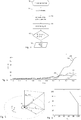
- FIG. 5 illustrates the geometry of the displacements.
- the contact moves the LED 48 along a displacement vector d whose components x, y, z are known to the microcontroller at all moments.
- and d t x 2 + y 2 that is the Euclidean norm of the 2-dimensional vector (x, y). Each of these is compared to a separate threshold: t a for the axial deviation, and t t for the transverse one.
- a trigger signal is sent to the CMM when either d a t a or d t t t . It is possible to reduce the variations of pretravel by choosing suitable threshold values. With long styli, t a will be chosen progressively larger than t t . Preferably, the CMM controller 30 communicates to the probe micro-controller 72 the length of the stylus. With this method, the pretravel can be made comparable for lateral and axial contacts; however, for oblique angles the pretravel will be bigger.
- Figure 4 plots the deviation d as a function of time in three distinct touches between the feeler 47 and a spherical reference body.
- Curve 230 corresponds to an axial contact, in which the probe moves downwards in the 'z' direction and the LED 48 and the stylus tip 47 move by the same amount.
- Curve 210 is the displacement during a lateral contact: the feeler 47 moves in the horizontal plane that contains the centre of the reference sphere, the deviation profile is much shallower, due to the lever arm between the stylus tip and the LED mentioned above.
- Curve 220 stands for an intermediate oblique approach.
- a portion of the transverse component of pretravel is due to the bending of the stylus which is not measured by the optical sensor.
- the pretravel due to bending can dominate over the pretravel for a rigid stylus, dependent on the material and geometry of the latter.
- the threshold for the axial trigger t a can be increased proportionately to equalize the pretravel with the transverse one.
- the value of at least one of the thresholds is not constant, but is computed by the processor based on the values of the directional displacements, for example, the value of t t could be chosen according to the value of d a , becoming progressively smaller when d a approaches t a , as illustrated in figure 6 .
- the displacement signals are not smooth and are subject to noise. Besides the noise of the sensor system, the vibrations of the CMM and effects such as "contact bounce” introduce fluctuations in the displacement signals which in turn can cause false triggers.
- the false triggers must be eliminated by other means.
- a running average or an exponential smoothing of the displacements can be used, for example, to measure the noise level and veto the trigger if it is above a pre-set threshold. False triggers due to spikes can be eliminated by requiring two or more consecutive displacement measurements to be above the threshold.
- a running long-term average of the x, y, z, positions in the rest position is also used to define the reference position of the sensor at rest.
- such an average compensates for long-term drifts, such as due to temperature variations, in the sensor.
- This averaged value is subtracted from the samples to compute the displacement of the sensor. The averaging is stopped during the contact period when a trigger is detected - to maintain the last reference position - and is resumed when the contact ends.
- the probe microcontroller 70 can apply more sophisticated filters using the sequential measurements stored in the memory, such as an IIR or FIR or median filter. Furthermore, distinct filter parameters, such as coefficients or cut-off frequencies, can be applied to each of the measuring directions to consider the different vibrational modes in the axial and transverse directions. Typically, the frequencies for axial vibrations are higher than the transverse ones.
- the trigger signal is generated by the microcontroller 70 that is embedded in the touch probe, and is transmitted to the CMM controller 30 through the connector 65 ( Figure 1 ).
- the connector 65 also provides the electrical power to the probe.
- the probe of the invention can then be used as a direct replacement of a conventional electromechanical trigger probe, with little or no changes in the CMM.
- the microcontroller can be arranged to signal the trigger by a drop of the current flowing along the wire 79, for a pre-set duration, simulating the opening of an electromechanical switch.
- the displacement signals of the probe holder are stored in a buffer in the probe and uploaded to the host CMM after each trigger, to be processed.
- the connector 65 also transmits digital data from the CMM controller 30 to the probe, directly or through a probe interface (not shown).
- the touch probe includes a suitable communication interface capable of receiving and transmitting instructions and data from and to the CMM controller.
- a simple protocol such as 1-wire, can be used to transmit trigger parameters such as thresholds and filter parameters to the probe microcontroller.
- the parameters are predetermined for each type of stylus that is used and take into account the length, the stiffness and the geometry (e.g. straight or "star" shaped) of the stylus.
- the trigger parameters, in particular the thresholds can be modified during the operation of the CMM as well.
- the CMM issues a signal (generally referred to as "Damp” or “damping") which can be communicated to the probe microcontroller which in turn increases the threshold to avoid false triggers.
- the start and end of the Damp period can be signalled to the microcontroller by a drop in current, in the connector 65, of different durations.
- the CMM controller can also signal to the probe microcontroller to lower the thresholds to increase the accuracy for measurements at low approach speed.
- the cut-off frequencies and the parameters of the filters applied to each direction are preferably independently settable.
- the probe microprocessor has access to a permanent memory (for example a flash memory) that stores pre-calculated transverse and axial threshold values (t t and t a ) for several lengths and configurations (i.e. whether the stylus is straight, hooked, or star-shaped) of the stylus.
- a permanent memory for example a flash memory
- the permanent memory may include also other trigger parameters for each stylus combination, including parameters of the filters.
- the thresholds and parameters stored in the permanent memory may be factory-loaded, together with the microcontroller's firmware, upgraded in software maintenances, uploaded from the CMM controller, or modified in any suitable way.
- the pre-calculated thresholds and parameters are organized in an indexed structure like a look-up table for ease of retrieval.
- the user indicates in the CMM management software the type of length of the stylus that is attached to the probe or, if the system so allows, the CMM management software gets this information automatically.
- the CMM management software sends a configuration command to the probe.
- This command may possibly traverse several layers of controller devices like: a master CMM controller, a probe interface, and so on, and is finally delivered to the probe microcontroller through the 1-wire interface or another equivalent simple protocol.
- the configuration command may not specify the thresholds and parameters in full but, if suitable values are pre-calculated in the permanent memory of the probe, identify them by their index.
- Transverse threshold values can be pre-computed by estimating the transverse displacement in the X-Y plane required to generate a transverse trigger. Geometric parameters like the length of the lever arms and the lateral bending of the stylus are included in this computation. An axial threshold t a corresponding to a comparable displacement along the Z axis is then calculated. An exact equality for the lateral and axial displacements is not required as it could generate an excessive axial contact force, particularly for longer styli. Other methods of threshold calculations are possible in the frame of the invention.
- the axial threshold t a can be modified in a probe qualification procedure during production, or at stated intervals, to account for variations in mechanical stiffness and/or sensor sensitivity. Typically, a sufficient collection of points on the surface of a calibration sphere are measured, and deviation from the fitted radius are determined as a function of azimuth and elevation of the contact. The threshold t a can be modified empirically to improve the error measured in the vertical contacts.
- the tuned thresholds are stored in the table of pre-calculated thresholds or, in alternative, a collective correction parameter is stored in the permanent memory of the probe.
- the deviation signals calculated in this way including the transverse displacement, d t , the axial displacement d a , and the Euclidean norm displacement d e , and any other signal that captures microscopic movements of the holder from its rest position, are unavoidably affected by electronic and vibration noise, which can be mitigated by considering a plurality of samples taken at different times, for example by a digital filter.
- a simple filter that has given good results consists in a running average of 4 consecutive samples, with equal coefficients, but other filters, preferably with a cut-off frequency between 50 Hz and 100 Hz are possible and applicable.
- the sequential data in the memory 72.4 can also be used to perform quality checks on the probe operation. For example, the degree of dispersion of the measurements around a filtered mean value can be indicative of a noisy environment or unreliable probe operation.
- the probe microcontroller 70 can transmit a signal to the CMM controller flagging data of poorer quality.
- a first-level (prompt) trigger signal is obtained by comparing a deviation signal d , possibly filtered, with a predetermined threshold d 0 .
- the measure of the CMM will be the more precise the shorter the distance, or pretravel that the machine can move between the moment of contact and the instant when the trigger is generated. For this reason, the threshold d 0 is chosen as low as practicable, but not so low as to induce an excessive number of false triggers on noise.
- the probe of the invention is arranged to correct the trigger instant by a variable delay that is computed for each trigger based on the stored deviation values, to reduce the dispersion between the instant of contact and the instant of trigger.
- Figure 7 illustrates this process in a flowchart, and a possible method of computing the compensating delay will be now described referring to Figure 8 .
- Figure 8 is an idealized representation of the real contacts plotted in figure 4 .
- Four deviation profiles 251 are represented, each having a different slope, due to the contact geometry and the approach speed. In each case, the deviation exceeds a first-level trigger threshold at the same instant 305 but the actual contact has already taken place at instants 201 that are variously advanced with respect to the trigger time.
- the probe is programmed to determine the slope of the deviation from the stored samples and compute a variable delay, dependent from the slope, such that the final triggers are asserted at points 301, which are retarded by a fixed amount after the contact points 201.
- the delays can be determined in various ways, compatible with the computing resources of the microcontroller 72, for example by estimating the contact time 201 by a linear extrapolation of the deviation profile, and adding a determined fixed delay.
- the advantage of this method is that the delay between the first contact and the final trigger is a constant, independent from the stylus length, the direction and the speed of approach. Consequently, for a given approach speed, the pretravel is constant, independent from the stylus length and the direction of approach, to the extent that bending of the stylus can be neglected.
- the speed of approach can be communicated by the CMM controller 30 to the probe micro-controller 72, which adjusts the delay accordingly. Thereby the delay is shortened for higher speeds to avoid excessive pretravel.
- the CMM controller 30 can communicate to the probe micro-controller both the speed of approach and the stylus length. Using these two parameters, the micro-controller 72 can extract from the deviation slope the angle of approach (azimuth). The computed delay can then be adjusted as a function of azimuth to account for the pretravel due to the bending of the stylus.
- a variable delay between the contact instant 201 and the final trigger 301 is created not by a time shift, but by a shaping operation on the signal, as it will be explained with reference to figures 6 and 7 .
- Figure 9 shows a shaping operation consisting in creating a delayed and inverted replica 253 of the initial deviation profile 251, then summing it with the initial profile 251 to obtain a summed waveform 257.
- the summed waveform 257 is compared with a predetermined trigger level, which may be zero.
- a predetermined trigger level which may be zero.
- the inverted signal 253 is multiplied by a fixed gain factor, to allow the summed waveform 257 to return quickly to zero. This scaling may be omitted if the deviation profiles have another shape due to the prior filtering step, however.
- the summed profile 257 returns to zero at time 301 given by a /( 1 - a) ⁇ , independent from the slope of the original signal 251.
- This manner of generating a delayed trigger immune to slope variations is not limited to linear ramps, but holds for a large class of signal shapes. Computationally, this operation is not particularly burdensome and could be implemented as a second-order FIR filter.
- the pretravel is again independent of the direction of approach and the stylus length for any approach speed, to the extent that the bending of the stylus can be neglected.
- the probe could generate two contact triggers: once when it is approaching the workpiece to contact it, and again when it moves away in reverse.
- the CMM positions recorded at the two trigger instants may be averaged in order to get a more accurate coordinate of the contact point.
- the triggers may be time-compensated, as discussed in the previous section, or not.
- Figure 10 illustrates a trigger operation: the transverse deviation is plotted as a function of time.
- the dots represent the sequential sensor positions that are buffered in the micro-processor memory. It is noted that the plot presents the transverse deviation as an example, but the same could be repeated for the axial component.
- the deviation increases approximatively linearly, the increase rate proportional to the approach speed.
- the deflection is nonlinear in this period and may be invalid when the stylus 45 moves relative to the holder 40 and the sensor reference is lost.
- the sensor keeps on recording the deflection, which decreases as the probe moves away, possibly with a steeper slope if the retreat speed is faster than the approach one.
- This dual-trigger method during one contact movement is comparable to measuring the same point twice in forward motion, but it is two times faster. If the stylus does not reseat on the holder exactly in the initial position, an offset will arise between the forward and trigger positions, due to the modified sensor reference. Such an offset is however present in all measurements, as the stylus is generally unseated during contact.
- the offset in the rest position of the sensor caused by the lifting and reseating of the stylus relative to the holder during a contact with a workpiece could amount to a fraction of a micrometer.
- This offset can be calculated, for example by comparing two short-term averages (for example 5-10 samples) of the x, y, z, measurements before and after contact. The difference between the two short-term averages is an estimate of the reseating offset and can be added to the long-term average to compensate this error, and/or used for diagnostic purposes.
Landscapes
- Physics & Mathematics (AREA)
- General Physics & Mathematics (AREA)
- Length Measuring Devices With Unspecified Measuring Means (AREA)
- A Measuring Device Byusing Mechanical Method (AREA)
Applications Claiming Priority (1)
| Application Number | Priority Date | Filing Date | Title |
|---|---|---|---|
| US15/591,049 US9835433B1 (en) | 2017-05-09 | 2017-05-09 | Touch trigger probe |
Publications (2)
| Publication Number | Publication Date |
|---|---|
| EP3401635A1 true EP3401635A1 (fr) | 2018-11-14 |
| EP3401635B1 EP3401635B1 (fr) | 2023-07-19 |
Family
ID=60452193
Family Applications (1)
| Application Number | Title | Priority Date | Filing Date |
|---|---|---|---|
| EP18168130.5A Active EP3401635B1 (fr) | 2017-05-09 | 2018-04-19 | Sonde de déclenchement par contact |
Country Status (3)
| Country | Link |
|---|---|
| US (2) | US9835433B1 (fr) |
| EP (1) | EP3401635B1 (fr) |
| CN (1) | CN108871246B (fr) |
Families Citing this family (23)
| Publication number | Priority date | Publication date | Assignee | Title |
|---|---|---|---|---|
| DE102015207108A1 (de) * | 2015-04-20 | 2016-10-20 | Schaeffler Technologies AG & Co. KG | Messeinrichtung für eine Werkzeugmaschine und entsprechende Werkzeugmaschine |
| US9835433B1 (en) * | 2017-05-09 | 2017-12-05 | Tesa Sa | Touch trigger probe |
| EP3460384A1 (fr) * | 2017-09-26 | 2019-03-27 | Renishaw PLC | Sonde de mesure |
| EP3611465A1 (fr) * | 2018-08-14 | 2020-02-19 | Renishaw PLC | Procédé, programme informatique et appareil de génération de cycle de mesure dans une machine à coordonnées touch-trigger |
| JP7081814B2 (ja) * | 2018-10-22 | 2022-06-07 | 国立大学法人 香川大学 | 触覚センサ |
| US11644298B2 (en) | 2018-11-01 | 2023-05-09 | Mitutoyo Corporation | Inductive position detection configuration for indicating a measurement device stylus position |
| US11740064B2 (en) | 2018-11-01 | 2023-08-29 | Mitutoyo Corporation | Inductive position detection configuration for indicating a measurement device stylus position |
| US11543899B2 (en) | 2018-11-01 | 2023-01-03 | Mitutoyo Corporation | Inductive position detection configuration for indicating a measurement device stylus position and including coil misalignment compensation |
| US10914570B2 (en) * | 2018-11-01 | 2021-02-09 | Mitutoyo Corporation | Inductive position detection configuration for indicating a measurement device stylus position |
| CN110285759B (zh) * | 2019-08-01 | 2021-01-12 | 台州市肯创机械设备有限公司 | 一种高灵敏性三坐标测量机探测机构 |
| GB202012104D0 (en) * | 2020-08-04 | 2020-09-16 | Renishaw Plc | Measurement method |
| US11644299B2 (en) | 2020-12-31 | 2023-05-09 | Mitutoyo Corporation | Inductive position sensor signal gain control for coordinate measuring machine probe |
| GB202103105D0 (en) * | 2021-03-05 | 2021-04-21 | Renishaw Plc | Measurement probe |
| CN113759770B (zh) * | 2021-08-10 | 2023-11-14 | 华中科技大学 | 一种二维纳米定位平台控制系统 |
| CN113917202B (zh) * | 2021-09-23 | 2023-09-12 | 合肥欣奕华智能机器股份有限公司 | 探针安装高度校准设备、方法、控制器及计算机存储介质 |
| US11713956B2 (en) | 2021-12-22 | 2023-08-01 | Mitutoyo Corporation | Shielding for sensor configuration and alignment of coordinate measuring machine probe |
| US11733021B2 (en) | 2021-12-22 | 2023-08-22 | Mitutoyo Corporation | Modular configuration for coordinate measuring machine probe |
| JP7763680B2 (ja) * | 2022-02-17 | 2025-11-04 | 株式会社東京精密 | タッチプローブ、及び、接触検知方法 |
| JP7824816B2 (ja) * | 2022-05-12 | 2026-03-05 | 株式会社キーエンス | 画像測定装置 |
| US12188765B2 (en) * | 2022-09-07 | 2025-01-07 | Mitutoyo Corporation | Adjustable update rate for measuring probe |
| CN115906535B (zh) * | 2023-01-06 | 2023-05-23 | 山东科技大学 | 野值影响下基于事件触发机制的谐波检测方法 |
| CN117921441B (zh) * | 2024-03-04 | 2026-07-17 | 苏州铼钠克信息技术有限公司 | 五轴机床探测方法、系统、电子设备及可读介质 |
| CN120254348B (zh) * | 2025-04-03 | 2025-11-07 | 深圳市佳运康科技有限公司 | 多触点弹性连接器及其智能接触检测系统 |
Citations (14)
| Publication number | Priority date | Publication date | Assignee | Title |
|---|---|---|---|---|
| US4270275A (en) | 1972-09-21 | 1981-06-02 | Rolls-Royce Limited | Probes |
| DE3713415A1 (de) | 1987-04-22 | 1988-11-03 | Mauser Werke Oberndorf | Tastkopf |
| EP0360853A1 (fr) | 1988-02-18 | 1990-04-04 | Renishaw Plc | Dispositif de detection de surfaces. |
| EP0415579A1 (fr) | 1989-08-30 | 1991-03-06 | Renishaw plc | Palpeur à contact |
| US5435072A (en) | 1992-12-24 | 1995-07-25 | Renishaw Plc | Touch probe and signal processing circuit therefor |
| EP0764827A2 (fr) | 1995-09-25 | 1997-03-26 | Mitutoyo Corporation | Tête de mesure à contact |
| US6760977B2 (en) | 2001-11-30 | 2004-07-13 | Tesa Sa | Trigger probe and method for assembling a trigger probe |
| EP1610087A1 (fr) | 2004-06-22 | 2005-12-28 | Tesa SA | Palpeur avec déclencheur |
| US7124514B2 (en) | 2002-12-05 | 2006-10-24 | Renishaw Plc | Probe for high speed scanning |
| WO2006120403A1 (fr) * | 2005-05-10 | 2006-11-16 | Renishaw Plc | Sonde de mesure dimensionnelle |
| EP2629048A2 (fr) | 2012-02-20 | 2013-08-21 | Tesa Sa | Palpeur |
| US20130238272A1 (en) * | 2012-03-06 | 2013-09-12 | Shi-Duang Chen | Touch trigger probe |
| US9157722B2 (en) | 2008-03-11 | 2015-10-13 | Renishaw Plc | Touch trigger measurement probe |
| US9618312B2 (en) | 2015-03-05 | 2017-04-11 | Mitutoyo Corporation | Measuring probe |
Family Cites Families (15)
| Publication number | Priority date | Publication date | Assignee | Title |
|---|---|---|---|---|
| US4916339A (en) * | 1986-09-03 | 1990-04-10 | Renishaw Plc | Signal processing for contact-sensing probe |
| US4882848A (en) * | 1987-07-30 | 1989-11-28 | Carl-Zeiss-Stiftung, Heidenheim/Brenz | Probe head for a coordinate-measuring instrument |
| DE3824548A1 (de) * | 1988-07-20 | 1990-01-25 | Zeiss Carl Fa | Verfahren und einrichtung fuer den betrieb eines tastkopfes vom schaltenden typ |
| DE3920716C1 (fr) * | 1989-06-24 | 1990-11-29 | Wild Leitz Gmbh, 6330 Wetzlar, De | |
| GB9004117D0 (en) * | 1990-02-23 | 1990-04-18 | Renishaw Plc | Touch probe |
| DE4204602A1 (de) * | 1992-02-15 | 1993-08-19 | Zeiss Carl Fa | Verfahren zur koordinatenmessung an werkstuecken |
| GB9815830D0 (en) * | 1998-07-22 | 1998-09-16 | Renishaw Plc | Method of and apparatus for reducing vibrations on probes carried by coordinate measuring machines |
| DE19929557B4 (de) * | 1999-06-18 | 2006-01-19 | Dr. Johannes Heidenhain Gmbh | Verfahren und Schaltkreis zur Einstellung einer Schaltschwelle eines Tastschalters |
| JP3763124B2 (ja) * | 2001-05-31 | 2006-04-05 | 株式会社ミツトヨ | タッチ信号プローブの信号処理装置および信号処理方法 |
| ATE363060T1 (de) * | 2001-09-05 | 2007-06-15 | Renishaw Plc | Auslösung eines tasters |
| JP3961258B2 (ja) * | 2001-10-10 | 2007-08-22 | 株式会社ミツトヨ | タッチセンサ、および微細形状測定装置用プローブ |
| EP2028439A1 (fr) * | 2007-07-26 | 2009-02-25 | Renishaw plc | Appareil de mesure pouvant être désactivé |
| GB201013938D0 (en) * | 2010-08-20 | 2010-10-06 | Renishaw Plc | Method for recalibrating coordinate positioning apparatus |
| US9250055B2 (en) * | 2014-05-09 | 2016-02-02 | Mitutoyo Corporation | High speed contact detector for measurement sensors |
| US9835433B1 (en) * | 2017-05-09 | 2017-12-05 | Tesa Sa | Touch trigger probe |
-
2017
- 2017-05-09 US US15/591,049 patent/US9835433B1/en active Active
- 2017-11-14 US US15/813,006 patent/US10228229B2/en active Active
-
2018
- 2018-04-19 EP EP18168130.5A patent/EP3401635B1/fr active Active
- 2018-05-08 CN CN201810432075.5A patent/CN108871246B/zh active Active
Patent Citations (15)
| Publication number | Priority date | Publication date | Assignee | Title |
|---|---|---|---|---|
| US4270275A (en) | 1972-09-21 | 1981-06-02 | Rolls-Royce Limited | Probes |
| DE3713415A1 (de) | 1987-04-22 | 1988-11-03 | Mauser Werke Oberndorf | Tastkopf |
| EP0360853A1 (fr) | 1988-02-18 | 1990-04-04 | Renishaw Plc | Dispositif de detection de surfaces. |
| EP0415579A1 (fr) | 1989-08-30 | 1991-03-06 | Renishaw plc | Palpeur à contact |
| US5435072A (en) | 1992-12-24 | 1995-07-25 | Renishaw Plc | Touch probe and signal processing circuit therefor |
| EP0764827A2 (fr) | 1995-09-25 | 1997-03-26 | Mitutoyo Corporation | Tête de mesure à contact |
| US6760977B2 (en) | 2001-11-30 | 2004-07-13 | Tesa Sa | Trigger probe and method for assembling a trigger probe |
| US7124514B2 (en) | 2002-12-05 | 2006-10-24 | Renishaw Plc | Probe for high speed scanning |
| EP1610087A1 (fr) | 2004-06-22 | 2005-12-28 | Tesa SA | Palpeur avec déclencheur |
| WO2006120403A1 (fr) * | 2005-05-10 | 2006-11-16 | Renishaw Plc | Sonde de mesure dimensionnelle |
| US8140287B2 (en) | 2005-05-10 | 2012-03-20 | Renishaw Plc | Dimensional measurement probe |
| US9157722B2 (en) | 2008-03-11 | 2015-10-13 | Renishaw Plc | Touch trigger measurement probe |
| EP2629048A2 (fr) | 2012-02-20 | 2013-08-21 | Tesa Sa | Palpeur |
| US20130238272A1 (en) * | 2012-03-06 | 2013-09-12 | Shi-Duang Chen | Touch trigger probe |
| US9618312B2 (en) | 2015-03-05 | 2017-04-11 | Mitutoyo Corporation | Measuring probe |
Also Published As
| Publication number | Publication date |
|---|---|
| EP3401635B1 (fr) | 2023-07-19 |
| CN108871246A (zh) | 2018-11-23 |
| US10228229B2 (en) | 2019-03-12 |
| US9835433B1 (en) | 2017-12-05 |
| US20180328707A1 (en) | 2018-11-15 |
| CN108871246B (zh) | 2021-05-18 |
Similar Documents
| Publication | Publication Date | Title |
|---|---|---|
| EP3401635B1 (fr) | Sonde de déclenchement par contact | |
| EP1880163B1 (fr) | Sonde de mesure dimensionnelle | |
| US7286949B2 (en) | Method of error correction | |
| CN104040288B (zh) | 轮廓形状表面粗糙度测定装置以及轮廓形状表面粗糙度测定方法 | |
| JP2988588B2 (ja) | 位置測定装置 | |
| EP3346228B1 (fr) | Dispositif de mesure de forme | |
| EP0858015A1 (fr) | Méthode et dispositif de mesure avec sonde à declenchement | |
| US7752766B2 (en) | Method and apparatus for determining spatial coordinates at a multiplicity of measurement points | |
| GB2328025A (en) | A method of velocity dependent error compensation for coordinaate positioning machines | |
| CN108700413A (zh) | 用于校准扫描探针的方法和装置 | |
| CN104897064A (zh) | 一种新型光臂放大式高精度长度传感器及测量方法 | |
| EP2013571B1 (fr) | Procédé de correction d'erreurs | |
| US7117110B2 (en) | Measuring method and measuring apparatus | |
| JP2008509386A (ja) | 表面測定用プローブの使用法 | |
| US5456020A (en) | Method and sensor for the determination of the position of a position-control element relative to a reference body | |
| JP2005037197A (ja) | 接触式表面形状測定装置及び測定方法 | |
| WO1992020996A1 (fr) | Methode de mesure de pieces a usiner a l'aide d'une sonde de mesure par contact de surface | |
| WO1985004706A1 (fr) | Sonde de mesure de pieces a usiner | |
| JPH10239012A (ja) | 輪郭形状測定方法及び輪郭形状測定機 | |
| KR100961479B1 (ko) | 힘센서를 이용한 3차원 좌표측정기 프로브 |
Legal Events
| Date | Code | Title | Description |
|---|---|---|---|
| PUAI | Public reference made under article 153(3) epc to a published international application that has entered the european phase |
Free format text: ORIGINAL CODE: 0009012 |
|
| STAA | Information on the status of an ep patent application or granted ep patent |
Free format text: STATUS: THE APPLICATION HAS BEEN PUBLISHED |
|
| AK | Designated contracting states |
Kind code of ref document: A1 Designated state(s): AL AT BE BG CH CY CZ DE DK EE ES FI FR GB GR HR HU IE IS IT LI LT LU LV MC MK MT NL NO PL PT RO RS SE SI SK SM TR |
|
| AX | Request for extension of the european patent |
Extension state: BA ME |
|
| STAA | Information on the status of an ep patent application or granted ep patent |
Free format text: STATUS: REQUEST FOR EXAMINATION WAS MADE |
|
| 17P | Request for examination filed |
Effective date: 20190509 |
|
| RBV | Designated contracting states (corrected) |
Designated state(s): AL AT BE BG CH CY CZ DE DK EE ES FI FR GB GR HR HU IE IS IT LI LT LU LV MC MK MT NL NO PL PT RO RS SE SI SK SM TR |
|
| RAP1 | Party data changed (applicant data changed or rights of an application transferred) |
Owner name: TESA SARL |
|
| STAA | Information on the status of an ep patent application or granted ep patent |
Free format text: STATUS: EXAMINATION IS IN PROGRESS |
|
| 17Q | First examination report despatched |
Effective date: 20210602 |
|
| GRAP | Despatch of communication of intention to grant a patent |
Free format text: ORIGINAL CODE: EPIDOSNIGR1 |
|
| STAA | Information on the status of an ep patent application or granted ep patent |
Free format text: STATUS: GRANT OF PATENT IS INTENDED |
|
| INTG | Intention to grant announced |
Effective date: 20230321 |
|
| GRAS | Grant fee paid |
Free format text: ORIGINAL CODE: EPIDOSNIGR3 |
|
| GRAA | (expected) grant |
Free format text: ORIGINAL CODE: 0009210 |
|
| STAA | Information on the status of an ep patent application or granted ep patent |
Free format text: STATUS: THE PATENT HAS BEEN GRANTED |
|
| AK | Designated contracting states |
Kind code of ref document: B1 Designated state(s): AL AT BE BG CH CY CZ DE DK EE ES FI FR GB GR HR HU IE IS IT LI LT LU LV MC MK MT NL NO PL PT RO RS SE SI SK SM TR |
|
| REG | Reference to a national code |
Ref country code: GB Ref legal event code: FG4D |
|
| REG | Reference to a national code |
Ref country code: CH Ref legal event code: EP |
|
| REG | Reference to a national code |
Ref country code: DE Ref legal event code: R096 Ref document number: 602018053483 Country of ref document: DE |
|
| REG | Reference to a national code |
Ref country code: IE Ref legal event code: FG4D |
|
| REG | Reference to a national code |
Ref country code: LT Ref legal event code: MG9D |
|
| REG | Reference to a national code |
Ref country code: NL Ref legal event code: MP Effective date: 20230719 |
|
| REG | Reference to a national code |
Ref country code: AT Ref legal event code: MK05 Ref document number: 1589868 Country of ref document: AT Kind code of ref document: T Effective date: 20230719 |
|
| PG25 | Lapsed in a contracting state [announced via postgrant information from national office to epo] |
Ref country code: NL Free format text: LAPSE BECAUSE OF FAILURE TO SUBMIT A TRANSLATION OF THE DESCRIPTION OR TO PAY THE FEE WITHIN THE PRESCRIBED TIME-LIMIT Effective date: 20230719 |
|
| PG25 | Lapsed in a contracting state [announced via postgrant information from national office to epo] |
Ref country code: GR Free format text: LAPSE BECAUSE OF FAILURE TO SUBMIT A TRANSLATION OF THE DESCRIPTION OR TO PAY THE FEE WITHIN THE PRESCRIBED TIME-LIMIT Effective date: 20231020 |
|
| PG25 | Lapsed in a contracting state [announced via postgrant information from national office to epo] |
Ref country code: IS Free format text: LAPSE BECAUSE OF FAILURE TO SUBMIT A TRANSLATION OF THE DESCRIPTION OR TO PAY THE FEE WITHIN THE PRESCRIBED TIME-LIMIT Effective date: 20231119 |
|
| PG25 | Lapsed in a contracting state [announced via postgrant information from national office to epo] |
Ref country code: SE Free format text: LAPSE BECAUSE OF FAILURE TO SUBMIT A TRANSLATION OF THE DESCRIPTION OR TO PAY THE FEE WITHIN THE PRESCRIBED TIME-LIMIT Effective date: 20230719 Ref country code: RS Free format text: LAPSE BECAUSE OF FAILURE TO SUBMIT A TRANSLATION OF THE DESCRIPTION OR TO PAY THE FEE WITHIN THE PRESCRIBED TIME-LIMIT Effective date: 20230719 Ref country code: PT Free format text: LAPSE BECAUSE OF FAILURE TO SUBMIT A TRANSLATION OF THE DESCRIPTION OR TO PAY THE FEE WITHIN THE PRESCRIBED TIME-LIMIT Effective date: 20231120 Ref country code: NO Free format text: LAPSE BECAUSE OF FAILURE TO SUBMIT A TRANSLATION OF THE DESCRIPTION OR TO PAY THE FEE WITHIN THE PRESCRIBED TIME-LIMIT Effective date: 20231019 Ref country code: LV Free format text: LAPSE BECAUSE OF FAILURE TO SUBMIT A TRANSLATION OF THE DESCRIPTION OR TO PAY THE FEE WITHIN THE PRESCRIBED TIME-LIMIT Effective date: 20230719 Ref country code: LT Free format text: LAPSE BECAUSE OF FAILURE TO SUBMIT A TRANSLATION OF THE DESCRIPTION OR TO PAY THE FEE WITHIN THE PRESCRIBED TIME-LIMIT Effective date: 20230719 Ref country code: IS Free format text: LAPSE BECAUSE OF FAILURE TO SUBMIT A TRANSLATION OF THE DESCRIPTION OR TO PAY THE FEE WITHIN THE PRESCRIBED TIME-LIMIT Effective date: 20231119 Ref country code: HR Free format text: LAPSE BECAUSE OF FAILURE TO SUBMIT A TRANSLATION OF THE DESCRIPTION OR TO PAY THE FEE WITHIN THE PRESCRIBED TIME-LIMIT Effective date: 20230719 Ref country code: GR Free format text: LAPSE BECAUSE OF FAILURE TO SUBMIT A TRANSLATION OF THE DESCRIPTION OR TO PAY THE FEE WITHIN THE PRESCRIBED TIME-LIMIT Effective date: 20231020 Ref country code: FI Free format text: LAPSE BECAUSE OF FAILURE TO SUBMIT A TRANSLATION OF THE DESCRIPTION OR TO PAY THE FEE WITHIN THE PRESCRIBED TIME-LIMIT Effective date: 20230719 Ref country code: AT Free format text: LAPSE BECAUSE OF FAILURE TO SUBMIT A TRANSLATION OF THE DESCRIPTION OR TO PAY THE FEE WITHIN THE PRESCRIBED TIME-LIMIT Effective date: 20230719 |
|
| PG25 | Lapsed in a contracting state [announced via postgrant information from national office to epo] |
Ref country code: PL Free format text: LAPSE BECAUSE OF FAILURE TO SUBMIT A TRANSLATION OF THE DESCRIPTION OR TO PAY THE FEE WITHIN THE PRESCRIBED TIME-LIMIT Effective date: 20230719 |
|
| REG | Reference to a national code |
Ref country code: DE Ref legal event code: R097 Ref document number: 602018053483 Country of ref document: DE |
|
| PG25 | Lapsed in a contracting state [announced via postgrant information from national office to epo] |
Ref country code: ES Free format text: LAPSE BECAUSE OF FAILURE TO SUBMIT A TRANSLATION OF THE DESCRIPTION OR TO PAY THE FEE WITHIN THE PRESCRIBED TIME-LIMIT Effective date: 20230719 |
|
| PG25 | Lapsed in a contracting state [announced via postgrant information from national office to epo] |
Ref country code: SM Free format text: LAPSE BECAUSE OF FAILURE TO SUBMIT A TRANSLATION OF THE DESCRIPTION OR TO PAY THE FEE WITHIN THE PRESCRIBED TIME-LIMIT Effective date: 20230719 Ref country code: RO Free format text: LAPSE BECAUSE OF FAILURE TO SUBMIT A TRANSLATION OF THE DESCRIPTION OR TO PAY THE FEE WITHIN THE PRESCRIBED TIME-LIMIT Effective date: 20230719 Ref country code: ES Free format text: LAPSE BECAUSE OF FAILURE TO SUBMIT A TRANSLATION OF THE DESCRIPTION OR TO PAY THE FEE WITHIN THE PRESCRIBED TIME-LIMIT Effective date: 20230719 Ref country code: EE Free format text: LAPSE BECAUSE OF FAILURE TO SUBMIT A TRANSLATION OF THE DESCRIPTION OR TO PAY THE FEE WITHIN THE PRESCRIBED TIME-LIMIT Effective date: 20230719 Ref country code: DK Free format text: LAPSE BECAUSE OF FAILURE TO SUBMIT A TRANSLATION OF THE DESCRIPTION OR TO PAY THE FEE WITHIN THE PRESCRIBED TIME-LIMIT Effective date: 20230719 Ref country code: CZ Free format text: LAPSE BECAUSE OF FAILURE TO SUBMIT A TRANSLATION OF THE DESCRIPTION OR TO PAY THE FEE WITHIN THE PRESCRIBED TIME-LIMIT Effective date: 20230719 Ref country code: SK Free format text: LAPSE BECAUSE OF FAILURE TO SUBMIT A TRANSLATION OF THE DESCRIPTION OR TO PAY THE FEE WITHIN THE PRESCRIBED TIME-LIMIT Effective date: 20230719 |
|
| PLBE | No opposition filed within time limit |
Free format text: ORIGINAL CODE: 0009261 |
|
| STAA | Information on the status of an ep patent application or granted ep patent |
Free format text: STATUS: NO OPPOSITION FILED WITHIN TIME LIMIT |
|
| PG25 | Lapsed in a contracting state [announced via postgrant information from national office to epo] |
Ref country code: IT Free format text: LAPSE BECAUSE OF FAILURE TO SUBMIT A TRANSLATION OF THE DESCRIPTION OR TO PAY THE FEE WITHIN THE PRESCRIBED TIME-LIMIT Effective date: 20230719 |
|
| 26N | No opposition filed |
Effective date: 20240422 |
|
| PG25 | Lapsed in a contracting state [announced via postgrant information from national office to epo] |
Ref country code: SI Free format text: LAPSE BECAUSE OF FAILURE TO SUBMIT A TRANSLATION OF THE DESCRIPTION OR TO PAY THE FEE WITHIN THE PRESCRIBED TIME-LIMIT Effective date: 20230719 |
|
| PG25 | Lapsed in a contracting state [announced via postgrant information from national office to epo] |
Ref country code: BG Free format text: LAPSE BECAUSE OF FAILURE TO SUBMIT A TRANSLATION OF THE DESCRIPTION OR TO PAY THE FEE WITHIN THE PRESCRIBED TIME-LIMIT Effective date: 20230719 |
|
| PG25 | Lapsed in a contracting state [announced via postgrant information from national office to epo] |
Ref country code: MC Free format text: LAPSE BECAUSE OF FAILURE TO SUBMIT A TRANSLATION OF THE DESCRIPTION OR TO PAY THE FEE WITHIN THE PRESCRIBED TIME-LIMIT Effective date: 20230719 |
|
| PG25 | Lapsed in a contracting state [announced via postgrant information from national office to epo] |
Ref country code: MC Free format text: LAPSE BECAUSE OF FAILURE TO SUBMIT A TRANSLATION OF THE DESCRIPTION OR TO PAY THE FEE WITHIN THE PRESCRIBED TIME-LIMIT Effective date: 20230719 Ref country code: BG Free format text: LAPSE BECAUSE OF FAILURE TO SUBMIT A TRANSLATION OF THE DESCRIPTION OR TO PAY THE FEE WITHIN THE PRESCRIBED TIME-LIMIT Effective date: 20230719 |
|
| REG | Reference to a national code |
Ref country code: CH Ref legal event code: PL |
|
| PG25 | Lapsed in a contracting state [announced via postgrant information from national office to epo] |
Ref country code: LU Free format text: LAPSE BECAUSE OF NON-PAYMENT OF DUE FEES Effective date: 20240419 |
|
| REG | Reference to a national code |
Ref country code: BE Ref legal event code: MM Effective date: 20240430 |
|
| PG25 | Lapsed in a contracting state [announced via postgrant information from national office to epo] |
Ref country code: LU Free format text: LAPSE BECAUSE OF NON-PAYMENT OF DUE FEES Effective date: 20240419 |
|
| PG25 | Lapsed in a contracting state [announced via postgrant information from national office to epo] |
Ref country code: BE Free format text: LAPSE BECAUSE OF NON-PAYMENT OF DUE FEES Effective date: 20240430 |
|
| PG25 | Lapsed in a contracting state [announced via postgrant information from national office to epo] |
Ref country code: FR Free format text: LAPSE BECAUSE OF NON-PAYMENT OF DUE FEES Effective date: 20240430 |
|
| PG25 | Lapsed in a contracting state [announced via postgrant information from national office to epo] |
Ref country code: FR Free format text: LAPSE BECAUSE OF NON-PAYMENT OF DUE FEES Effective date: 20240430 Ref country code: BE Free format text: LAPSE BECAUSE OF NON-PAYMENT OF DUE FEES Effective date: 20240430 Ref country code: CH Free format text: LAPSE BECAUSE OF NON-PAYMENT OF DUE FEES Effective date: 20240430 |
|
| PG25 | Lapsed in a contracting state [announced via postgrant information from national office to epo] |
Ref country code: IE Free format text: LAPSE BECAUSE OF NON-PAYMENT OF DUE FEES Effective date: 20240419 |
|
| PG25 | Lapsed in a contracting state [announced via postgrant information from national office to epo] |
Ref country code: CY Free format text: LAPSE BECAUSE OF FAILURE TO SUBMIT A TRANSLATION OF THE DESCRIPTION OR TO PAY THE FEE WITHIN THE PRESCRIBED TIME-LIMIT; INVALID AB INITIO Effective date: 20180419 |
|
| PG25 | Lapsed in a contracting state [announced via postgrant information from national office to epo] |
Ref country code: HU Free format text: LAPSE BECAUSE OF FAILURE TO SUBMIT A TRANSLATION OF THE DESCRIPTION OR TO PAY THE FEE WITHIN THE PRESCRIBED TIME-LIMIT; INVALID AB INITIO Effective date: 20180419 |
|
| PG25 | Lapsed in a contracting state [announced via postgrant information from national office to epo] |
Ref country code: TR Free format text: LAPSE BECAUSE OF FAILURE TO SUBMIT A TRANSLATION OF THE DESCRIPTION OR TO PAY THE FEE WITHIN THE PRESCRIBED TIME-LIMIT Effective date: 20230719 |
|
| PGFP | Annual fee paid to national office [announced via postgrant information from national office to epo] |
Ref country code: GB Payment date: 20260423 Year of fee payment: 9 |
|
| PGFP | Annual fee paid to national office [announced via postgrant information from national office to epo] |
Ref country code: DE Payment date: 20260422 Year of fee payment: 9 |