EP3401643A1 - Codierer, elektrische maschine, codiererdatenverarbeitungsverfahren und speichermedium - Google Patents
Codierer, elektrische maschine, codiererdatenverarbeitungsverfahren und speichermedium Download PDFInfo
- Publication number
- EP3401643A1 EP3401643A1 EP17183000.3A EP17183000A EP3401643A1 EP 3401643 A1 EP3401643 A1 EP 3401643A1 EP 17183000 A EP17183000 A EP 17183000A EP 3401643 A1 EP3401643 A1 EP 3401643A1
- Authority
- EP
- European Patent Office
- Prior art keywords
- signal
- processing
- sampling
- sampling rate
- electric machine
- Prior art date
- Legal status (The legal status is an assumption and is not a legal conclusion. Google has not performed a legal analysis and makes no representation as to the accuracy of the status listed.)
- Granted
Links
Images


Classifications
-
- G—PHYSICS
- G01—MEASURING; TESTING
- G01D—MEASURING NOT SPECIALLY ADAPTED FOR A SPECIFIC VARIABLE; ARRANGEMENTS FOR MEASURING TWO OR MORE VARIABLES NOT COVERED IN A SINGLE OTHER SUBCLASS; TARIFF METERING APPARATUS; MEASURING OR TESTING NOT OTHERWISE PROVIDED FOR
- G01D5/00—Mechanical means for transferring the output of a sensing member; Means for converting the output of a sensing member to another variable where the form or nature of the sensing member does not constrain the means for converting; Transducers not specially adapted for a specific variable
- G01D5/12—Mechanical means for transferring the output of a sensing member; Means for converting the output of a sensing member to another variable where the form or nature of the sensing member does not constrain the means for converting; Transducers not specially adapted for a specific variable using electric or magnetic means
- G01D5/14—Mechanical means for transferring the output of a sensing member; Means for converting the output of a sensing member to another variable where the form or nature of the sensing member does not constrain the means for converting; Transducers not specially adapted for a specific variable using electric or magnetic means influencing the magnitude of a current or voltage
- G01D5/24—Mechanical means for transferring the output of a sensing member; Means for converting the output of a sensing member to another variable where the form or nature of the sensing member does not constrain the means for converting; Transducers not specially adapted for a specific variable using electric or magnetic means influencing the magnitude of a current or voltage by varying capacitance
-
- G—PHYSICS
- G01—MEASURING; TESTING
- G01D—MEASURING NOT SPECIALLY ADAPTED FOR A SPECIFIC VARIABLE; ARRANGEMENTS FOR MEASURING TWO OR MORE VARIABLES NOT COVERED IN A SINGLE OTHER SUBCLASS; TARIFF METERING APPARATUS; MEASURING OR TESTING NOT OTHERWISE PROVIDED FOR
- G01D5/00—Mechanical means for transferring the output of a sensing member; Means for converting the output of a sensing member to another variable where the form or nature of the sensing member does not constrain the means for converting; Transducers not specially adapted for a specific variable
- G01D5/12—Mechanical means for transferring the output of a sensing member; Means for converting the output of a sensing member to another variable where the form or nature of the sensing member does not constrain the means for converting; Transducers not specially adapted for a specific variable using electric or magnetic means
- G01D5/14—Mechanical means for transferring the output of a sensing member; Means for converting the output of a sensing member to another variable where the form or nature of the sensing member does not constrain the means for converting; Transducers not specially adapted for a specific variable using electric or magnetic means influencing the magnitude of a current or voltage
-
- G—PHYSICS
- G01—MEASURING; TESTING
- G01D—MEASURING NOT SPECIALLY ADAPTED FOR A SPECIFIC VARIABLE; ARRANGEMENTS FOR MEASURING TWO OR MORE VARIABLES NOT COVERED IN A SINGLE OTHER SUBCLASS; TARIFF METERING APPARATUS; MEASURING OR TESTING NOT OTHERWISE PROVIDED FOR
- G01D5/00—Mechanical means for transferring the output of a sensing member; Means for converting the output of a sensing member to another variable where the form or nature of the sensing member does not constrain the means for converting; Transducers not specially adapted for a specific variable
- G01D5/12—Mechanical means for transferring the output of a sensing member; Means for converting the output of a sensing member to another variable where the form or nature of the sensing member does not constrain the means for converting; Transducers not specially adapted for a specific variable using electric or magnetic means
- G01D5/14—Mechanical means for transferring the output of a sensing member; Means for converting the output of a sensing member to another variable where the form or nature of the sensing member does not constrain the means for converting; Transducers not specially adapted for a specific variable using electric or magnetic means influencing the magnitude of a current or voltage
- G01D5/242—Mechanical means for transferring the output of a sensing member; Means for converting the output of a sensing member to another variable where the form or nature of the sensing member does not constrain the means for converting; Transducers not specially adapted for a specific variable using electric or magnetic means influencing the magnitude of a current or voltage by carrying output of an electrodynamic device, e.g. a tachodynamo
Definitions
- the present invention relates to the field of signal processing, in particular an encoder, an electric machine and an encoder data processing method, as well as a computer-readable storage medium.
- An encoder is a device which encodes signals or data, converting them to a signal form which can be used for communication, transmission and storage, and is widely used for detection of speed and position in fields such as industry and medical equipment.
- an encoder is generally arranged to correspond to an electric machine, e.g. installed on an electric machine output shaft etc., and used to detect information about the current position of an electric machine rotor; an electric machine driver then subjects the electric machine to corresponding control according to the information about the current position of the electric machine rotor, as detected by the encoder, and other relevant information.
- encoder may be an optoelectronic encoder, or a capacitive encoder, etc.
- the capacitive encoder and the electric machine driver each have an independent internal clock source, such as a crystal oscillator, to perform clock pulse synchronization, and the two exchange information via a communication module.
- an encoder and an electric machine are proposed, and in another aspect, a data processing method of an encoder is proposed, for the purpose of eliminating the problem of sudden changes in electric machine rotation speed calculated at an electric machine driver side, caused by clock asynchrony between an encoder and an electric machine driver, so as to improve the precision of electric machine control, and improve product quality.
- the second processing signal in an embodiment of the present invention after the first processing signal has been processed to increase the sampling rate etc., has reduced the angular difference between two sampling points, and thereby greatly increased the accuracy of the sampling points, and in turn ameliorated problems such as abnormal spikes in the electric machine rotation speed signal calculated at the driver side, caused by the problem of clock asynchrony.
- the upsampling processing module comprises: a data cache sub-module, configured to receive and cache a first processing signal with a first sampling rate from the digital signal processing module; a zero interpolation sub-module, configured to insert N-1 zeros uniformly between each pair of adjacent digital sampling points in the first processing signal with the first sampling rate, on the basis of a set interpolation factor N, to obtain an intermediate signal, a sampling frequency of which is a second sampling rate; the second sampling rate is N times the first sampling rate, wherein N is a positive integer; and an interpolation filtering sub-module, configured to subject the intermediate signal with the second sampling rate to interpolation filtering, to obtain a second processing signal, and provide the second processing signal to the communication module as a signal to be sent.
- a particular form of implementation of an upsampling processing module has been disclosed, which is simple and easy, and compared with using a digital sampling module with a high sampling rate, is not only lower in cost but also has a higher resolution.
- the lower limit of the value of said N is 1, and the upper limit of the value is the ratio of the maximum value of a data frequency which can be outputted by the upsampling processing module, to the first sampling rate.
- a specific range of values of N has been given.
- An electric machine provided in an embodiment of the present invention comprises an encoder from any one of the embodiments above. Clearly, the electric machine in this embodiment also has the abovementioned beneficial effects.
- a signal processing method of an encoder comprises: acquiring an analog sampling signal carrying electric machine rotor position information; converting the analog sampling signal to a digital sampling signal comprising multiple digital sampling points; subjecting the digital sampling signal to processing which includes filtering, to obtain a first processing signal; a sampling rate of the first processing signal being a first sampling rate; in addition, the method further comprises: subjecting the first processing signal to upsampling processing, such that the first processing signal is converted to a second processing signal, wherein a sampling rate of the second processing signal is a second sampling rate which is higher than the first sampling rate; sending the second processing signal to an electric machine driver.
- the second processing signal in an embodiment of the present invention after the first processing signal has been processed to increase the sampling rate etc., has reduced the angular difference between two sampling points, and thereby greatly increased the accuracy of the sampling points, and in turn ameliorated problems such as abnormal spikes in the electric machine rotation speed signal calculated at the driver side, caused by the problem of clock asynchrony.
- the step of subjecting the first processing signal with the first sampling rate to upsampling processing comprises: inserting N-1 zeros uniformly between each pair of adjacent digital sampling points in the first processing signal, on the basis of a set interpolation factor N, to obtain an intermediate signal, a sampling frequency of which is a second sampling rate, the second sampling rate being N times the first sampling rate, wherein N is a positive integer; and subjecting the intermediate signal to interpolation filtering, to obtain a second processing signal.
- N is a particular form of implementation of an upsampling processing module has been disclosed, which is simple and easy, and compared with using a digital sampling module with a high sampling rate, is not only lower in cost but also has a higher resolution.
- a computer program product provided in an embodiment of the present invention performs steps of the method as in the embodiments above.
- a computer-readable storage medium is provided in an embodiment of the present invention, on which is stored a computer program which, when executed by a processor, implements steps of the signal processing method of an encoder described above.
- the computer-readable storage medium in this embodiment also has the abovementioned beneficial effects.
- crystal oscillators are a very good clock source for the average electronic device, they are limited by manufacturing precision, and the frequencies of different crystal oscillators might not be exactly the same; in addition, the frequency of a crystal oscillator might also drift with environmental changes such as temperature and time. Even a small deviation between two clock sources might cause a large phase difference, and in turn affect product performance.
- fig. 1 is a schematic performance diagram of different electric machine rotation speed signals calculated at an electric machine driver side in one example.
- the x-axis is minutes and the y-axis is rpm (revolutions per minute) .
- the electric machine rotation speed shown in the upper figure is 375 rpm; the electric machine rotation speed shown in the lower figure is 750 rpm.
- the electric machine rotation speed signal determined by the electric machine driver according to the electric machine rotor position information provided by the capacitive encoder contains not only unavoidable fluctuations, but also abnormal spikes, and these abnormal spikes vary with electric machine rotation speed.
- Fig. 2 is a schematic structural diagram of an existing capacitive encoder.
- the encoder comprises: an analog sampling circuit 210, an analog-to-digital conversion module 220, a digital signal processing module 230 and a communication module 240.
- the analog sampling circuit 210 is configured to acquire an analog sampling signal carrying electric machine rotor position information.
- the analog-to-digital conversion module 220 is configured to convert the analog sampling signal acquired by the analog sampling circuit 210 to a digital sampling signal comprising multiple digital sampling points.
- the digital signal processing module 230 is configured to subject the digital sampling signal to filtering and other processing, to obtain a first processing signal.
- a sampling rate of the first processing signal is a first sampling rate.
- the communication module 240 is configured to send the first processing signal to the electric machine driver.
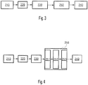
- an upsampling processing module 250 in the encoder as shown in fig. 3 , wherein the upsampling processing module is configured to subject the first processing signal to upsampling processing, such that the first processing signal (the sampling frequency of which is the first sampling rate) is converted to a second processing signal (the sampling frequency of which is a second sampling rate), wherein the second sampling rate is higher than the first sampling rate.
- the second processing signal is then sent to the electric machine driver by the communication module 230.
- the second processing signal at this time after the first processing signal has been processed to increase the sampling rate, has reduced the angular difference between two sampling points, and thereby greatly increased the accuracy of the sampling points, and in turn ameliorated problems such as abnormal spikes in the electric machine rotation speed signal calculated at the driver side, caused by the problem of clock asynchrony.
- the first processing signal is a 10 kHz (Hertz) sine wave input signal
- the first sampling rate is 400 kHz; this then corresponds to 40 sampling points in one period; in this case, if forward/rearward misplacement of sampling points occurs in a position information signal (i.e.
- the second angular difference is far smaller than the first angular difference, therefore the accuracy of the sampling points can be greatly increased, so as to ameliorate problems such as abnormal spikes in electric machine rotation speed signals calculated at the driver side, caused by the problem of clock asynchrony.
- Upsampling processing may be specifically implemented in different ways; for example, it may be subjecting the first processing signal to zero interpolation and interpolation filtering, to obtain the second processing signal. Alternatively, it could also be using a digital sampling module with a high sampling rate to perform digital sampling, to obtain the second processing signal.
- Fig. 4 is a schematic structural diagram of a capacitive encoder in an example of the present invention.
- an upsampling processing module 250 in the capacitive encoder may specifically comprise: a data cache sub-module 251, a zero interpolation sub-module 252 and an interpolation filtering sub-module 253.
- the data cache sub-module 251 is configured to receive and cache a first processing signal with a first sampling rate from the digital signal processing module 230.
- Fig. 5 shows schematic diagrams of a first processing signal x old (n) received by the data cache sub-module 251 in this example and a frequency spectrum X old (f) thereof. On the left is a schematic diagram of the first processing signal x old (n); on the right is a schematic diagram of the frequency spectrum X old (f) of the first processing signal x old (n).
- the sampling period is T s and the sampling frequency is f s .
- the zero interpolation sub-module 252 is configured to insert N-1 zeros uniformly between each pair of adjacent digital sampling points in the first processing signal, on the basis of a set interpolation factor N, to obtain an intermediate signal, the sampling frequency of which is a second sampling rate; the second sampling rate is N times the first sampling rate.
- N is a positive integer
- the maximum value of N is the ratio of the maximum value of a data frequency which can be outputted by the upsampling processing module 250, to the first sampling rate.
- sampling period T s,new T s /5
- sampling frequency f s,new 5f s , i.e. the sampling rate has been increased by a factor of 5.
- the interpolation filtering sub-module 253 is configured to subject the intermediate signal with the second sampling rate to interpolation filtering (e.g. processing which includes low-pass filtering), to filter out a high-frequency mirror image frequency spectrum, obtain a second processing signal (the sampling frequency of which is the second sampling rate), and provide the second processing signal to the communication module 240 as a signal to be sent.
- Fig. 7 shows schematic diagrams of a second processing signal x new (m) obtained by interpolation filtering in this example, and a frequency spectrum X new (f) thereof. On the left is a schematic diagram of the second processing signal x new (m); on the right is a schematic diagram of the frequency spectrum X new (f) of the second processing signal x new (m).
- the sampling rate has increased by a factor of 5.
- the lower-limit value of the interpolation factor is 1, and the upper-limit value is the ratio of the maximum value of a data frequency which can be outputted by the upsampling processing module 250, to the first sampling rate; for example, it could be another value, such as 10, 15, 20, 25, 30, etc.
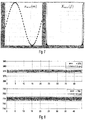
- Fig. 8 is a schematic performance diagram of electric machine rotation speed signals obtained through calculation at the electric machine driver side after receiving the second processing signal in said example.
- the x-axis is minutes and the y-axis is rpm (revolutions per minute).
- the electric machine rotation speed shown in the upper figure is 375 rpm; the electric machine rotation speed shown in the lower figure is 750 rpm.
- problems such as abnormal spikes caused by clock source asynchrony have been eliminated in both of the different electric machine rotation speed signals calculated.
- analog-to-digital conversion module 220, digital signal processing module 230, upsampling processing module 250 and communication module 240 may be implemented by means of software, or by means of hardware, or by means of a combination of software and hardware.
- the sub-modules in the upsampling processing module 250 may also be implemented by means of software, or by means of hardware, or by means of a combination of software and hardware.
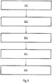
- Fig. 9 is a demonstrative flow chart of a signal processing method of a capacitive encoder in an embodiment of the present invention. As Fig. 9 shows, the method may comprise the following steps:
- Upsampling processing may be zero interpolation and interpolation filtering, or using a digital sampling module with a high sampling rate to obtain the second processing signal.
- this step 904 may comprise inserting N-1 zeros uniformly between each pair of adjacent digital sampling points in the first processing signal with the first sampling rate, on the basis of a set interpolation factor N, to obtain an intermediate signal with a second sampling rate; the second sampling rate is N times the first sampling rate.
- N is a positive integer, and N is less than the ratio of an operating frequency of the upsampling processing module 250, to a data frequency of the first processing signal.
- the intermediate signal with the second sampling rate is subjected to interpolation filtering, to filter out a high-frequency mirror image frequency spectrum, and obtain a second processing signal with the second sampling rate.
- the interpolation factor may be 1, 5, 6, 7, 8, 9, 10, ..., 15,..., 20,..., 25,..., 30,...
- the lower-limit value of the interpolation factor is 1, and the upper-limit value is the ratio of the maximum value of a data frequency which can be outputted by the upsampling processing module performing this step 904, to the first sampling rate.
- Step 905 sending the second processing signal with the second sampling rate to the electric machine driver.
- the present invention also provides a machine-readable storage medium, which stores instructions configured to cause a computer to perform all or a part of the signal processing method of a capacitive encoder as described herein.
- a system or apparatus equipped with a storage medium may be provided; software program code realizing functions of any one of the embodiments above is stored on the storage medium, and a computer (or CPU or MPU) of the system or apparatus is caused to read and execute program code stored in the storage medium.
- program code read from a storage medium can itself realize functions of any one of the embodiments above, hence the program code and the storage medium storing the program code form part of the present invention.
- Examples of storage media configured to provide program code include the cloud, floppy disks, hard disks, magneto-optical disks, optical disks (such as CD-ROM, CD-R, CD-RW, DVD-ROM, DVD-RAM, DVD-RW, DVD+RW), magnetic tapes, non-volatile memory cards, ROM, PC machines, mobile phones and various intelligent devices, etc.
- program code may be downloaded from a server computer via a communication network.
- an operating system operating on a computer can be made to complete a portion of or all actual operations, not only through execution of program code read by a computer, but also by means of instructions based on program code, so as to realize functions of any one of the embodiments above.
- program code read out from the storage medium is written into a memory installed in an expansion board inserted in the computer, or written into a memory installed in an expansion unit connected to the computer, and thereafter instructions based on the program code make a CPU etc. installed on the expansion board or expansion unit execute part or all of an actual operation, so as to realize the function of any one of the embodiments above.
Landscapes
- Physics & Mathematics (AREA)
- General Physics & Mathematics (AREA)
- Transmission And Conversion Of Sensor Element Output (AREA)
- Control Of Electric Motors In General (AREA)
Applications Claiming Priority (1)
| Application Number | Priority Date | Filing Date | Title |
|---|---|---|---|
| CN201710334893.7A CN108871385B (zh) | 2017-05-12 | 2017-05-12 | 编码器、电机、编码器数据处理方法及存储介质 |
Publications (2)
| Publication Number | Publication Date |
|---|---|
| EP3401643A1 true EP3401643A1 (de) | 2018-11-14 |
| EP3401643B1 EP3401643B1 (de) | 2020-09-02 |
Family
ID=59506059
Family Applications (1)
| Application Number | Title | Priority Date | Filing Date |
|---|---|---|---|
| EP17183000.3A Not-in-force EP3401643B1 (de) | 2017-05-12 | 2017-07-25 | Codierer, elektrische maschine, codiererdatenverarbeitungsverfahren und speichermedium |
Country Status (2)
| Country | Link |
|---|---|
| EP (1) | EP3401643B1 (de) |
| CN (1) | CN108871385B (de) |
Cited By (1)
| Publication number | Priority date | Publication date | Assignee | Title |
|---|---|---|---|---|
| CN119472479A (zh) * | 2025-01-15 | 2025-02-18 | 北京坤驰科技有限公司 | 一种状态监测的系统、方法、电子设备及存储介质 |
Families Citing this family (1)
| Publication number | Priority date | Publication date | Assignee | Title |
|---|---|---|---|---|
| CN114279481B (zh) * | 2021-11-25 | 2023-09-19 | 季华实验室 | 编码器转速波动性测试系统及方法 |
Citations (5)
| Publication number | Priority date | Publication date | Assignee | Title |
|---|---|---|---|---|
| EP1021698A1 (de) * | 1996-02-23 | 2000-07-26 | Monitoring Technology Corporation | Dynamischer ungleichmässiger takt für wiederabtestung und verarbeitung von maschinensignalen |
| WO2006077795A1 (ja) * | 2005-01-21 | 2006-07-27 | Pioneer Corporation | サンプリング周波数変換装置 |
| EP1874669A1 (de) * | 2005-03-08 | 2008-01-09 | Otis Elevator Company | Steuersystem zur steuerung der geschwindigkeit eines personenbeförderers |
| US20120146561A1 (en) * | 2009-08-17 | 2012-06-14 | Robert Bosch Gmbh | Electronically commutated electric motor featuring prediction of the rotor position and interpolation, and method |
| US20160033580A1 (en) * | 2012-05-29 | 2016-02-04 | Board Of Regents Of The University Of Nebraska | Detecting Faults in Turbine Generators |
Family Cites Families (18)
| Publication number | Priority date | Publication date | Assignee | Title |
|---|---|---|---|---|
| CN1150517C (zh) * | 2001-06-01 | 2004-05-19 | 华为技术有限公司 | 可实现阻抗匹配和混合平衡的语音编解码芯片 |
| CN100469068C (zh) * | 2005-01-28 | 2009-03-11 | 北京北广科数字广播电视技术有限公司 | 基于正交调制的用于数字广播(drm)的调相载波实现方法 |
| DE102006024742A1 (de) * | 2006-05-26 | 2007-12-06 | Siemens Ag | Messumformer |
| US20080122457A1 (en) * | 2006-11-28 | 2008-05-29 | Kabushiki Kaisha Toshiba | Capacitance difference detecting circuit |
| CN101639337B (zh) * | 2009-09-07 | 2011-04-27 | 北京航天控制仪器研究所 | 精密离心机动态半径和动态失准角的实时测量方法及装置 |
| CN102571657B (zh) * | 2010-12-10 | 2015-10-21 | 中兴通讯股份有限公司 | 一种变换采样率的数字预失真处理系统和方法 |
| CN102055479A (zh) * | 2010-12-29 | 2011-05-11 | 清华大学 | 一种优化功耗和输出信噪比的数模转换器 |
| CN102394714B (zh) * | 2011-08-06 | 2014-03-12 | 桂林市思奇通信设备有限公司 | 调频广播频段数字广播信号接收方法和接收系统 |
| CN102721395B (zh) * | 2012-07-09 | 2014-07-30 | 合肥工业大学 | 多尺寸凸轮轴相位角测量仪 |
| US8890634B2 (en) * | 2012-10-26 | 2014-11-18 | Mstar Semiconductor, Inc. | Multiplexed configurable sigma delta modulators for noise shaping in a 25-percent duty cycle digital transmitter |
| CN103791928B (zh) * | 2012-10-31 | 2016-04-13 | 西门子公司 | 电容编码器的读出电路及方法 |
| DE102013107120A1 (de) * | 2013-07-05 | 2015-01-08 | Endress + Hauser Gmbh + Co. Kg | Signalgenerator für eine Messvorrichtung und Messvorrichtung für die Automatisierungstechnik |
| EP3061252A1 (de) * | 2013-10-22 | 2016-08-31 | VID SCALE, Inc. | Fehlerverdeckungsmodus-signalisierung für ein videoübertragungssystem |
| CN103944575A (zh) * | 2014-04-21 | 2014-07-23 | 中国科学院半导体研究所 | 过采样64倍有效位数为18位的σ-δ调制电路 |
| EP2980792A1 (de) * | 2014-07-28 | 2016-02-03 | Fraunhofer-Gesellschaft zur Förderung der angewandten Forschung e.V. | Vorrichtung und Verfahren zur Erzeugung eines verbesserten Signals mit unabhängiger Rausch-Füllung |
| CN104539261B (zh) * | 2014-12-08 | 2017-08-29 | 北京遥测技术研究所 | 一种任意采样率转换的内插滤波处理方法 |
| US10175130B2 (en) * | 2015-04-20 | 2019-01-08 | Infineon Technologies Ag | System and method for a MEMS sensor |
| US11677967B2 (en) * | 2015-04-21 | 2023-06-13 | Arris Enterprises Llc | Scalable video coding system with parameter signaling |
-
2017
- 2017-05-12 CN CN201710334893.7A patent/CN108871385B/zh not_active Expired - Fee Related
- 2017-07-25 EP EP17183000.3A patent/EP3401643B1/de not_active Not-in-force
Patent Citations (5)
| Publication number | Priority date | Publication date | Assignee | Title |
|---|---|---|---|---|
| EP1021698A1 (de) * | 1996-02-23 | 2000-07-26 | Monitoring Technology Corporation | Dynamischer ungleichmässiger takt für wiederabtestung und verarbeitung von maschinensignalen |
| WO2006077795A1 (ja) * | 2005-01-21 | 2006-07-27 | Pioneer Corporation | サンプリング周波数変換装置 |
| EP1874669A1 (de) * | 2005-03-08 | 2008-01-09 | Otis Elevator Company | Steuersystem zur steuerung der geschwindigkeit eines personenbeförderers |
| US20120146561A1 (en) * | 2009-08-17 | 2012-06-14 | Robert Bosch Gmbh | Electronically commutated electric motor featuring prediction of the rotor position and interpolation, and method |
| US20160033580A1 (en) * | 2012-05-29 | 2016-02-04 | Board Of Regents Of The University Of Nebraska | Detecting Faults in Turbine Generators |
Cited By (1)
| Publication number | Priority date | Publication date | Assignee | Title |
|---|---|---|---|---|
| CN119472479A (zh) * | 2025-01-15 | 2025-02-18 | 北京坤驰科技有限公司 | 一种状态监测的系统、方法、电子设备及存储介质 |
Also Published As
| Publication number | Publication date |
|---|---|
| EP3401643B1 (de) | 2020-09-02 |
| CN108871385B (zh) | 2021-09-07 |
| CN108871385A (zh) | 2018-11-23 |
Similar Documents
| Publication | Publication Date | Title |
|---|---|---|
| CN111585682B (zh) | 传感器时间同步方法、装置及终端设备 | |
| CN107817502A (zh) | 激光点云数据处理方法和装置 | |
| CN111999555B (zh) | 伺服系统谐振频率检测方法、装置、电子设备及存储介质 | |
| CN102315927A (zh) | 一种时钟同步装置及方法 | |
| CN117705176B (zh) | 一种旋转角度脉冲校正方法、装置、设备和存储介质 | |
| EP3401643A1 (de) | Codierer, elektrische maschine, codiererdatenverarbeitungsverfahren und speichermedium | |
| CN115540742B (zh) | 电涡流传感器的低频误差信号抑制方法、装置、设备及介质 | |
| CN116222639B (zh) | 基于编码器的校正处理方法、装置、设备及介质 | |
| EP3496327B1 (de) | Verfahren zur erfassung eines phasendiskriminationssignals in einer taktrückgewinnungsschaltung und phasendiskriminator | |
| CN205384031U (zh) | 一种磁阻式旋转变压器的信号校正电路 | |
| EP3677873A1 (de) | Sofortkorrekturverfahren für einen codierer und system dafür | |
| CN111061330A (zh) | 一种变频器母线电压修正方法、装置、电子设备及存储介质 | |
| CN105526954A (zh) | 一种磁阻式旋转变压器的信号处理方法 | |
| CN117792193B (zh) | 正余弦包络线的提取方法、装置、电子设备及存储介质 | |
| CN118548923A (zh) | 用于计算旋转变压器差分相移的方法及装置、电路、电子设备 | |
| EP3642965B1 (de) | System-on-a-chip zum empfang von telemetrienachrichten über einen rundfunkkanal | |
| CN113691339B (zh) | 时钟同步方法、装置、设备及存储介质 | |
| CN116054821B (en) | Apparatus and method for recovering carrier signal | |
| CN109492185B (zh) | 一种采样数据处理方法及装置 | |
| CN113111542B (zh) | 一种基于s函数的卡尔曼滤波的频率跟踪方法及系统 | |
| CN115542807B (zh) | 一种基于fpga确定电角度的方法、装置及介质 | |
| CN114786251B (zh) | 一种5g小区同步方法、装置、电子设备及存储介质 | |
| CN121309820B (zh) | 一种码率估计装置及方法、视频编码器、电子设备、存储介质和计算机程序产品 | |
| CN121323696B (zh) | 编码器位置检测方法、装置、设备及介质 | |
| CN117516901A (zh) | 用于基于惯导技术的风机叶片监测的时钟同步方法与系统 |
Legal Events
| Date | Code | Title | Description |
|---|---|---|---|
| PUAI | Public reference made under article 153(3) epc to a published international application that has entered the european phase |
Free format text: ORIGINAL CODE: 0009012 |
|
| STAA | Information on the status of an ep patent application or granted ep patent |
Free format text: STATUS: THE APPLICATION HAS BEEN PUBLISHED |
|
| AK | Designated contracting states |
Kind code of ref document: A1 Designated state(s): AL AT BE BG CH CY CZ DE DK EE ES FI FR GB GR HR HU IE IS IT LI LT LU LV MC MK MT NL NO PL PT RO RS SE SI SK SM TR |
|
| AX | Request for extension of the european patent |
Extension state: BA ME |
|
| STAA | Information on the status of an ep patent application or granted ep patent |
Free format text: STATUS: REQUEST FOR EXAMINATION WAS MADE |
|
| 17P | Request for examination filed |
Effective date: 20190514 |
|
| RBV | Designated contracting states (corrected) |
Designated state(s): AL AT BE BG CH CY CZ DE DK EE ES FI FR GB GR HR HU IE IS IT LI LT LU LV MC MK MT NL NO PL PT RO RS SE SI SK SM TR |
|
| GRAP | Despatch of communication of intention to grant a patent |
Free format text: ORIGINAL CODE: EPIDOSNIGR1 |
|
| STAA | Information on the status of an ep patent application or granted ep patent |
Free format text: STATUS: GRANT OF PATENT IS INTENDED |
|
| INTG | Intention to grant announced |
Effective date: 20200507 |
|
| GRAS | Grant fee paid |
Free format text: ORIGINAL CODE: EPIDOSNIGR3 |
|
| GRAA | (expected) grant |
Free format text: ORIGINAL CODE: 0009210 |
|
| STAA | Information on the status of an ep patent application or granted ep patent |
Free format text: STATUS: THE PATENT HAS BEEN GRANTED |
|
| AK | Designated contracting states |
Kind code of ref document: B1 Designated state(s): AL AT BE BG CH CY CZ DE DK EE ES FI FR GB GR HR HU IE IS IT LI LT LU LV MC MK MT NL NO PL PT RO RS SE SI SK SM TR |
|
| REG | Reference to a national code |
Ref country code: GB Ref legal event code: FG4D |
|
| REG | Reference to a national code |
Ref country code: AT Ref legal event code: REF Ref document number: 1309359 Country of ref document: AT Kind code of ref document: T Effective date: 20200915 Ref country code: CH Ref legal event code: EP |
|
| REG | Reference to a national code |
Ref country code: DE Ref legal event code: R096 Ref document number: 602017022665 Country of ref document: DE |
|
| REG | Reference to a national code |
Ref country code: IE Ref legal event code: FG4D |
|
| REG | Reference to a national code |
Ref country code: LT Ref legal event code: MG4D |
|
| PG25 | Lapsed in a contracting state [announced via postgrant information from national office to epo] |
Ref country code: BG Free format text: LAPSE BECAUSE OF FAILURE TO SUBMIT A TRANSLATION OF THE DESCRIPTION OR TO PAY THE FEE WITHIN THE PRESCRIBED TIME-LIMIT Effective date: 20201202 Ref country code: HR Free format text: LAPSE BECAUSE OF FAILURE TO SUBMIT A TRANSLATION OF THE DESCRIPTION OR TO PAY THE FEE WITHIN THE PRESCRIBED TIME-LIMIT Effective date: 20200902 Ref country code: LT Free format text: LAPSE BECAUSE OF FAILURE TO SUBMIT A TRANSLATION OF THE DESCRIPTION OR TO PAY THE FEE WITHIN THE PRESCRIBED TIME-LIMIT Effective date: 20200902 Ref country code: NO Free format text: LAPSE BECAUSE OF FAILURE TO SUBMIT A TRANSLATION OF THE DESCRIPTION OR TO PAY THE FEE WITHIN THE PRESCRIBED TIME-LIMIT Effective date: 20201202 Ref country code: FI Free format text: LAPSE BECAUSE OF FAILURE TO SUBMIT A TRANSLATION OF THE DESCRIPTION OR TO PAY THE FEE WITHIN THE PRESCRIBED TIME-LIMIT Effective date: 20200902 Ref country code: GR Free format text: LAPSE BECAUSE OF FAILURE TO SUBMIT A TRANSLATION OF THE DESCRIPTION OR TO PAY THE FEE WITHIN THE PRESCRIBED TIME-LIMIT Effective date: 20201203 Ref country code: SE Free format text: LAPSE BECAUSE OF FAILURE TO SUBMIT A TRANSLATION OF THE DESCRIPTION OR TO PAY THE FEE WITHIN THE PRESCRIBED TIME-LIMIT Effective date: 20200902 |
|
| REG | Reference to a national code |
Ref country code: NL Ref legal event code: MP Effective date: 20200902 |
|
| REG | Reference to a national code |
Ref country code: AT Ref legal event code: MK05 Ref document number: 1309359 Country of ref document: AT Kind code of ref document: T Effective date: 20200902 |
|
| PG25 | Lapsed in a contracting state [announced via postgrant information from national office to epo] |
Ref country code: RS Free format text: LAPSE BECAUSE OF FAILURE TO SUBMIT A TRANSLATION OF THE DESCRIPTION OR TO PAY THE FEE WITHIN THE PRESCRIBED TIME-LIMIT Effective date: 20200902 Ref country code: PL Free format text: LAPSE BECAUSE OF FAILURE TO SUBMIT A TRANSLATION OF THE DESCRIPTION OR TO PAY THE FEE WITHIN THE PRESCRIBED TIME-LIMIT Effective date: 20200902 Ref country code: LV Free format text: LAPSE BECAUSE OF FAILURE TO SUBMIT A TRANSLATION OF THE DESCRIPTION OR TO PAY THE FEE WITHIN THE PRESCRIBED TIME-LIMIT Effective date: 20200902 |
|
| PG25 | Lapsed in a contracting state [announced via postgrant information from national office to epo] |
Ref country code: CZ Free format text: LAPSE BECAUSE OF FAILURE TO SUBMIT A TRANSLATION OF THE DESCRIPTION OR TO PAY THE FEE WITHIN THE PRESCRIBED TIME-LIMIT Effective date: 20200902 Ref country code: RO Free format text: LAPSE BECAUSE OF FAILURE TO SUBMIT A TRANSLATION OF THE DESCRIPTION OR TO PAY THE FEE WITHIN THE PRESCRIBED TIME-LIMIT Effective date: 20200902 Ref country code: PT Free format text: LAPSE BECAUSE OF FAILURE TO SUBMIT A TRANSLATION OF THE DESCRIPTION OR TO PAY THE FEE WITHIN THE PRESCRIBED TIME-LIMIT Effective date: 20210104 Ref country code: EE Free format text: LAPSE BECAUSE OF FAILURE TO SUBMIT A TRANSLATION OF THE DESCRIPTION OR TO PAY THE FEE WITHIN THE PRESCRIBED TIME-LIMIT Effective date: 20200902 Ref country code: SM Free format text: LAPSE BECAUSE OF FAILURE TO SUBMIT A TRANSLATION OF THE DESCRIPTION OR TO PAY THE FEE WITHIN THE PRESCRIBED TIME-LIMIT Effective date: 20200902 |
|
| PG25 | Lapsed in a contracting state [announced via postgrant information from national office to epo] |
Ref country code: AL Free format text: LAPSE BECAUSE OF FAILURE TO SUBMIT A TRANSLATION OF THE DESCRIPTION OR TO PAY THE FEE WITHIN THE PRESCRIBED TIME-LIMIT Effective date: 20200902 Ref country code: AT Free format text: LAPSE BECAUSE OF FAILURE TO SUBMIT A TRANSLATION OF THE DESCRIPTION OR TO PAY THE FEE WITHIN THE PRESCRIBED TIME-LIMIT Effective date: 20200902 Ref country code: ES Free format text: LAPSE BECAUSE OF FAILURE TO SUBMIT A TRANSLATION OF THE DESCRIPTION OR TO PAY THE FEE WITHIN THE PRESCRIBED TIME-LIMIT Effective date: 20200902 Ref country code: IS Free format text: LAPSE BECAUSE OF FAILURE TO SUBMIT A TRANSLATION OF THE DESCRIPTION OR TO PAY THE FEE WITHIN THE PRESCRIBED TIME-LIMIT Effective date: 20210102 |
|
| REG | Reference to a national code |
Ref country code: DE Ref legal event code: R097 Ref document number: 602017022665 Country of ref document: DE |
|
| PG25 | Lapsed in a contracting state [announced via postgrant information from national office to epo] |
Ref country code: SK Free format text: LAPSE BECAUSE OF FAILURE TO SUBMIT A TRANSLATION OF THE DESCRIPTION OR TO PAY THE FEE WITHIN THE PRESCRIBED TIME-LIMIT Effective date: 20200902 |
|
| PLBE | No opposition filed within time limit |
Free format text: ORIGINAL CODE: 0009261 |
|
| STAA | Information on the status of an ep patent application or granted ep patent |
Free format text: STATUS: NO OPPOSITION FILED WITHIN TIME LIMIT |
|
| 26N | No opposition filed |
Effective date: 20210603 |
|
| PG25 | Lapsed in a contracting state [announced via postgrant information from national office to epo] |
Ref country code: DK Free format text: LAPSE BECAUSE OF FAILURE TO SUBMIT A TRANSLATION OF THE DESCRIPTION OR TO PAY THE FEE WITHIN THE PRESCRIBED TIME-LIMIT Effective date: 20200902 Ref country code: SI Free format text: LAPSE BECAUSE OF FAILURE TO SUBMIT A TRANSLATION OF THE DESCRIPTION OR TO PAY THE FEE WITHIN THE PRESCRIBED TIME-LIMIT Effective date: 20200902 |
|
| PG25 | Lapsed in a contracting state [announced via postgrant information from national office to epo] |
Ref country code: IT Free format text: LAPSE BECAUSE OF FAILURE TO SUBMIT A TRANSLATION OF THE DESCRIPTION OR TO PAY THE FEE WITHIN THE PRESCRIBED TIME-LIMIT Effective date: 20200902 |
|
| REG | Reference to a national code |
Ref country code: CH Ref legal event code: PL |
|
| PG25 | Lapsed in a contracting state [announced via postgrant information from national office to epo] |
Ref country code: MC Free format text: LAPSE BECAUSE OF FAILURE TO SUBMIT A TRANSLATION OF THE DESCRIPTION OR TO PAY THE FEE WITHIN THE PRESCRIBED TIME-LIMIT Effective date: 20200902 |
|
| REG | Reference to a national code |
Ref country code: BE Ref legal event code: MM Effective date: 20210731 |
|
| PG25 | Lapsed in a contracting state [announced via postgrant information from national office to epo] |
Ref country code: LI Free format text: LAPSE BECAUSE OF NON-PAYMENT OF DUE FEES Effective date: 20210731 Ref country code: CH Free format text: LAPSE BECAUSE OF NON-PAYMENT OF DUE FEES Effective date: 20210731 |
|
| PG25 | Lapsed in a contracting state [announced via postgrant information from national office to epo] |
Ref country code: LU Free format text: LAPSE BECAUSE OF NON-PAYMENT OF DUE FEES Effective date: 20210725 |
|
| PG25 | Lapsed in a contracting state [announced via postgrant information from national office to epo] |
Ref country code: IE Free format text: LAPSE BECAUSE OF NON-PAYMENT OF DUE FEES Effective date: 20210725 Ref country code: BE Free format text: LAPSE BECAUSE OF NON-PAYMENT OF DUE FEES Effective date: 20210731 |
|
| P01 | Opt-out of the competence of the unified patent court (upc) registered |
Effective date: 20230510 |
|
| PG25 | Lapsed in a contracting state [announced via postgrant information from national office to epo] |
Ref country code: NL Free format text: LAPSE BECAUSE OF NON-PAYMENT OF DUE FEES Effective date: 20200923 Ref country code: CY Free format text: LAPSE BECAUSE OF FAILURE TO SUBMIT A TRANSLATION OF THE DESCRIPTION OR TO PAY THE FEE WITHIN THE PRESCRIBED TIME-LIMIT Effective date: 20200902 |
|
| PG25 | Lapsed in a contracting state [announced via postgrant information from national office to epo] |
Ref country code: HU Free format text: LAPSE BECAUSE OF FAILURE TO SUBMIT A TRANSLATION OF THE DESCRIPTION OR TO PAY THE FEE WITHIN THE PRESCRIBED TIME-LIMIT; INVALID AB INITIO Effective date: 20170725 |
|
| PGFP | Annual fee paid to national office [announced via postgrant information from national office to epo] |
Ref country code: GB Payment date: 20230807 Year of fee payment: 7 |
|
| PGFP | Annual fee paid to national office [announced via postgrant information from national office to epo] |
Ref country code: FR Payment date: 20230720 Year of fee payment: 7 Ref country code: DE Payment date: 20230918 Year of fee payment: 7 |
|
| PG25 | Lapsed in a contracting state [announced via postgrant information from national office to epo] |
Ref country code: MK Free format text: LAPSE BECAUSE OF FAILURE TO SUBMIT A TRANSLATION OF THE DESCRIPTION OR TO PAY THE FEE WITHIN THE PRESCRIBED TIME-LIMIT Effective date: 20200902 |
|
| PG25 | Lapsed in a contracting state [announced via postgrant information from national office to epo] |
Ref country code: MT Free format text: LAPSE BECAUSE OF FAILURE TO SUBMIT A TRANSLATION OF THE DESCRIPTION OR TO PAY THE FEE WITHIN THE PRESCRIBED TIME-LIMIT Effective date: 20200902 |
|
| REG | Reference to a national code |
Ref country code: DE Ref legal event code: R119 Ref document number: 602017022665 Country of ref document: DE |
|
| GBPC | Gb: european patent ceased through non-payment of renewal fee |
Effective date: 20240725 |
|
| PG25 | Lapsed in a contracting state [announced via postgrant information from national office to epo] |
Ref country code: DE Free format text: LAPSE BECAUSE OF NON-PAYMENT OF DUE FEES Effective date: 20250201 |
|
| PG25 | Lapsed in a contracting state [announced via postgrant information from national office to epo] |
Ref country code: FR Free format text: LAPSE BECAUSE OF NON-PAYMENT OF DUE FEES Effective date: 20240731 |
|
| PG25 | Lapsed in a contracting state [announced via postgrant information from national office to epo] |
Ref country code: GB Free format text: LAPSE BECAUSE OF NON-PAYMENT OF DUE FEES Effective date: 20240725 |
|
| PG25 | Lapsed in a contracting state [announced via postgrant information from national office to epo] |
Ref country code: TR Free format text: LAPSE BECAUSE OF FAILURE TO SUBMIT A TRANSLATION OF THE DESCRIPTION OR TO PAY THE FEE WITHIN THE PRESCRIBED TIME-LIMIT Effective date: 20200902 |