EP3401651B1 - Mesure de niveau, mesure de pression ou mesure de débit à temps de mesure court - Google Patents
Mesure de niveau, mesure de pression ou mesure de débit à temps de mesure court Download PDFInfo
- Publication number
- EP3401651B1 EP3401651B1 EP17170169.1A EP17170169A EP3401651B1 EP 3401651 B1 EP3401651 B1 EP 3401651B1 EP 17170169 A EP17170169 A EP 17170169A EP 3401651 B1 EP3401651 B1 EP 3401651B1
- Authority
- EP
- European Patent Office
- Prior art keywords
- processor
- circuit
- analog
- buffer
- measurement
- Prior art date
- Legal status (The legal status is an assumption and is not a legal conclusion. Google has not performed a legal analysis and makes no representation as to the accuracy of the status listed.)
- Active
Links
Images



Classifications
-
- G—PHYSICS
- G01—MEASURING; TESTING
- G01F—MEASURING VOLUME, VOLUME FLOW, MASS FLOW OR LIQUID LEVEL; METERING BY VOLUME
- G01F23/00—Indicating or measuring liquid level or level of fluent solid material, e.g. indicating in terms of volume or indicating by means of an alarm
- G01F23/22—Indicating or measuring liquid level or level of fluent solid material, e.g. indicating in terms of volume or indicating by means of an alarm by measuring physical variables, other than linear dimensions, pressure or weight, dependent on the level to be measured, e.g. by difference of heat transfer of steam or water
- G01F23/28—Indicating or measuring liquid level or level of fluent solid material, e.g. indicating in terms of volume or indicating by means of an alarm by measuring physical variables, other than linear dimensions, pressure or weight, dependent on the level to be measured, e.g. by difference of heat transfer of steam or water by measuring the variations of parameters of electromagnetic or acoustic waves applied directly to the liquid or fluent solid material
- G01F23/284—Electromagnetic waves
-
- G—PHYSICS
- G01—MEASURING; TESTING
- G01F—MEASURING VOLUME, VOLUME FLOW, MASS FLOW OR LIQUID LEVEL; METERING BY VOLUME
- G01F23/00—Indicating or measuring liquid level or level of fluent solid material, e.g. indicating in terms of volume or indicating by means of an alarm
- G01F23/80—Arrangements for signal processing
- G01F23/802—Particular electronic circuits for digital processing equipment
-
- G—PHYSICS
- G01—MEASURING; TESTING
- G01L—MEASURING FORCE, STRESS, TORQUE, WORK, MECHANICAL POWER, MECHANICAL EFFICIENCY, OR FLUID PRESSURE
- G01L9/00—Measuring steady of quasi-steady pressure of fluid or fluent solid material by electric or magnetic pressure-sensitive elements; Transmitting or indicating the displacement of mechanical pressure-sensitive elements, used to measure the steady or quasi-steady pressure of a fluid or fluent solid material, by electric or magnetic means
-
- H—ELECTRICITY
- H01—ELECTRIC ELEMENTS
- H01Q—ANTENNAS, i.e. RADIO AERIALS
- H01Q1/00—Details of, or arrangements associated with, antennas
- H01Q1/12—Supports; Mounting means
- H01Q1/22—Supports; Mounting means by structural association with other equipment or articles
- H01Q1/225—Supports; Mounting means by structural association with other equipment or articles used in level-measurement devices, e.g. for level gauge measurement
-
- G—PHYSICS
- G01—MEASURING; TESTING
- G01F—MEASURING VOLUME, VOLUME FLOW, MASS FLOW OR LIQUID LEVEL; METERING BY VOLUME
- G01F23/00—Indicating or measuring liquid level or level of fluent solid material, e.g. indicating in terms of volume or indicating by means of an alarm
- G01F23/80—Arrangements for signal processing
- G01F23/802—Particular electronic circuits for digital processing equipment
- G01F23/804—Particular electronic circuits for digital processing equipment containing circuits handling parameters other than liquid level
Definitions
- the invention relates to measuring devices for industrial process automation.
- the invention relates to a level radar, a measuring device circuit for a measuring device, a method for acquiring and processing measurement data from a measuring device, a program element and a computer-readable medium.
- Radar devices for level measurement are often based on the frequency modulated continuous wave method, which is also known as FMCW (Frequency Modulated Continuous Wave). These systems are usually supplied with energy via a two-wire line, which means that the operation of microwave modules with a high power requirement can only be implemented using sophisticated energy management and power-saving circuit components.
- FMCW Frequency Modulated Continuous Wave
- An essential system parameter when designing FMCW systems is the time period T, during which the system transmits a microwave signal in the direction of the product surface radiates.
- T time period
- all high-frequency components, all analog signal processing components and also the analog/digital converter must be supplied with energy.
- the energy consumed per measurement cycle is therefore directly related to the specification of the time period T and can be reduced by reducing the measurement time.
- U.S. 7,334,470 B1 describes a filling level measuring system for pulsed operation, which has a resampling stage.
- WO 03/019120 A1 describes a method and a device for the direct digitization of microwave signals.
- the microwave signals reflected on the surface of the filling material can be stored in an analog storage unit with an unchanged frequency at a first sampling rate.
- the stored analog values are then converted into digital values at a second rate, which is lower than the first rate, and by means of an A/D converter, which can now have a relatively low sampling rate due to the intermediate storage.
- a first aspect of the invention relates to a filling level radar with a processor and an analog/digital converter circuit. Between the analog-to-digital converter circuit and the processor, there is a buffer module that connects these two units to one another.
- the buffer memory module is used to receive digital signals from the analog/digital converter circuit at a first data rate.
- the processor is designed to read out the intermediate memory module at a second data rate, which is lower than the first data rate.
- the first data rate is higher or even significantly higher than the second data rate. This makes it possible to use slower, energy-saving processors.
- the analog-to-digital converter circuit is designed to generate the digital signals in the form of a differential output signal.
- the analog/digital converter circuit has what is known as a low-voltage differential signaling interface, LVDS.
- the processor is connected to the intermediate storage module via an asymmetrical communication line, whereas the analog/digital converter circuit is connected to the intermediate storage module via a symmetrical communication or data transmission line.
- the intermediate memory module is a programmable logic module, in particular an FPGA module (FPGA: Field Programmable Gate Array) in combination with a data memory.
- FPGA Field Programmable Gate Array
- the digital signals that are output by the analog/digital converter circuit from the buffer module can be the digital samples of the received signal of the level radar (or more generally: of the measuring device).
- the received signal is typically the transmission signal of the filling level radar reflected by the filling material surface and other reflectors.
- the buffer memory module can be set up to process the received digital signals from the analog/digital converter circuit.
- provision can be made for the buffer memory module to derive a measured value or calculates several measured values or pre-processes the signal so that the downstream processor can calculate the measured value with less effort.
- the buffer memory module has a first-in, first-out memory and/or a ring memory.
- the measuring device circuit and in particular the level radar is designed for connection to a 4-20mA two-wire loop for power supply of the measuring device and for outputting the measured values as well as for further communication with an external control device.
- the measuring device circuit relates to a measuring device, which is a filling level measuring device, a limit level measuring device, a pressure measuring device or a flow measuring device.
- the measuring device has a processor, an analog/digital converter circuit and a buffer module. These elements correspond to the elements of the level radar described above.
- the features described above and below can also be implemented in other measuring device circuits.
- the features described below with regard to the method can be implemented by the elements of the measuring device circuits and various level radar systems.
- the features described below with regard to the filling level radar can be implemented as method steps.
- a further aspect of the invention relates to a method for level measurement, pressure measurement or flow measurement and for acquiring and processing measurement data from a measuring device
- Process automation such as a level gauge, a pressure gauge, a point level sensor or a flow meter.
- digital signals are received in the buffer memory module.
- the digital signals correspond to recorded measurement data, for example a transmission signal received by the device and reflected on the surface of the filling material, from an analog/digital converter circuit at a first data rate.
- the intermediate memory module is read out by the processor at a second data rate which is not equal to the first data rate. According to the invention, the second data rate is lower than the first data rate.
- the measured value is output by the measuring device and this measured value was calculated from the digital signals and the measured value is output by the processor.
- the measured value can be calculated in the processor, or in the intermediate memory module, or in cooperation between the processor and the intermediate memory module. Thereafter, the processor is put into a sleep mode in order to save energy, after which the buffer memory module can be activated again.
- a further aspect of the invention relates to a program element which, when executed on a measuring device circuit, which is described above and below, instructs the measuring device circuit to carry out the method steps described above and below.
- a further aspect of the invention relates to a computer-readable medium on which the program element described above is stored.
- a further aspect of the invention relates to the use of a measuring device circuit, as described above and below, for the level measurement.
- a further aspect of the invention relates to the use of such a measuring device circuit for pressure measurement and a further aspect of the invention relates to the use of such a measuring device circuit for flow measurement.
- the analog-to-digital converter circuit has a relatively high operating frequency and it can be provided that it differentially transmits the digital data to the buffer store.
- the buffer memory module which can be digitally programmed, for example, serves as a converter between the fast differential output signals of the analog/digital converter circuit and the typically asymmetrical signal inputs of the energy-saving processor.
- An important aspect of the invention is that at least one processor and at least one analog-to-digital converter circuit and at least one intermediate memory module are provided, the intermediate memory module receiving digital samples from the at least one analog-to-digital converter circuit at a first data rate, and the Processor reads digital samples from the buffer device at a second data rate, the first data rate being unequal to the second data rate.
- an energy-saving measuring device circuit for example for a level measuring device, which has at least one analog-to-digital converter circuit with a differential output signal, at least one processor with at least one asymmetric input and at least one mediator module which is connected to the processor via at least one unbalanced communication line and to the analog-to-digital converter circuit with at least one balanced data transmission line.
- the intermediary module is the buffer module mentioned above.
- the deactivation of the analog-to-digital converter circuit can be triggered by the energy available to the measuring device falling below a predetermined measured value. This is intended to prevent the measuring device running into an energy deficit, i.e. only having insufficient energy available to carry out the intended tasks.
- the analog-to-digital converter circuit 601 is deactivated if the intermediate storage module threatens to “fill up”. This means that the buffer memory only has a very limited amount of free memory available and it is foreseeable that this free memory capacity will be used up in the foreseeable future.
- a threshold value can be defined, which defines how much free minimum memory must be available in the buffer memory module so that the analog/digital converter circuit can remain active.
- This threshold value can be defined, for example, as a function of the first data rate at which the analog/digital converter sends its signals to the buffer memory module and/or the amount of data to be transmitted per measurement cycle. Since these variables can be changed as a function of the measurement task and the parameterization of the measuring device, provision can be made for the measuring device to be able to adapt the abovementioned threshold values independently.
- the sensor front end and the intermediate storage unit are always deactivated simultaneously, or one after the other: the sensor front end is deactivated first and later, when it has completed its tasks, the intermediate storage unit. Provision can be made for this activation to always take place after a measurement cycle has been carried out. Depending on the amount of energy available, however, it can also be provided that several Measurement cycles are carried out before this deactivation takes place. Provision can also be made for the processor to be activated only when a measurement cycle has ended in order to read out the buffer storage unit. If sufficient energy is available, however, provision can also be made for the processor to be activated at an earlier point in time and to read out the digitized data from the intermediate storage unit.
- the front end Only when the available energy falls below a predetermined threshold value is the front end first deactivated and possibly at the same time or shortly thereafter the buffer storage unit.
- the measurement cycle is interrupted by a state with the processor, buffer, analog-to-digital converter unit and front end deactivated. If a predefined amount of energy is present, the measuring system then switches back to a state with an activated processor and activated buffer unit.
- the processor has finished reading the buffer unit and deactivates the buffer unit again.
- the processor determines at least one measured value and outputs it. This is then also deactivated so that energy can be collected again.
- FIG. 1 shows essential components of a radar fill level measuring device 101, which is also referred to as a fill level radar in the context of the invention.
- Modern radar level gauges are used in a variety of ways in all areas of industry. In recent years, there has been a transition to ever higher working frequencies, which allow the antennas of such innovative radar measuring devices to be further reduced in terms of their geometric size.
- the level gauge 1 is supplied with energy via a supply line 102 .
- the use of 4..20mA technology is widespread at this point, which enables the measured value determined by the measuring device to be read out on the basis of the supply current taken up.
- the worst-case scenario results in a power of 48mW, with which the entire measuring device 101 must be operated.
- the measuring device 101 has a power supply unit 103, which generally also has components for energy management, for example an energy store.
- the power supply unit 103 is connected to a processor 104, which is designed to control the sensor sequence, evaluate the signals and manage energy in interaction with the other components of the measuring device.
- the measuring device also has a high-frequency unit 106 which emits high-frequency signals in the range of 6 GHz, 24 GHz, 79 GHz or higher frequencies via a transmitter and/or receiver unit 107 in the direction of a filling material surface.
- the high-frequency unit 106 receives the signal components reflected by the filling material and/or container installations and converts them into an analog, low-frequency intermediate-frequency signal using known methods.
- An analog/digital converter unit 105 also referred to as an analog/digital converter circuit in the context of the invention, converts these analog intermediate frequency signals into digital signals and forwards them via a suitable interface to the processor 104 for further evaluation.
- the high-frequency unit 106 can achieve the conversion of the high-frequency signals into low-frequency intermediate-frequency signals, for example, by pulse modulation in conjunction with a time expansion method. Provision can also be made to modulate the radiated high-frequency signals in relation to the respective frequency and to achieve conversion into low-frequency intermediate-frequency signals according to the FMCW principle.
- the level measuring device continuously emits high-frequency signals 108 in the direction of a filling material surface.
- the width of the echoes detected by the measuring device depends directly on the bandwidth ⁇ f 202, which is why the largest possible frequency deviation f2 - f1 should be aimed for for small measuring vessels in order to be able to reliably separate echoes that are very close together.
- the high-frequency unit determines the difference between the frequency 301 of the transmitted signal and the frequency 302 of the received signal.
- the intermediate frequency signals are digitized with high accuracy (typically 16 bits).
- frequencies 304 in the range of 0-213 kHz result here for measurement distances of up to 40 m.
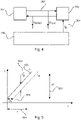
- processors Taking into account the Nyquist theorem, samples with a sampling frequency of up to 500 kHz are typically used as analog-to-digital converters. The acquired data must be transmitted to a processor 104 in real time during the measurement. Since the criterion of energy efficiency plays a paramount role when selecting a suitable processor 104, these processors generally do not have any high-speed interfaces, but instead support common asymmetric IO standards such as SPI (Serial Peripheral Interface) or IIC (Inter-Integrated Circuit).
- SPI Serial Peripheral Interface
- IIC Inter-Integrated Circuit
- FIG. 4 shows an example of data transmission via SPI.
- Available A/D converters with operating frequencies greater than 1 GHz therefore mostly have differential or symmetrical outputs in order to be able to reliably implement the high data rates during analog-to-digital conversion in terms of circuitry.
- figure 5 shows a measuring sequence of a level measuring device optimized for small containers according to the FMCW method. Compared to the operating mode of the figure 3 was developed with a view to faster determination of measured values and a reduction in energy consumption High-frequency elements massively reduces the measurement time T 501. Here, for example, measurement times of a few hundred microseconds are aimed at.
- the bandwidth ⁇ f 502 has been increased in order to be able to better separate echoes that are close together.
- Each of the measures described contributes to the fact that the intermediate frequency signals 503 provided by the high-frequency unit 106 in relation to their respective frequency compared to the operating mode of the figure 3 are greatly increased.
- intermediate frequency signals with a frequency of 1.4 MHz already result for echoes at a distance of 2m.
- fast analog-to-digital converters with high clock frequencies are of fundamental importance for the intended optimization of the radar measuring devices.
- such converters generally have to be connected to a processor via a differential digital interface.
- Corresponding processors with such an input interface are unsuitable for use in level measuring devices with regard to the required power.
- An A/D converter 601 with a high sampling rate is used to convert the intermediate frequency signals 503 .
- the A/D converter 601 has a differential interface suitable for high clock rates, for example an LVDS interface. Since the actual signal processing and/or control processor 104 cannot read in differential signals at high speed, a programmable logic device 602 is used as an intermediate element.
- the logic module 602 is factory programmed to read the data from the A/D converter into a FIFO memory 602 in real time.
- the processor 104 can access the programmable logic module 602 and here in particular the FIFO memory within the programmable logic module via an asymmetric interface, for example an SPI interface, and can read data from it.
- the FIFO memory within the programmable logic module 602 can be set up to temporarily store the digital data of the A/D converter for a complete measurement cycle 501 . Provision can also be made for the FIFO memory to be in the form of a ring memory with a smaller size, and to make use of the fact that the processor 104 can already read out part of the digital samples from the FIFO memory during the measurement.
- the programmable logic modules used can have sufficient energy management functions, which make use in a two-wire radar fill level measuring device possible.
- an operating sequence can be implemented that further improves the energy-efficient use of programmable logic components in the signal detection branch.
- FIG. 7 shows a first flow chart for the operation of a measuring device according to an embodiment of the invention.
- the method begins in the starting state 701, in which all the components are in a deactivated, ie in an energy-saving, operating state.
- energy is collected.
- the high-frequency unit 106, the A/D converter 601 and the programmable logic module 602 are switched to a regular operating mode.
- step 705 according to the scheme of figure 5 a measurement performed.
- the measured values recorded in this way are neglected to a certain Throughput time almost synchronously transferred to the memory of the programmable logic module 602.
- step 706 the high-frequency unit 106 and the analog/digital converter unit 601 are immediately deactivated again, ie transferred to an energy-saving state.
- step 707 the processor 104 is awakened from its SLEEP mode in order to read the digital measurement data from the programmable logic device 602 in step 708 .
- step 709 the logic module 602 is deactivated, whereupon in step 710 the processor 104 determines the measured value according to known methods.
- the measured value is provided to the outside, for example in the form of a loop current within line 102.
- step 712 the processor is switched back to an energy-saving mode, and the method continues with the step of energy collection 702.
- FIG 8 Figure 12 illustrates a method according to another embodiment of the invention.
- the method begins in the initial state 801, in which the components 104, 601, 602, 106 are deactivated, ie are in an energy-saving state.
- the power supply unit 103 first collects energy, for example in a capacitor within the unit 103.
- the programmable logic module 602 the analog-to-digital converter unit 601 and the Radio frequency unit 106 activated.
- step 805 one or more echo curves are recorded according to a known method by the transmission of one or more transmitter ramps 301, 504 and are converted into digital samples by the analog/digital converter unit 601.
- the digital sampled values are transmitted essentially synchronously over a symmetrical signal transmission line 603 to the programmable logic module 602 and stored there.
- step 806 both the high-frequency unit 106 and the analog-to-digital converter unit 601 disabled to save power.
- step 807 it is checked whether there is sufficient energy to start the signal processing within the programmable logic module 602 . If this is not the case, in step 808 energy is first collected. Provision can be made here for the programmable logic module to be switched to an energy-saving state in which the memory contents with the measured values are retained.
- step 809 the actual processing of the signals in the programmable logic module 602 begins. Since heavily parallelized algorithms, for example filtering or fast Fourier transformations, are usually used for this, a significant amount of calculation time can be saved by mapping these method steps in specialized hardware blocks within the unit 602, which can reduce the energy consumption of the sensor. Provision can also be made here for realizing part of the signal processing by procedural software logic within a soft core processor in module 602 . In step 810 at least one or more measured values are provided within module 602 .
- step 811 the processor unit 104, which is also referred to as a processor in the context of the invention, is activated, and in step 812 the at least one measured value is transmitted via at least one asymmetric signal connection 604. It should be pointed out here that the amount of data to be transmitted is very small here, which is why very slow transmission standards can be used here.
- step 813 the programmable logic module is deactivated again before in step 814 the at least one measured value is made available to the outside, for example by the energy supply unit 103 .
- step 815 the processor 104 is switched back to an energy-saving state.
- the processor unit 104 can also be part of the energy supply unit 103 . It may also be provided that the processor unit 104 and the programmable logic unit 602 within one to realize chips. In the latter case, the asymmetrical transmission of data is made possible by direct access to memory locations using an internal bus system within a logic module 602 that has been programmed accordingly. It should also be pointed out that the analog/digital converter unit 601 and the high-frequency unit 106 can also be accommodated in a common chip and/or chip housing.
- the present invention can be used advantageously in connection with energy-saving two-wire sensors for level measurement.
- the scope of the present invention can also be used with so-called four-wire sensors.
- the invention can also be used to a particular degree for so-called multi-channel radar systems, for example for determining the topology of a bulk material surface.
- the programmable logic unit 602 can be implemented in a further embodiment by a functionally identical, application-specific circuit (ASIC).
- ASIC application-specific circuit
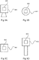
- Figure 9A 12 shows a level radar 900 with a measuring device circuit 600 according to an embodiment of the invention.
- the measuring device can be designed for three-dimensional filling level measurement, in which the topology of the filling material surface can be determined by scanning the surface.
- the measuring device can be set up to record data surrounding the vehicle.
- Figure 9B shows a pressure gauge 901 with a gauge circuit 600.
- Figure 9C shows a flow meter 902 with a meter circuit 600 and
- Figure 9D shows a point level sensor 903 with a measuring device circuit 600.
Landscapes
- Physics & Mathematics (AREA)
- Electromagnetism (AREA)
- General Physics & Mathematics (AREA)
- Fluid Mechanics (AREA)
- Engineering & Computer Science (AREA)
- Signal Processing (AREA)
- Thermal Sciences (AREA)
- Radar Systems Or Details Thereof (AREA)
- Details Of Flowmeters (AREA)
- Measurement Of Levels Of Liquids Or Fluent Solid Materials (AREA)
- Measuring Fluid Pressure (AREA)
Claims (13)
- Procédé de mesure de niveau de remplissage, de mesure de niveau limite, de mesure de pression ou de mesure de débit et d'acquisition et de traitement de données de mesure, comprenant les étapes consistant à :activer un processeur (104);activer un module de mémoire tampon (602) ;recevoir des signaux numériques correspondant à des données de mesure acquises, provenant d'un circuit de conversion analogique-numérique (601), à un premier débit de données dans le module de mémoire tampon ;lire le module de mémoire tampon à un deuxième débit de données, qui est inférieur au premier débit de données, par le processeur (104) ;désactiver le module de mémoire tampon ;délivrer, par le processeur, une valeur de mesure qui a été calculée par le processeur et/ou le module de mémoire tampon à partir des signaux numériques;mettre le processeur (104) en veille.
- Radar de niveau de remplissage, configuré pour mettre en œuvre un procédé selon la revendication 1, présentant :au moins le processeur (104) ;au moins le circuit de conversion analogique-numérique (601) ;au moins le module de mémoire tampon (602) disposé entre le processeur et le circuit de conversion analogique-numérique ;dans lequel le module de mémoire tampon est conçu pour recevoir des signaux numériques du circuit de conversion analogique-numérique au premier débit de données ;dans lequel le processeur est conçu pour lire le module de mémoire tampon au deuxième débit de données qui est inférieur au premier débit de données.
- Radar de niveau de remplissage selon la revendication 2,
dans lequel le circuit de conversion analogique-numérique (601) présente une interface différentielle et est conçu pour générer les signaux numériques sous la forme d'un signal de sortie différentiel. - Radar de niveau de remplissage selon l'une des revendications 2 à 3 précédentes,
dans lequel le module de mémoire tampon (602) présente un module logique programmable. - Radar de niveau de remplissage selon l'une des revendications 2 à 4 précédentes,
dans lequel les signaux numériques sont des valeurs d'échantillonnage numériques d'un signal de réception du radar de niveau de remplissage. - Radar de niveau de remplissage selon l'une des revendications 2 à 5 précédentes,
dans lequel le module de mémoire tampon (602) est conçu pour traiter les signaux numériques reçus. - Radar de niveau de remplissage selon l'une des revendications 2 à 6,
dans lequel le module de mémoire tampon (602) présente une mémoire premier entré, premier sorti et/ou une mémoire circulaire. - Radar de niveau de remplissage selon l'une des revendications 2 à 7 précédentes,
conçu pour être connecté à une interface bifilaire 4-20 mA pour l'alimentation en énergie et la sortie des valeurs de mesure. - Élément de programme qui, lorsqu'il est exécuté sur un circuit d'appareil de mesure, amène le circuit d'appareil de mesure à exécuter les étapes selon la revendication 1.
- Support lisible par ordinateur sur lequel est stocké un élément de programme selon la revendication 9.
- Utilisation d'un circuit d'appareil de mesure (600), configuré pour mettre en œuvre un procédé selon la revendication 1, pour la mesure de niveau limite, le circuit d'appareil de mesure présentant :au moins le processeur (104) ;au moins le circuit de conversion analogique-numérique (601) ;au moins le module de mémoire tampon (602) disposé entre le processeur et le circuit de conversion analogique-numérique ;dans lequel le module de mémoire tampon est conçu pour recevoir des signaux numériques du circuit de conversion analogique-numérique au premier débit de données ;dans lequel le processeur est conçu pour lire le module de mémoire tampon au deuxième débit de données qui est inférieur au premier débit de données.
- Utilisation d'un circuit d'appareil de mesure (600), configuré pour mettre en œuvre un procédé selon la revendication 1, pour la mesure de pression, le circuit d'appareil de mesure présentant :au moins le processeur (104) ;au moins le circuit de conversion analogique-numérique (601) ;au moins le module de mémoire tampon (602) disposé entre le processeur et le circuit de conversion analogique-numérique ;dans lequel le module de mémoire tampon est conçu pour recevoir des signaux numériques du circuit de conversion analogique-numérique au premier débit de données ;dans lequel le processeur est conçu pour lire le module de mémoire tampon audeuxième débit de données qui est inférieur au premier débit de données.
- Utilisation d'un circuit d'appareil de mesure (600), configuré pour mettre en œuvre un procédé selon la revendication 1, pour la mesure de débit, le circuit d'appareil de mesure présentant :au moins le processeur (104) ;au moins le circuit de conversion analogique-numérique (601) ;au moins le module de mémoire tampon (602) disposé entre le processeur et le circuit de conversion analogique-numérique ;dans lequel le module de mémoire tampon est conçu pour recevoir des signaux numériques du circuit de conversion analogique-numérique au premier débit de données ;dans lequel le processeur est conçu pour lire le module de mémoire tampon au deuxième débit de données qui est inférieur au premier débit de données.
Priority Applications (8)
| Application Number | Priority Date | Filing Date | Title |
|---|---|---|---|
| HUE17170169A HUE060006T2 (hu) | 2017-05-09 | 2017-05-09 | Határszint mérés, nyomásmérés vagy áramlásmérés rövid mérési idõvel |
| ES17170169T ES2927288T3 (es) | 2017-05-09 | 2017-05-09 | Medición de nivel límite, medición de presión o medición de caudal con tiempo de medición corto |
| HRP20221145TT HRP20221145T1 (hr) | 2017-05-09 | 2017-05-09 | Mjerenje razine punjenja, mjerenje tlaka ili mjerenje protoka s kratkim vremenom mjerenja |
| EP17170169.1A EP3401651B1 (fr) | 2017-05-09 | 2017-05-09 | Mesure de niveau, mesure de pression ou mesure de débit à temps de mesure court |
| CN201810408499.8A CN109029633B (zh) | 2017-05-09 | 2018-05-02 | 具有短测量时间的填充物位雷达 |
| DE102018207164.0A DE102018207164A1 (de) | 2017-05-09 | 2018-05-08 | Füllstandradar mit kurzer Messzeit |
| US15/974,437 US10948333B2 (en) | 2017-05-09 | 2018-05-08 | Radar level indicator having a short measurement time |
| DE202018006710.5U DE202018006710U1 (de) | 2017-05-09 | 2018-05-08 | Füllstandradar mit kurzer Messzeit |
Applications Claiming Priority (1)
| Application Number | Priority Date | Filing Date | Title |
|---|---|---|---|
| EP17170169.1A EP3401651B1 (fr) | 2017-05-09 | 2017-05-09 | Mesure de niveau, mesure de pression ou mesure de débit à temps de mesure court |
Publications (2)
| Publication Number | Publication Date |
|---|---|
| EP3401651A1 EP3401651A1 (fr) | 2018-11-14 |
| EP3401651B1 true EP3401651B1 (fr) | 2022-07-13 |
Family
ID=58699010
Family Applications (1)
| Application Number | Title | Priority Date | Filing Date |
|---|---|---|---|
| EP17170169.1A Active EP3401651B1 (fr) | 2017-05-09 | 2017-05-09 | Mesure de niveau, mesure de pression ou mesure de débit à temps de mesure court |
Country Status (7)
| Country | Link |
|---|---|
| US (1) | US10948333B2 (fr) |
| EP (1) | EP3401651B1 (fr) |
| CN (1) | CN109029633B (fr) |
| DE (2) | DE202018006710U1 (fr) |
| ES (1) | ES2927288T3 (fr) |
| HR (1) | HRP20221145T1 (fr) |
| HU (1) | HUE060006T2 (fr) |
Families Citing this family (12)
| Publication number | Priority date | Publication date | Assignee | Title |
|---|---|---|---|---|
| EP3692343B1 (fr) | 2017-10-06 | 2022-10-05 | VEGA Grieshaber KG | Jauge de niveau avec système radar |
| US11841424B2 (en) * | 2017-11-28 | 2023-12-12 | Texas Instruments Incorporated | Methods and electronic device for dynamic distance measurements |
| EP3696817B1 (fr) * | 2019-02-18 | 2022-03-30 | VEGA Grieshaber KG | Capteur radar doté d'une interface de communication |
| EP4168755A1 (fr) * | 2020-06-18 | 2023-04-26 | VEGA Grieshaber KG | Radar de niveau de remplissage pour capture de niveau et de topologie |
| CN115917267A (zh) | 2020-07-20 | 2023-04-04 | Vega格里沙贝两合公司 | 自给式多维测量雷达传感器 |
| CN115867771A (zh) * | 2020-07-20 | 2023-03-28 | Vega格里沙贝两合公司 | 多维测量物位雷达和方法 |
| HUE063341T2 (hu) | 2021-06-07 | 2024-01-28 | Grieshaber Vega Kg | Szintradar változtatható kvantálási pontossággal |
| DE102021128370A1 (de) | 2021-10-29 | 2023-05-04 | Vega Grieshaber Kg | Druckmesszelle mit Auswerteelektronik und 4-20 mA Schnittstelle |
| DE102021133933A1 (de) | 2021-12-20 | 2023-06-22 | Endress+Hauser Flowtec Ag | Signal-Übertragungssystem |
| DE102023105489A1 (de) | 2022-12-30 | 2024-07-11 | Endress + Hauser Flowtec Ag | Sende-/Empfangsschaltung sowie damit gebildetes Signal-Übertragungssystem |
| CN120391045A (zh) | 2022-12-30 | 2025-07-29 | 恩德斯豪斯流量技术股份有限公司 | 发射/接收电路以及由其形成的信号传输系统 |
| CN121359007A (zh) * | 2023-09-22 | 2026-01-16 | 爱适瑞卫生健康产品有限公司 | 用于卫生消耗品的自主料位传感器 |
Citations (8)
| Publication number | Priority date | Publication date | Assignee | Title |
|---|---|---|---|---|
| US5072220A (en) * | 1990-02-14 | 1991-12-10 | Siemens Aktiengesellschaft | Analog/digital converter operating by the expanded parallel method |
| WO2003019120A1 (fr) * | 2001-08-20 | 2003-03-06 | Vega Grieshaber Kg | Procede et dispositif pour numeriser directement des signaux hyperfrequences |
| US20070186678A1 (en) * | 2006-02-13 | 2007-08-16 | Karl Griessbaum | Paired ZF Sampling for Pulse Running Time Filling Level Sensor |
| US20120201100A1 (en) * | 2011-01-11 | 2012-08-09 | Siemens Aktiengesellschaft | Method for Echo Processing in a Pulse-Echo Ranging System |
| EP2677285A2 (fr) * | 2012-06-18 | 2013-12-25 | Rosemount Tank Radar AB | Détermination du niveau de remplissage intermittent avec nombre de mesures déterminé de façon dynamique |
| US20140002274A1 (en) * | 2012-06-29 | 2014-01-02 | Rosemount Tank Radar Ab | Battery-powered level gauge system adapted for wireless communication |
| US8843329B2 (en) * | 2009-03-02 | 2014-09-23 | Vega Grieshaber Kg | Measuring filling level by means of evaluating an echo curve |
| US20170076711A1 (en) * | 2015-09-15 | 2017-03-16 | Harman Becker Automotive Systems Gmbh | Wireless noise and vibration sensing |
Family Cites Families (17)
| Publication number | Priority date | Publication date | Assignee | Title |
|---|---|---|---|---|
| US5245347A (en) * | 1980-12-29 | 1993-09-14 | Raytheon Company | All weather tactical strike system (AWTSS) and method of operation |
| US6581460B1 (en) * | 2002-01-28 | 2003-06-24 | Vega Grieshaber Kg | Method and device for direct digitizing microwave signals |
| DE102004022911B4 (de) * | 2004-05-10 | 2012-03-01 | Sick Ag | Signalabtastung |
| US7333900B2 (en) * | 2004-08-16 | 2008-02-19 | Vega Grieshaber Kg | Automatic parasitic echo storage |
| US7334470B1 (en) * | 2004-09-30 | 2008-02-26 | Siemens Milltronics Process Instruments, Inc. | Digital interface and receiver for time-of-flight level measurement and pulse-echo ranging systems |
| CN1282866C (zh) * | 2004-12-23 | 2006-11-01 | 太原理工大学 | 数字化雷达物位计 |
| US7683780B2 (en) * | 2006-07-24 | 2010-03-23 | Thingmagic, Inc. | Methods and apparatus for RFID tag placement |
| CN100472572C (zh) * | 2007-06-26 | 2009-03-25 | 北京必创科技有限公司 | 一种实现低功耗无线监测的装置 |
| CN101350036B (zh) * | 2008-08-26 | 2010-09-15 | 天津理工大学 | 一种高速实时数据采集系统 |
| EP2369362A1 (fr) * | 2010-03-18 | 2011-09-28 | Siemens Milltronics Process Instruments Inc. | Récepteur pour système de télémétrie par impulsion-écho avec filtre numérique à décimation polyphase |
| CN201707145U (zh) * | 2010-06-18 | 2011-01-12 | 陈瑞杰 | 基于无线传感网的高精度热电偶无线温度传感器 |
| CN102121994B (zh) * | 2010-12-20 | 2014-08-06 | 西安华朗物探科技有限公司 | 一种高分辨率石油地震勘探系统的数据采集板 |
| CN102339324A (zh) * | 2011-09-15 | 2012-02-01 | 中国电力科学研究院 | 一种基于硬件实现的高速数据采集卡 |
| CN102661773B (zh) * | 2012-05-15 | 2013-09-11 | 合肥工业大学 | 一种处理导波式雷达物位计回波信号的系统和方法 |
| CN202838339U (zh) * | 2012-07-11 | 2013-03-27 | 南京国电环保科技有限公司 | 基于dsp和fpga的高速数据采集处理系统 |
| CN103259649A (zh) * | 2013-05-09 | 2013-08-21 | 成都秦川科技发展有限公司 | 嵌有信息安全管理模块的远控智能热能表 |
| CN104006865A (zh) * | 2014-06-11 | 2014-08-27 | 中国科学院电子学研究所 | 雷达液位测量数据处理系统 |
-
2017
- 2017-05-09 HR HRP20221145TT patent/HRP20221145T1/hr unknown
- 2017-05-09 EP EP17170169.1A patent/EP3401651B1/fr active Active
- 2017-05-09 ES ES17170169T patent/ES2927288T3/es active Active
- 2017-05-09 HU HUE17170169A patent/HUE060006T2/hu unknown
-
2018
- 2018-05-02 CN CN201810408499.8A patent/CN109029633B/zh active Active
- 2018-05-08 US US15/974,437 patent/US10948333B2/en active Active
- 2018-05-08 DE DE202018006710.5U patent/DE202018006710U1/de active Active
- 2018-05-08 DE DE102018207164.0A patent/DE102018207164A1/de active Pending
Patent Citations (8)
| Publication number | Priority date | Publication date | Assignee | Title |
|---|---|---|---|---|
| US5072220A (en) * | 1990-02-14 | 1991-12-10 | Siemens Aktiengesellschaft | Analog/digital converter operating by the expanded parallel method |
| WO2003019120A1 (fr) * | 2001-08-20 | 2003-03-06 | Vega Grieshaber Kg | Procede et dispositif pour numeriser directement des signaux hyperfrequences |
| US20070186678A1 (en) * | 2006-02-13 | 2007-08-16 | Karl Griessbaum | Paired ZF Sampling for Pulse Running Time Filling Level Sensor |
| US8843329B2 (en) * | 2009-03-02 | 2014-09-23 | Vega Grieshaber Kg | Measuring filling level by means of evaluating an echo curve |
| US20120201100A1 (en) * | 2011-01-11 | 2012-08-09 | Siemens Aktiengesellschaft | Method for Echo Processing in a Pulse-Echo Ranging System |
| EP2677285A2 (fr) * | 2012-06-18 | 2013-12-25 | Rosemount Tank Radar AB | Détermination du niveau de remplissage intermittent avec nombre de mesures déterminé de façon dynamique |
| US20140002274A1 (en) * | 2012-06-29 | 2014-01-02 | Rosemount Tank Radar Ab | Battery-powered level gauge system adapted for wireless communication |
| US20170076711A1 (en) * | 2015-09-15 | 2017-03-16 | Harman Becker Automotive Systems Gmbh | Wireless noise and vibration sensing |
Also Published As
| Publication number | Publication date |
|---|---|
| DE202018006710U1 (de) | 2022-04-07 |
| ES2927288T3 (es) | 2022-11-03 |
| DE102018207164A1 (de) | 2018-11-15 |
| US10948333B2 (en) | 2021-03-16 |
| HUE060006T2 (hu) | 2023-01-28 |
| EP3401651A1 (fr) | 2018-11-14 |
| HRP20221145T1 (hr) | 2022-11-25 |
| US20180328774A1 (en) | 2018-11-15 |
| CN109029633B (zh) | 2022-05-24 |
| CN109029633A (zh) | 2018-12-18 |
Similar Documents
| Publication | Publication Date | Title |
|---|---|---|
| EP3401651B1 (fr) | Mesure de niveau, mesure de pression ou mesure de débit à temps de mesure court | |
| EP3418700B1 (fr) | Appareil de radiodétection de niveau de remplissage à adaptation automatique de la fréquence | |
| DE69730416T2 (de) | Füllstandmessradargerät | |
| DE10196024B3 (de) | Erfassung sich in unmittelbarer Nähe befindender Materialgrenzflächen für einen Mikrowellen-Niveausender | |
| EP3467450B1 (fr) | Appareil de mesure de niveau de remplissage à radar pourvu d'un système radar sur puce | |
| EP1210567B1 (fr) | Dispositif permettant de déterminer le niveau de remplissage d'un milieu | |
| WO2011076478A2 (fr) | Procédé de détermination et de surveillance du niveau de remplissage d'un contenant, renfermant un fluide, selon un procédé de mesure du temps de propagation | |
| DE102006062606A1 (de) | Verfahren zur Ermittlung und Überwachung des Füllstands eines Mediums in einem Behälter nach einem Laufzeitverfahren | |
| EP2626676B1 (fr) | Dispositif et procédé de correction d'un décalage | |
| DE102016108594B3 (de) | Verfahren zur Ermittlung des Füllstandes sowie zur Ermittlung zumindest einer Zusatzinformation | |
| DE102012107146A1 (de) | Verfahren zur Bestimmung und/oder Überwachung des Füllstands eines Mediums in einem Behälter | |
| DE112005001498T5 (de) | Radarfüllstandsmesssystem mit intermittierender Verstärkung | |
| WO2013092099A1 (fr) | Procédé et appareil pour mesurer le niveau de remplissage | |
| DE102017210402A1 (de) | Füllstandradargerät mit automatisierter frequenzanpassung | |
| WO2020069813A1 (fr) | Procédé de mesure du niveau de remplissage | |
| DE202017007519U1 (de) | Füllstandradar mit kurzer Messzeit | |
| EP4102194B1 (fr) | Radar de niveau de remplissage à précision de quantification changeante | |
| EP1315337B1 (fr) | Interface du bus | |
| WO2019149513A1 (fr) | Procédé de détection d'états d'erreur potentiels sur un dispositif de mesure de remplissage à base de fmcw | |
| EP3695197B1 (fr) | Procédé de détermination du niveau de remplissage d'un produit contenu dans un récipient | |
| DE102021103543A1 (de) | Winkelauflösendes Füllstandsmessgerät | |
| WO2007077079A1 (fr) | Procedes de determination et de controle du niveau de remplissage d'un fluide dans un contenant selon le principe de la duree de parcours | |
| EP4487091A1 (fr) | Compteur de niveau de remplissage | |
| EP1470395A2 (fr) | Procede et dispositif de numerisation directe de signaux micro-ondes | |
| DE102022105195A1 (de) | Füllstandsmessgerät |
Legal Events
| Date | Code | Title | Description |
|---|---|---|---|
| REG | Reference to a national code |
Ref country code: HR Ref legal event code: TUEP Ref document number: P20221145 Country of ref document: HR Ref country code: DE Ref legal event code: R138 Ref document number: 202017007519 Country of ref document: DE Free format text: GERMAN DOCUMENT NUMBER IS 502017013448 |
|
| PUAI | Public reference made under article 153(3) epc to a published international application that has entered the european phase |
Free format text: ORIGINAL CODE: 0009012 |
|
| STAA | Information on the status of an ep patent application or granted ep patent |
Free format text: STATUS: THE APPLICATION HAS BEEN PUBLISHED |
|
| AK | Designated contracting states |
Kind code of ref document: A1 Designated state(s): AL AT BE BG CH CY CZ DE DK EE ES FI FR GB GR HR HU IE IS IT LI LT LU LV MC MK MT NL NO PL PT RO RS SE SI SK SM TR |
|
| AX | Request for extension of the european patent |
Extension state: BA ME |
|
| STAA | Information on the status of an ep patent application or granted ep patent |
Free format text: STATUS: REQUEST FOR EXAMINATION WAS MADE |
|
| 17P | Request for examination filed |
Effective date: 20190122 |
|
| RBV | Designated contracting states (corrected) |
Designated state(s): AL AT BE BG CH CY CZ DE DK EE ES FI FR GB GR HR HU IE IS IT LI LT LU LV MC MK MT NL NO PL PT RO RS SE SI SK SM TR |
|
| STAA | Information on the status of an ep patent application or granted ep patent |
Free format text: STATUS: EXAMINATION IS IN PROGRESS |
|
| 17Q | First examination report despatched |
Effective date: 20201112 |
|
| GRAP | Despatch of communication of intention to grant a patent |
Free format text: ORIGINAL CODE: EPIDOSNIGR1 |
|
| STAA | Information on the status of an ep patent application or granted ep patent |
Free format text: STATUS: GRANT OF PATENT IS INTENDED |
|
| INTG | Intention to grant announced |
Effective date: 20211208 |
|
| GRAJ | Information related to disapproval of communication of intention to grant by the applicant or resumption of examination proceedings by the epo deleted |
Free format text: ORIGINAL CODE: EPIDOSDIGR1 |
|
| STAA | Information on the status of an ep patent application or granted ep patent |
Free format text: STATUS: EXAMINATION IS IN PROGRESS |
|
| REG | Reference to a national code |
Ref country code: DE Ref legal event code: R079 Ref document number: 502017013448 Country of ref document: DE Free format text: PREVIOUS MAIN CLASS: G01F0023000000 Ipc: G01F0023800000 |
|
| INTC | Intention to grant announced (deleted) | ||
| GRAP | Despatch of communication of intention to grant a patent |
Free format text: ORIGINAL CODE: EPIDOSNIGR1 |
|
| STAA | Information on the status of an ep patent application or granted ep patent |
Free format text: STATUS: GRANT OF PATENT IS INTENDED |
|
| RIC1 | Information provided on ipc code assigned before grant |
Ipc: G01F 23/284 20060101ALI20220331BHEP Ipc: G01F 23/80 20220101AFI20220331BHEP |
|
| INTG | Intention to grant announced |
Effective date: 20220425 |
|
| GRAS | Grant fee paid |
Free format text: ORIGINAL CODE: EPIDOSNIGR3 |
|
| GRAA | (expected) grant |
Free format text: ORIGINAL CODE: 0009210 |
|
| STAA | Information on the status of an ep patent application or granted ep patent |
Free format text: STATUS: THE PATENT HAS BEEN GRANTED |
|
| AK | Designated contracting states |
Kind code of ref document: B1 Designated state(s): AL AT BE BG CH CY CZ DE DK EE ES FI FR GB GR HR HU IE IS IT LI LT LU LV MC MK MT NL NO PL PT RO RS SE SI SK SM TR |
|
| REG | Reference to a national code |
Ref country code: CH Ref legal event code: EP |
|
| REG | Reference to a national code |
Ref country code: DE Ref legal event code: R096 Ref document number: 502017013448 Country of ref document: DE |
|
| REG | Reference to a national code |
Ref country code: AT Ref legal event code: REF Ref document number: 1504502 Country of ref document: AT Kind code of ref document: T Effective date: 20220815 |
|
| REG | Reference to a national code |
Ref country code: IE Ref legal event code: FG4D Free format text: LANGUAGE OF EP DOCUMENT: GERMAN |
|
| REG | Reference to a national code |
Ref country code: SE Ref legal event code: TRGR |
|
| REG | Reference to a national code |
Ref country code: NL Ref legal event code: FP |
|
| REG | Reference to a national code |
Ref country code: ES Ref legal event code: FG2A Ref document number: 2927288 Country of ref document: ES Kind code of ref document: T3 Effective date: 20221103 |
|
| REG | Reference to a national code |
Ref country code: LT Ref legal event code: MG9D |
|
| REG | Reference to a national code |
Ref country code: HR Ref legal event code: T1PR Ref document number: P20221145 Country of ref document: HR |
|
| REG | Reference to a national code |
Ref country code: HU Ref legal event code: AG4A Ref document number: E060006 Country of ref document: HU |
|
| PG25 | Lapsed in a contracting state [announced via postgrant information from national office to epo] |
Ref country code: RS Free format text: LAPSE BECAUSE OF FAILURE TO SUBMIT A TRANSLATION OF THE DESCRIPTION OR TO PAY THE FEE WITHIN THE PRESCRIBED TIME-LIMIT Effective date: 20220713 Ref country code: PT Free format text: LAPSE BECAUSE OF FAILURE TO SUBMIT A TRANSLATION OF THE DESCRIPTION OR TO PAY THE FEE WITHIN THE PRESCRIBED TIME-LIMIT Effective date: 20221114 Ref country code: NO Free format text: LAPSE BECAUSE OF FAILURE TO SUBMIT A TRANSLATION OF THE DESCRIPTION OR TO PAY THE FEE WITHIN THE PRESCRIBED TIME-LIMIT Effective date: 20221013 Ref country code: LV Free format text: LAPSE BECAUSE OF FAILURE TO SUBMIT A TRANSLATION OF THE DESCRIPTION OR TO PAY THE FEE WITHIN THE PRESCRIBED TIME-LIMIT Effective date: 20220713 Ref country code: LT Free format text: LAPSE BECAUSE OF FAILURE TO SUBMIT A TRANSLATION OF THE DESCRIPTION OR TO PAY THE FEE WITHIN THE PRESCRIBED TIME-LIMIT Effective date: 20220713 Ref country code: FI Free format text: LAPSE BECAUSE OF FAILURE TO SUBMIT A TRANSLATION OF THE DESCRIPTION OR TO PAY THE FEE WITHIN THE PRESCRIBED TIME-LIMIT Effective date: 20220713 |
|
| PG25 | Lapsed in a contracting state [announced via postgrant information from national office to epo] |
Ref country code: PL Free format text: LAPSE BECAUSE OF FAILURE TO SUBMIT A TRANSLATION OF THE DESCRIPTION OR TO PAY THE FEE WITHIN THE PRESCRIBED TIME-LIMIT Effective date: 20220713 Ref country code: IS Free format text: LAPSE BECAUSE OF FAILURE TO SUBMIT A TRANSLATION OF THE DESCRIPTION OR TO PAY THE FEE WITHIN THE PRESCRIBED TIME-LIMIT Effective date: 20221113 Ref country code: GR Free format text: LAPSE BECAUSE OF FAILURE TO SUBMIT A TRANSLATION OF THE DESCRIPTION OR TO PAY THE FEE WITHIN THE PRESCRIBED TIME-LIMIT Effective date: 20221014 |
|
| REG | Reference to a national code |
Ref country code: DE Ref legal event code: R097 Ref document number: 502017013448 Country of ref document: DE |
|
| PG25 | Lapsed in a contracting state [announced via postgrant information from national office to epo] |
Ref country code: SM Free format text: LAPSE BECAUSE OF FAILURE TO SUBMIT A TRANSLATION OF THE DESCRIPTION OR TO PAY THE FEE WITHIN THE PRESCRIBED TIME-LIMIT Effective date: 20220713 Ref country code: RO Free format text: LAPSE BECAUSE OF FAILURE TO SUBMIT A TRANSLATION OF THE DESCRIPTION OR TO PAY THE FEE WITHIN THE PRESCRIBED TIME-LIMIT Effective date: 20220713 Ref country code: DK Free format text: LAPSE BECAUSE OF FAILURE TO SUBMIT A TRANSLATION OF THE DESCRIPTION OR TO PAY THE FEE WITHIN THE PRESCRIBED TIME-LIMIT Effective date: 20220713 Ref country code: CZ Free format text: LAPSE BECAUSE OF FAILURE TO SUBMIT A TRANSLATION OF THE DESCRIPTION OR TO PAY THE FEE WITHIN THE PRESCRIBED TIME-LIMIT Effective date: 20220713 |
|
| PLBE | No opposition filed within time limit |
Free format text: ORIGINAL CODE: 0009261 |
|
| STAA | Information on the status of an ep patent application or granted ep patent |
Free format text: STATUS: NO OPPOSITION FILED WITHIN TIME LIMIT |
|
| REG | Reference to a national code |
Ref country code: HR Ref legal event code: ODRP Ref document number: P20221145 Country of ref document: HR Payment date: 20230505 Year of fee payment: 7 |
|
| PG25 | Lapsed in a contracting state [announced via postgrant information from national office to epo] |
Ref country code: SK Free format text: LAPSE BECAUSE OF FAILURE TO SUBMIT A TRANSLATION OF THE DESCRIPTION OR TO PAY THE FEE WITHIN THE PRESCRIBED TIME-LIMIT Effective date: 20220713 Ref country code: EE Free format text: LAPSE BECAUSE OF FAILURE TO SUBMIT A TRANSLATION OF THE DESCRIPTION OR TO PAY THE FEE WITHIN THE PRESCRIBED TIME-LIMIT Effective date: 20220713 |
|
| P01 | Opt-out of the competence of the unified patent court (upc) registered |
Effective date: 20230508 |
|
| 26N | No opposition filed |
Effective date: 20230414 |
|
| PG25 | Lapsed in a contracting state [announced via postgrant information from national office to epo] |
Ref country code: AL Free format text: LAPSE BECAUSE OF FAILURE TO SUBMIT A TRANSLATION OF THE DESCRIPTION OR TO PAY THE FEE WITHIN THE PRESCRIBED TIME-LIMIT Effective date: 20220713 |
|
| PG25 | Lapsed in a contracting state [announced via postgrant information from national office to epo] |
Ref country code: SI Free format text: LAPSE BECAUSE OF FAILURE TO SUBMIT A TRANSLATION OF THE DESCRIPTION OR TO PAY THE FEE WITHIN THE PRESCRIBED TIME-LIMIT Effective date: 20220713 |
|
| REG | Reference to a national code |
Ref country code: CH Ref legal event code: PL |
|
| PG25 | Lapsed in a contracting state [announced via postgrant information from national office to epo] |
Ref country code: MC Free format text: LAPSE BECAUSE OF FAILURE TO SUBMIT A TRANSLATION OF THE DESCRIPTION OR TO PAY THE FEE WITHIN THE PRESCRIBED TIME-LIMIT Effective date: 20220713 |
|
| REG | Reference to a national code |
Ref country code: BE Ref legal event code: MM Effective date: 20230531 |
|
| PG25 | Lapsed in a contracting state [announced via postgrant information from national office to epo] |
Ref country code: MC Free format text: LAPSE BECAUSE OF FAILURE TO SUBMIT A TRANSLATION OF THE DESCRIPTION OR TO PAY THE FEE WITHIN THE PRESCRIBED TIME-LIMIT Effective date: 20220713 Ref country code: LU Free format text: LAPSE BECAUSE OF NON-PAYMENT OF DUE FEES Effective date: 20230509 Ref country code: LI Free format text: LAPSE BECAUSE OF NON-PAYMENT OF DUE FEES Effective date: 20230531 Ref country code: CH Free format text: LAPSE BECAUSE OF NON-PAYMENT OF DUE FEES Effective date: 20230531 |
|
| REG | Reference to a national code |
Ref country code: IE Ref legal event code: MM4A |
|
| PG25 | Lapsed in a contracting state [announced via postgrant information from national office to epo] |
Ref country code: IE Free format text: LAPSE BECAUSE OF NON-PAYMENT OF DUE FEES Effective date: 20230509 |
|
| PG25 | Lapsed in a contracting state [announced via postgrant information from national office to epo] |
Ref country code: IE Free format text: LAPSE BECAUSE OF NON-PAYMENT OF DUE FEES Effective date: 20230509 |
|
| REG | Reference to a national code |
Ref country code: HR Ref legal event code: ODRP Ref document number: P20221145 Country of ref document: HR Payment date: 20240503 Year of fee payment: 8 |
|
| PG25 | Lapsed in a contracting state [announced via postgrant information from national office to epo] |
Ref country code: BE Free format text: LAPSE BECAUSE OF NON-PAYMENT OF DUE FEES Effective date: 20230531 |
|
| REG | Reference to a national code |
Ref country code: AT Ref legal event code: MM01 Ref document number: 1504502 Country of ref document: AT Kind code of ref document: T Effective date: 20230509 |
|
| PG25 | Lapsed in a contracting state [announced via postgrant information from national office to epo] |
Ref country code: AT Free format text: LAPSE BECAUSE OF NON-PAYMENT OF DUE FEES Effective date: 20230509 |
|
| PG25 | Lapsed in a contracting state [announced via postgrant information from national office to epo] |
Ref country code: AT Free format text: LAPSE BECAUSE OF NON-PAYMENT OF DUE FEES Effective date: 20230509 |
|
| PG25 | Lapsed in a contracting state [announced via postgrant information from national office to epo] |
Ref country code: BG Free format text: LAPSE BECAUSE OF FAILURE TO SUBMIT A TRANSLATION OF THE DESCRIPTION OR TO PAY THE FEE WITHIN THE PRESCRIBED TIME-LIMIT Effective date: 20220713 |
|
| PG25 | Lapsed in a contracting state [announced via postgrant information from national office to epo] |
Ref country code: BG Free format text: LAPSE BECAUSE OF FAILURE TO SUBMIT A TRANSLATION OF THE DESCRIPTION OR TO PAY THE FEE WITHIN THE PRESCRIBED TIME-LIMIT Effective date: 20220713 |
|
| REG | Reference to a national code |
Ref country code: HR Ref legal event code: ODRP Ref document number: P20221145 Country of ref document: HR Payment date: 20250429 Year of fee payment: 9 |
|
| PGFP | Annual fee paid to national office [announced via postgrant information from national office to epo] |
Ref country code: NL Payment date: 20250522 Year of fee payment: 9 |
|
| PGFP | Annual fee paid to national office [announced via postgrant information from national office to epo] |
Ref country code: DE Payment date: 20250519 Year of fee payment: 9 |
|
| PGFP | Annual fee paid to national office [announced via postgrant information from national office to epo] |
Ref country code: ES Payment date: 20250616 Year of fee payment: 9 Ref country code: GB Payment date: 20250522 Year of fee payment: 9 |
|
| PGFP | Annual fee paid to national office [announced via postgrant information from national office to epo] |
Ref country code: IT Payment date: 20250530 Year of fee payment: 9 |
|
| PGFP | Annual fee paid to national office [announced via postgrant information from national office to epo] |
Ref country code: HR Payment date: 20250429 Year of fee payment: 9 |
|
| PGFP | Annual fee paid to national office [announced via postgrant information from national office to epo] |
Ref country code: HU Payment date: 20250505 Year of fee payment: 9 Ref country code: FR Payment date: 20250521 Year of fee payment: 9 |
|
| PG25 | Lapsed in a contracting state [announced via postgrant information from national office to epo] |
Ref country code: CY Free format text: LAPSE BECAUSE OF FAILURE TO SUBMIT A TRANSLATION OF THE DESCRIPTION OR TO PAY THE FEE WITHIN THE PRESCRIBED TIME-LIMIT; INVALID AB INITIO Effective date: 20170509 |
|
| PGFP | Annual fee paid to national office [announced via postgrant information from national office to epo] |
Ref country code: TR Payment date: 20250505 Year of fee payment: 9 |
|
| PGFP | Annual fee paid to national office [announced via postgrant information from national office to epo] |
Ref country code: SE Payment date: 20250522 Year of fee payment: 9 |