EP3401669A1 - Système d'extrémité optique de sonde à immersion endoscopique pour spectroscopie laser - Google Patents
Système d'extrémité optique de sonde à immersion endoscopique pour spectroscopie laser Download PDFInfo
- Publication number
- EP3401669A1 EP3401669A1 EP18170989.0A EP18170989A EP3401669A1 EP 3401669 A1 EP3401669 A1 EP 3401669A1 EP 18170989 A EP18170989 A EP 18170989A EP 3401669 A1 EP3401669 A1 EP 3401669A1
- Authority
- EP
- European Patent Office
- Prior art keywords
- intermediate lens
- lens
- sample
- aperture
- focusing objective
- Prior art date
- Legal status (The legal status is an assumption and is not a legal conclusion. Google has not performed a legal analysis and makes no representation as to the accuracy of the status listed.)
- Granted
Links
Images





Classifications
-
- G—PHYSICS
- G02—OPTICS
- G02B—OPTICAL ELEMENTS, SYSTEMS OR APPARATUS
- G02B23/00—Telescopes, e.g. binoculars; Periscopes; Instruments for viewing the inside of hollow bodies; Viewfinders; Optical aiming or sighting devices
- G02B23/24—Instruments or systems for viewing the inside of hollow bodies, e.g. fibrescopes
- G02B23/2407—Optical details
- G02B23/2423—Optical details of the distal end
- G02B23/243—Objectives for endoscopes
-
- G—PHYSICS
- G01—MEASURING; TESTING
- G01J—MEASUREMENT OF INTENSITY, VELOCITY, SPECTRAL CONTENT, POLARISATION, PHASE OR PULSE CHARACTERISTICS OF INFRARED, VISIBLE OR ULTRAVIOLET LIGHT; COLORIMETRY; RADIATION PYROMETRY
- G01J3/00—Spectrometry; Spectrophotometry; Monochromators; Measuring colours
- G01J3/02—Details
- G01J3/0205—Optical elements not provided otherwise, e.g. optical manifolds, diffusers, windows
- G01J3/0208—Optical elements not provided otherwise, e.g. optical manifolds, diffusers, windows using focussing or collimating elements, e.g. lenses or mirrors; performing aberration correction
-
- G—PHYSICS
- G01—MEASURING; TESTING
- G01J—MEASUREMENT OF INTENSITY, VELOCITY, SPECTRAL CONTENT, POLARISATION, PHASE OR PULSE CHARACTERISTICS OF INFRARED, VISIBLE OR ULTRAVIOLET LIGHT; COLORIMETRY; RADIATION PYROMETRY
- G01J3/00—Spectrometry; Spectrophotometry; Monochromators; Measuring colours
- G01J3/02—Details
- G01J3/0205—Optical elements not provided otherwise, e.g. optical manifolds, diffusers, windows
- G01J3/0218—Optical elements not provided otherwise, e.g. optical manifolds, diffusers, windows using optical fibers
-
- G—PHYSICS
- G01—MEASURING; TESTING
- G01J—MEASUREMENT OF INTENSITY, VELOCITY, SPECTRAL CONTENT, POLARISATION, PHASE OR PULSE CHARACTERISTICS OF INFRARED, VISIBLE OR ULTRAVIOLET LIGHT; COLORIMETRY; RADIATION PYROMETRY
- G01J3/00—Spectrometry; Spectrophotometry; Monochromators; Measuring colours
- G01J3/28—Investigating the spectrum
- G01J3/44—Raman spectrometry; Scattering spectrometry ; Fluorescence spectrometry
-
- G—PHYSICS
- G01—MEASURING; TESTING
- G01N—INVESTIGATING OR ANALYSING MATERIALS BY DETERMINING THEIR CHEMICAL OR PHYSICAL PROPERTIES
- G01N21/00—Investigating or analysing materials by the use of optical means, i.e. using sub-millimetre waves, infrared, visible or ultraviolet light
- G01N21/01—Arrangements or apparatus for facilitating the optical investigation
-
- G—PHYSICS
- G01—MEASURING; TESTING
- G01N—INVESTIGATING OR ANALYSING MATERIALS BY DETERMINING THEIR CHEMICAL OR PHYSICAL PROPERTIES
- G01N21/00—Investigating or analysing materials by the use of optical means, i.e. using sub-millimetre waves, infrared, visible or ultraviolet light
- G01N21/62—Systems in which the material investigated is excited whereby it emits light or causes a change in wavelength of the incident light
- G01N21/63—Systems in which the material investigated is excited whereby it emits light or causes a change in wavelength of the incident light optically excited
- G01N21/64—Fluorescence; Phosphorescence
-
- G—PHYSICS
- G01—MEASURING; TESTING
- G01N—INVESTIGATING OR ANALYSING MATERIALS BY DETERMINING THEIR CHEMICAL OR PHYSICAL PROPERTIES
- G01N21/00—Investigating or analysing materials by the use of optical means, i.e. using sub-millimetre waves, infrared, visible or ultraviolet light
- G01N21/62—Systems in which the material investigated is excited whereby it emits light or causes a change in wavelength of the incident light
- G01N21/63—Systems in which the material investigated is excited whereby it emits light or causes a change in wavelength of the incident light optically excited
- G01N21/64—Fluorescence; Phosphorescence
- G01N21/6402—Atomic fluorescence; Laser induced fluorescence
-
- G—PHYSICS
- G01—MEASURING; TESTING
- G01N—INVESTIGATING OR ANALYSING MATERIALS BY DETERMINING THEIR CHEMICAL OR PHYSICAL PROPERTIES
- G01N21/00—Investigating or analysing materials by the use of optical means, i.e. using sub-millimetre waves, infrared, visible or ultraviolet light
- G01N21/62—Systems in which the material investigated is excited whereby it emits light or causes a change in wavelength of the incident light
- G01N21/63—Systems in which the material investigated is excited whereby it emits light or causes a change in wavelength of the incident light optically excited
- G01N21/64—Fluorescence; Phosphorescence
- G01N21/645—Specially adapted constructive features of fluorimeters
-
- G—PHYSICS
- G01—MEASURING; TESTING
- G01N—INVESTIGATING OR ANALYSING MATERIALS BY DETERMINING THEIR CHEMICAL OR PHYSICAL PROPERTIES
- G01N21/00—Investigating or analysing materials by the use of optical means, i.e. using sub-millimetre waves, infrared, visible or ultraviolet light
- G01N21/62—Systems in which the material investigated is excited whereby it emits light or causes a change in wavelength of the incident light
- G01N21/63—Systems in which the material investigated is excited whereby it emits light or causes a change in wavelength of the incident light optically excited
- G01N21/64—Fluorescence; Phosphorescence
- G01N21/645—Specially adapted constructive features of fluorimeters
- G01N21/6456—Spatial resolved fluorescence measurements; Imaging
-
- G—PHYSICS
- G01—MEASURING; TESTING
- G01N—INVESTIGATING OR ANALYSING MATERIALS BY DETERMINING THEIR CHEMICAL OR PHYSICAL PROPERTIES
- G01N21/00—Investigating or analysing materials by the use of optical means, i.e. using sub-millimetre waves, infrared, visible or ultraviolet light
- G01N21/62—Systems in which the material investigated is excited whereby it emits light or causes a change in wavelength of the incident light
- G01N21/63—Systems in which the material investigated is excited whereby it emits light or causes a change in wavelength of the incident light optically excited
- G01N21/65—Raman scattering
-
- G—PHYSICS
- G01—MEASURING; TESTING
- G01N—INVESTIGATING OR ANALYSING MATERIALS BY DETERMINING THEIR CHEMICAL OR PHYSICAL PROPERTIES
- G01N21/00—Investigating or analysing materials by the use of optical means, i.e. using sub-millimetre waves, infrared, visible or ultraviolet light
- G01N21/84—Systems specially adapted for particular applications
- G01N21/85—Investigating moving fluids or granular solids
- G01N21/8507—Probe photometers, i.e. with optical measuring part dipped into fluid sample
-
- G—PHYSICS
- G02—OPTICS
- G02B—OPTICAL ELEMENTS, SYSTEMS OR APPARATUS
- G02B23/00—Telescopes, e.g. binoculars; Periscopes; Instruments for viewing the inside of hollow bodies; Viewfinders; Optical aiming or sighting devices
- G02B23/24—Instruments or systems for viewing the inside of hollow bodies, e.g. fibrescopes
- G02B23/2407—Optical details
- G02B23/2446—Optical details of the image relay
-
- G—PHYSICS
- G02—OPTICS
- G02B—OPTICAL ELEMENTS, SYSTEMS OR APPARATUS
- G02B23/00—Telescopes, e.g. binoculars; Periscopes; Instruments for viewing the inside of hollow bodies; Viewfinders; Optical aiming or sighting devices
- G02B23/24—Instruments or systems for viewing the inside of hollow bodies, e.g. fibrescopes
- G02B23/2407—Optical details
- G02B23/2461—Illumination
- G02B23/2469—Illumination using optical fibres
-
- G—PHYSICS
- G02—OPTICS
- G02B—OPTICAL ELEMENTS, SYSTEMS OR APPARATUS
- G02B6/00—Light guides; Structural details of arrangements comprising light guides and other optical elements, e.g. couplings
- G02B6/24—Coupling light guides
- G02B6/26—Optical coupling means
- G02B6/32—Optical coupling means having lens focusing means positioned between opposed fibre ends
-
- A—HUMAN NECESSITIES
- A61—MEDICAL OR VETERINARY SCIENCE; HYGIENE
- A61B—DIAGNOSIS; SURGERY; IDENTIFICATION
- A61B1/00—Instruments for performing medical examinations of the interior of cavities or tubes of the body by visual or photographical inspection, e.g. endoscopes; Illuminating arrangements therefor
- A61B1/00064—Constructional details of the endoscope body
-
- G—PHYSICS
- G01—MEASURING; TESTING
- G01N—INVESTIGATING OR ANALYSING MATERIALS BY DETERMINING THEIR CHEMICAL OR PHYSICAL PROPERTIES
- G01N21/00—Investigating or analysing materials by the use of optical means, i.e. using sub-millimetre waves, infrared, visible or ultraviolet light
- G01N21/01—Arrangements or apparatus for facilitating the optical investigation
- G01N2021/0106—General arrangement of respective parts
- G01N2021/0112—Apparatus in one mechanical, optical or electronic block
-
- G—PHYSICS
- G01—MEASURING; TESTING
- G01N—INVESTIGATING OR ANALYSING MATERIALS BY DETERMINING THEIR CHEMICAL OR PHYSICAL PROPERTIES
- G01N21/00—Investigating or analysing materials by the use of optical means, i.e. using sub-millimetre waves, infrared, visible or ultraviolet light
- G01N21/62—Systems in which the material investigated is excited whereby it emits light or causes a change in wavelength of the incident light
- G01N21/63—Systems in which the material investigated is excited whereby it emits light or causes a change in wavelength of the incident light optically excited
- G01N21/64—Fluorescence; Phosphorescence
- G01N2021/6417—Spectrofluorimetric devices
-
- G—PHYSICS
- G01—MEASURING; TESTING
- G01N—INVESTIGATING OR ANALYSING MATERIALS BY DETERMINING THEIR CHEMICAL OR PHYSICAL PROPERTIES
- G01N21/00—Investigating or analysing materials by the use of optical means, i.e. using sub-millimetre waves, infrared, visible or ultraviolet light
- G01N21/62—Systems in which the material investigated is excited whereby it emits light or causes a change in wavelength of the incident light
- G01N21/63—Systems in which the material investigated is excited whereby it emits light or causes a change in wavelength of the incident light optically excited
- G01N21/64—Fluorescence; Phosphorescence
- G01N21/645—Specially adapted constructive features of fluorimeters
- G01N2021/6463—Optics
- G01N2021/6478—Special lenses
-
- G—PHYSICS
- G01—MEASURING; TESTING
- G01N—INVESTIGATING OR ANALYSING MATERIALS BY DETERMINING THEIR CHEMICAL OR PHYSICAL PROPERTIES
- G01N21/00—Investigating or analysing materials by the use of optical means, i.e. using sub-millimetre waves, infrared, visible or ultraviolet light
- G01N21/62—Systems in which the material investigated is excited whereby it emits light or causes a change in wavelength of the incident light
- G01N21/63—Systems in which the material investigated is excited whereby it emits light or causes a change in wavelength of the incident light optically excited
- G01N21/64—Fluorescence; Phosphorescence
- G01N21/645—Specially adapted constructive features of fluorimeters
- G01N2021/6484—Optical fibres
-
- G—PHYSICS
- G01—MEASURING; TESTING
- G01N—INVESTIGATING OR ANALYSING MATERIALS BY DETERMINING THEIR CHEMICAL OR PHYSICAL PROPERTIES
- G01N21/00—Investigating or analysing materials by the use of optical means, i.e. using sub-millimetre waves, infrared, visible or ultraviolet light
- G01N21/62—Systems in which the material investigated is excited whereby it emits light or causes a change in wavelength of the incident light
- G01N21/63—Systems in which the material investigated is excited whereby it emits light or causes a change in wavelength of the incident light optically excited
- G01N21/65—Raman scattering
- G01N2021/653—Coherent methods [CARS]
- G01N2021/655—Stimulated Raman
Definitions
- the present disclosure relates generally to laser spectroscopy and, in particular, to immersive end optics.
- FIG. 1 is a cross sectional diagram of an MR-type filtered fiber-coupled Raman probe head 100 available from Kaiser Optical Systems, Inc. of Ann Arbor, MI.
- the probe head 100 interfaces via collet 110 to end optic tube 101.
- Different end optics are available in various lengths and focal depths for different applications including in situ insertion/immersion Raman analysis of reaction vessels, automated laboratory reactors, extruders, process streams, and so forth.
- laser excitation is brought into the probe head 100 via fiber 102, which is then collimated by lens 104.
- the collimated light then passes through a bandpass filter 108 to remove non-laser wavelengths generated en route from the source.
- the filtered light is reflected by a mirror 106 onto a beam combiner 120 which then enters the end optic tube 101 as a counter-propagating beam 122.
- the light scattered by the sample beyond the distal end of end optic tube 101 returns along the same counter-propagating beam path 122, passes through beam combiner 120 in the reverse direction, and is filtered by an optional notch filter (not shown) before being focused by lens 114 onto the end of collection fiber 112.
- FIG. 2 is a simplified diagram of the probe head end optic of FIG. 1 . Due to the beam distribution and filtering functions in the probe head, the probe head is typically larger than an allowable sample interface, which may require tubes of varying lengths and /or sizes for immersion in various sample vessels. Note that while tubes are used with reference to sealed immersion optics, the concept can be generalized to any suitable support structure for the optics.
- Input optical fiber 200 has a high numerical aperture (NA) at the edges of the fiber core, which is focused at infinity by collimating lens 206, establishing the excitation-collection beam 210 within the tube 212 of the end optic.
- the distal end of the optic includes a focus lens 202 and window lens objective assembly 204, which together form an image of the fiber at a focal point 220 just outside the window 204 within the sample (i.e., sample focus 220).
- the divergence of the beam within the probe tube 212 is determined by the diameter of the fiber core 200 and the focal length of collimating lens 206. With shorter tubes, the beam size expansion due to divergence is limited, and the entire beam path is transmitted efficiently into the sample at focus 220. However, some applications require longer tubes, including tubes with lengths of 500 mm or more. At such lengths, as depicted in FIG. 3 , divergence of the beam at 302 causes the optical path from the probe head to overfill focus lens 202, which in turn results in the beam path being blocked with less efficient focusing or vignetting at sample focus 320 within the sample.
- the present disclosure is directed to end optics adapted for use with a spectroscopic probe head including an input fiber directed to a collimating lens having an aperture for collimating and focusing a counter-propagating excitation and collection beam.
- Such probe heads are common in Raman spectroscopy and other fields such as fluorescence.
- the end optic of the present disclosure maintains centering of the beam centered on the objective as the probe tilts or bends.
- the configurations disclosed herein are particularly suited to probes wherein the excitation and/or collection paths between the probe and the laser/analyzer are coupled through multimode fibers.
- the disclosed solutions involve the insertion of one or more additional lenses between the probe head and the focusing objective at the probe tip. While a hollow tube with a distal, sealed window may be used for immersive end optics, any support structure serving as an optical bench may be used to position and maintain the various optical components in optical alignment.
- the proximal end of the optical support structure interfaces to a probe head such that the support structure carries a counter-propagating excitation-collection beam to and from the sample.
- a window or other form of optical interface is disposed at the distal end of the support structure.
- the system includes a focusing objective having an aperture for focusing the beam at a focus point in a sample immediately adjacent to the optical interface.
- at least one intermediate lens is provided to reduce overfilling of the focusing objective aperture with the beam and reduce vignetting.
- the intermediate lens may be a first intermediate lens, disposed at the proximal end of the support structure, with a focal length selected to generate an image of the input fiber at the focusing objective.
- a second intermediate lens may be disposed between the first intermediate lens and the focusing objective.
- the first intermediate lens forms an image of the input fiber at or near the second intermediate lens, while the second intermediate lens is operative to relay the collimating lens aperture to an image at or near the focus lens, and steer the beam toward the center of the focusing objective in response to a bending of the optical support structure.
- the second intermediate lens may be operative to generate an image of the collimating lens aperture at a point beyond the focusing objective to increase beam filling of the focusing objective aperture and improve the numerical aperture at the focus point in the sample.
- the second intermediate lens may be positioned in a region approximately midway along the length of the support structure.
- the first intermediate lens may have a focal length selected to generate an image of the fiber at a point beyond the focusing objective to increase beam filling of the focusing objective aperture and improve the numerical aperture at the focus point in the sample.
- a second intermediate lens, disposed between the first intermediate lens and the focusing objective, may be provided to steer the beam toward the center of the focusing objective in response to a bending of the optical support structure.
- the present disclosure addresses problems associated with vignetting in elongated end optics for in situ probes such as Raman probes, though the disclosed solutions are applicable to other measurement techniques including fluorescence.
- the configurations disclosed herein are particularly suited to probes wherein the excitation and/or collection paths between the probe and the laser/analyzer are coupled through multimode fibers.
- the solution involves the insertion of one or more additional lenses between the probe head and the focusing objective at the probe tip.
- the configurations of the present disclosure described herein maintain centering of the beam centered on the objective as the probe tilts or bends.
- any support structure serving as an optical bench may be used to position and maintain the various optical components in optical alignment.
- direct sample exposure and/or the use of sample vessels such as cuvettes may alternatively be used.
- the approach is partially analogous to the intermediate or relay lenses used in medical imaging endoscopes, but with far fewer constraints.
- the goal generally is to generate a two-dimensional visual image with reasonably high spatial resolution.
- the objective is to concentrate the energy in a laser excitation beam (and coaxial collection path for laser-excited emissions from the illuminated sample) to a region in close proximity to the distal window of the probe, with minimal or no vignetting. This difference in objectives leads to different requirements and, thus, structures for solutions.
- the concentrated energy region in the sample corresponds to an image of the fiber at the probe head, as is conventional practice. Indeed, comparable performance is obtained regardless of whether the probe focus corresponds to either an image of the probe head fiber or alternatively an image of a lens aperture in the probe head, such as the fiber collimator aperture. This enables relatively simple, low cost optics in comparison to conventional endoscope designs.
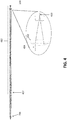
- FIG. 4 illustrates an embodiment of the present disclosure.
- an intermediate lens is positioned at a point 402, at or near the proximal input end of an end optic tube 412.
- the intermediate lens essentially compresses a diverging collimated image of an extended source multimode input fiber provided by lens 206, reducing the spread of the beam within the tube, forming an image of the input fiber 404 to be formed nominally at focus lens 202 at the distal end of the probe.
- the beam does not overfill (as illustrated in FIG. 3 ) the focus lens 202, and the focus at sample focus 420 is now an image of the probe head lens aperture and not the fiber.
- FIG. 4 improves laser beam transmission on the excitation path for longer end optic assemblies
- the solution as pictured for the tube length of FIG. 4 is sub-optimal insofar as the fiber image formed at the focus lens significantly underfills the focus lens 202. Underfilling the focus lens 202 results in reduced numerical aperture on the sample collection path, in turn reducing the solid angle of the omnidirectional light scatter collected from the sample.
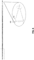
- FIG. 5 An improved solution for such a configuration is depicted in FIG. 5 , in which a longer focal length lens 502 is selected to compress the beam a bit less than in the embodiment of FIG. 4 so as to better fill the objective aperture of the focus lens 202.
- the focus lens 202 is now neither overfilled nor underfilled at point 504, thereby recovering the numerical aperture at the sample for improved light collection.
- the sample focus 520 in the sample is still an image of the probe head lens aperture and not the fiber.
- the fiber image is now positioned beyond the focus lens 202 and is within the window 204 at a position 522 in this example.
- the fiber image may become too large, and may again overfill the objective of the focus lens 202.
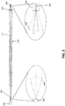
- longer end optics require a longer focal length intermediate lens, which in turn generates a larger fiber image 604 (minimum beam footprint) at focus lens 202.
- fiber image 604 minimum beam footprint
- a second intermediate lens 704 i.e., a field lens
- the second intermediate lens 704 desensitizes the long end optic to vignetting due to mechanical bending or angular error at the collet interface.
- the aperture of focus lens 202 is now underfilled at point 710, and the sample focus 720 in the sample is now a relayed image of the fiber and not an image of the probe lens aperture.
- the focal length can be further modified to better fill the focus lens 202 for an improved numerical aperture at the sample.
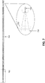
- the focal length of first intermediate lens 702 may be selected to image the fiber at (or near) a second intermediate lens 704.
- the longer focal length of lens 704 images the probe lens aperture beyond the focus lens 202 to better fill the focus lens aperture.
- the focus lens 202 is neither overfilled nor underfilled at point 810, and the sample focus 802 in the sample is now a relayed image of the fiber.
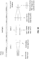
- FIG. 9 further illustrates how a design with two intermediate lenses in the end optic desensitizes probe performance to bending of the optic at the collet interface.
- the tube may be tilted at the interface 902 by a small angle, as a nonlimiting example, 0.4°.
- the beam aperture is decentered on intermediate lens 904 due to the tube tilt.
- intermediate lens 904 functions to steer the beam back toward the longitudinal axis of the tube at point 906.
- the beam is now better centered at point 910 than it was on lens 904.
- the image impinging on focus lens 202 is off-axis, this has a negligible effect on the position and quality of the sample focus 920.
- FIG. 10 illustrates an embodiment with two intermediate lenses in the end optic and shows a drum lens used to collimate light from the multimode fiber input (as well as focus the sample collection to the fiber for delivery to a spectrograph, not shown).
- the use of a drum lens is inconsequential, and may be replaced with a more generic lens collimator in the probe head.
- thin singlet lenses are used with optical materials selected for low background noise.
- lens or optics should be taken to include doublets or groups of lenses intended to perform the designated functions disclosed herein.
- excitation is delivered to, and light is collected from, a substantially homogeneous sample to characterize its constituents.
- the goal is maximum coupling of energy between the fiber(s) and the sample in both directions, with as high a numerical aperture as possible in the sample for maximum collection of excited spectra from the sample on the inbound path (e.g., Raman, fluorescence).
- the entire fiber numerical aperture is focused at the sample point without vignetting the outbound laser power.
- the focal spot can be an image of a fiber, the image of a lens aperture collimating a fiber, or a relay image of either.
- Such a relaxed requirement does not support a conventional multipixel imaging system, which must resolve different physical locations in the sample.
Landscapes
- Physics & Mathematics (AREA)
- General Physics & Mathematics (AREA)
- Health & Medical Sciences (AREA)
- Spectroscopy & Molecular Physics (AREA)
- Biochemistry (AREA)
- Life Sciences & Earth Sciences (AREA)
- Chemical & Material Sciences (AREA)
- Analytical Chemistry (AREA)
- General Health & Medical Sciences (AREA)
- Immunology (AREA)
- Pathology (AREA)
- Optics & Photonics (AREA)
- Nuclear Medicine, Radiotherapy & Molecular Imaging (AREA)
- Astronomy & Astrophysics (AREA)
- Investigating, Analyzing Materials By Fluorescence Or Luminescence (AREA)
Applications Claiming Priority (1)
| Application Number | Priority Date | Filing Date | Title |
|---|---|---|---|
| US15/592,506 US10481385B2 (en) | 2017-05-11 | 2017-05-11 | Endoscopic immersion probe end optics for laser spectroscopy |
Publications (2)
| Publication Number | Publication Date |
|---|---|
| EP3401669A1 true EP3401669A1 (fr) | 2018-11-14 |
| EP3401669B1 EP3401669B1 (fr) | 2023-06-07 |
Family
ID=62200242
Family Applications (1)
| Application Number | Title | Priority Date | Filing Date |
|---|---|---|---|
| EP18170989.0A Active EP3401669B1 (fr) | 2017-05-11 | 2018-05-07 | Sonde de spectroscopie raman |
Country Status (3)
| Country | Link |
|---|---|
| US (1) | US10481385B2 (fr) |
| EP (1) | EP3401669B1 (fr) |
| CN (1) | CN108872188B (fr) |
Families Citing this family (1)
| Publication number | Priority date | Publication date | Assignee | Title |
|---|---|---|---|---|
| CN115656141B (zh) * | 2022-11-15 | 2023-07-25 | 奥谱天成(厦门)光电有限公司 | 一种拉曼光谱探头 |
Citations (7)
| Publication number | Priority date | Publication date | Assignee | Title |
|---|---|---|---|---|
| FR2571144A1 (fr) * | 1984-10-01 | 1986-04-04 | Centre Nat Rech Scient | Dispositif notamment de multi-mesure pour analyser a distance et in situ, un echantillon par spectrometrie raman |
| US5295477A (en) * | 1992-05-08 | 1994-03-22 | Parviz Janfaza | Endoscopic operating microscope |
| US5841545A (en) * | 1994-09-19 | 1998-11-24 | Lockheed Martin Energy Systems, Inc. | Multi-function diamond film fiberoptic probe and measuring system employing same |
| US6876801B2 (en) * | 2002-06-10 | 2005-04-05 | Axiom Analytical, Inc. | Raman probe having a small diameter immersion tip |
| US6907149B2 (en) | 2002-02-01 | 2005-06-14 | Kaiser Optical Systems, Inc. | Compact optical measurement probe |
| US20120281211A1 (en) * | 2010-11-05 | 2012-11-08 | University Of Ottawa | Miniaturized multimodal cars endoscope |
| US20130331653A1 (en) * | 2010-12-08 | 2013-12-12 | Cornell University | Microscope apparatus, method and application |
Family Cites Families (19)
| Publication number | Priority date | Publication date | Assignee | Title |
|---|---|---|---|---|
| US3959581A (en) * | 1975-01-29 | 1976-05-25 | Zenith Radio Corporation | Self-compensating focus system for optical video playback device |
| US4735491A (en) * | 1983-12-28 | 1988-04-05 | Olympus Optical Co., Ltd. | Optical system for endoscopes |
| US5309541A (en) * | 1993-04-16 | 1994-05-03 | Laser Power Corporation | Flexible light conduit |
| JPH09248276A (ja) * | 1996-03-14 | 1997-09-22 | Olympus Optical Co Ltd | 視野方向可変硬性鏡装置 |
| CN100538836C (zh) * | 2002-10-18 | 2009-09-09 | 柯尼卡美能达精密光学株式会社 | 光拾取器装置用光学元件、中继透镜以及光拾取器装置 |
| JP4077716B2 (ja) * | 2002-11-20 | 2008-04-23 | オリンパス株式会社 | 内視鏡挿入方向検出装置 |
| JP4601266B2 (ja) * | 2003-05-30 | 2010-12-22 | オリンパス株式会社 | レーザ顕微鏡 |
| WO2006127967A2 (fr) * | 2005-05-25 | 2006-11-30 | Massachusetts Institute Of Technology | Systemes d'imagerie multifocaux et procedes associes |
| FR2900741B1 (fr) * | 2006-05-05 | 2008-07-18 | Mauna Kea Technologies Soc Par | Tete optique miniaturisee a haute resolution spatiale et haute sensibilite, notamment pour l'imagerie de fluorescence confocale fibree |
| JP4880686B2 (ja) * | 2006-06-20 | 2012-02-22 | パナソニック株式会社 | カップリングレンズ、光学ヘッドおよび光ディスク装置 |
| US7723657B2 (en) * | 2007-11-16 | 2010-05-25 | Mitutoyo Corporation | Focus detection apparatus having extended detection range |
| DE102009011647B4 (de) * | 2009-03-04 | 2020-02-20 | Carl Zeiss Meditec Ag | CARS-Endoskop |
| CN102063014A (zh) * | 2009-11-13 | 2011-05-18 | 上海微电子装备有限公司 | 一种用于微光刻的照明光学系统 |
| US8425037B2 (en) * | 2010-07-30 | 2013-04-23 | Adventus Technologies, Inc. | Intraoperative imaging system and apparatus |
| JP6033000B2 (ja) * | 2011-12-20 | 2016-11-30 | オリンパス株式会社 | 走査型内視鏡 |
| CN202891878U (zh) * | 2012-10-26 | 2013-04-24 | 成都海瑞康科技有限公司 | 防光晕的发光光学喉镜 |
| WO2014205007A1 (fr) * | 2013-06-17 | 2014-12-24 | Invenio Imaging Inc. | Procédés et systèmes pour une diffusion raman cohérente |
| DE102015205163B4 (de) * | 2015-03-23 | 2017-04-13 | Trumpf Werkzeugmaschinen Gmbh + Co. Kg | Optisches System für eine Laserbearbeitungsmaschine, mit einem optischen Element in einem Stecker eines Lichtleitkabels |
| WO2016187675A1 (fr) * | 2015-05-28 | 2016-12-01 | Cylite Pty Ltd | Appareil et procédé d'imagerie optique dans le domaine spectral 3d à haute résolution |
-
2017
- 2017-05-11 US US15/592,506 patent/US10481385B2/en active Active
-
2018
- 2018-05-07 EP EP18170989.0A patent/EP3401669B1/fr active Active
- 2018-05-10 CN CN201810442644.4A patent/CN108872188B/zh active Active
Patent Citations (7)
| Publication number | Priority date | Publication date | Assignee | Title |
|---|---|---|---|---|
| FR2571144A1 (fr) * | 1984-10-01 | 1986-04-04 | Centre Nat Rech Scient | Dispositif notamment de multi-mesure pour analyser a distance et in situ, un echantillon par spectrometrie raman |
| US5295477A (en) * | 1992-05-08 | 1994-03-22 | Parviz Janfaza | Endoscopic operating microscope |
| US5841545A (en) * | 1994-09-19 | 1998-11-24 | Lockheed Martin Energy Systems, Inc. | Multi-function diamond film fiberoptic probe and measuring system employing same |
| US6907149B2 (en) | 2002-02-01 | 2005-06-14 | Kaiser Optical Systems, Inc. | Compact optical measurement probe |
| US6876801B2 (en) * | 2002-06-10 | 2005-04-05 | Axiom Analytical, Inc. | Raman probe having a small diameter immersion tip |
| US20120281211A1 (en) * | 2010-11-05 | 2012-11-08 | University Of Ottawa | Miniaturized multimodal cars endoscope |
| US20130331653A1 (en) * | 2010-12-08 | 2013-12-12 | Cornell University | Microscope apparatus, method and application |
Also Published As
| Publication number | Publication date |
|---|---|
| EP3401669B1 (fr) | 2023-06-07 |
| US10481385B2 (en) | 2019-11-19 |
| US20180329196A1 (en) | 2018-11-15 |
| CN108872188A (zh) | 2018-11-23 |
| CN108872188B (zh) | 2021-07-13 |
Similar Documents
| Publication | Publication Date | Title |
|---|---|---|
| AU2018229081B2 (en) | Optical Scanner and Scanned Lens Optical Probe | |
| JP4149761B2 (ja) | 多光子内視鏡検査法 | |
| US6369928B1 (en) | Fiber-coupled, angled-dual-illumination-axis confocal scanning microscopes for performing reflective and two-photon fluorescence imaging | |
| US10690898B2 (en) | Light-field microscope with selective-plane illumination | |
| US10967452B2 (en) | Device for measuring the depth of a weld seam in real time | |
| JP5305035B2 (ja) | ファイバー共焦点蛍光撮像用の高空間分解能及び高感度小型光学ヘッド | |
| JP6397431B2 (ja) | リモート分光法のための光ファイバプローブ | |
| US20060187499A1 (en) | Connection unit and optical-scanning fluoroscopy apparatus | |
| EP3234455B1 (fr) | Homogénéisateur optique | |
| US6351325B1 (en) | Fiber-coupled, angled-dual-axis confocal scanning microscopes for imaging in a scattering medium | |
| JP2005512747A (ja) | 特に内視鏡用の小型化された集束用光学ヘッド | |
| EP4075181A1 (fr) | Système de microscope à éclairage oblique | |
| CN103557938B (zh) | 一种带照明和指示光的光谱采集器 | |
| CN112858250A (zh) | 一种超分辨显微成像系统 | |
| CN214669715U (zh) | 一种探头用光纤一体化透镜及内窥镜成像系统 | |
| Kim et al. | Objective-lens-free confocal endomicroscope using Lissajous scanning lensed-fiber | |
| US10481385B2 (en) | Endoscopic immersion probe end optics for laser spectroscopy | |
| US20150355444A1 (en) | Compact lens system for use in photoacoustic microscopy | |
| US11448551B2 (en) | Optical arrangement for a spectroscopic imaging method and spectroscopic imaging method | |
| JP5704827B2 (ja) | 蛍光観察装置 | |
| JP2010519579A (ja) | 共焦点レーザ顕微鏡 | |
| US11086123B2 (en) | Raman immersion probe optics | |
| Temprine et al. | Three-dimensional photoactivated localization microscopy with genetically expressed probes | |
| CN215457827U (zh) | 一种轻量化高稳定性的共聚焦显微内窥镜系统 | |
| US5253034A (en) | Device for displaying the core of an optical fiber |
Legal Events
| Date | Code | Title | Description |
|---|---|---|---|
| PUAI | Public reference made under article 153(3) epc to a published international application that has entered the european phase |
Free format text: ORIGINAL CODE: 0009012 |
|
| STAA | Information on the status of an ep patent application or granted ep patent |
Free format text: STATUS: THE APPLICATION HAS BEEN PUBLISHED |
|
| AK | Designated contracting states |
Kind code of ref document: A1 Designated state(s): AL AT BE BG CH CY CZ DE DK EE ES FI FR GB GR HR HU IE IS IT LI LT LU LV MC MK MT NL NO PL PT RO RS SE SI SK SM TR |
|
| AX | Request for extension of the european patent |
Extension state: BA ME |
|
| STAA | Information on the status of an ep patent application or granted ep patent |
Free format text: STATUS: REQUEST FOR EXAMINATION WAS MADE |
|
| 17P | Request for examination filed |
Effective date: 20190514 |
|
| RBV | Designated contracting states (corrected) |
Designated state(s): AL AT BE BG CH CY CZ DE DK EE ES FI FR GB GR HR HU IE IS IT LI LT LU LV MC MK MT NL NO PL PT RO RS SE SI SK SM TR |
|
| STAA | Information on the status of an ep patent application or granted ep patent |
Free format text: STATUS: EXAMINATION IS IN PROGRESS |
|
| 17Q | First examination report despatched |
Effective date: 20191219 |
|
| RAP1 | Party data changed (applicant data changed or rights of an application transferred) |
Owner name: ENDRESS+HAUSER OPTICAL ANALYSIS, INC. |
|
| GRAP | Despatch of communication of intention to grant a patent |
Free format text: ORIGINAL CODE: EPIDOSNIGR1 |
|
| STAA | Information on the status of an ep patent application or granted ep patent |
Free format text: STATUS: GRANT OF PATENT IS INTENDED |
|
| RIC1 | Information provided on ipc code assigned before grant |
Ipc: A61B 1/00 19680901ALN20230104BHEP Ipc: G01J 3/02 19680901ALI20230104BHEP Ipc: G02B 23/24 19850101ALI20230104BHEP Ipc: G01N 21/85 19800101ALI20230104BHEP Ipc: G01N 21/65 19800101ALI20230104BHEP Ipc: G01J 3/44 19680901ALI20230104BHEP Ipc: G01N 21/64 19800101AFI20230104BHEP |
|
| INTG | Intention to grant announced |
Effective date: 20230124 |
|
| GRAS | Grant fee paid |
Free format text: ORIGINAL CODE: EPIDOSNIGR3 |
|
| GRAA | (expected) grant |
Free format text: ORIGINAL CODE: 0009210 |
|
| STAA | Information on the status of an ep patent application or granted ep patent |
Free format text: STATUS: THE PATENT HAS BEEN GRANTED |
|
| AK | Designated contracting states |
Kind code of ref document: B1 Designated state(s): AL AT BE BG CH CY CZ DE DK EE ES FI FR GB GR HR HU IE IS IT LI LT LU LV MC MK MT NL NO PL PT RO RS SE SI SK SM TR |
|
| REG | Reference to a national code |
Ref country code: GB Ref legal event code: FG4D |
|
| REG | Reference to a national code |
Ref country code: CH Ref legal event code: EP Ref country code: AT Ref legal event code: REF Ref document number: 1576542 Country of ref document: AT Kind code of ref document: T Effective date: 20230615 Ref country code: DE Ref legal event code: R096 Ref document number: 602018050698 Country of ref document: DE |
|
| P01 | Opt-out of the competence of the unified patent court (upc) registered |
Effective date: 20230601 |
|
| REG | Reference to a national code |
Ref country code: LT Ref legal event code: MG9D |
|
| REG | Reference to a national code |
Ref country code: NL Ref legal event code: MP Effective date: 20230607 |
|
| PG25 | Lapsed in a contracting state [announced via postgrant information from national office to epo] |
Ref country code: SE Free format text: LAPSE BECAUSE OF FAILURE TO SUBMIT A TRANSLATION OF THE DESCRIPTION OR TO PAY THE FEE WITHIN THE PRESCRIBED TIME-LIMIT Effective date: 20230607 Ref country code: NO Free format text: LAPSE BECAUSE OF FAILURE TO SUBMIT A TRANSLATION OF THE DESCRIPTION OR TO PAY THE FEE WITHIN THE PRESCRIBED TIME-LIMIT Effective date: 20230907 Ref country code: ES Free format text: LAPSE BECAUSE OF FAILURE TO SUBMIT A TRANSLATION OF THE DESCRIPTION OR TO PAY THE FEE WITHIN THE PRESCRIBED TIME-LIMIT Effective date: 20230607 |
|
| REG | Reference to a national code |
Ref country code: AT Ref legal event code: MK05 Ref document number: 1576542 Country of ref document: AT Kind code of ref document: T Effective date: 20230607 |
|
| PG25 | Lapsed in a contracting state [announced via postgrant information from national office to epo] |
Ref country code: RS Free format text: LAPSE BECAUSE OF FAILURE TO SUBMIT A TRANSLATION OF THE DESCRIPTION OR TO PAY THE FEE WITHIN THE PRESCRIBED TIME-LIMIT Effective date: 20230607 Ref country code: NL Free format text: LAPSE BECAUSE OF FAILURE TO SUBMIT A TRANSLATION OF THE DESCRIPTION OR TO PAY THE FEE WITHIN THE PRESCRIBED TIME-LIMIT Effective date: 20230607 Ref country code: LV Free format text: LAPSE BECAUSE OF FAILURE TO SUBMIT A TRANSLATION OF THE DESCRIPTION OR TO PAY THE FEE WITHIN THE PRESCRIBED TIME-LIMIT Effective date: 20230607 Ref country code: LT Free format text: LAPSE BECAUSE OF FAILURE TO SUBMIT A TRANSLATION OF THE DESCRIPTION OR TO PAY THE FEE WITHIN THE PRESCRIBED TIME-LIMIT Effective date: 20230607 Ref country code: HR Free format text: LAPSE BECAUSE OF FAILURE TO SUBMIT A TRANSLATION OF THE DESCRIPTION OR TO PAY THE FEE WITHIN THE PRESCRIBED TIME-LIMIT Effective date: 20230607 Ref country code: GR Free format text: LAPSE BECAUSE OF FAILURE TO SUBMIT A TRANSLATION OF THE DESCRIPTION OR TO PAY THE FEE WITHIN THE PRESCRIBED TIME-LIMIT Effective date: 20230908 |
|
| PG25 | Lapsed in a contracting state [announced via postgrant information from national office to epo] |
Ref country code: FI Free format text: LAPSE BECAUSE OF FAILURE TO SUBMIT A TRANSLATION OF THE DESCRIPTION OR TO PAY THE FEE WITHIN THE PRESCRIBED TIME-LIMIT Effective date: 20230607 |
|
| PG25 | Lapsed in a contracting state [announced via postgrant information from national office to epo] |
Ref country code: SK Free format text: LAPSE BECAUSE OF FAILURE TO SUBMIT A TRANSLATION OF THE DESCRIPTION OR TO PAY THE FEE WITHIN THE PRESCRIBED TIME-LIMIT Effective date: 20230607 |
|
| PG25 | Lapsed in a contracting state [announced via postgrant information from national office to epo] |
Ref country code: IS Free format text: LAPSE BECAUSE OF FAILURE TO SUBMIT A TRANSLATION OF THE DESCRIPTION OR TO PAY THE FEE WITHIN THE PRESCRIBED TIME-LIMIT Effective date: 20231007 |
|
| PG25 | Lapsed in a contracting state [announced via postgrant information from national office to epo] |
Ref country code: SM Free format text: LAPSE BECAUSE OF FAILURE TO SUBMIT A TRANSLATION OF THE DESCRIPTION OR TO PAY THE FEE WITHIN THE PRESCRIBED TIME-LIMIT Effective date: 20230607 Ref country code: SK Free format text: LAPSE BECAUSE OF FAILURE TO SUBMIT A TRANSLATION OF THE DESCRIPTION OR TO PAY THE FEE WITHIN THE PRESCRIBED TIME-LIMIT Effective date: 20230607 Ref country code: RO Free format text: LAPSE BECAUSE OF FAILURE TO SUBMIT A TRANSLATION OF THE DESCRIPTION OR TO PAY THE FEE WITHIN THE PRESCRIBED TIME-LIMIT Effective date: 20230607 Ref country code: PT Free format text: LAPSE BECAUSE OF FAILURE TO SUBMIT A TRANSLATION OF THE DESCRIPTION OR TO PAY THE FEE WITHIN THE PRESCRIBED TIME-LIMIT Effective date: 20231009 Ref country code: IS Free format text: LAPSE BECAUSE OF FAILURE TO SUBMIT A TRANSLATION OF THE DESCRIPTION OR TO PAY THE FEE WITHIN THE PRESCRIBED TIME-LIMIT Effective date: 20231007 Ref country code: EE Free format text: LAPSE BECAUSE OF FAILURE TO SUBMIT A TRANSLATION OF THE DESCRIPTION OR TO PAY THE FEE WITHIN THE PRESCRIBED TIME-LIMIT Effective date: 20230607 Ref country code: CZ Free format text: LAPSE BECAUSE OF FAILURE TO SUBMIT A TRANSLATION OF THE DESCRIPTION OR TO PAY THE FEE WITHIN THE PRESCRIBED TIME-LIMIT Effective date: 20230607 Ref country code: AT Free format text: LAPSE BECAUSE OF FAILURE TO SUBMIT A TRANSLATION OF THE DESCRIPTION OR TO PAY THE FEE WITHIN THE PRESCRIBED TIME-LIMIT Effective date: 20230607 |
|
| PG25 | Lapsed in a contracting state [announced via postgrant information from national office to epo] |
Ref country code: PL Free format text: LAPSE BECAUSE OF FAILURE TO SUBMIT A TRANSLATION OF THE DESCRIPTION OR TO PAY THE FEE WITHIN THE PRESCRIBED TIME-LIMIT Effective date: 20230607 |
|
| REG | Reference to a national code |
Ref country code: DE Ref legal event code: R097 Ref document number: 602018050698 Country of ref document: DE |
|
| PLBE | No opposition filed within time limit |
Free format text: ORIGINAL CODE: 0009261 |
|
| STAA | Information on the status of an ep patent application or granted ep patent |
Free format text: STATUS: NO OPPOSITION FILED WITHIN TIME LIMIT |
|
| PG25 | Lapsed in a contracting state [announced via postgrant information from national office to epo] |
Ref country code: DK Free format text: LAPSE BECAUSE OF FAILURE TO SUBMIT A TRANSLATION OF THE DESCRIPTION OR TO PAY THE FEE WITHIN THE PRESCRIBED TIME-LIMIT Effective date: 20230607 |
|
| PG25 | Lapsed in a contracting state [announced via postgrant information from national office to epo] |
Ref country code: SI Free format text: LAPSE BECAUSE OF FAILURE TO SUBMIT A TRANSLATION OF THE DESCRIPTION OR TO PAY THE FEE WITHIN THE PRESCRIBED TIME-LIMIT Effective date: 20230607 |
|
| 26N | No opposition filed |
Effective date: 20240308 |
|
| PG25 | Lapsed in a contracting state [announced via postgrant information from national office to epo] |
Ref country code: SI Free format text: LAPSE BECAUSE OF FAILURE TO SUBMIT A TRANSLATION OF THE DESCRIPTION OR TO PAY THE FEE WITHIN THE PRESCRIBED TIME-LIMIT Effective date: 20230607 Ref country code: IT Free format text: LAPSE BECAUSE OF FAILURE TO SUBMIT A TRANSLATION OF THE DESCRIPTION OR TO PAY THE FEE WITHIN THE PRESCRIBED TIME-LIMIT Effective date: 20230607 |
|
| PG25 | Lapsed in a contracting state [announced via postgrant information from national office to epo] |
Ref country code: BG Free format text: LAPSE BECAUSE OF FAILURE TO SUBMIT A TRANSLATION OF THE DESCRIPTION OR TO PAY THE FEE WITHIN THE PRESCRIBED TIME-LIMIT Effective date: 20230607 |
|
| PG25 | Lapsed in a contracting state [announced via postgrant information from national office to epo] |
Ref country code: BG Free format text: LAPSE BECAUSE OF FAILURE TO SUBMIT A TRANSLATION OF THE DESCRIPTION OR TO PAY THE FEE WITHIN THE PRESCRIBED TIME-LIMIT Effective date: 20230607 |
|
| REG | Reference to a national code |
Ref country code: CH Ref legal event code: PL |
|
| PG25 | Lapsed in a contracting state [announced via postgrant information from national office to epo] |
Ref country code: MC Free format text: LAPSE BECAUSE OF FAILURE TO SUBMIT A TRANSLATION OF THE DESCRIPTION OR TO PAY THE FEE WITHIN THE PRESCRIBED TIME-LIMIT Effective date: 20230607 |
|
| PG25 | Lapsed in a contracting state [announced via postgrant information from national office to epo] |
Ref country code: LU Free format text: LAPSE BECAUSE OF NON-PAYMENT OF DUE FEES Effective date: 20240507 |
|
| GBPC | Gb: european patent ceased through non-payment of renewal fee |
Effective date: 20240507 |
|
| PG25 | Lapsed in a contracting state [announced via postgrant information from national office to epo] |
Ref country code: MC Free format text: LAPSE BECAUSE OF FAILURE TO SUBMIT A TRANSLATION OF THE DESCRIPTION OR TO PAY THE FEE WITHIN THE PRESCRIBED TIME-LIMIT Effective date: 20230607 Ref country code: LU Free format text: LAPSE BECAUSE OF NON-PAYMENT OF DUE FEES Effective date: 20240507 Ref country code: CH Free format text: LAPSE BECAUSE OF NON-PAYMENT OF DUE FEES Effective date: 20240531 |
|
| REG | Reference to a national code |
Ref country code: BE Ref legal event code: MM Effective date: 20240531 |
|
| PG25 | Lapsed in a contracting state [announced via postgrant information from national office to epo] |
Ref country code: IE Free format text: LAPSE BECAUSE OF NON-PAYMENT OF DUE FEES Effective date: 20240507 |
|
| PG25 | Lapsed in a contracting state [announced via postgrant information from national office to epo] |
Ref country code: BE Free format text: LAPSE BECAUSE OF NON-PAYMENT OF DUE FEES Effective date: 20240531 |
|
| PG25 | Lapsed in a contracting state [announced via postgrant information from national office to epo] |
Ref country code: FR Free format text: LAPSE BECAUSE OF NON-PAYMENT OF DUE FEES Effective date: 20240531 |
|
| PG25 | Lapsed in a contracting state [announced via postgrant information from national office to epo] |
Ref country code: GB Free format text: LAPSE BECAUSE OF NON-PAYMENT OF DUE FEES Effective date: 20240507 |
|
| PGFP | Annual fee paid to national office [announced via postgrant information from national office to epo] |
Ref country code: DE Payment date: 20250521 Year of fee payment: 8 |
|
| PG25 | Lapsed in a contracting state [announced via postgrant information from national office to epo] |
Ref country code: CY Free format text: LAPSE BECAUSE OF FAILURE TO SUBMIT A TRANSLATION OF THE DESCRIPTION OR TO PAY THE FEE WITHIN THE PRESCRIBED TIME-LIMIT; INVALID AB INITIO Effective date: 20180507 |
|
| PG25 | Lapsed in a contracting state [announced via postgrant information from national office to epo] |
Ref country code: HU Free format text: LAPSE BECAUSE OF FAILURE TO SUBMIT A TRANSLATION OF THE DESCRIPTION OR TO PAY THE FEE WITHIN THE PRESCRIBED TIME-LIMIT; INVALID AB INITIO Effective date: 20180507 |