EP3401694B1 - Identifizierungsverfahren des elektrischen widerstands eines rotors eines elektromotors - Google Patents
Identifizierungsverfahren des elektrischen widerstands eines rotors eines elektromotors Download PDFInfo
- Publication number
- EP3401694B1 EP3401694B1 EP18167159.5A EP18167159A EP3401694B1 EP 3401694 B1 EP3401694 B1 EP 3401694B1 EP 18167159 A EP18167159 A EP 18167159A EP 3401694 B1 EP3401694 B1 EP 3401694B1
- Authority
- EP
- European Patent Office
- Prior art keywords
- rotor
- ref
- value
- resistance
- electric motor
- Prior art date
- Legal status (The legal status is an assumption and is not a legal conclusion. Google has not performed a legal analysis and makes no representation as to the accuracy of the status listed.)
- Active
Links
Images


Classifications
-
- G—PHYSICS
- G01—MEASURING; TESTING
- G01R—MEASURING ELECTRIC VARIABLES; MEASURING MAGNETIC VARIABLES
- G01R27/00—Arrangements for measuring resistance, reactance, impedance, or electric characteristics derived therefrom
- G01R27/02—Measuring real or complex resistance, reactance, impedance, or other two-pole characteristics derived therefrom, e.g. time constant
- G01R27/14—Measuring resistance by measuring current or voltage obtained from a reference source
-
- H—ELECTRICITY
- H02—GENERATION; CONVERSION OR DISTRIBUTION OF ELECTRIC POWER
- H02P—CONTROL OR REGULATION OF ELECTRIC MOTORS, ELECTRIC GENERATORS OR DYNAMO-ELECTRIC CONVERTERS; CONTROLLING TRANSFORMERS, REACTORS OR CHOKE COILS
- H02P21/00—Arrangements or methods for the control of electric machines by vector control, e.g. by control of field orientation
- H02P21/0003—Control strategies in general, e.g. linear type, e.g. P, PI, PID, using robust control
-
- G—PHYSICS
- G01—MEASURING; TESTING
- G01R—MEASURING ELECTRIC VARIABLES; MEASURING MAGNETIC VARIABLES
- G01R31/00—Arrangements for testing electric properties; Arrangements for locating electric faults; Arrangements for electrical testing characterised by what is being tested not provided for elsewhere
- G01R31/34—Testing dynamo-electric machines
-
- G—PHYSICS
- G01—MEASURING; TESTING
- G01R—MEASURING ELECTRIC VARIABLES; MEASURING MAGNETIC VARIABLES
- G01R31/00—Arrangements for testing electric properties; Arrangements for locating electric faults; Arrangements for electrical testing characterised by what is being tested not provided for elsewhere
- G01R31/34—Testing dynamo-electric machines
- G01R31/343—Testing dynamo-electric machines in operation
-
- H—ELECTRICITY
- H02—GENERATION; CONVERSION OR DISTRIBUTION OF ELECTRIC POWER
- H02P—CONTROL OR REGULATION OF ELECTRIC MOTORS, ELECTRIC GENERATORS OR DYNAMO-ELECTRIC CONVERTERS; CONTROLLING TRANSFORMERS, REACTORS OR CHOKE COILS
- H02P21/00—Arrangements or methods for the control of electric machines by vector control, e.g. by control of field orientation
- H02P21/14—Estimation or adaptation of machine parameters, e.g. flux, current or voltage
-
- H—ELECTRICITY
- H02—GENERATION; CONVERSION OR DISTRIBUTION OF ELECTRIC POWER
- H02P—CONTROL OR REGULATION OF ELECTRIC MOTORS, ELECTRIC GENERATORS OR DYNAMO-ELECTRIC CONVERTERS; CONTROLLING TRANSFORMERS, REACTORS OR CHOKE COILS
- H02P21/00—Arrangements or methods for the control of electric machines by vector control, e.g. by control of field orientation
- H02P21/22—Current control, e.g. using a current control loop
-
- H—ELECTRICITY
- H02—GENERATION; CONVERSION OR DISTRIBUTION OF ELECTRIC POWER
- H02P—CONTROL OR REGULATION OF ELECTRIC MOTORS, ELECTRIC GENERATORS OR DYNAMO-ELECTRIC CONVERTERS; CONTROLLING TRANSFORMERS, REACTORS OR CHOKE COILS
- H02P23/00—Arrangements or methods for the control of AC motors characterised by a control method other than vector control
- H02P23/0077—Characterised by the use of a particular software algorithm
-
- H—ELECTRICITY
- H02—GENERATION; CONVERSION OR DISTRIBUTION OF ELECTRIC POWER
- H02P—CONTROL OR REGULATION OF ELECTRIC MOTORS, ELECTRIC GENERATORS OR DYNAMO-ELECTRIC CONVERTERS; CONTROLLING TRANSFORMERS, REACTORS OR CHOKE COILS
- H02P23/00—Arrangements or methods for the control of AC motors characterised by a control method other than vector control
- H02P23/14—Estimation or adaptation of motor parameters, e.g. rotor time constant, flux, speed, current or voltage
Definitions
- the present invention relates to a method for identifying the electrical resistance of the rotor of an electric induction motor.
- the invention also relates to the identification system for implementing said method.
- An electric motor is controlled by a variable speed drive, implementing a suitable control law.
- the drive controller and its processing unit must rely on certain parameters of the controlled electric motor.
- variable speed drive relies on parameters whose values are exact. This is particularly the case of the rotor resistance (also called “rotor resistance”) of the electric motor. Now it turns out that this exact value of the resistance of the rotor is not necessarily known to the processing unit of the drive controller. The processing unit can then for example use a default value in the command, which very often results in degraded performance. The rotor resistance may indeed be over-estimated or underestimated by the processing unit, resulting in a variation of the current in the stator and therefore an error in the implementation of the algorithm for calculating the voltages of the law of command.
- the patent EP1713173B1 describes for its part a solution for adjusting the parameters of an electric motor. It is implemented online, that is to say during normal operation of the engine. It consists mainly in using the integral term of the current loop to adjust the values of the parameters of the motor model.
- the object of the invention is therefore to propose a new method for identifying the resistance of the rotor, which is reliable, does not require the use of a speed sensor (closed loop) and which can be implemented in the presence of a load or in the absence of a load on the engine.
- said predetermined value corresponds to a zero value or close to zero.
- the method is implemented according to a dichotomy principle comprising several successive iterations and in which, at each iteration, an interval in which the value sought for the rotor resistance is divided by two.
- the method is implemented according to a gradient principle comprising several successive iterations and in which the value chosen for the resistance of the rotor is modified at each iteration according to the direction of the result of the comparison step.
- said predetermined value corresponds to a zero value or close to zero.
- this system is configured to operate according to a dichotomy principle comprising several successive iterations and in which, at each iteration, an interval in which the value sought for the rotor resistance is divided by two.
- the system is configured to operate according to a gradient principle comprising several successive iterations and in which the value chosen for the resistance of the rotor is modified at each iteration according to the direction of the result of the comparison step.
- variable speed drive for controlling an electric motor, which comprises a control system comprising an identification system according to that defined above.
- the invention described below applies to the control of an asynchronous M induction motor, preferably with a three-phase power supply. It is implemented in a conventional control scheme of vector or scalar type, in open loop, that is to say without return of a measurement of speed at the electric motor, or in a closed loop, it is ie with a return of a speed measurement at the electric motor.
- the identification method of the invention is implemented in a control system which comprises a processing unit UC.
- the CPU processing unit comprises at least one microprocessor and a memory.
- This control system is associated with a variable speed drive for controlling an electric motor. It may in particular be integrated with said variable speed drive.
- This control law is implemented during an operating phase, that is to say during the normal operation of the electric motor M controlled by the variable speed drive.
- the invention relates more particularly to a method of identifying the resistance of the rotor of the electric motor. This identification can be implemented prior to normal operation of the motor or at any other time during a parameterization phase of the variable speed drive.
- the identification method is implemented by an identification system, preferably executed by the CPU unit of the drive controller.
- This identification system relies notably on the M1 to M4 modules of the control system and on a complementary M5 module helping to identify the rotor resistance.
- the current and voltage measurement means will advantageously be integrated into the identification system of the invention and the measurement steps used will advantageously be part of the identification method of the invention.
- the identification process is based on the following demonstrations in which the index "R” makes it possible to identify the parameters linked to the rotor, the index “S” makes it possible to identify parameters related to the stator, the exponent "ref” makes it possible to identify a reference parameter.
- f i R ref The SAT ⁇ i R ref ⁇ 1 1 + ⁇ ⁇
- the general principle of the invention is to set up an efficient algorithm that converges to the desired value of the rotor resistance R r .
- the three blocks B1, B2, B3 are notably integrated in the modules M1 to M5 of the control system described above.
- the block B1 is for example executed in the module M2 allowing the calculation of the control voltages.
- Block B2 is for example executed in module M2 for calculating voltages.
- the block B3 is for example executed in the module M5 making it possible to process the stator current acquired during the measurements and to deduce the new theoretical value R r to be assigned to the resistance of the rotor according to the chosen search solution (see below ).
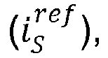
- the predetermined value i S ref stator current i s to be obtained which corresponds to the exact value of the rotor resistance R r is close to zero, preferably equal to zero.
- the stator current i s obtained during the implementation of the solution of the invention is that close to zero, typically rated current divided by 50, preferably nothing.
- the parameters used are RMAX, RMIN which correspond to the extreme limits of each interval in which the value of the rotor resistance is sought and a number N of iterations.
- RMAX which correspond to the extreme limits of each interval in which the value of the rotor resistance is sought
- N the number of iterations.
- the width of the range of possible values to assign the rotor resistance is divided by two.
- the value of the rotor resistance is in the last explored interval. The more restricted it is, the more precise the value will be.
- the principle is illustrated more precisely on the figure 4 .
- the figure 5 thus illustrates the principle of the identification method of the invention, using a search by dichotomy.
- the number of iterations is represented on the abscissa and the value assigned to the rotor resistance R r updated after each iteration is represented on the ordinate.
- the second research solution mentioned above consists in varying the value assigned to the rotor resistance R r increasing or decreasing according to the variation of the stator current ls obtained at each new iteration. This method being easily understandable, it is not detailed in the present application.
Landscapes
- Engineering & Computer Science (AREA)
- Power Engineering (AREA)
- Physics & Mathematics (AREA)
- General Physics & Mathematics (AREA)
- Control Of Ac Motors In General (AREA)
Claims (11)
- Verfahren zur Identifizierung eines Widerstandswertes (Rr ) des Rotors eines elektrischen Induktionsmotors (M), dadurch gekennzeichnet, dass es die folgenden Schritte umfasst:a) Bestimmung einer Referenzspannung
 b) Anlegen einer Steuerspannung (us ) an den Elektromotor, wobei die Steuerspannung aus der Referenzspannung
 c) Erfassung der Werte der Ströme (i 1, i 2, i 3), die in den drei Phasen des Elektromotors gemessen werden, um daraus einen Statorstrom (is ) des Elektromotors abzuleiten,d) Vergleich des erhaltenen Statorstroms (is ) mit einem vorbestimmten Wert
 e) Korrektur des für den Widerstand (Rr ) des Rotors verwendeten Wertes (R̂r ) und Anwendung der Schritte a) bis d), bis ein Statorstrom (is ) erhalten wird. der gleich dem vorbestimmten Wert ist.
 - Verfahren zur Identifizierung eines Widerstandswertes (Rr ) des Rotors eines elektrischen Induktionsmotors (M), dadurch gekennzeichnet, dass es die folgenden Schritte umfasst:a) Bestimmung einer Messspannung

 b) Bestimmung einer Referenzspannung
 c) Vergleich der Referenzspannung mit der Messspannung,d) Korrektur des für den Widerstand (Rr ) des Rotors verwendeten Wertes (R̂r ) und Anwendung der Schritte a) bis c), bis eine Gleichheit zwischen der Referenzspannung und der Messspannung erhalten wird.
 - Verfahren nach Anspruch 1 oder 2, dadurch gekennzeichnet, dass der vorbestimmte Wert

- Verfahren nach Anspruch 3, dadurch gekennzeichnet, dass es gemäß einem Dichotomieprinzip durchgeführt wird, das mehrere aufeinander folgende Iterationen umfasst und bei dem in jeder Iteration ein Intervall, in dem sich der gesuchte Wert für den Widerstand des Rotors befindet, halbiert wird.
- Verfahren nach Anspruch 3, dadurch gekennzeichnet, dass es gemäß einem Gradientenprinzip durchgeführt wird, das mehrere aufeinander folgende Iterationen umfasst und bei dem der für den Widerstand des Rotors gewählte Wert (R̂r ) bei jeder Iteration in Abhängigkeit von der Richtung des Ergebnisses des Vergleichsschrittes geändert wird.
- System zur Identifizierung eines Widerstandswertes (Rr ) des Rotors eines elektrischen Induktionsmotors (M), dadurch gekennzeichnet, dass es aufweist:a) ein Modul zur Bestimmung einer Referenzspannung
 b) ein Modul zum Anlegen von Steuerspannungen (us ) an den Elektromotor, wobei die Steuerspannungen aus der Referenzspannung
 c) ein Modul zur Erfassung der Werte der Ströme (i 1, i 2, i 3), die in den drei Phasen des Elektromotors gemessen werden, um daraus einen Statorstrom (is ) des Elektromotors abzuleiten,d) ein Modul zum Vergleich des erhaltenen Statorstroms (is ) mit einem vorbestimmten Wert
 e) ein Modul zur Korrektur des für den Widerstand (Rr ) des Rotors verwendeten Wertes (R̂r ) und Ausführung der Module a) bis d), bis ein Statorstrom erhalten wird. der gleich dem vorbestimmten Wert
- System zur Identifizierung eines Widerstandswertes (Rr ) des Rotors eines elektrischen Induktionsmotors (M), dadurch gekennzeichnet, dass es aufweist:a) ein Modul zur Bestimmung einer Messspannung

 b) ein Modul zur Bestimmung einer Referenzspannung
 c) ein Modul zum Vergleich der Referenzspannung mit der Messspannung,d) ein Modul zur Korrektur des für den Widerstand (Rr ) des Rotors verwendeten Wertes (R̂r ) und Ausführung der Module a) bis c), bis eine Gleichheit zwischen der Referenzspannung und der Messspannung erhalten wird.
 - System nach Anspruch 6 oder 7, dadurch gekennzeichnet, dass der vorbestimmte Wert einem Wert von null oder nahe bei null entspricht.
- System nach Anspruch 8, dadurch gekennzeichnet, dass es dafür ausgelegt ist, gemäß einem Dichotomieprinzip zu arbeiten, das mehrere aufeinander folgende Iterationen umfasst und bei dem in jeder Iteration ein Intervall, in dem sich der gesuchte Wert für den Widerstand des Rotors befindet, halbiert wird.
- System nach Anspruch 8, dadurch gekennzeichnet, dass es dafür ausgelegt ist, gemäß einem Gradientenprinzip zu arbeiten, das mehrere aufeinanderfolgende Iterationen umfasst und bei dem der für den Widerstand des Rotors gewählte Wert (R̂r ) bei jeder Iteration in Abhängigkeit von der Richtung des Ergebnisses des Vergleichsschrittes geändert wird.
- Umrichter, welcher zur Steuerung eines Elektromotors bestimmt ist, dadurch gekennzeichnet, dass er ein Steuerungssystem aufweist, das ein System zur Identifizierung umfasst, das mit demjenigen konform ist, das in einem der Ansprüche 6 bis 10 definiert ist.
Applications Claiming Priority (1)
| Application Number | Priority Date | Filing Date | Title |
|---|---|---|---|
| FR1754076A FR3066276B1 (fr) | 2017-05-10 | 2017-05-10 | Procede d'identification de la resistance electrique du rotor d'un moteur electrique |
Publications (2)
| Publication Number | Publication Date |
|---|---|
| EP3401694A1 EP3401694A1 (de) | 2018-11-14 |
| EP3401694B1 true EP3401694B1 (de) | 2019-06-12 |
Family
ID=59811428
Family Applications (1)
| Application Number | Title | Priority Date | Filing Date |
|---|---|---|---|
| EP18167159.5A Active EP3401694B1 (de) | 2017-05-10 | 2018-04-13 | Identifizierungsverfahren des elektrischen widerstands eines rotors eines elektromotors |
Country Status (6)
| Country | Link |
|---|---|
| US (1) | US10551418B2 (de) |
| EP (1) | EP3401694B1 (de) |
| JP (1) | JP7117893B2 (de) |
| CN (1) | CN108880367B (de) |
| ES (1) | ES2743609T3 (de) |
| FR (1) | FR3066276B1 (de) |
Families Citing this family (4)
| Publication number | Priority date | Publication date | Assignee | Title |
|---|---|---|---|---|
| FR3096141B1 (fr) * | 2019-05-15 | 2021-06-04 | Alstom Transp Tech | Dispositif électronique et procédé d'estimation d'une résistance rotorique d'une machine électrique |
| CN112881807B (zh) * | 2021-01-08 | 2023-11-14 | 大唐长春第二热电有限责任公司 | 发电机转子回路电阻和碳刷回路电阻测量工具及方法 |
| CN114157205B (zh) * | 2021-12-10 | 2023-08-22 | 重庆大学 | 基于稳态电量幅值采样的无刷双馈电机集成参数辨识方法 |
| CN118962241B (zh) * | 2024-07-22 | 2025-04-15 | 深圳行动元智能科技有限公司 | 采样电阻的检测方法、驱动器及计算机可读存储介质 |
Family Cites Families (20)
| Publication number | Priority date | Publication date | Assignee | Title |
|---|---|---|---|---|
| US4670698A (en) * | 1983-12-02 | 1987-06-02 | Imec Corporation | Adaptive induction motor controller |
| FR2665589B1 (fr) * | 1990-08-01 | 1992-10-09 | Alsthom Gec | Procede et dispositif d'estimation de flux d'induction magnetique d'un moteur asynchrone, en vue notamment de la commande de ce moteur par regulation de flux. |
| JPH0956189A (ja) * | 1995-08-21 | 1997-02-25 | Hitachi Ltd | 交流モータ制御装置 |
| DE19709296A1 (de) * | 1997-03-06 | 1998-09-24 | Siemens Ag | Verfahren und Vorrichtung zur Identifikation der Systemparameter Statorwiderstand und Rotorwiderstand einer geberlosen, feldorientiert betriebenen Drehfeldmaschine |
| US5880415A (en) * | 1997-12-22 | 1999-03-09 | Otis Elevator Company | Automatic calibration of current regulator control compensation for an elevator motor drive with locked rotor |
| US7412339B2 (en) * | 2002-05-24 | 2008-08-12 | Virginia Tech Intellectual Properties, Inc. | Method and apparatus for identifying an operational phase of a motor phase winding and controlling energization of the phase winding |
| FR2884658B1 (fr) * | 2005-04-13 | 2007-05-18 | Schneider Toshiba Inverter | Procede d'ajustement de parametres d'un moteur electrique et variateur de vitesse utilisant un tel procede |
| JP2008086129A (ja) * | 2006-09-28 | 2008-04-10 | Hitachi Ltd | 交流電動機の制御装置および定数測定装置 |
| JP5167631B2 (ja) * | 2006-11-30 | 2013-03-21 | 株式会社デンソー | モータの制御方法及びそれを利用するモータ制御装置 |
| US7560895B2 (en) * | 2007-03-16 | 2009-07-14 | Azure Dynamics, Inc. | Indirect rotor resistance estimation system and method |
| EP2453248B1 (de) * | 2010-11-15 | 2013-06-26 | ABB Oy | Verfahren und Anordnung zur Bestimmung der Induktivitäten einer synchronen Reluktanzmaschine |
| CN102510263B (zh) * | 2011-10-25 | 2014-10-22 | 中国电力科学研究院 | 基于抛载试验和数值差分的同步发电机实用参数辨识方法 |
| CN103185839B (zh) * | 2011-12-30 | 2015-07-08 | 台达电子企业管理(上海)有限公司 | 永磁电机电感参数测量装置及其方法 |
| CN102624320B (zh) * | 2012-01-13 | 2014-04-23 | 重庆交通大学 | 基于定子电阻观测器的电动机动/稳态阶段参数辨识方法 |
| GB2503040B (en) * | 2012-06-15 | 2020-05-06 | Danfoss Drives As | Variable torque angle for electric motor |
| US20150177328A1 (en) * | 2012-08-09 | 2015-06-25 | Danfoss Power Electronics A/S | Automated motor adaptation |
| KR101619567B1 (ko) * | 2012-11-09 | 2016-05-18 | 엘에스산전 주식회사 | 유도전동기의 파라미터 추정장치 |
| US8988035B2 (en) * | 2012-12-19 | 2015-03-24 | Eaton Corporation | System for determining a magnetizing curve and rotor resistance of an induction machine and method of making same |
| KR102286371B1 (ko) * | 2014-06-19 | 2021-08-05 | 현대모비스 주식회사 | 모터 온도 변화 제어 장치 및 방법 |
| FR3042332B1 (fr) | 2015-10-13 | 2017-10-13 | Schneider Toshiba Inverter Europe Sas | Procede de commande pour identifier les valeurs d'inductance d'un moteur electrique synchrone a reluctance variable |
-
2017
- 2017-05-10 FR FR1754076A patent/FR3066276B1/fr not_active Expired - Fee Related
-
2018
- 2018-04-13 ES ES18167159T patent/ES2743609T3/es active Active
- 2018-04-13 EP EP18167159.5A patent/EP3401694B1/de active Active
- 2018-04-20 US US15/958,031 patent/US10551418B2/en active Active
- 2018-05-09 JP JP2018090644A patent/JP7117893B2/ja active Active
- 2018-05-09 CN CN201810467461.8A patent/CN108880367B/zh active Active
Non-Patent Citations (1)
| Title |
|---|
| None * |
Also Published As
| Publication number | Publication date |
|---|---|
| US20180328969A1 (en) | 2018-11-15 |
| EP3401694A1 (de) | 2018-11-14 |
| JP7117893B2 (ja) | 2022-08-15 |
| FR3066276A1 (fr) | 2018-11-16 |
| CN108880367A (zh) | 2018-11-23 |
| ES2743609T3 (es) | 2020-02-20 |
| JP2018191506A (ja) | 2018-11-29 |
| US10551418B2 (en) | 2020-02-04 |
| FR3066276B1 (fr) | 2019-04-26 |
| CN108880367B (zh) | 2024-04-12 |
Similar Documents
| Publication | Publication Date | Title |
|---|---|---|
| EP2246973B1 (de) | Verfahren zur Positionsbestimmung des Flussvektors eines Motors | |
| EP3401694A1 (de) | Identifizierungsverfahren des elektrischen widerstands eines rotors eines elektromotors | |
| WO2012123255A2 (fr) | Procede de commande mis en oeuvre dans un convertisseur de puissance pour identifier des parametres lies a la saturation magnetique d'un moteur electrique | |
| EP3157158B1 (de) | Steuerverfahren zum identifizieren der induktanzwerte eines synchronen elektromotors mit variabler reluktanz | |
| EP3229366B1 (de) | Steuerungsverfahren eines asynchronen elektromotors | |
| EP3451525A1 (de) | Verfahren zur identifizierung der magnetischen sättigungsparameter eines asynchronen elektromotors | |
| EP3221958B1 (de) | Verfahren zur steuerung einer elektrischen synchronmaschine mit einem gewickelten rotor | |
| EP2963802B1 (de) | Steuerungsverfahren zum anlassen eines elektrischen synchronmotors | |
| FR3054391A1 (fr) | Estimation du couple d’une machine a rotor bobine utilisant un reseau de neurones | |
| EP3503380B1 (de) | Steuerverfahren eines elektromotors, das eine identifizierungssequenz eines transformators umfasst | |
| WO2016166443A1 (fr) | Procédé de contrôle du couple d'une machine électrique synchrone | |
| EP1912324B1 (de) | Verfahren und Vorrichtung zur Erkennung von Verkabelungssfehlern zwischen einem Anlasser und einem elektrischen Motor | |
| EP2787632A1 (de) | Verfahren und Vorrichtung zum Steuern einer doppelten elektrisch umlaufenden Maschine mit Drehstromantrieb, und entsprechende elektrisch umlaufende Maschine | |
| EP3128667B1 (de) | Steuerungsverfahren zum anlassen eines elektrischen synchronmotors | |
| FR3033961A1 (fr) | Gestion d'une machine asynchrone de vehicule automobile. | |
| EP3175544B1 (de) | Verfahren und vorrichtung zur steuerung des elektromagnetischen drehmoments eines antriebsstranges | |
| EP2803135B1 (de) | Steuerverfahren, zur steuerung zweier elektrischer permanentmagnet-synchronmotoren in parallelschaltung | |
| FR3075515A1 (fr) | Procede de commande directe d'une machine electrique triphasee | |
| CN110875702B (zh) | 一种异步牵引电机定子电阻在线检测方法 | |
| WO2023117402A1 (fr) | Procede et systeme de commande d'une machine electrique pilotee par un onduleur pourvu de plusieurs bras de commutation | |
| EP3529889B1 (de) | Verfahren und vorrichtungen zur schätzung einer winkelposition eines rotors | |
| FR3073691A1 (fr) | Procede de commande d'une machine electrique synchrone | |
| WO2015121049A2 (fr) | Procede de commande d'une machine electrique a aimant permanent optimisant les pertes joule |
Legal Events
| Date | Code | Title | Description |
|---|---|---|---|
| PUAI | Public reference made under article 153(3) epc to a published international application that has entered the european phase |
Free format text: ORIGINAL CODE: 0009012 |
|
| STAA | Information on the status of an ep patent application or granted ep patent |
Free format text: STATUS: THE APPLICATION HAS BEEN PUBLISHED |
|
| AK | Designated contracting states |
Kind code of ref document: A1 Designated state(s): AL AT BE BG CH CY CZ DE DK EE ES FI FR GB GR HR HU IE IS IT LI LT LU LV MC MK MT NL NO PL PT RO RS SE SI SK SM TR |
|
| AX | Request for extension of the european patent |
Extension state: BA ME |
|
| STAA | Information on the status of an ep patent application or granted ep patent |
Free format text: STATUS: REQUEST FOR EXAMINATION WAS MADE |
|
| 17P | Request for examination filed |
Effective date: 20181123 |
|
| RBV | Designated contracting states (corrected) |
Designated state(s): AL AT BE BG CH CY CZ DE DK EE ES FI FR GB GR HR HU IE IS IT LI LT LU LV MC MK MT NL NO PL PT RO RS SE SI SK SM TR |
|
| GRAP | Despatch of communication of intention to grant a patent |
Free format text: ORIGINAL CODE: EPIDOSNIGR1 |
|
| STAA | Information on the status of an ep patent application or granted ep patent |
Free format text: STATUS: GRANT OF PATENT IS INTENDED |
|
| RIC1 | Information provided on ipc code assigned before grant |
Ipc: G01R 27/14 20060101ALI20190314BHEP Ipc: G01R 31/34 20060101AFI20190314BHEP Ipc: H02P 21/14 20160101ALI20190314BHEP Ipc: H02P 23/00 20160101ALI20190314BHEP Ipc: H02P 23/14 20060101ALI20190314BHEP |
|
| INTG | Intention to grant announced |
Effective date: 20190403 |
|
| GRAS | Grant fee paid |
Free format text: ORIGINAL CODE: EPIDOSNIGR3 |
|
| GRAA | (expected) grant |
Free format text: ORIGINAL CODE: 0009210 |
|
| STAA | Information on the status of an ep patent application or granted ep patent |
Free format text: STATUS: THE PATENT HAS BEEN GRANTED |
|
| AK | Designated contracting states |
Kind code of ref document: B1 Designated state(s): AL AT BE BG CH CY CZ DE DK EE ES FI FR GB GR HR HU IE IS IT LI LT LU LV MC MK MT NL NO PL PT RO RS SE SI SK SM TR |
|
| REG | Reference to a national code |
Ref country code: GB Ref legal event code: FG4D Free format text: NOT ENGLISH |
|
| REG | Reference to a national code |
Ref country code: CH Ref legal event code: EP |
|
| REG | Reference to a national code |
Ref country code: AT Ref legal event code: REF Ref document number: 1143266 Country of ref document: AT Kind code of ref document: T Effective date: 20190615 |
|
| REG | Reference to a national code |
Ref country code: DE Ref legal event code: R096 Ref document number: 602018000129 Country of ref document: DE |
|
| REG | Reference to a national code |
Ref country code: IE Ref legal event code: FG4D Free format text: LANGUAGE OF EP DOCUMENT: FRENCH |
|
| REG | Reference to a national code |
Ref country code: NL Ref legal event code: MP Effective date: 20190612 |
|
| REG | Reference to a national code |
Ref country code: LT Ref legal event code: MG4D |
|
| PG25 | Lapsed in a contracting state [announced via postgrant information from national office to epo] |
Ref country code: NO Free format text: LAPSE BECAUSE OF FAILURE TO SUBMIT A TRANSLATION OF THE DESCRIPTION OR TO PAY THE FEE WITHIN THE PRESCRIBED TIME-LIMIT Effective date: 20190912 Ref country code: FI Free format text: LAPSE BECAUSE OF FAILURE TO SUBMIT A TRANSLATION OF THE DESCRIPTION OR TO PAY THE FEE WITHIN THE PRESCRIBED TIME-LIMIT Effective date: 20190612 Ref country code: SE Free format text: LAPSE BECAUSE OF FAILURE TO SUBMIT A TRANSLATION OF THE DESCRIPTION OR TO PAY THE FEE WITHIN THE PRESCRIBED TIME-LIMIT Effective date: 20190612 Ref country code: HR Free format text: LAPSE BECAUSE OF FAILURE TO SUBMIT A TRANSLATION OF THE DESCRIPTION OR TO PAY THE FEE WITHIN THE PRESCRIBED TIME-LIMIT Effective date: 20190612 Ref country code: LT Free format text: LAPSE BECAUSE OF FAILURE TO SUBMIT A TRANSLATION OF THE DESCRIPTION OR TO PAY THE FEE WITHIN THE PRESCRIBED TIME-LIMIT Effective date: 20190612 Ref country code: AL Free format text: LAPSE BECAUSE OF FAILURE TO SUBMIT A TRANSLATION OF THE DESCRIPTION OR TO PAY THE FEE WITHIN THE PRESCRIBED TIME-LIMIT Effective date: 20190612 |
|
| PG25 | Lapsed in a contracting state [announced via postgrant information from national office to epo] |
Ref country code: BG Free format text: LAPSE BECAUSE OF FAILURE TO SUBMIT A TRANSLATION OF THE DESCRIPTION OR TO PAY THE FEE WITHIN THE PRESCRIBED TIME-LIMIT Effective date: 20190912 Ref country code: GR Free format text: LAPSE BECAUSE OF FAILURE TO SUBMIT A TRANSLATION OF THE DESCRIPTION OR TO PAY THE FEE WITHIN THE PRESCRIBED TIME-LIMIT Effective date: 20190913 Ref country code: RS Free format text: LAPSE BECAUSE OF FAILURE TO SUBMIT A TRANSLATION OF THE DESCRIPTION OR TO PAY THE FEE WITHIN THE PRESCRIBED TIME-LIMIT Effective date: 20190612 Ref country code: LV Free format text: LAPSE BECAUSE OF FAILURE TO SUBMIT A TRANSLATION OF THE DESCRIPTION OR TO PAY THE FEE WITHIN THE PRESCRIBED TIME-LIMIT Effective date: 20190612 |
|
| REG | Reference to a national code |
Ref country code: AT Ref legal event code: MK05 Ref document number: 1143266 Country of ref document: AT Kind code of ref document: T Effective date: 20190612 |
|
| PG25 | Lapsed in a contracting state [announced via postgrant information from national office to epo] |
Ref country code: EE Free format text: LAPSE BECAUSE OF FAILURE TO SUBMIT A TRANSLATION OF THE DESCRIPTION OR TO PAY THE FEE WITHIN THE PRESCRIBED TIME-LIMIT Effective date: 20190612 Ref country code: NL Free format text: LAPSE BECAUSE OF FAILURE TO SUBMIT A TRANSLATION OF THE DESCRIPTION OR TO PAY THE FEE WITHIN THE PRESCRIBED TIME-LIMIT Effective date: 20190612 Ref country code: SK Free format text: LAPSE BECAUSE OF FAILURE TO SUBMIT A TRANSLATION OF THE DESCRIPTION OR TO PAY THE FEE WITHIN THE PRESCRIBED TIME-LIMIT Effective date: 20190612 Ref country code: AT Free format text: LAPSE BECAUSE OF FAILURE TO SUBMIT A TRANSLATION OF THE DESCRIPTION OR TO PAY THE FEE WITHIN THE PRESCRIBED TIME-LIMIT Effective date: 20190612 Ref country code: CZ Free format text: LAPSE BECAUSE OF FAILURE TO SUBMIT A TRANSLATION OF THE DESCRIPTION OR TO PAY THE FEE WITHIN THE PRESCRIBED TIME-LIMIT Effective date: 20190612 Ref country code: RO Free format text: LAPSE BECAUSE OF FAILURE TO SUBMIT A TRANSLATION OF THE DESCRIPTION OR TO PAY THE FEE WITHIN THE PRESCRIBED TIME-LIMIT Effective date: 20190612 Ref country code: PT Free format text: LAPSE BECAUSE OF FAILURE TO SUBMIT A TRANSLATION OF THE DESCRIPTION OR TO PAY THE FEE WITHIN THE PRESCRIBED TIME-LIMIT Effective date: 20191014 |
|
| PG25 | Lapsed in a contracting state [announced via postgrant information from national office to epo] |
Ref country code: SM Free format text: LAPSE BECAUSE OF FAILURE TO SUBMIT A TRANSLATION OF THE DESCRIPTION OR TO PAY THE FEE WITHIN THE PRESCRIBED TIME-LIMIT Effective date: 20190612 Ref country code: IS Free format text: LAPSE BECAUSE OF FAILURE TO SUBMIT A TRANSLATION OF THE DESCRIPTION OR TO PAY THE FEE WITHIN THE PRESCRIBED TIME-LIMIT Effective date: 20191012 |
|
| REG | Reference to a national code |
Ref country code: DE Ref legal event code: R097 Ref document number: 602018000129 Country of ref document: DE |
|
| PG25 | Lapsed in a contracting state [announced via postgrant information from national office to epo] |
Ref country code: TR Free format text: LAPSE BECAUSE OF FAILURE TO SUBMIT A TRANSLATION OF THE DESCRIPTION OR TO PAY THE FEE WITHIN THE PRESCRIBED TIME-LIMIT Effective date: 20190612 |
|
| PLBE | No opposition filed within time limit |
Free format text: ORIGINAL CODE: 0009261 |
|
| STAA | Information on the status of an ep patent application or granted ep patent |
Free format text: STATUS: NO OPPOSITION FILED WITHIN TIME LIMIT |
|
| PG25 | Lapsed in a contracting state [announced via postgrant information from national office to epo] |
Ref country code: DK Free format text: LAPSE BECAUSE OF FAILURE TO SUBMIT A TRANSLATION OF THE DESCRIPTION OR TO PAY THE FEE WITHIN THE PRESCRIBED TIME-LIMIT Effective date: 20190612 Ref country code: PL Free format text: LAPSE BECAUSE OF FAILURE TO SUBMIT A TRANSLATION OF THE DESCRIPTION OR TO PAY THE FEE WITHIN THE PRESCRIBED TIME-LIMIT Effective date: 20190612 |
|
| 26N | No opposition filed |
Effective date: 20200313 |
|
| PG25 | Lapsed in a contracting state [announced via postgrant information from national office to epo] |
Ref country code: IS Free format text: LAPSE BECAUSE OF FAILURE TO SUBMIT A TRANSLATION OF THE DESCRIPTION OR TO PAY THE FEE WITHIN THE PRESCRIBED TIME-LIMIT Effective date: 20200224 |
|
| PG2D | Information on lapse in contracting state deleted |
Ref country code: IS |
|
| PG25 | Lapsed in a contracting state [announced via postgrant information from national office to epo] |
Ref country code: MC Free format text: LAPSE BECAUSE OF FAILURE TO SUBMIT A TRANSLATION OF THE DESCRIPTION OR TO PAY THE FEE WITHIN THE PRESCRIBED TIME-LIMIT Effective date: 20190612 |
|
| PG25 | Lapsed in a contracting state [announced via postgrant information from national office to epo] |
Ref country code: LU Free format text: LAPSE BECAUSE OF NON-PAYMENT OF DUE FEES Effective date: 20200413 |
|
| REG | Reference to a national code |
Ref country code: BE Ref legal event code: MM Effective date: 20200430 |
|
| PG25 | Lapsed in a contracting state [announced via postgrant information from national office to epo] |
Ref country code: BE Free format text: LAPSE BECAUSE OF NON-PAYMENT OF DUE FEES Effective date: 20200430 |
|
| PG25 | Lapsed in a contracting state [announced via postgrant information from national office to epo] |
Ref country code: IE Free format text: LAPSE BECAUSE OF NON-PAYMENT OF DUE FEES Effective date: 20200413 |
|
| PG25 | Lapsed in a contracting state [announced via postgrant information from national office to epo] |
Ref country code: LI Free format text: LAPSE BECAUSE OF NON-PAYMENT OF DUE FEES Effective date: 20210430 Ref country code: CH Free format text: LAPSE BECAUSE OF NON-PAYMENT OF DUE FEES Effective date: 20210430 |
|
| PG25 | Lapsed in a contracting state [announced via postgrant information from national office to epo] |
Ref country code: MT Free format text: LAPSE BECAUSE OF FAILURE TO SUBMIT A TRANSLATION OF THE DESCRIPTION OR TO PAY THE FEE WITHIN THE PRESCRIBED TIME-LIMIT Effective date: 20190612 Ref country code: CY Free format text: LAPSE BECAUSE OF FAILURE TO SUBMIT A TRANSLATION OF THE DESCRIPTION OR TO PAY THE FEE WITHIN THE PRESCRIBED TIME-LIMIT Effective date: 20190612 |
|
| PG25 | Lapsed in a contracting state [announced via postgrant information from national office to epo] |
Ref country code: MK Free format text: LAPSE BECAUSE OF FAILURE TO SUBMIT A TRANSLATION OF THE DESCRIPTION OR TO PAY THE FEE WITHIN THE PRESCRIBED TIME-LIMIT Effective date: 20190612 |
|
| PG25 | Lapsed in a contracting state [announced via postgrant information from national office to epo] |
Ref country code: SI Free format text: LAPSE BECAUSE OF FAILURE TO SUBMIT A TRANSLATION OF THE DESCRIPTION OR TO PAY THE FEE WITHIN THE PRESCRIBED TIME-LIMIT Effective date: 20190612 |
|
| PGFP | Annual fee paid to national office [announced via postgrant information from national office to epo] |
Ref country code: DE Payment date: 20250428 Year of fee payment: 8 |
|
| PGFP | Annual fee paid to national office [announced via postgrant information from national office to epo] |
Ref country code: ES Payment date: 20250513 Year of fee payment: 8 Ref country code: GB Payment date: 20250422 Year of fee payment: 8 |
|
| PGFP | Annual fee paid to national office [announced via postgrant information from national office to epo] |
Ref country code: IT Payment date: 20250422 Year of fee payment: 8 |
|
| PGFP | Annual fee paid to national office [announced via postgrant information from national office to epo] |
Ref country code: FR Payment date: 20250424 Year of fee payment: 8 |