EP3402020A1 - Kabelbearbeitungsmaschine sowie verfahren zum ablängen eines kabels - Google Patents
Kabelbearbeitungsmaschine sowie verfahren zum ablängen eines kabels Download PDFInfo
- Publication number
- EP3402020A1 EP3402020A1 EP17170281.4A EP17170281A EP3402020A1 EP 3402020 A1 EP3402020 A1 EP 3402020A1 EP 17170281 A EP17170281 A EP 17170281A EP 3402020 A1 EP3402020 A1 EP 3402020A1
- Authority
- EP
- European Patent Office
- Prior art keywords
- cable
- gripper
- transport
- cutting
- linear
- Prior art date
- Legal status (The legal status is an assumption and is not a legal conclusion. Google has not performed a legal analysis and makes no representation as to the accuracy of the status listed.)
- Granted
Links
Images


Classifications
-
- H—ELECTRICITY
- H02—GENERATION; CONVERSION OR DISTRIBUTION OF ELECTRIC POWER
- H02G—INSTALLATION OF ELECTRIC CABLES OR LINES, OR OF COMBINED OPTICAL AND ELECTRIC CABLES OR LINES
- H02G1/00—Methods or apparatus specially adapted for installing, maintaining, repairing or dismantling electric cables or lines
- H02G1/005—Methods or apparatus specially adapted for installing, maintaining, repairing or dismantling electric cables or lines for cutting cables or wires, or splicing
-
- H—ELECTRICITY
- H02—GENERATION; CONVERSION OR DISTRIBUTION OF ELECTRIC POWER
- H02G—INSTALLATION OF ELECTRIC CABLES OR LINES, OR OF COMBINED OPTICAL AND ELECTRIC CABLES OR LINES
- H02G1/00—Methods or apparatus specially adapted for installing, maintaining, repairing or dismantling electric cables or lines
- H02G1/12—Methods or apparatus specially adapted for installing, maintaining, repairing or dismantling electric cables or lines for removing insulation or armouring from cables, e.g. from the end thereof
- H02G1/1202—Methods or apparatus specially adapted for installing, maintaining, repairing or dismantling electric cables or lines for removing insulation or armouring from cables, e.g. from the end thereof by cutting and withdrawing insulation
- H02G1/1248—Machines
- H02G1/1251—Machines the cutting element not rotating about the wire or cable
- H02G1/1253—Machines the cutting element not rotating about the wire or cable making a transverse cut
Definitions
- the invention relates to a cable processing machine according to the preamble of claim 1, and a method for cutting a cable according to the preamble of claim 4.
- Object of the present invention is therefore to provide a device which does not have the aforementioned disadvantages and in particular ensures a higher length accuracy of the manufactured cable.
- a cable processing machine for use according to the invention has at least one handling unit for a cable to be processed.
- this handling unit is designed as a pivot arm or transport and pivot unit with which a cable section, preferably a cable end, can be moved along a circular path to different processing stations.
- the handling unit could also be designed as a freely programmable robot arm.
- a feed unit or PushPull axis of the cable section can be delivered to the respective station in a linear movement suitable for the processing steps.
- at least one processing station for the cable is provided, wherein the cable can be moved by means of the handling unit from and to each processing station.
- At least one processing station has a cutting unit for cutting the cable to length.
- such a machine is characterized in that the cable processing machine has a linear draw with a Lineazugzugsgreifer for the cable and the handling unit has a first transport gripper, wherein the first transport gripper and the Lineareinzugsgreifer are movable in a relative position in which the cable with a predetermined Force is kept tense.
- the force for the extension of the cable could alternatively also by an upstream holding brake with a defined tensile force, for. done with a pressure-controlled cylinder.
- the handling unit preferably has a second transport gripper, which can be moved to a position between the first transport gripper and the linear retraction gripper.
- a further embodiment of the invention is characterized in that the cutting unit is positioned between the first transport gripper and the linear retraction gripper, preferably between the first transport gripper and the second transport gripper.
- a cable cutting method according to the invention assumes that the cable is clamped at two positions and cut through between these positions.
- such a method is characterized in that the cable is clamped in a Lineazugzugsgreifer and retracted in the direction of its longitudinal axis in a position in which it is clamped at a distance from the Lineazugzugsgreifer in a first transport gripper, wherein after clamping the cable between the Linear retraction gripper and the first transport gripper with a predetermined force is tensioned.
- the cable is additionally clamped at a position between the Lineazugzugsgreifer and the first transport gripper by means of a second transport gripper and then severed between the two transport grippers.
- Fig. 1 shows an overview of the involved mechanical components that are parts of a cable processing machine.
- Each handling unit for the cable 5 is designed as Schwenkarmtechnik or transport and pivot unit.
- a push-pull axle 1A of a first side swing arm allows linear movement of the components attached thereto.
- a pivot arm 2A is mounted, by means of which arm 2A a portion of the cable 5 held thereon can be pivoted along a circular path.
- this section for example, supplied to different processing stations and moved away from it.
- the cable 5 is held by a first transport gripper 3A of the first side of the machine.
- a second side of the machine is equipped with exactly corresponding components.
- Another second side swing arm 2B of the machine is mounted on a second push-pull axle 1B.
- the second pivot arm 2B again carries a second transport gripper 3B, with which a cable section can be clamped.
- a linear feed 2C In the area of the second side of the machine is further arranged a linear feed 2C, with a linearly movable linear feed gripper 3C.
- the direction of movement of the Lineazugszugsgreifers 3C is parallel and in particular coaxial with the direction of movement of the first transport gripper 3A, if this holds the cable 5 clamped after retraction and is moved by means of the PushPull axis 1A.
- the saw blade of a circular saw for cutting the cable 5 is designated.
- This cutting unit, in particular the saw blade 4 is located between the two transporting grippers 3A, 3B.
- Fig. 2 represents the conditions at the start of the insertion of the cable 5 in the cable processing machine.
- the push-pull axis of the swing arm 1A is in the transfer position.
- the linear pull-in 2C holds the cable tip with the linear pull-in gripper 3C, and the first-side gripper 2A of the machine is in a guiding position, so that the cable 5 is loosely guided in the gripper jaws 3A.
- Fig. 3 the cable entry is shown.
- the linear pull 2C pulls the cable 5 to the desired length.
- the gripper 2A closes the first page. Due to slack and cable bends, the cable length is not correct. Therefore, in a next step, the cable is stretched.
- Fig. 4 shows the conditions during this stretching function.
- the gripper 2A of the first side is in the closed state and the gripper jaws 3A hold the cable.
- the PushPull Axis 1A of the swivel arm of the first side of the machine is switched to force controlled mode. With an adjustable defined force, the PushPull Axis 1A retracts the cable and stretches the cable.
- Fig. 5 shown the position transfer with the pivot arm side 2.
- the pivot arm 1B of the second side of the machine is pivoted into the cable axis and closes the gripper 2B at a defined position.
- the cable is now held by all gripper jaws 3A, 3B and 3C.
- the pivoting can also be parallel to the expiration of in Fig. 3 shown cable inlet and the stretching function according to Fig. 4 respectively.
- Fig. 6 shows the release of the linear retraction, wherein the push-pull axis 1B of the second-side swing arm of the machine holds the cable at a position defined with respect to, for example, the saw blade 4 of a circular saw.
- the entire cable length is defined and the linear pull 2C can release the cable if necessary and go to a waiting position.
- the push-pull axle 1A of the first side can open the gripper 2A in the case of long stretch travel distances and advance to the desired cable overhang position.
- the retreat position can also be used directly for further processing.
- swivel arm units and linear transport units can be combined in any arrangement and on any side of the machine, but in any case supplemented by the linear feed.
Landscapes
- Wire Processing (AREA)
Abstract
Description
- Die Erfindung betrifft eine Kabelbearbeitungsmaschine nach dem Oberbegriff des Anspruchs 1, sowie ein Verfahren zum Ablängen eines Kabels nach dem Oberbegriff des Anspruchs 4.
- Steigende Anforderungen an den Datentransfer erhöhen auch die Ansprüche an die Bearbeitung von Kabeln, insbesondere von Mikrokoaxial- und Koaxialkabeln, die beispielsweise für Antennenkomponenten benötigt werden. Besonders kritisch sind dabei die Einhaltung von Längentoleranzen und der Transport der Kabel zwischen den einzelnen Bearbeitungsschritten. Daher werden derartige Produkte meist mit voll automatisierten und hochflexiblen Maschinenplattformen produziert bzw. bearbeitet. Nachdem das Kabel geschnitten wurde, wird das Kabelende während sämtlicher Prozesse durch einen einzigen Greifer gehalten. Es muss somit nicht übergeben werden, behält exakt seine Position und wird deshalb den einzelnen Stationen wie beispielsweise Abisoliereinheiten oder Crimp-Pressen mit maximaler Positionsgenauigkeit zugeführt. Die Stationen selbst sind speziell für die hohen Anforderungen angepasst. Nach der automatischen Abarbeitung aller Prozessschritte wird auch das Ablegen des fertigen Kabels optimiert, um die Kabelenden nicht zu beschädigen.
- Nachteilig an bisher bekannten Lösungen ist, dass die Genauigkeit aufgrund des Durchhanges der Kabel eine relativ grosse Ungenauigkeit einbrachte.
- Aufgabe der vorliegenden Erfindung ist es somit, eine Vorrichtung zu schaffen, welche die vorgenannten Nachteile nicht aufweist und insbesondere eine höhere Längengenauigkeit der gefertigten Kabel gewährleistet.
- Die Aufgabe wird durch die Merkmale der unabhängigen Ansprüche 1 und 4 gelöst. Vorteilhafte Weiterbildungen sind in den Figuren und in den abhängigen Patentansprüchen dargelegt.
- Eine Kabelbearbeitungsmaschine zur Anwendung gemäss der Erfindung weist zumindest eine Handhabungseinheit für ein zu bearbeitendes Kabel auf. Typischerweise ist diese Handhabungseinheit als Schwenkarm bzw. Transport- und Schwenkeinheit ausgebildet, mit welcher ein Kabelabschnitt, vorzugsweise ein Kabelende, entlang einer Kreisbahn zu verschiedenen Bearbeitungsstationen verbracht werden kann. Die Handhabungseinheit könnte aber auch als frei programmierbarer Roboterarm ausgeführt sein. Mittels einer Zustelleinheit bzw. PushPull-Achse kann der Kabelabschnitt an der jeweiligen Station in einer Linearbewegung genau für die Bearbeitungsschritte passend zugestellt werden. Weiters ist zumindest eine Bearbeitungsstation für das Kabel vorhanden, wobei das Kabel mittels der Handhabungseinheit von und zu jeder Bearbeitungsstation verbracht werden kann. Zumindest eine Bearbeitungsstation weist eine Schneideinheit zum Ablängen des Kabels auf.
- Gemäss der Erfindung ist eine derartige Maschine dadurch gekennzeichnet, dass die Kabelbearbeitungsmaschine einen Lineareinzug mit einem Lineareinzugsgreifer für das Kabel aufweist und die Handhabungseinheit einen ersten Transportgreifer aufweist, wobei der erste Transportgreifer und der Lineareinzugsgreifer in eine Relativposition verfahrbar sind, in welcher das Kabel mit einer vorgebbaren Kraft gespannt gehalten ist.
- Durch das Strecken des Kabels mit definierter Kraft wird der Durchhang des Kabels deutlich und auf einen wiederholgenauen Wert reduziert. Ebenso werden Krümmungen im Kabel, wie sie beim Abwickeln, beim Zuführen oder Verarbeiten mit etwa einem Schwenkarm entstehen, reduziert. Beides erlaubt eine höhere Längengenauigkeit zu erreichen, wie sie z.B. bei Hochfrequenzanwendungen erforderlich ist, wo genaue Phasenlagen und Laufzeiten sichergestellt werden müssen.
- Die Kraft für die Streckung des Kabels könnte alternativ auch durch eine vorgelagerte Haltebremse mit definierter Zugkraft z.B. mit einem druckgeregelten Zylinder erfolgen.
- Bevorzugt weist die Handhabungseinheit einen zweiten Transportgreifer auf, welcher in eine Position zwischen dem ersten Transportgreifer und dem Lineareinzugsgreifer verfahrbar ist.
- Eine weitere Ausführungsform der Erfindung ist dadurch gekennzeichnet, dass die Schneideinheit zwischen dem ersten Transportgreifer und dem Lineareinzugsgreifer positioniert ist, vorzugsweise zwischen dem ersten Transportgreifer und dem zweiten Transportgreifer.
- Ein erfindungsgemässes Verfahren zum Ablängen eines Kabels geht davon aus, dass das Kabel an zwei Positionen geklemmt und zwischen diesen Positionen durchgeschnitten wird.
- Gemäss der Erfindung ist ein derartiges Verfahren dadurch gekennzeichnet, dass das Kabel in einem Lineareinzugsgreifer geklemmt und in Richtung seiner Längsachse in eine Position eingezogen wird, in welcher es im Abstand vom Lineareinzugsgreifer in einem ersten Transportgreifer geklemmt wird, wobei nach dem Klemmen das Kabel zwischen dem Lineareinzugsgreifer und dem ersten Transportgreifer mit einer vorgebbaren Kraft gespannt wird. Damit sind die bereits im Zusammenhang mit der Kabelbearbeitungsmaschine erläuterten Vorteile zu erzielen. Vorzugsweise wird dabei das Kabel zusätzlich an einer Position zwischen dem Lineareinzugsgreifer und dem ersten Transportgreifer mittels eines zweiten Transportgreifers geklemmt und anschliessend zwischen den beiden Transportgreifern durchtrennt.
- Weitere Vorteile, Merkmale und Einzelheiten der Erfindung ergeben sich aus der nachfolgenden Beschreibung, in der unter Bezugnahme auf die Zeichnungen Ausführungsbeispiele der Erfindung beschrieben sind.
- Die Bezugszeichenliste ist wie auch der technische Inhalt der Patentansprüche und Figuren Bestandteil der Offenbarung. Die Figuren werden zusammenhängend und übergreifend beschrieben. Gleiche Bezugszeichen bedeuten gleiche Bauteile, Bezugszeichen mit unterschiedlichen Indices geben funktionsgleiche oder ähnliche Bauteile an.
- Es zeigen dabei:
- Fig. 1
- eine schematische Übersichts-Darstellung der mechanischen Komponenten einer vorteilhaften Ausführungsform der Erfindung,
- Fig. 2
- die Komponenten der
Fig. 1 zu Beginn des Einzugs-Vorganges, - Fig. 3
- die Positionen während des Kabeleinzugs,
- Fig.4
- die gegenseitigen Positionen der Komponenten für die erfindungswesentliche Streckfunktion des Kabels,
- Fig. 5
- die Komponenten während der Übernahme durch den zweiten Schwenkarm,
- Fig. 6
- die Positionen für die Freigabe des Lineareinzuges, und
- Fig. 7
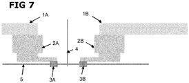
- die Komponenten in ihren Positionen während des Schneide-Vorganges.
-
Fig. 1 zeigt eine Übersicht der beteiligten mechanischen Komponenten, die Teile einer Kabelbearbeitungsmaschine sind. Jede Handhabungseinheit für das Kabel 5 ist dabei als Schwenkarmeinheit bzw. Transport- und Schwenkeinheit ausgebildet. Eine PushPull Achse 1A eines Schwenkarms einer ersten Seite der Maschine gestattet eine lineare Bewegung der daran befestigten Komponenten. An dieser Achse 1A ist im dargestellten Ausführungsbeispiel der Maschine ein Schwenkarm 2A angebracht, mittels welchen Arms 2A ein daran gehaltener Abschnitt des Kabels 5 entlang einer Kreisbahn verschwenkt werden kann. Damit kann dieser Abschnitt beispielsweise unterschiedlichen Bearbeitungsstationen zugeführt und davon wegbewegt werden. Gehalten wird das Kabel 5 dabei von einem ersten Transportgreifer 3A der ersten Seite der Maschine. - Eine zweite Seite der Maschine ist mit genau entsprechenden Komponenten ausgestattet. Ein weiterer Schwenkarm 2B der zweiten Seite der Maschine ist auf einer zweiten PushPull Achse 1B befestigt. Der zweite Schwenkarm 2B trägt wieder einen zweiten Transportgreifer 3B, mit dem ein Kabelabschnitt geklemmt werden kann.
- Im Bereich der zweiten Seite der Maschine ist weiters ein Lineareinzug 2C angeordnet, mit einem linear beweglichen Lineareinzugsgreifer 3C. Die Bewegungsrichtung des Lineareinzugsgreifers 3C liegt dabei parallel und insbesondere koaxial zur Bewegungsrichtung des ersten Transportgreifers 3A, wenn dieser das Kabel 5 nach dem Einziehen geklemmt hält und mittels der PushPull Achse 1A bewegt wird.
- Mit 4 ist schliesslich das Sägeblatt einer Kreissäge zum Ablängen des Kabels 5 bezeichnet. Diese Schneideinheit, insbesondere das Sägeblatt 4, befindet sich zwischen den beiden Transportgreifern 3A, 3B.
-
Fig. 2 stellt die Verhältnisse bei Start des Einzuges des Kabels 5 in die Kabelbearbeitungsmaschine dar. Die PushPull Achse des Schwenkarms 1A befindet sich auf Übergabe Position. Der Lineareinzug 2C hält die Kabelspitze mit dem Lineareinzugsgreifer 3C und der Greifer 2A der ersten Seite der Maschine geht auf Führungsposition, sodass das Kabel 5 in den Greiferbacken 3A lose geführt ist. - In
Fig. 3 ist der Kabeleinzug gezeigt. Der Lineareinzug 2C zieht das Kabel 5 auf die gewünschte Länge. Danach schliesst der Greifer 2A der ersten Seite. Wegen Durchhang und Kabelkrümmungen stimmt die Kabellänge jedoch nicht korrekt. Daher wird in einem nächsten Schritt das Kabel gestreckt. -
Fig. 4 zeigt die Verhältnisse während dieser Streckfunktion. Der Greifer 2A der ersten Seite ist in geschlossenem Zustand und die Greiferbacken 3A halten das Kabel. Die PushPull Achse 1A des Schwenkarms der ersten Seite der Maschine wird in den kraftgesteuerten Modus umgeschaltet. Mit einstellbarer definierter Kraft zieht die PushPull Achse 1A das Kabel zurück, das Kabel wird gestreckt. - Anschliessend erfolgt vorzugsweise und wie in
Fig. 5 dargestellt die Positionsübernahme mit dem Schwenkarm Seite 2. Dazu wird der Schwenkarm 1B der zweiten Seite der Maschine in die Kabelachse eingeschwenkt und schliesst den Greifer 2B an definierter Position. Das Kabel wird nun von allen Greiferbacken 3A, 3B und 3C gehalten. Das Einschwenken kann auch parallel zum Ablauf des inFig. 3 gezeigten Kabeleinzugs und der Streckfunktion gemässFig. 4 erfolgen. -
Fig. 6 zeigt die Freigabe des Lineareinzugs, wobei die PushPull Achse 1B des Schwenkarms der zweiten Seite der Maschine das Kabel an einer Position hält, die gegenüber beispielsweise dem Sägeblatt 4 einer Kreissäge definiert ist. Dadurch ist auch die ganze Kabellänge definiert und der Lineareinzug 2C kann bei Bedarf das Kabel loslassen und auf eine Warteposition gehen. - Die PushPull Achse 1A der ersten Seite kann bei grossen Streckfahrwegen den Greifer 2A öffnen und auf die gewünschte Kabelüberhang-Position vorfahren. Bei kleinen Rückzugswegen kann auch direkt die Position vom Rückzug für die weitere Verarbeitung verwendet werden.
- Letztlich erfolgt das Schneiden des Kabels 5, wie in
Fig. 7 dargestellt. Mit dem Sägeblatt 4 der Kreissäge wird das Kabel 5 getrennt und somit auf eine reproduzierbar genaue Länge zugeschnitten. - Weitere Varianten und Ausführungsbeispiele der Erfindung sind möglich, insbesondere für die Handhabungseinheit(en) für das Kabel. Hier können Schwenkarmeinheiten und Lineartransporteinheiten in beliebiger Anordnung und auf beliebiger Seite der Maschine kombiniert aber jedenfalls durch den Lineareinzug ergänzt werden.
-
- 1A
- PushPull Achse des Schwenkarms der ersten Seite
- 1B
- PushPull Achse des Schwenkarms der zweiten Seite
- 2A
- Schwenkarm Greifer der ersten Seite der Maschine
- 2B
- Schwenkarm Greifer der zweiten Seite der Maschine
- 2C
- Lineareinzug Greifer
- 3A
- Greiferbacke des Schwenkarms der ersten Seite
- 3B
- Greiferbacke des Schwenkarms der zweiten Seite
- 3C
- Greiferbacke vom Lineareinzug
- 4
- Kreissäge
- 5
- Kabel
Claims (5)
- Kabelbearbeitungsmaschine mit zumindest einer Handhabungseinheit (1A, 2A, 3A; 1B, 2B, 3B) für ein zu bearbeitendes Kabel (5), mit zumindest einer Bearbeitungsstation für das Kabel (5), wobei das Kabel (5) mittels der Handhabungseinheit (1A, 2A, 3A; 1B, 2B, 3B) von und zu jeder Bearbeitungsstation verbracht werden kann, wobei zumindest eine Bearbeitungsstation eine Schneideinheit (4) zum Ablängen des Kabels (5) aufweist, dadurch gekennzeichnet, dass die Kabelbearbeitungsmaschine einen Lineareinzug (2C) mit einem Lineareinzugsgreifer (3C) für das Kabel (5) aufweist und die Handhabungseinheit (1A, 2A, 3A; 1B, 2B, 3B) einen ersten Transportgreifer (3A) aufweist, wobei der erste Transportgreifer (3A) und der Lineareinzugsgreifer (3C) in eine Relativposition verfahrbar sind, in welcher das Kabel (5) mit einer vorgebbaren Kraft gespannt gehalten ist.
- Kabelbearbeitungsmaschine nach Anspruch 1, dadurch gekennzeichnet, dass die Handhabungseinheit (1A, 2A, 3A; 1B, 2B, 3B) einen zweiten Transportgreifer (3B) aufweist, welcher in eine Position zwischen dem ersten Transportgreifer (3A) und dem Lineareinzugsgreifer (3C) verfahrbar ist.
- Kabelbearbeitungseinheit nach Anspruch 1 oder 2, dadurch gekennzeichnet, dass die Schneideinheit (4) zwischen dem ersten Transportgreifer (3A) und dem Lineareinzugsgreifer (3C) positioniert ist, vorzugsweise zwischen dem ersten Transportgreifer (3A) und dem zweiten Transportgreifer (3B).
- Verfahren zum Ablängen eines Kabels, wobei das Kabel (5) an zwei Positionen geklemmt und zwischen diesen Positionen durchgeschnitten wird, dadurch gekennzeichnet, dass das Kabel (5) in einem Lineareinzugsgreifer (3C) geklemmt und in Richtung seiner Längsachse in eine Position eingezogen wird, in welcher es im Abstand vom Lineareinzugsgreifer (3C) in einem ersten Transportgreifer (3A) geklemmt wird, wobei nach dem Klemmen das Kabel (5) zwischen dem Lineareinzugsgreifer (3C) und dem ersten Transportgreifer (3A) mit einer vorgebbaren Kraft gespannt wird.
- Verfahren nach Anspruch 4, dadurch gekennzeichnet, dass das Kabel (5) zusätzlich an einer Position zwischen dem Lineareinzugsgreifer (3C) und dem ersten Transportgreifer (3A) mittels eines zweiten Transportgreifers (3B) geklemmt und anschliessend zwischen den beiden Transportgreifern (3A, 3B) durchtrennt wird.
Priority Applications (1)
| Application Number | Priority Date | Filing Date | Title |
|---|---|---|---|
| EP17170281.4A EP3402020B1 (de) | 2017-05-09 | 2017-05-09 | Kabelbearbeitungsmaschine sowie verfahren zum ablängen eines kabels |
Applications Claiming Priority (1)
| Application Number | Priority Date | Filing Date | Title |
|---|---|---|---|
| EP17170281.4A EP3402020B1 (de) | 2017-05-09 | 2017-05-09 | Kabelbearbeitungsmaschine sowie verfahren zum ablängen eines kabels |
Publications (2)
| Publication Number | Publication Date |
|---|---|
| EP3402020A1 true EP3402020A1 (de) | 2018-11-14 |
| EP3402020B1 EP3402020B1 (de) | 2021-07-07 |
Family
ID=58701451
Family Applications (1)
| Application Number | Title | Priority Date | Filing Date |
|---|---|---|---|
| EP17170281.4A Active EP3402020B1 (de) | 2017-05-09 | 2017-05-09 | Kabelbearbeitungsmaschine sowie verfahren zum ablängen eines kabels |
Country Status (1)
| Country | Link |
|---|---|
| EP (1) | EP3402020B1 (de) |
Cited By (1)
| Publication number | Priority date | Publication date | Assignee | Title |
|---|---|---|---|---|
| CN115837439A (zh) * | 2022-07-28 | 2023-03-24 | 常州数控技术研究所 | 一种斜拉线组装生产线及组装方法 |
Citations (3)
| Publication number | Priority date | Publication date | Assignee | Title |
|---|---|---|---|---|
| US826077A (en) * | 1905-09-06 | 1906-07-17 | Mayhew A Vincent | Wire-straightening and cutting machine. |
| US4663822A (en) * | 1985-11-29 | 1987-05-12 | Artos Engineering Company | Cutter/stripper/coiling apparatus for thick cable segments |
| EP2028732A2 (de) * | 2007-08-24 | 2009-02-25 | Schäfer Werkzeug- und Sondermaschinenbau GmbH | Verfahren und Vorrichtung zum Erzeugen und nachfolgenden Konfektionieren eines Kabelabschnitts an seinem Vorder- und Hinterende |
Family Cites Families (2)
| Publication number | Priority date | Publication date | Assignee | Title |
|---|---|---|---|---|
| EP1424757B1 (de) * | 2002-11-26 | 2018-03-14 | Komax Holding AG | Einrichtung zur Messung der Länge eines zu konfektionierenden Kabels |
| EP1786072B1 (de) * | 2005-11-10 | 2008-07-16 | komax Holding AG | Kabelbearbeitungseinrichtung und Verfahren für den Betrieb einer solchen Kabelbearbeitungseinrichtung |
-
2017
- 2017-05-09 EP EP17170281.4A patent/EP3402020B1/de active Active
Patent Citations (3)
| Publication number | Priority date | Publication date | Assignee | Title |
|---|---|---|---|---|
| US826077A (en) * | 1905-09-06 | 1906-07-17 | Mayhew A Vincent | Wire-straightening and cutting machine. |
| US4663822A (en) * | 1985-11-29 | 1987-05-12 | Artos Engineering Company | Cutter/stripper/coiling apparatus for thick cable segments |
| EP2028732A2 (de) * | 2007-08-24 | 2009-02-25 | Schäfer Werkzeug- und Sondermaschinenbau GmbH | Verfahren und Vorrichtung zum Erzeugen und nachfolgenden Konfektionieren eines Kabelabschnitts an seinem Vorder- und Hinterende |
Cited By (1)
| Publication number | Priority date | Publication date | Assignee | Title |
|---|---|---|---|---|
| CN115837439A (zh) * | 2022-07-28 | 2023-03-24 | 常州数控技术研究所 | 一种斜拉线组装生产线及组装方法 |
Also Published As
| Publication number | Publication date |
|---|---|
| EP3402020B1 (de) | 2021-07-07 |
Similar Documents
| Publication | Publication Date | Title |
|---|---|---|
| EP2871736A1 (de) | Anlage zur Bearbeitung eines mehradrigen Kabels | |
| EP2897744B1 (de) | Vorrichtung und verfahren zum automatischen verdrillen von metalldrähten, insbesondere zum verbinden benachbarter, vorzugweise sich überkreuzender strukturelemente | |
| EP3408904B1 (de) | Kabelbearbeitungseinrichtung | |
| EP2777053A1 (de) | Verdrillvorrichtung | |
| EP0598276B1 (de) | Kabelzuführungs- und -wechseleinrichtung für eine Kabelverarbeitungsmaschine | |
| DE3887406T2 (de) | Verfahren und Vorrichtung zum maschinellen Krimpen eines Verbindungsteiles mit den Enden meherer leitenden Drähte. | |
| DE102018131444A1 (de) | Ablängautomat und modulares Kabelverarbeitungscenter | |
| EP3544131B1 (de) | Kabelverarbeitungsmaschine mit bewegbaren führungselementen und verfahren zum einlegen eines kabels in eine kabelverarbeitungsmaschine | |
| EP2409940B1 (de) | Kabelbearbeitungsmaschine mit Längenausgleichseinheit | |
| EP3557592A1 (de) | Vorrichtung und verfahren zum verdrillen einer ersten und zweiten elektrischen einzelleitung zu einem leitungspaar | |
| EP2372848B1 (de) | Vorrichtung und Verfahren zur Bestückung von Kabeln mit Tüllen | |
| DE102019213325A1 (de) | Montagekopf sowie Verfahren zur automatisierten Umwicklung eines Leitungsstrangs | |
| EP4177908B1 (de) | Vorrichtung und verfahren zum verdrillen von einzelleitungen | |
| DE202010001324U1 (de) | Vorrichtung zum Verdrillen von Leitungen | |
| EP4402704B1 (de) | Montagekopf sowie verfahren zur automatisierten umwicklung eines leitungsstrangs | |
| DE102016109155B3 (de) | Verdrillanlage, Tandem-Verdrillanlage und Verfahren zum Bestücken eines Verdrillkopfs | |
| EP3402020B1 (de) | Kabelbearbeitungsmaschine sowie verfahren zum ablängen eines kabels | |
| EP2871732A1 (de) | Vorrichtung zur Öffnung des geflochtenen Schirms eines Kabels | |
| EP3652817B1 (de) | Drahthandlingvorrichtung | |
| EP1988044B1 (de) | Wickler und Verfahren zum Herstellen eines Wickels | |
| DE102019107073B4 (de) | Vorrichtung und verfahren zum automatisierten abbinden von kabeln | |
| EP1987897B1 (de) | Einrichtung und Verfahren zur Übernahme eines zu einem Wickel geformten Kabelabschnittes | |
| DE112023005622T5 (de) | Kabelbaum-Herstellungsgerät und Kabelbaum-Herstellungsverfahren | |
| EP4447074A1 (de) | Sequenzverdriller | |
| EP3020672B1 (de) | Vorrichtung zum Aufwickeln eines biegeschlaffen strangförmigen Elements und Verfahren dazu |
Legal Events
| Date | Code | Title | Description |
|---|---|---|---|
| PUAI | Public reference made under article 153(3) epc to a published international application that has entered the european phase |
Free format text: ORIGINAL CODE: 0009012 |
|
| STAA | Information on the status of an ep patent application or granted ep patent |
Free format text: STATUS: THE APPLICATION HAS BEEN PUBLISHED |
|
| AK | Designated contracting states |
Kind code of ref document: A1 Designated state(s): AL AT BE BG CH CY CZ DE DK EE ES FI FR GB GR HR HU IE IS IT LI LT LU LV MC MK MT NL NO PL PT RO RS SE SI SK SM TR |
|
| AX | Request for extension of the european patent |
Extension state: BA ME |
|
| STAA | Information on the status of an ep patent application or granted ep patent |
Free format text: STATUS: REQUEST FOR EXAMINATION WAS MADE |
|
| 17P | Request for examination filed |
Effective date: 20190514 |
|
| RBV | Designated contracting states (corrected) |
Designated state(s): AL AT BE BG CH CY CZ DE DK EE ES FI FR GB GR HR HU IE IS IT LI LT LU LV MC MK MT NL NO PL PT RO RS SE SI SK SM TR |
|
| STAA | Information on the status of an ep patent application or granted ep patent |
Free format text: STATUS: EXAMINATION IS IN PROGRESS |
|
| 17Q | First examination report despatched |
Effective date: 20200305 |
|
| RAP1 | Party data changed (applicant data changed or rights of an application transferred) |
Owner name: SCHLEUNIGER AG |
|
| GRAP | Despatch of communication of intention to grant a patent |
Free format text: ORIGINAL CODE: EPIDOSNIGR1 |
|
| STAA | Information on the status of an ep patent application or granted ep patent |
Free format text: STATUS: GRANT OF PATENT IS INTENDED |
|
| INTG | Intention to grant announced |
Effective date: 20210125 |
|
| GRAS | Grant fee paid |
Free format text: ORIGINAL CODE: EPIDOSNIGR3 |
|
| GRAA | (expected) grant |
Free format text: ORIGINAL CODE: 0009210 |
|
| STAA | Information on the status of an ep patent application or granted ep patent |
Free format text: STATUS: THE PATENT HAS BEEN GRANTED |
|
| AK | Designated contracting states |
Kind code of ref document: B1 Designated state(s): AL AT BE BG CH CY CZ DE DK EE ES FI FR GB GR HR HU IE IS IT LI LT LU LV MC MK MT NL NO PL PT RO RS SE SI SK SM TR |
|
| REG | Reference to a national code |
Ref country code: GB Ref legal event code: FG4D Free format text: NOT ENGLISH |
|
| REG | Reference to a national code |
Ref country code: AT Ref legal event code: REF Ref document number: 1409498 Country of ref document: AT Kind code of ref document: T Effective date: 20210715 |
|
| REG | Reference to a national code |
Ref country code: DE Ref legal event code: R096 Ref document number: 502017010822 Country of ref document: DE |
|
| REG | Reference to a national code |
Ref country code: IE Ref legal event code: FG4D Free format text: LANGUAGE OF EP DOCUMENT: GERMAN |
|
| REG | Reference to a national code |
Ref country code: LT Ref legal event code: MG9D |
|
| REG | Reference to a national code |
Ref country code: NL Ref legal event code: MP Effective date: 20210707 |
|
| PG25 | Lapsed in a contracting state [announced via postgrant information from national office to epo] |
Ref country code: NL Free format text: LAPSE BECAUSE OF FAILURE TO SUBMIT A TRANSLATION OF THE DESCRIPTION OR TO PAY THE FEE WITHIN THE PRESCRIBED TIME-LIMIT Effective date: 20210707 Ref country code: NO Free format text: LAPSE BECAUSE OF FAILURE TO SUBMIT A TRANSLATION OF THE DESCRIPTION OR TO PAY THE FEE WITHIN THE PRESCRIBED TIME-LIMIT Effective date: 20211007 Ref country code: PT Free format text: LAPSE BECAUSE OF FAILURE TO SUBMIT A TRANSLATION OF THE DESCRIPTION OR TO PAY THE FEE WITHIN THE PRESCRIBED TIME-LIMIT Effective date: 20211108 Ref country code: HR Free format text: LAPSE BECAUSE OF FAILURE TO SUBMIT A TRANSLATION OF THE DESCRIPTION OR TO PAY THE FEE WITHIN THE PRESCRIBED TIME-LIMIT Effective date: 20210707 Ref country code: ES Free format text: LAPSE BECAUSE OF FAILURE TO SUBMIT A TRANSLATION OF THE DESCRIPTION OR TO PAY THE FEE WITHIN THE PRESCRIBED TIME-LIMIT Effective date: 20210707 Ref country code: FI Free format text: LAPSE BECAUSE OF FAILURE TO SUBMIT A TRANSLATION OF THE DESCRIPTION OR TO PAY THE FEE WITHIN THE PRESCRIBED TIME-LIMIT Effective date: 20210707 Ref country code: LT Free format text: LAPSE BECAUSE OF FAILURE TO SUBMIT A TRANSLATION OF THE DESCRIPTION OR TO PAY THE FEE WITHIN THE PRESCRIBED TIME-LIMIT Effective date: 20210707 Ref country code: BG Free format text: LAPSE BECAUSE OF FAILURE TO SUBMIT A TRANSLATION OF THE DESCRIPTION OR TO PAY THE FEE WITHIN THE PRESCRIBED TIME-LIMIT Effective date: 20211007 Ref country code: RS Free format text: LAPSE BECAUSE OF FAILURE TO SUBMIT A TRANSLATION OF THE DESCRIPTION OR TO PAY THE FEE WITHIN THE PRESCRIBED TIME-LIMIT Effective date: 20210707 Ref country code: SE Free format text: LAPSE BECAUSE OF FAILURE TO SUBMIT A TRANSLATION OF THE DESCRIPTION OR TO PAY THE FEE WITHIN THE PRESCRIBED TIME-LIMIT Effective date: 20210707 |
|
| PG25 | Lapsed in a contracting state [announced via postgrant information from national office to epo] |
Ref country code: PL Free format text: LAPSE BECAUSE OF FAILURE TO SUBMIT A TRANSLATION OF THE DESCRIPTION OR TO PAY THE FEE WITHIN THE PRESCRIBED TIME-LIMIT Effective date: 20210707 Ref country code: LV Free format text: LAPSE BECAUSE OF FAILURE TO SUBMIT A TRANSLATION OF THE DESCRIPTION OR TO PAY THE FEE WITHIN THE PRESCRIBED TIME-LIMIT Effective date: 20210707 Ref country code: GR Free format text: LAPSE BECAUSE OF FAILURE TO SUBMIT A TRANSLATION OF THE DESCRIPTION OR TO PAY THE FEE WITHIN THE PRESCRIBED TIME-LIMIT Effective date: 20211008 |
|
| REG | Reference to a national code |
Ref country code: DE Ref legal event code: R097 Ref document number: 502017010822 Country of ref document: DE |
|
| PG25 | Lapsed in a contracting state [announced via postgrant information from national office to epo] |
Ref country code: DK Free format text: LAPSE BECAUSE OF FAILURE TO SUBMIT A TRANSLATION OF THE DESCRIPTION OR TO PAY THE FEE WITHIN THE PRESCRIBED TIME-LIMIT Effective date: 20210707 |
|
| PLBE | No opposition filed within time limit |
Free format text: ORIGINAL CODE: 0009261 |
|
| STAA | Information on the status of an ep patent application or granted ep patent |
Free format text: STATUS: NO OPPOSITION FILED WITHIN TIME LIMIT |
|
| PG25 | Lapsed in a contracting state [announced via postgrant information from national office to epo] |
Ref country code: SM Free format text: LAPSE BECAUSE OF FAILURE TO SUBMIT A TRANSLATION OF THE DESCRIPTION OR TO PAY THE FEE WITHIN THE PRESCRIBED TIME-LIMIT Effective date: 20210707 Ref country code: SK Free format text: LAPSE BECAUSE OF FAILURE TO SUBMIT A TRANSLATION OF THE DESCRIPTION OR TO PAY THE FEE WITHIN THE PRESCRIBED TIME-LIMIT Effective date: 20210707 Ref country code: RO Free format text: LAPSE BECAUSE OF FAILURE TO SUBMIT A TRANSLATION OF THE DESCRIPTION OR TO PAY THE FEE WITHIN THE PRESCRIBED TIME-LIMIT Effective date: 20210707 Ref country code: EE Free format text: LAPSE BECAUSE OF FAILURE TO SUBMIT A TRANSLATION OF THE DESCRIPTION OR TO PAY THE FEE WITHIN THE PRESCRIBED TIME-LIMIT Effective date: 20210707 Ref country code: CZ Free format text: LAPSE BECAUSE OF FAILURE TO SUBMIT A TRANSLATION OF THE DESCRIPTION OR TO PAY THE FEE WITHIN THE PRESCRIBED TIME-LIMIT Effective date: 20210707 Ref country code: AL Free format text: LAPSE BECAUSE OF FAILURE TO SUBMIT A TRANSLATION OF THE DESCRIPTION OR TO PAY THE FEE WITHIN THE PRESCRIBED TIME-LIMIT Effective date: 20210707 |
|
| 26N | No opposition filed |
Effective date: 20220408 |
|
| PG25 | Lapsed in a contracting state [announced via postgrant information from national office to epo] |
Ref country code: IT Free format text: LAPSE BECAUSE OF FAILURE TO SUBMIT A TRANSLATION OF THE DESCRIPTION OR TO PAY THE FEE WITHIN THE PRESCRIBED TIME-LIMIT Effective date: 20210707 |
|
| REG | Reference to a national code |
Ref country code: BE Ref legal event code: MM Effective date: 20220531 |
|
| GBPC | Gb: european patent ceased through non-payment of renewal fee |
Effective date: 20220509 |
|
| PG25 | Lapsed in a contracting state [announced via postgrant information from national office to epo] |
Ref country code: MC Free format text: LAPSE BECAUSE OF FAILURE TO SUBMIT A TRANSLATION OF THE DESCRIPTION OR TO PAY THE FEE WITHIN THE PRESCRIBED TIME-LIMIT Effective date: 20210707 Ref country code: LU Free format text: LAPSE BECAUSE OF NON-PAYMENT OF DUE FEES Effective date: 20220509 |
|
| PG25 | Lapsed in a contracting state [announced via postgrant information from national office to epo] |
Ref country code: IE Free format text: LAPSE BECAUSE OF NON-PAYMENT OF DUE FEES Effective date: 20220509 Ref country code: FR Free format text: LAPSE BECAUSE OF NON-PAYMENT OF DUE FEES Effective date: 20220531 |
|
| PG25 | Lapsed in a contracting state [announced via postgrant information from national office to epo] |
Ref country code: GB Free format text: LAPSE BECAUSE OF NON-PAYMENT OF DUE FEES Effective date: 20220509 Ref country code: BE Free format text: LAPSE BECAUSE OF NON-PAYMENT OF DUE FEES Effective date: 20220531 |
|
| P01 | Opt-out of the competence of the unified patent court (upc) registered |
Effective date: 20230606 |
|
| REG | Reference to a national code |
Ref country code: AT Ref legal event code: MM01 Ref document number: 1409498 Country of ref document: AT Kind code of ref document: T Effective date: 20220509 |
|
| PG25 | Lapsed in a contracting state [announced via postgrant information from national office to epo] |
Ref country code: AT Free format text: LAPSE BECAUSE OF NON-PAYMENT OF DUE FEES Effective date: 20220509 |
|
| PG25 | Lapsed in a contracting state [announced via postgrant information from national office to epo] |
Ref country code: HU Free format text: LAPSE BECAUSE OF FAILURE TO SUBMIT A TRANSLATION OF THE DESCRIPTION OR TO PAY THE FEE WITHIN THE PRESCRIBED TIME-LIMIT; INVALID AB INITIO Effective date: 20170509 |
|
| REG | Reference to a national code |
Ref country code: DE Ref legal event code: R082 Ref document number: 502017010822 Country of ref document: DE Representative=s name: ROSENICH, PAUL, DIPL.-HTL-ING., LI |
|
| PG25 | Lapsed in a contracting state [announced via postgrant information from national office to epo] |
Ref country code: MK Free format text: LAPSE BECAUSE OF FAILURE TO SUBMIT A TRANSLATION OF THE DESCRIPTION OR TO PAY THE FEE WITHIN THE PRESCRIBED TIME-LIMIT Effective date: 20210707 Ref country code: CY Free format text: LAPSE BECAUSE OF FAILURE TO SUBMIT A TRANSLATION OF THE DESCRIPTION OR TO PAY THE FEE WITHIN THE PRESCRIBED TIME-LIMIT Effective date: 20210707 |
|
| PG25 | Lapsed in a contracting state [announced via postgrant information from national office to epo] |
Ref country code: TR Free format text: LAPSE BECAUSE OF FAILURE TO SUBMIT A TRANSLATION OF THE DESCRIPTION OR TO PAY THE FEE WITHIN THE PRESCRIBED TIME-LIMIT Effective date: 20210707 |
|
| PG25 | Lapsed in a contracting state [announced via postgrant information from national office to epo] |
Ref country code: MT Free format text: LAPSE BECAUSE OF FAILURE TO SUBMIT A TRANSLATION OF THE DESCRIPTION OR TO PAY THE FEE WITHIN THE PRESCRIBED TIME-LIMIT Effective date: 20210707 |
|
| PGFP | Annual fee paid to national office [announced via postgrant information from national office to epo] |
Ref country code: DE Payment date: 20250521 Year of fee payment: 9 |
|
| PGFP | Annual fee paid to national office [announced via postgrant information from national office to epo] |
Ref country code: CH Payment date: 20250601 Year of fee payment: 9 |
|
| REG | Reference to a national code |
Ref country code: CH Ref legal event code: R17 Free format text: ST27 STATUS EVENT CODE: U-0-0-R10-R17 (AS PROVIDED BY THE NATIONAL OFFICE) Effective date: 20260417 |